Article

Structural Topology Optimisation of a Composite Wind Turbine Blade Under Various Constraints

by
Mohamed Noufel Ajmal Khan
1 and
Mertol Tüfekci
1,2,*
1
School of Physics, Engineering and Computer Science, College Lane Campus, University of Hertfordshire, Hatfield AL10 9AB, UK
2
Centre for Engineering Research, College Lane Campus, University of Hertfordshire, Hatfield AL10 9AB, UK
*
Author to whom correspondence should be addressed.
Submission received: 2 February 2025 / Revised: 22 September 2025 / Accepted: 23 September 2025 / Published: 28 September 2025

Abstract

This study investigates the topology optimisation of a composite wind turbine blade with the objective of improving its structural performance under static and dynamic constraints. Two distinct optimisation strategies—based on static deformation limits and modal frequency enhancement—are employed to achieve mass reduction while maintaining or improving mechanical performance. The optimisation process incorporates modal characterisation of the first ten natural frequencies and a detailed static stress analysis. Results indicate that the optimised designs achieve a notable increase in the fundamental natural frequency of the blade—from 2.32 Hz to 2.99 Hz—and reduce the overall mass by approximately 49%, lowering it from 4.55 × 10⁵ kg to around 2.34 × 10⁵ kg compared to the original configuration. In particular, the optimised geometry offers improved stiffness and a more uniform stress distribution, especially in the flapwise bending and torsional modes. Higher-order torsional frequencies remain well-separated from typical excitation sources, minimising resonance risks. These findings highlight the effectiveness of constraint-driven topology optimisation in enhancing structural performance and reducing material usage in wind turbine blade design.

1. Introduction

Wind turbine blades are essential components in harnessing wind energy, transforming it into mechanical power. As the wind power industry develops, there is a growing demand for larger and more efficient blades. Designing and optimising these blades pose significant engineering challenges. Critical aspects of wind turbine blade design include the selection of materials, aerodynamic and structural considerations, and optimisation techniques. Various blade types and materials are employed, such as fibreglass-reinforced composites, carbon fibre, and aluminium, with designs ranging from flat to curved or gull-wing tips. Blades are subjected to lift, drag, centrifugal, and gravitational forces. The size of the blades is a critical factor influencing the power output of wind turbines, which can range from small units generating 10 kW to large turbines producing up to 15 MW.
The structural design of wind turbine blades aims to enhance structural performance, reduce weight, and lower costs through innovative configurations and optimisation techniques. Topology optimisation applied to a 45 m blade resulted in a non-prismatic shape that reduces stress and increases stiffness, demonstrating the effectiveness of offset spar cap topology and trailing edge reinforcement in material reduction and cost savings [1]. The coupled multi-objective shape and topology optimisation framework for Horizontal-Axis Wind Turbine blades simultaneously optimise internal structural arrangement and external blade shape, achieving a 16–41% reduction in structural compliance and a 4% increase in rotor power coefficient, thus enhancing power output and structural performance [2,3].
Finite element analysis has been extensively used to assess fatigue life cycles and the performance of composite materials in wind turbine blades. Studies utilising finite element software evaluated materials like glass fibre-reinforced plastic (GFRP), carbon fibre-reinforced plastic (CFRP), titanium and aluminium alloys. Findings indicate that while CFRP exhibits maximum stress and the least deformation, GFRP and aluminium offer similar stress levels and may be more cost-effective for small wind turbine blades (blade lengths under 30 m), pending further fatigue testing [4,5]. Comparisons of composite materials such as carbon and graphite epoxy suggest that carbon epoxy composites are optimal due to their low mass and favourable stress distribution, enhancing blade performance [6,7].
Strategies incorporating flow control devices and biomimicry have been explored to improve aerodynamic, structural, and aero-acoustic properties, emphasising the importance of factors like Reynolds and Strouhal numbers and the role of turbulence models and optimisation algorithms in sustainable wind turbine design [8]. Studies have also examined the aerodynamic optimisation of icing-related power losses in small turbine blades, illustrating how environmental factors can be integrated into the optimisation process [9]. Research on the effects of 3D blade geometry on performance provides insights into trade-offs in blade design, with principles that could benefit larger blades [10]. Finite element analysis on composite laminated plates highlighted the advantages of composites due to their high strength-to-weight ratio and vibration resistance, crucial for blade design and reliability [11,12,13]. Modal analyses under various wind speed scenarios suggest design changes to reduce stress concentrations and enhance structural integrity in wind turbine towers [12,14,15].
Structural analyses under severe wind loading conditions using ANSYS and NuMAD revealed that most blade components can sustain high loads, with recommendations to optimise aerofoil, ply layup, and blade geometry for improved performance and integrity [16]. Utilising higher-order triangular meshing has been shown to improve the aerodynamic efficiency of wind turbine blades, enhancing the precision of performance forecasts and aiding in effective shape optimisation [17]. Studies on flow-induced vibrations in vertical-axis wind turbine blades emphasise the need to consider natural frequencies and vibratory stresses in blade design, with carbon epoxy composites showing promising performance [18,19,20]. Finite element analyses aimed at optimising material consumption in fibreglass composite blades evaluated natural frequencies, twisting deflections, and static bending to design strong, lightweight, and cost-effective blades, suggesting future research on dynamics and structural mechanics [21]. Analytical beam models provide simpler methods for dynamic analysis and aid in understanding scaling effects and material selection [11,22,23,24,25,26,27,28].
Topology optimisation methods have effectively reduced blade mass and enhanced stiffness, with evolutionary algorithms addressing practical challenges in manufacturing constraints and model validation [29,30]. Advanced manufacturing processes, such as 3D printing and additive manufacturing, have been employed to create high-performance, lightweight blades, demonstrating significant mass reductions and potential applications in blade optimisation [31,32,33,34,35]. Reviews of aviation engine resin matrix composite fan blades emphasise integrating mechanical design, cost-effective manufacturing, and precise damage detection for broader adoption in aerospace applications, which could inform wind turbine blade development [36].
Computational simulations and fluid–structure interaction analyses have evaluated blade performance under various conditions, highlighting the importance of considering structural flexibility, aerodynamic stresses, and aeroelastic responses in design and analysis [37,38,39,40]. These studies emphasise that integrating advanced materials, topology optimisation, and aerodynamic considerations can significantly improve blade performance, structural integrity, and efficiency, contributing to the development of more effective and sustainable wind energy systems.
Recent studies have explored advanced optimisation strategies to enhance wind turbine performance. In [41], a Darrieus-type vertical axis wind turbine (VAWT) was improved using auxiliary blades and deflectors, resulting in a 73% increase in efficiency at high tip-speed ratios. Building on this, ref. [42] proposed a dual-shaft hybrid Darrieus–Savonius VAWT, mitigating high-TSR inefficiencies and achieving a 35% efficiency gain in the low-TSR regime. Ref. [43] conducted a 3D-CFD analysis to evaluate the effects of rotor parameters such as overlap ratio, spacing, and arc angle on the aerodynamic performance of Savonius turbines. Their optimised configuration significantly boosted the power coefficient. Meanwhile, ref. [44] applied optimisation methods including Kriging and RSM to a small-scale horizontal axis wind turbine (HAWT) and achieved up to an 11% improvement in power coefficient using the QBlade platform.
The aim of this study is to perform and evaluate topology optimisation for wind turbine blade design, with a focus on improving structural integrity and dynamic performance. Existing studies on blade optimisation often prioritise aerodynamic shape design, while fewer address structural material distribution within fixed geometries, particularly using constraint-driven topology optimisation. To bridge this gap, the present work targets a horizontal-axis wind turbine blade and integrates finite element analysis with structural topology optimisation, while preserving the original aerodynamic outer surface. Unlike previous works that focus solely on mass minimisation or natural frequency enhancement, this study incorporates both static and modal constraints to evaluate their influence on structural response. A comprehensive characterisation of the first ten natural frequencies and a static stress assessment are conducted to assess the impact of the optimisation strategies. By maintaining aerodynamic integrity and focusing on internal material redistribution, this study offers a practical approach to improving stiffness, stress distribution, and vibrational performance. The findings contribute to the growing body of research on the structural optimisation of renewable energy systems and highlight how constraint-based internal reconfiguration can improve structural efficiency in composite wind turbine blades. The novelty of this work lies in the dual-path optimisation strategy, allowing for a comparative evaluation of static- and dynamic-driven design objectives within a unified framework. This approach provides deeper insight into the trade-offs and synergies between mass reduction, vibrational safety, and stress control, which are often treated in isolation in the existing literature.

2. Description of the Wind Turbine Blade

2.1. Geometry of the Blade

The selected wind turbine blade geometry has a total length of 30.27 m. At the root, the blade has a circular cross-section with a diameter of 2.47 m, transitioning through a round disc attachment. This root section extends over 2.06 m before tapering into the midsection. The midsection spans 9.9 m and features a streamlined transition towards the blade’s tip. The remaining 18.31 m represent the tapered tip, where the blade narrows to improve aerodynamic performance. This design optimises the blade’s structural and aerodynamic properties, improving energy efficiency. The blade has a composite skin that covers the core. These components are rigidly tied to each other to maintain the assembly in the model. The blade geometry model is shown in Figure 1 and some geometric features are shown in Table 1.

2.2. Mechanical Properties of the Materials

Building on the features of carbon fibre discussed in the initial static structural analysis, the mechanical properties of the composite material are explored in further detail. CFRP is an ideal material for wind turbine blade applications due to its significant rigidity and strength-to-weight ratio. Due to its anisotropic nature, the mechanical properties of CFRP can be optimised in specific directions to enhance blade performance. In line with values reported in the literature for carbon fibre–epoxy laminates [45], a fibre volume fraction of approximately 60% was considered. Each ply thickness was taken as 0.327 mm, and the composite skin was modelled as a laminate comprising approximately 100 plies, giving a total shell thickness of 32.7 mm. A representative stacking sequence of (0/45/90/−45/0) was repeated throughout the layup, following classical laminate notation. The fibre volume fraction, number of plies, and orientation critically impact the composite’s overall performance, particularly affecting fatigue resistance, tensile strength, and flexural modulus. For the analysis, the composite skin is homogenised into an isotropic material with the following properties: density of 2000 kg/m3, Young’s modulus of 110 GPa, and Poisson’s ratio of 0.3 [11]. The ply properties are summarised in Table 2

2.3. Exploring the Mechanical Characteristics of the Blade

An initial structural analysis is conducted using ANSYS Workbench to evaluate the mechanical characteristics of the selected blade geometry. The blade model is imported into the software for finite element analysis. To construct a set of self-consistent modelling conditions, a fixed support is applied at the root end of the blade, representing its attachment to the hub. Load cases are implemented to assess the blade under different conditions, including pressure distributions representing aerodynamic loads with magnitudes of 10,000 Pa, 20,000 Pa, and 30,000 Pa [46,47]. Even though it would be expected that the pressure acting on the blade should not be constant, for this particular study, it is seen that this simplification of loads is representative of the operational conditions.
The aerodynamic pressure values of 10,000 Pa, 20,000 Pa, and 30,000 Pa were selected to represent a range of realistic loading conditions experienced by large-scale wind turbine blades during different wind events. These values correspond to typical operational and extreme gust scenarios, covering a broad spectrum of structural responses. Although fluid–structure interaction (FSI) is not addressed directly in this study, the chosen pressure levels provide a representative spectrum of aerodynamic loads suitable for evaluating and comparing the effectiveness of different optimisation strategies.
The structural analysis determines the blade’s response to the applied loads by evaluating key parameters such as structural deformation, directional deformation, von Mises stress, and maximum elastic strain. Structural deformation assesses the overall deflection to ensure it remains within acceptable limits, while directional deformation provides insights into the blade’s behaviour along specific axes under load. The von Mises stress analysis identified areas of high-stress concentration that could indicate potential failure points under predefined loads.

3. Topology Optimisation of the Wind Turbine Blades

The primary objective of this study is to optimise the topology of a wind turbine blade by reducing the size of its aluminium core without compromising structural integrity or dynamic performance. Both static and modal analyses are employed using ANSYS Workbench to achieve this goal. The optimisation aims to minimise compliance under static loading conditions and increase the first natural frequency in modal analysis.

3.1. Initial Design and Constraints

3.1.1. Blade Geometry, Mesh Structure and the Numerical Model

The wind turbine blade model used in this study is shown in Figure 2. A finite element mesh was generated with a maximum element size of 0.2 m, yielding a total of 101,627 nodes and 64,410 elements. A hybrid meshing strategy was adopted: quadrilateral elements were applied in the hub region to better accommodate the geometry’s regular topology and structural attachment interfaces, while triangular elements were employed along the blade’s length, particularly towards the tip, to allow for flexibility in capturing complex curvatures and varying cross-sectional transitions. This meshing approach ensured an adequate balance between geometric fidelity and computational cost. Furthermore, a mesh convergence study was conducted to confirm that the selected mesh density results in stable and reliable outputs for both static and modal analyses.
It is also essential to note that the mesh independence study is conducted and the selected mesh—consisting of 64,410 elements and 101,627 nodes with a maximum element size of 0.2 m—was confirmed to produce consistent and stable results for both static and modal analyses, indicating that further mesh refinement would not significantly alter the outcome.

3.1.2. Boundary Conditions and Load Cases

To simulate realistic operational conditions, a rotational velocity of 22.3 RPM (equivalent to an angular velocity of 2.33 rad/s and wind speed of approximately 10 m/s, for a 30 m blade radius and a tip-speed ratio of 7) is selected based on typical operating speeds and tip speed ratios for a 30-metre blade. This rotational speed corresponds to a blade tip speed of approximately 70 m/s, which falls within the standard range for this size of wind turbine. The influence of rotational motion is reflected in the centrifugal stiffening of the blade structure, particularly along the span, contributing to improved bending stiffness in the axial direction.
A fixed boundary condition is applied to the disc face at the root of the blade to represent its attachment to the hub, thereby constraining all degrees of freedom. Pressure loads are applied to the pressure side of the blade surface to simulate aerodynamic forces. Initial analyses are conducted with pressure magnitudes of 10,000 Pa, 20,000 Pa, and 30,000 Pa to understand the structural response under various operating scenarios. For the optimisation phase, the pressure load is increased to 50,000 Pa to account for more severe loading conditions. This higher pressure magnitude introduces a conservative safety margin into the design process, representing extreme but plausible wind conditions.

3.2. Optimisation Process with Static and Modal Constraints

The topology optimisation of the wind turbine blade is carried out using the structural optimisation module within ANSYS. The optimisation process is conducted separately for static and modal analyses rather than as a single integrated procedure to permit comparison of the resultant geometry under each constraint type. Consequently, the results and analyses for each case—static and modal—are presented individually.

3.2.1. Objective Function and Constraint Formulation

The optimisation process focuses on minimising the mass of the wind turbine blade while satisfying specific performance constraints in both static and modal analyses.
In the static analysis, the primary objective is to reduce the mass of the blade while imposing a constraint on the maximum allowable displacement. This approach ensures that, despite the reduction in mass, the blade maintains sufficient stiffness to limit deflections under the applied loads. Controlling displacement is critical to prevent excessive deformation that could impair the blade’s functionality or lead to structural failure during operation.
In the modal analysis, the objective remains mass minimisation, but the constraint shifts to the fundamental natural frequency of the blade. The optimisation seeks to ensure that the first natural frequency does not fall below a predetermined threshold, targeting at least a 20% increase from the initial frequency [46]. Maintaining or increasing the natural frequency is essential to avoid resonance with operational excitations, thereby preserving the dynamic performance of the blade.
This optimisation approach does not involve a multi-objective analysis; instead, it employs a single objective—mass minimisation—with different constraints applied in two separate analyses. By addressing these constraints separately in the static and modal analyses, the optimisation process allows for targeted improvements in each performance aspect. This sequential method ensures that the blade’s structural and dynamic requirements are met while achieving the overall goal of reducing mass, leading to a more efficient and effective blade design.

3.2.2. Convergence Criteria

Convergence in the optimisation process is monitored by evaluating the objective and constraint response functions for both static and modal analyses. The optimisation iterations continue until the objectives are met within predefined tolerances, ensuring that the blade design satisfies all specified performance requirements.
In the static analysis, convergence is achieved when further iterations result in negligible reductions in mass, indicating that an optimal material distribution has been reached within the displacement constraint. The change in mass between successive iterations falls below a specified threshold, and the maximum allowable displacement is not exceeded. This ensures that the blade maintains sufficient stiffness to limit deflections under the applied loading conditions while achieving mass reduction.
In the modal analysis, convergence is attained when the first natural frequency has increased by the targeted 20%, and additional iterations do not yield significant frequency enhancements [46]. Shifting the first natural frequency reduces the risk of resonance at targeted operational conditions. The optimisation continues until the mass cannot be further reduced without violating the natural frequency constraint. Maintaining or increasing the natural frequency is essential to avoid resonance with operational excitations, thereby preserving the dynamic performance of the blade.

4. Results and Discussion

4.1. Mesh Convergence Study

Mesh convergence analysis was conducted to verify the independence of the results from the discretisation density. Table 3 demonstrates the coupled convergence behaviour of maximum displacement and the fundamental natural frequency under mesh refinement. With a coarse mesh, the frequency is artificially overestimated due to excessive stiffness representation, while the corresponding displacement is underestimated. As the mesh is refined, the displacement gradually increases and the natural frequency decreases, with both quantities stabilising at mesh level 3–4. This behaviour is consistent with the variational nature of the finite element method, where eigenfrequencies obtained from coarse discretisations act as upper bounds that reduce towards the true solution, while displacements converge smoothly from below. The final mesh of 64,410 elements and 101,627 nodes was therefore selected as a mesh-independent model, balancing accuracy and computational cost.

4.2. Analysis of the Initial Geometry

To establish a baseline for the subsequent optimisation process, the initial geometry of the wind turbine blade was subjected to a series of static analyses under varying aerodynamic pressure loads. Table 4 summarises the key structural responses—total deformation, von Mises stress, maximum principal elastic strain, flapwise direction deformation, and the fundamental natural frequency—recorded for pressure magnitudes of 10,000 Pa, 20,000 Pa, and 30,000 Pa.
Although, in practice, the aerodynamic pressure acting on a wind turbine blade varies along its span, this study, similar to the approach adopted in [46], demonstrates that assuming a constant pressure load provides a sufficiently representative simplification of the operational loading conditions for the purposes of structural optimisation.
The results indicate that the structural response of the blade scales linearly with the applied aerodynamic pressure. Under a load of 10,000 Pa, the maximum total deformation was found to be approximately 5.90 × 10⁻⁷ m. When the pressure was doubled to 20,000 Pa, the deformation increased to 1.18 × 10⁻⁶ m, and a further increase in pressure to 30,000 Pa resulted in a maximum deformation of 1.77 × 10⁻⁶ m. This near-linear trend confirms that the initial design is operating within the elastic regime, where the material response is predictable and reversible.
Similarly, the maximum von Mises stress follows a proportional increase with the applied load—from 12.242 MPa to 24.483 MPa and finally 36.725 MPa. Such a uniform scaling in stress suggests that the load is being distributed evenly throughout the blade structure, thereby reducing the likelihood of localised stress concentrations that might otherwise lead to premature failure.
The maximum principal elastic strain, albeit reported in small magnitudes, also demonstrates a linear relationship with the increasing pressure. Recorded values of approximately 3.94 × 10⁻⁸, 7.89 × 10⁻⁸, and 1.18 × 10⁻⁷ for the three test cases confirm that the composite material remains well within its elastic limits, which is crucial for maintaining the blade’s structural integrity under operational conditions.
In addition to the overall deformation, the flapwise direction deformation—which is particularly critical for aerodynamic performance—was evaluated. The observed values (4.06 × 10⁻⁷ m, 8.13 × 10⁻⁷ m, and 1.22 × 10⁻⁶ m) reinforce the trend noted in the total deformation data. The proportional increase in flapwise deflection further substantiates the linear elastic behaviour of the blade, ensuring that the aerodynamic load does not induce excessive bending that could compromise performance.
Finally, the fundamental natural frequency exhibited only marginal changes across the three load cases, with values ranging from 2.3217 Hz at the lowest pressure to 2.3508 Hz at the highest. This minor variation suggests that the dynamic properties of the blade are largely independent of the static load conditions, thereby confirming the design’s stability in terms of resonance and dynamic performance.

4.3. Topology Optimisation Studies

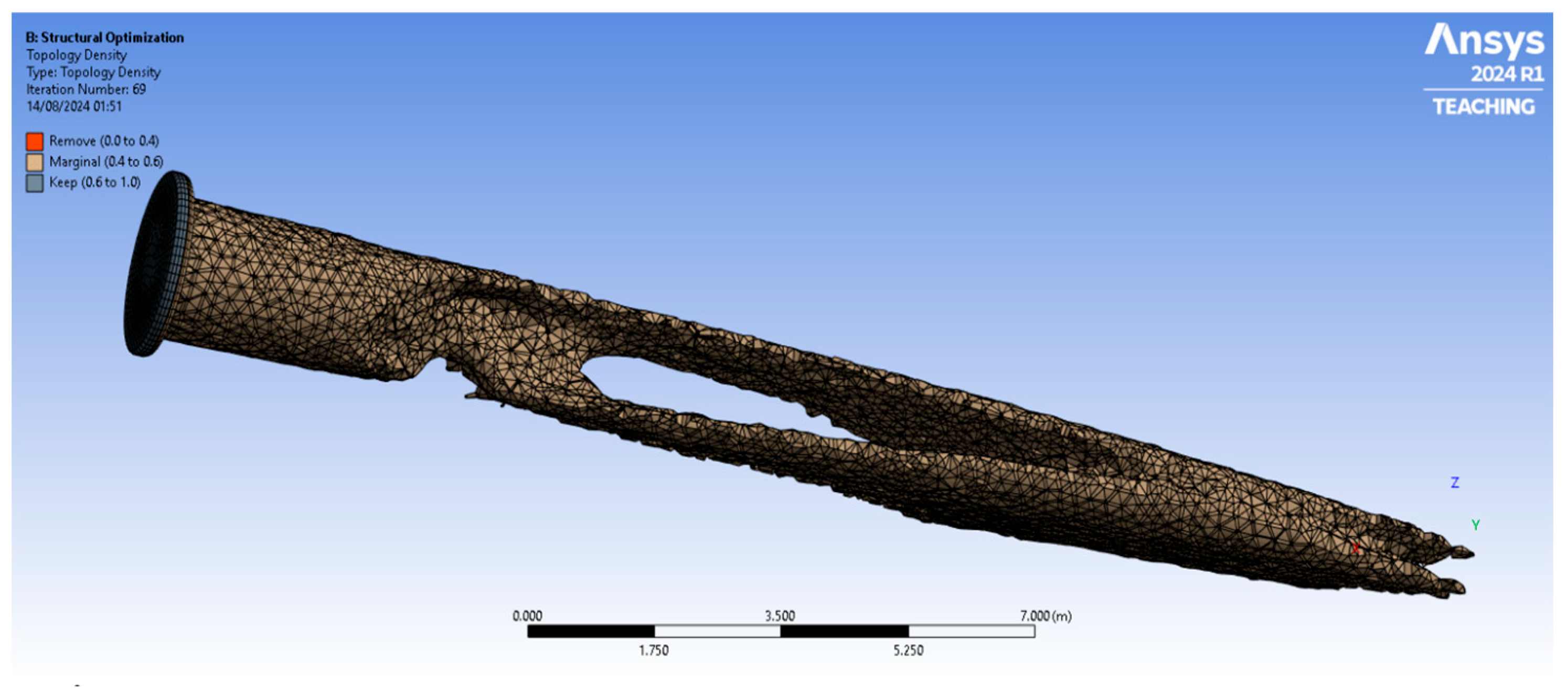
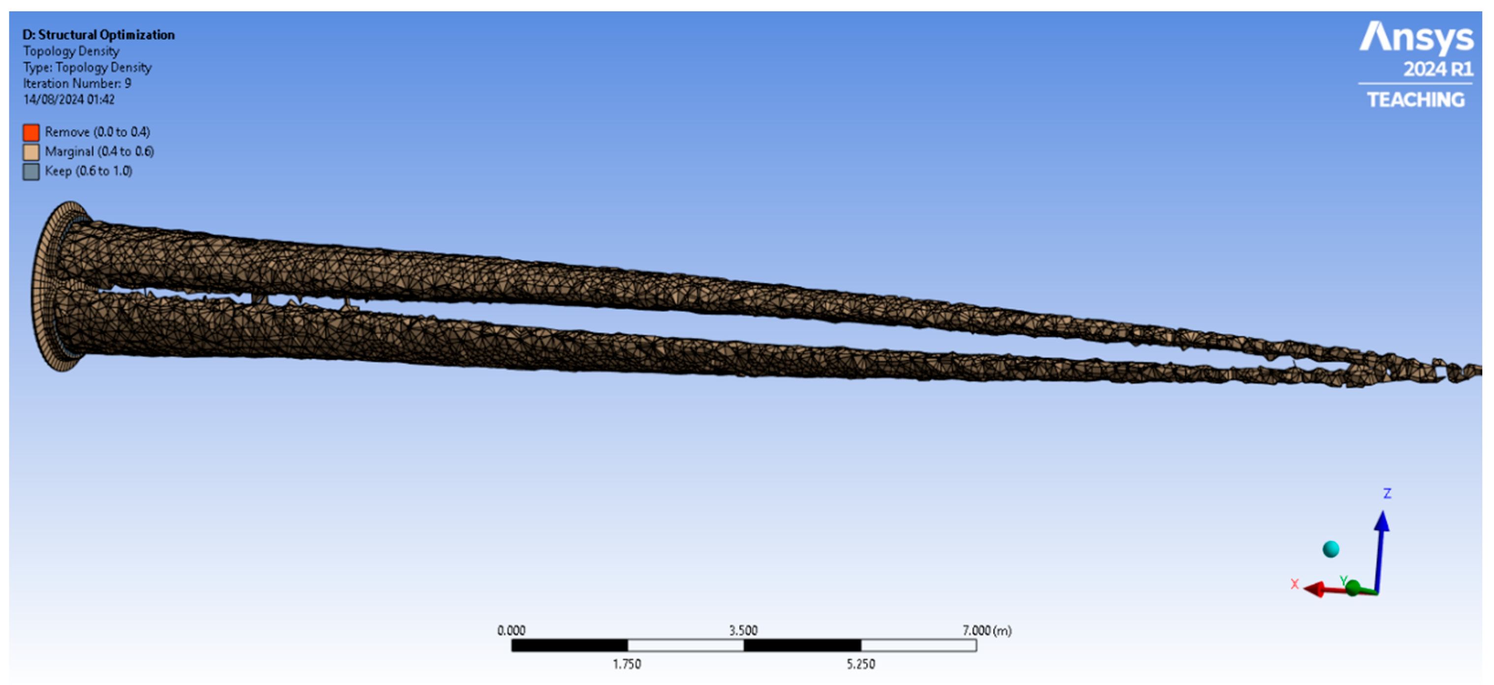
Following the baseline assessment of the initial geometry, topology optimisation was conducted under two primary constraints: (1) a static analysis targeting minimum mass subject to a maximum displacement constraint, and (2) a modal analysis aiming to raise the blade’s fundamental natural frequency above a specified threshold. Figure 3 and Figure 4 illustrate the resulting optimised structures from these two independent approaches.
In Figure 3, corresponding to the static-optimised blade, large sections of material have been removed along the mid-span. This outcome indicates that, under predominantly bending loads, certain interior regions experience relatively low stress and can therefore be sacrificed while maintaining sufficient stiffness at the root and along the load paths near the surface. The highest bending moments typically occur near the root of the blade, where the cross-sectional area remains more substantial to support flapwise forces. Consequently, the optimisation retained material around the root and outer shell—areas most critical for carrying bending loads and for resisting local stress concentrations.
By contrast, Figure 4 shows the outcome of the modal-driven optimisation. While there are still notable cavities in the internal structure, the distribution of material removal differs from the static case in order to preserve and even enhance the blade’s torsional rigidity. In a rotating wind turbine blade, aerodynamic forces impose not only bending in the flapwise direction but also twisting (torsion), especially closer to the tip. Ensuring an adequate torsional stiffness is essential to raise the fundamental natural frequency and avoid potential resonance with operational excitations. Hence, the modal optimisation retains specific bands of material along both edges and near the shell, as these regions contribute most to the blade’s overall torsional stiffness and vibrational characteristics.
Bending dominates the flapwise deformation, with the highest bending moments near the root. As a result, topology optimisation preserves material where normal stresses are large, preventing excessive deflection that could degrade aerodynamic efficiency or lead to structural failure. Torsion, conversely, is particularly critical to dynamic performance: insufficient torsional stiffness can lower the fundamental frequency into the range of rotor-speed harmonics or gust-induced excitations, risking resonance. The optimised blade shapes in Figure 3 and Figure 4 illustrate how the solver strategically retains material along load-bearing paths—particularly those that stiffen the blade against both bending and twisting. Also, Table 5 presents the numerical results.
Both optimisations demonstrate significant reductions in the interior material without compromising integrity. The root remains robust in both cases due to high bending and torsional demands at this attachment interface.
In the static-optimised design, the primary focus is on limiting total (and flapwise) deformation. Material is pared back wherever stresses are relatively low, effectively minimising compliance. In the modal-driven design, there is an added impetus to maintain or increase the blade’s first natural frequency, leading to a slightly different internal material distribution that bolsters torsional rigidity.
The resulting topologies confirm that the blade’s outer and root regions carry the brunt of structural loads. Removing less critical internal sections does not adversely affect the stiffness as long as high-stress paths remain intact.
From the static perspective, the optimised blade retains approximately half of its original volume, reducing from 58 m3 to about 29.76 m3. Correspondingly, the mass drops from 4.55 × 10⁵ kg to 2.34 × 10⁵ kg, implying a nearly 50% mass reduction. This underscores how effectively the topology solver identifies low-stress regions—particularly in the mid-span internal volume—and removes them while preserving material in areas subject to high bending loads. By targeting minimal compliance (i.e., stiffness requirements) under bending-dominated conditions, the final design avoids excessive deformation without incurring needless mass.
Under modal constraints, the blade arrives at a similar but slightly smaller final volume of 29.47 m3, with the mass dropping to about 2.31 × 10⁵ kg. Despite prioritising an increase in the fundamental natural frequency, the modal-driven solution still manages nearly a 50% mass reduction. This result may appear counterintuitive—one might expect that maintaining or increasing the natural frequency would require more material. However, the optimiser strategically allocates mass to critical regions that contribute to torsional stiffness (which drives the fundamental mode shape), allowing for additional removal in other less influential areas.
In both cases, the results confirm that bending (flapwise loads) and torsion (twisting) are the dominant deformation modes. Under static conditions, flapwise bending stiffness governs the design, retaining sufficient shell and root reinforcement. By contrast, the modal approach must also preserve torsional rigidity, which is strongly linked to the distribution of material around the blade’s perimeter. This explains why the final volume and mass in the modal study are comparable yet slightly lower: the solver removes material in regions less critical for maintaining high natural frequencies, thus meeting both mass and resonance constraints.

4.4. Full Scale Analysis of the Optimised Model Based on the Static Optimisation Criteria

After completing the topology optimisation under static loading conditions, the final blade design was subjected to a comprehensive stress and modal assessment to verify its structural integrity and dynamic behaviour. The aim was to confirm that removing low-stress internal regions did not compromise performance, while still achieving substantial mass reduction.

4.4.1. Rationale for Choosing the Static-Optimised Blade

While a modal-driven optimisation could potentially raise specific natural frequencies, there are several reasons to opt for the static-based solution.
With the static approach, the blade is explicitly optimised to withstand and limit deformation under expected bending loads. As a result, the final design exhibits notably better flapwise stiffness, a crucial factor in maintaining aerodynamic efficiency and preventing excessive tip deflection.
Despite not targeting frequency increases directly, the static-optimised blade nonetheless retains a relatively high fundamental natural frequency. The first mode (flapwise bending) stands at nearly 3 Hz, comfortably spaced from typical operational excitation ranges. Furthermore, torsional modes remain well above 30 Hz, minimising resonance concerns.
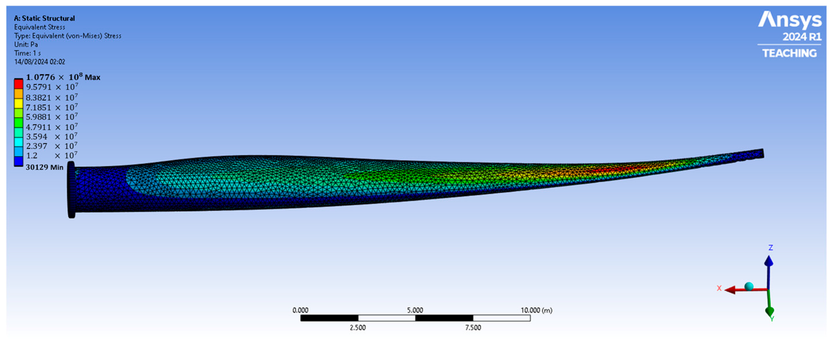
Figure 5 and Figure 6 demonstrate that the final geometry achieves a more even spread of stresses, avoiding localised peaks that could lead to premature failure. The retained material is strategically placed where bending moments and stresses are greatest, boosting safety margins.
In many practical settings, dealing with a blade for static load cases is more straightforward than ensuring certain dynamic properties (e.g., a 20% increase in natural frequency). For manufacturers and operators, ensuring that the blade will reliably meet deflection and stress criteria under real wind loads can be paramount.

4.4.2. Stress Distribution of the Static-Optimised Blade

Figure 5 illustrates the von Mises stress contour across the optimised blade. The highest stress concentrations (shown in red) remain confined near the blade root, where bending moments are greatest due to the cantilevered configuration. Along the blade’s leading and trailing edges—key load-bearing paths—moderate stress levels (in yellow to green) indicate that sufficient material has been retained to handle typical aerodynamic pressures and gust loads. Moving toward the mid-span and tip, the stress contour transitions into lower values (in blue), reflecting the judicious removal of internal volume where stresses are minimal.
Notably, Figure 5 also suggests a more uniform stress distribution when compared with the original, unoptimised model. By preserving material in regions subject to peak loads and eliminating it in low-stress zones, the optimiser ensures that no single area is overstressed beyond design limits.

4.4.3. Modal Analysis of the Static-Optimised Blade

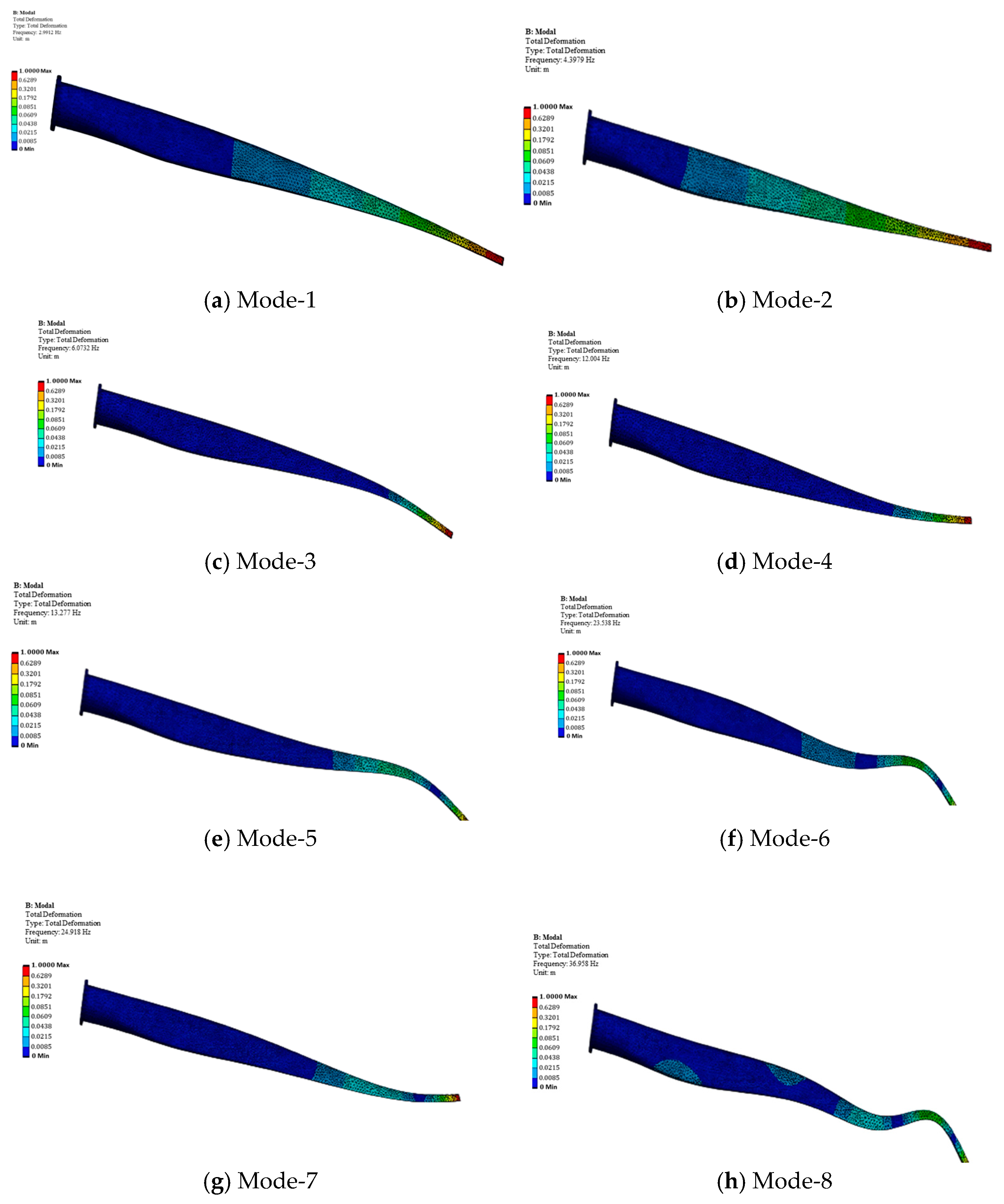
To evaluate dynamic performance, Figure 6 presents the first ten mode shapes, and Table 6 lists their corresponding natural frequencies. Each sub-figure in Figure 6 highlights a distinct vibrational pattern:
  • Mode 1 (2.9912 Hz)—Primarily a flapwise bending mode, indicative of the blade’s large aspect ratio and overall flexibility in the direction of aerodynamic loading.
  • Mode 2 (4.3979 Hz)—The first edgewise bending mode, representing in-plane flexibility due to gravitational and inertial effects.
  • Modes 3, 4, 5, 6, 7 (6.0732 Hz, 12.004 Hz, 13.277 Hz, 23.538 Hz, and 24.918 Hz)—Higher-order bending modes involving multiple nodal points, reflecting the dynamic response under more complex excitation patterns.
  • Modes 8, 9, 10 (36.958 Hz, 42.521 Hz, and 43.781 Hz)—Torsional modes, characterising twist deformation about the longitudinal axis, which is particularly relevant for aerodynamic stability and fatigue.
These natural frequencies span a broad range and can interact with several operational excitation sources. For instance, the rotational speed of 22.3 RPM corresponds to a frequency of approximately 0.37 Hz, which is well below the fundamental frequency and its harmonics. However, blade passing frequencies, turbine controller switching, and aerodynamic fluctuations due to wind shear or tower shadow effects can excite higher modes, particularly if they coincide with any of the modal frequencies. The separation between these natural frequencies and the typical excitation frequencies (i.e., ensuring no integer multiple alignment) is essential to prevent resonance and ensure safe long-term operation. The presence of distinct torsional and bending modes at higher frequencies suggests that the optimised blade design maintains sufficient dynamic stiffness, further contributing to vibrational safety and fatigue performance.

4.5. Final Remarks and Discussions

A recent study by Tüfekci et al., Ref. [46], also investigated topology optimisation strategies for composite wind turbine blades, focusing primarily on enhancing vibrational performance through modal-based objectives. Their work reported a comparable mass reduction (~49%) and a significant increase in the fundamental natural frequency by approximately 29%, supported by full mode shape characterisation for ten vibrational modes. While Tüfekci et al. placed emphasis on dynamic stiffness and resonance avoidance, the present study highlights that static-constraint-driven optimisation can also yield considerable improvements in mass efficiency and stiffness, with frequencies remaining within a safe operational range. Moreover, the results presented here show improved stress uniformity and material retention in critical regions such as the blade root, which may contribute to fatigue resistance. Together, these complementary studies reinforce the versatility of topology optimisation and its potential to tailor structural enhancements according to specific loading and performance requirements without compromising aerodynamic design.

5. Conclusions

This study has demonstrated that topology optimisation can be a valuable tool for improving the structural efficiency of composite wind turbine blades while achieving considerable mass reduction. By independently applying static and modal constraints, two complementary optimisation strategies were explored. The static-driven approach resulted in nearly 50% mass savings while preserving bending stiffness, retaining material in high-stress regions near the root, and promoting a more even stress distribution. This improved stress management may contribute to delaying fatigue initiation under operational loads. Furthermore, the design retained a fundamental natural frequency that remains within an acceptable range for safe operation in typical wind environments.
The modal-based optimisation increased the fundamental natural frequency by over 20%, thus offering improved dynamic stability and reduced risk of resonance. Material redistribution in this case enhanced both torsional and bending stiffness, and the resulting mass reduction was comparable to that of the statically optimised design. Both approaches successfully balanced mass efficiency, stress distribution, and vibrational integrity, highlighting the adaptability of topology optimisation for large-scale, composite structural components.
The results indicate that with appropriate constraint selection, substantial performance improvements can be achieved without altering the external aerodynamic profile. Tailoring the optimisation objective—towards deflection control or frequency enhancement—enables targeted reinforcement of critical load paths and the removal of structurally redundant material. This approach has the potential to support lighter, more efficient designs with better mechanical performance under operational demands.
Future work should focus on incorporating more advanced composite material models that capture anisotropy and damage progression, along with time-dependent phenomena such as fatigue and creep. Expanding the study to include transient loading scenarios—such as gusts or blade-passing events—would offer a more comprehensive assessment of operational reliability. Validation through physical testing, whether via scaled models or selected full-scale prototypes, will also be necessary to verify simulation outcomes. Additionally, further investigation into additive and hybrid manufacturing methods may help realise complex internal geometries in practice. Finally, life cycle assessments incorporating recyclability, embodied energy, and environmental footprint will be essential to evaluate the broader sustainability implications of topology-optimised blade designs.

Author Contributions

Conceptualisation, M.T.; methodology, M.T.; software, M.N.A.K.; validation, M.N.A.K. and M.T.; formal analysis, M.N.A.K.; investigation, M.N.A.K.; resources, M.N.A.K. and M.T.; data curation, M.N.A.K.; writing—original draft preparation, M.N.A.K.; writing—review and editing, M.T.; visualisation, M.N.A.K.; supervision, M.T.; project administration, M.T. All authors have read and agreed to the published version of the manuscript.

Funding

This research received no external funding.

Data Availability Statement

No new data were created or analyzed in this study. Data sharing is not applicable to this article.

Acknowledgments

The authors would like to sincerely thank İnci Pir for her contributions in improving the figures in this paper.

Conflicts of Interest

The authors declare no conflicts of interest.

References

  1. Buckney, N.; Pirrera, A.; Green, S.D.; Weaver, P.M. Structural Efficiency of a Wind Turbine Blade. Thin-Walled Struct. 2013, 67, 144–154. [Google Scholar] [CrossRef]
  2. Zhu, J.; Cai, X.; Ma, D.; Zhang, J.; Ni, X. Improved Structural Design of Wind Turbine Blade Based on Topology and Size Optimization. Int. J. Low-Carbon Technol. 2022, 17, 69–79. [Google Scholar] [CrossRef]
  3. Wang, Z.; Suiker, A.S.J.; Hofmeyer, H.; van Hooff, T.; Blocken, B. Coupled Aerostructural Shape and Topology Optimization of Horizontal-Axis Wind Turbine Rotor Blades. Energy Convers. Manag. 2020, 212, 112621. [Google Scholar] [CrossRef]
  4. Greeshma, V.S.; Rajakumar, S. Sravanthi Fatigue Analysis of Wind Turbine Blade for Various Materials. Mater. Today Proc. 2023. [Google Scholar] [CrossRef]
  5. Jayswal, S.; Bhattu, A. Structural and Modal Analysis of Small Wind Turbine Blade Using Three Different Materials. Mater. Today Proc. 2023, 72, 1347–1352. [Google Scholar] [CrossRef]
  6. Appadurai, M.; Raj, E.F.I. Finite Element Analysis of Composite Wind Turbine Blades. In Proceedings of the 7th International Conference on Electrical Energy Systems, ICEES 2021; IEEE: New York, NY, USA, 2021; pp. 585–589. [Google Scholar] [CrossRef]
  7. Gukendran, R.; Sambathkumar, M.; Sabari, C.; Raj, C.R.R.; Kumar, V.R. Structural Analysis of Composite Wind Turbine Blade Using ANSYS. Mater. Today Proc. 2021, 50, 1011–1016. [Google Scholar] [CrossRef]
  8. Krishnan, A.; Al-Obaidi, A.S.M.; Hao, L.C. A Comprehensive Review of Innovative Wind Turbine Airfoil and Blade Designs: Toward Enhanced Efficiency and Sustainability. Sustain. Energy Technol. Assess. 2023, 60, 103511. [Google Scholar] [CrossRef]
  9. Yirtici, O.; Tuncer, I.H. Aerodynamic Shape Optimization of Wind Turbine Blades for Minimizing Power Production Losses Due to Icing. Cold Reg. Sci. Technol. 2021, 185, 103250. [Google Scholar] [CrossRef]
  10. Shen, X.; Yang, H.; Chen, J.; Zhu, X.; Du, Z. Aerodynamic Shape Optimization of Non-Straight Small Wind Turbine Blades. Energy Convers. Manag. 2016, 119, 266–278. [Google Scholar] [CrossRef]
  11. Tüfekci, M.; Genel, Ö.E.; Tatar, A.; Tüfekci, E. Dynamic Analysis of Composite Wind Turbine Blades as Beams: An Analytical and Numerical Study. Vibration 2020, 4, 1–15. [Google Scholar] [CrossRef]
  12. Blasques, J.P.; Bitsche, R.D.; Fedorov, V.; Lazarov, B.S. Accuracy of an Efficient Framework for Structural Analysis of Wind Turbine Blades. Wind. Energy 2016, 19, 1603–1621. [Google Scholar] [CrossRef]
  13. Branner, K.; Blasques, J.P.; Kim, T.; Fedorov, V.A.; Berring, P.; Bitsche, R.D.; Berggreen, C.; Branner, K.; Blasques, J.P.; Kim, T.; et al. Anisotropic Beam Model for Analysis and Design of Passive Controlled Wind Turbine Blades; DTU Wind Energy: Roskilde, Denmark, 2012; Volume 0001. [Google Scholar]
  14. Tufekci, M.; Rendu, Q.; Yuan, J.; Dear, J.P.; Salles, L.; Cherednichenko, A.V. Stress and Modal Analysis of a Rotating Blade and the Effects of Nonlocality. In Proceedings of the ASME Turbo Expo; American Society of Mechanical Engineers: New York, NY, USA, 2020; Volume 10B-2020, pp. 1–12. [Google Scholar]
  15. Koç, H.; Genel, Ö.E.; Tüfekci, M.; Tüfekci, E. Analysis of the Dynamical Behaviour of Spinning Annular Disks with Various Boundary Conditions. Mech. Based Des. Struct. Mach. 2023, 51, 5427–5451. [Google Scholar] [CrossRef]
  16. Ullah, H.; Ullah, B.; Silberschmidt, V.V. Structural Integrity Analysis and Damage Assessment of a Long Composite Wind Turbine Blade under Extreme Loading. Compos. Struct. 2020, 246, 112426. [Google Scholar] [CrossRef]
  17. Devi, S.; Nagaraja, K.V. Enhanced Aerodynamic Performance of Wind Turbine Blades by Finite Element Meshing in Energy Applications. In Proceedings of the 2021 IEEE International Conference on Emerging Trends in Industry 4.0, ETI 4.0 2021, Raigarh, India, 19–21 May 2021; pp. 1–5. [Google Scholar] [CrossRef]
  18. Jeong, M.S.; Lee, I.; Yoo, S.J.; Park, K.C. Torsional Stiffness Effects on the Dynamic Stability of a Horizontal Axis Wind Turbine Blade. Energies 2013, 6, 2242–2261. [Google Scholar] [CrossRef]
  19. Roul, R.; Kumar, A. Fluid-Structure Interaction of Wind Turbine Blade Using Four Different Materials: Numerical Investigation. Symmetry 2020, 12, 1467. [Google Scholar] [CrossRef]
  20. Elsherif, D.M.; Abd El-Wahab, A.A.; Abdellatif, M.H. Factors Affecting Stress Distribution in Wind Turbine Blade. In Proceedings of the IOP Conference Series: Materials Science and Engineering; IOP Publishing: Philadelphia, PA, USA, 2019; Volume 610. [Google Scholar]
  21. Bechly, M.E.; Clausen, P.D. Structural Design of a Composite Wind Turbine Blade Using Finite Element Analysis. Comput. Struct. 1997, 63, 639–646. [Google Scholar] [CrossRef]
  22. Chiu, P.K.; Roth-Johnson, P.; Wirz, R.E. Optimal Structural Design of Biplane Wind Turbine Blades. Renew. Energy 2020, 147, 2440–2452. [Google Scholar] [CrossRef]
  23. Pal, A.; Bertoldi, K.; Pham, M.Q.; Schaenzer, M.; Gross, A.J. Optimal Turbine Blade Design Enabled by Auxetic Honeycomb. Smart Mater. Struct. 2020, 29, 125004. [Google Scholar] [CrossRef]
  24. Wood, R.J.K.; Lu, P. Leading Edge Topography of Blades-a Critical Review. Surf. Topogr. 2021, 9, 023001. [Google Scholar] [CrossRef]
  25. Mikkelsen, L.P. A Simplified Model Predicting the Weight of the Load Carrying Beam in a Wind Turbine Blade. IOP Conf. Ser. Mater. Sci. Eng. 2016, 139, 012038. [Google Scholar] [CrossRef]
  26. Baumgart, A. A Mathematical Model for Wind Turbine Blades. J. Sound. Vib. 2002, 251, 1–12. [Google Scholar] [CrossRef]
  27. Genel, Ö.E.; Tüfekci, E. Bending-Bending Coupled Static Analysis of Functionally Graded and Porous Pretwisted Cantilever Beams Using Initial Values Method. Mech. Based Des. Struct. Mach. 2023, 52, 2480–2503. [Google Scholar] [CrossRef]
  28. Genel, Ö.E.; Tüfekci, E. Axial–Torsional Coupled Static Behavior of Inhomogeneous Pretwisted Cantilever Beams. Acta Mech. 2023, 234, 3421–3436. [Google Scholar] [CrossRef]
  29. Fagan, E.M.; De La Torre, O.; Leen, S.B.; Goggins, J. Validation of the Multi-Objective Structural Optimisation of a Composite Wind Turbine Blade. Compos. Struct. 2018, 204, 567–577. [Google Scholar] [CrossRef]
  30. Jureczko, M.; Pawlak, M.; Mȩzyk, A. Optimisation of Wind Turbine Blades. J. Mater. Process Technol. 2005, 167, 463–471. [Google Scholar] [CrossRef]
  31. Vincekovic, L.; John, A.; Qin, N.; Shahpar, S. Exploring Topology Optimization for High Pressure Turbine Blade Tips. J. Turbomach. 2022, 144, 071013. [Google Scholar] [CrossRef]
  32. Song, J.; Chen, J.; Wu, Y.; Li, L. Topology Optimization-Driven Design for Offshore Composite Wind Turbine Blades. J. Mar. Sci. Eng. 2022, 10, 1487. [Google Scholar] [CrossRef]
  33. Han, P. Additive Design and Manufacturing of Jet Engine Parts. Engineering 2017, 3, 648–652. [Google Scholar] [CrossRef]
  34. Meng, J.; Liao, L.F.; Li, D.; Cao, Y.; Yang, L.Y.; Chen, Y.Y. Topology Optimization Method Research on Hollow Wide-Chord Fan Blade of a High-Bypass Turbofan Engine. Procedia Eng. 2015, 99, 1228–1233. [Google Scholar] [CrossRef]
  35. Barreau, V.; Denimal, E.; Salles, L. Topological Optimisation and 3D Printing of a Bladed Disc. In Proceedings of the ASME Turbo Expo; American Society of Mechanical Engineers: New York, NY, USA, 2022; Volume 8. [Google Scholar]
  36. Wei, J.; Zhang, Y.; Liu, Y.; Wang, Y.; Li, C.; Sun, Z.; Xu, H.; Shao, H.; Zhang, D.; Zou, Q.; et al. Advances in Resin Matrix Composite Fan Blades for Aircraft Engines: A Review. Thin-Walled Struct. 2024, 202, 112058. [Google Scholar] [CrossRef]
  37. Ahmad, F.; Kumar, P.; Patil, P.P.; Dobriyal, R.; Avikal, S. Comparative Analysis of Two and Four Blades Quadcopter Propellers Based on Finite Element Method. Mater. Today Proc. 2023. [Google Scholar] [CrossRef]
  38. Zhang, D.; Liu, Z.; Li, W.; Zhang, J.; Cheng, L.; Hu, G. Fluid-Structure Interaction Analysis of Wind Turbine Aerodynamic Loads and Aeroelastic Responses Considering Blade and Tower Flexibility. Eng. Struct. 2024, 301, 117289. [Google Scholar] [CrossRef]
  39. Luczak, M.; Manzato, S.; Peeters, B.; Branner, K.; Berring, P.; Kahsin, M. Updating Finite Element Model of a Wind Turbine Blade Section Using Experimental Modal Analysis Results. Shock. Vib. 2014, 2014, 684786. [Google Scholar] [CrossRef]
  40. Iddou, H.; Bouda, N.N.; Zereg, K. Computational Fluid Dynamics Study on the Efficiency of Straight-Bladed Vertical Axis Wind Turbine. Int. J. Thermofluids 2024, 22, 100672. [Google Scholar] [CrossRef]
  41. Ghafoorian, F.; Enayati, E.; Mirmotahari, S.R.; Wan, H. Self-Starting Improvement and Performance Enhancement in Darrieus VAWTs Using Auxiliary Blades and Deflectors. Machines 2024, 12, 806. [Google Scholar] [CrossRef]
  42. Ghafoorian, F.; Hosseini Rad, S.; Moghimi, M. Enhancing Self-Starting Capability and Efficiency of Hybrid Darrieus–Savonius Vertical Axis Wind Turbines with a Dual-Shaft Configuration. Machines 2025, 13, 87. [Google Scholar] [CrossRef]
  43. Farajyar, S.; Ghafoorian, F.; Mehrpooya, M.; Asadbeigi, M. CFD Investigation and Optimization on the Aerodynamic Performance of a Savonius Vertical Axis Wind Turbine and Its Installation in a Hybrid Power Supply System: A Case Study in Iran. Sustainability 2023, 15, 5318. [Google Scholar] [CrossRef]
  44. Chamran, S.; Ghafoorian, F.; Wan, H.; Chegini, S. A Systematic Analysis of a Small-Scale HAWT Configuration and Aerodynamic Performance Optimization Through Kriging, Factorial, and RSM Methods. J. Appl. Comput. Mech. 2025, 11, 887–903. [Google Scholar] [CrossRef]
  45. Tüfekci, M.; Öztekin, V.; Pir, İ.; Alioğlu, M.; Dikicioğlu, C.; Dikicioğlu, A.; Tüfekci, E. Low Strain Rate Mechanical Performance of Balsa Wood and Carbon Fibre-Epoxy-Balsa Sandwich Structures. Compos. Part. C Open Access 2023, 12, 100416. [Google Scholar] [CrossRef]
  46. Tüfekci, M.; Koçak, O.; Özkan, Y.; Pir, İ.; Tüfekci, E. Numerical Evaluation of Design Strategies for a Composite Wind Turbine Blade: Using Metallic Foams and Optimising Topology. Energy Sci. Eng. 2025, 13, 1457–1477. [Google Scholar] [CrossRef]
  47. Vieira, F.; Tüfekci, M.; Patel, S.; Pimenta, S. A Comprehensive Numerical Modelling of a Benchmark Wind Turbine Blade. In Proceedings of the ASME 2025 Aerospace Structures, Structural Dynamics, and Materials Conference; American Society of Mechanical Engineers: New York, NY, USA, 2025. [Google Scholar]
Figure 1. Wind turbine blade model.
Wind 05 00023 g001
Figure 2. Finalised mesh of the numerical model.
Wind 05 00023 g002
Figure 3. Topology-optimised internal structure of the blade based on static loading constraints. Material retention is concentrated near the root where bending stresses are highest, while significant internal cavities are formed along the mid-span and tip to reduce mass.
Wind 05 00023 g003
Figure 4. Topology-optimised internal structure of the blade based on modal (frequency) constraints. Material is retained in regions that contribute significantly to bending and torsional stiffness, particularly along the lengthwise edges, resulting in an efficient mass reduction without compromising dynamic performance.
Wind 05 00023 g004
Figure 5. Overall blade stress contour.
Wind 05 00023 g005
Figure 6. Mode shapes of the blade.
Wind 05 00023 g006aWind 05 00023 g006b
Table 1. Geometric dimensions and original mass of the wind turbine blade used in this study.
ParameterValue
Blade Length30.27 m
Root Diameter2.47 m
Original Mass4.553 × 105 kg
Table 2. Properties of a ply used in the composite shell of the blade.
PropertyValueUnits
Ply thickness0.327mm
Density1.76g/cm3
Fibre volume fraction~60%
Longitudinal modulus, E1141GPa
Transverse modulus, E28.7GPa
Shear modulus, G12, G135.6GPa
Shear modulus, G233.7GPa
Poisson’s ratio, ν12, ν130.3
Poisson’s ratio, ν230.4
Table 3. Mesh convergence study showing coupled convergence of displacement and natural frequency.
Mesh LevelMax. Element Size (m)No. of ElementsMax. Displacement (m)Relative Error Disp. (%)Fundamental Frequency (Hz)Relative Error Freq. (%)
10.515,2005.4 × 10−7 8.53.176
20.3531,6005.65 × 10−74.23.083
30.2547,9005.8 × 10−71.73.010.7
4 (Final)0.264,4105.9 × 10−702.990
Table 4. Preliminary tested values of total deformation.
Analysis Characteristics1st Test2nd Test3rd Test
Aero-pressure magnitude10,000 Pa20,000 Pa30,000 Pa
Total Deformation (Maximum)5.9004 × 10−71.1801 × 10−71.7701 × 10⁻⁶
Von Mises stress (Maximum)12,24224,48336,725
Maximum principle Elastic strain (Maximum)3.9426 × 10⁻⁸ m7.8851 × 10−8 m1.1828 × 10−7 m
Flapwise Direction Deformation (Maximum)4.0642 × 10⁻⁷ m8.1284 × 10−71.2193 × 10⁻⁷ m
Fundamental Natural Frequency2.3217 Hz2.3342 Hz2.3508 Hz
Table 5. Results of the topology optimisation procedures with static and modal constraints.
Static Topology ParametersResultsModal Topology ParametersResults
Original volume58 m3Original volume58 m3
Final volume29.757 m3Final volume29.47 m3
Reduced mass/volume percentage compared to the original mass/volume51.306Reduced mass/volume percentage compared to the original mass/volume50.81
Original mass4.553 × 105 kgOriginal mass4.553 × 105 kg
Final mass2.3359 × 105 kgFinal mass2.313 × 105 kg
Table 6. The natural frequencies of the first 10 modes.
Mode NumberFrequency (Hz)Description
Mode 12.99121st flapwise bending mode
Mode 24.39791st edgewise bending mode
Mode 36.07322nd flapwise bending mode
Mode 412.0042nd edgewise bending mode
Mode 513.2773rd flapwise bending mode
Mode 623.5383rd edgewise bending mode
Mode 724.9184th flapwise bending mode
Mode 836.9581st torsional mode
Mode 942.5212nd torsional mode
Mode 1043.7813rd torsional mode
Disclaimer/Publisher’s Note: The statements, opinions and data contained in all publications are solely those of the individual author(s) and contributor(s) and not of MDPI and/or the editor(s). MDPI and/or the editor(s) disclaim responsibility for any injury to people or property resulting from any ideas, methods, instructions or products referred to in the content.