
Shed Roof Air Extractors and Collectors: Design Guidelines for Natural Ventilation in Generic Models

 ,
,
Abstract
1. Introduction
2. Materials and Methods
2.1. Selection of Cases Analysed
2.2. Selection of Climatic Data
2.3. Computer Simulation
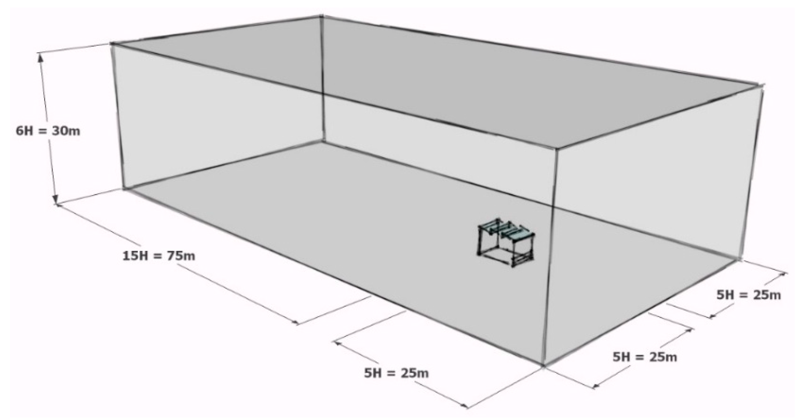
2.3.1. Model Generation
2.3.2. Computational Mesh Generation
2.3.3. Defining the Initial and Boundary Conditions
2.4. Analysis Parameters
3. Results
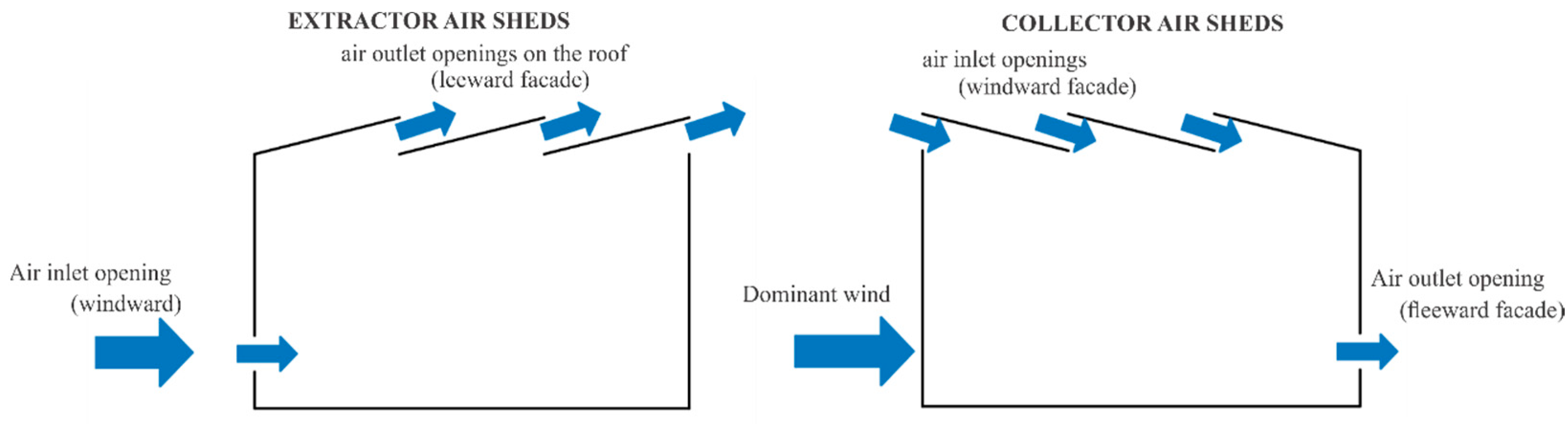
3.1. Design Guideline for the Use of the Shed Roof Air Extractors and Collector
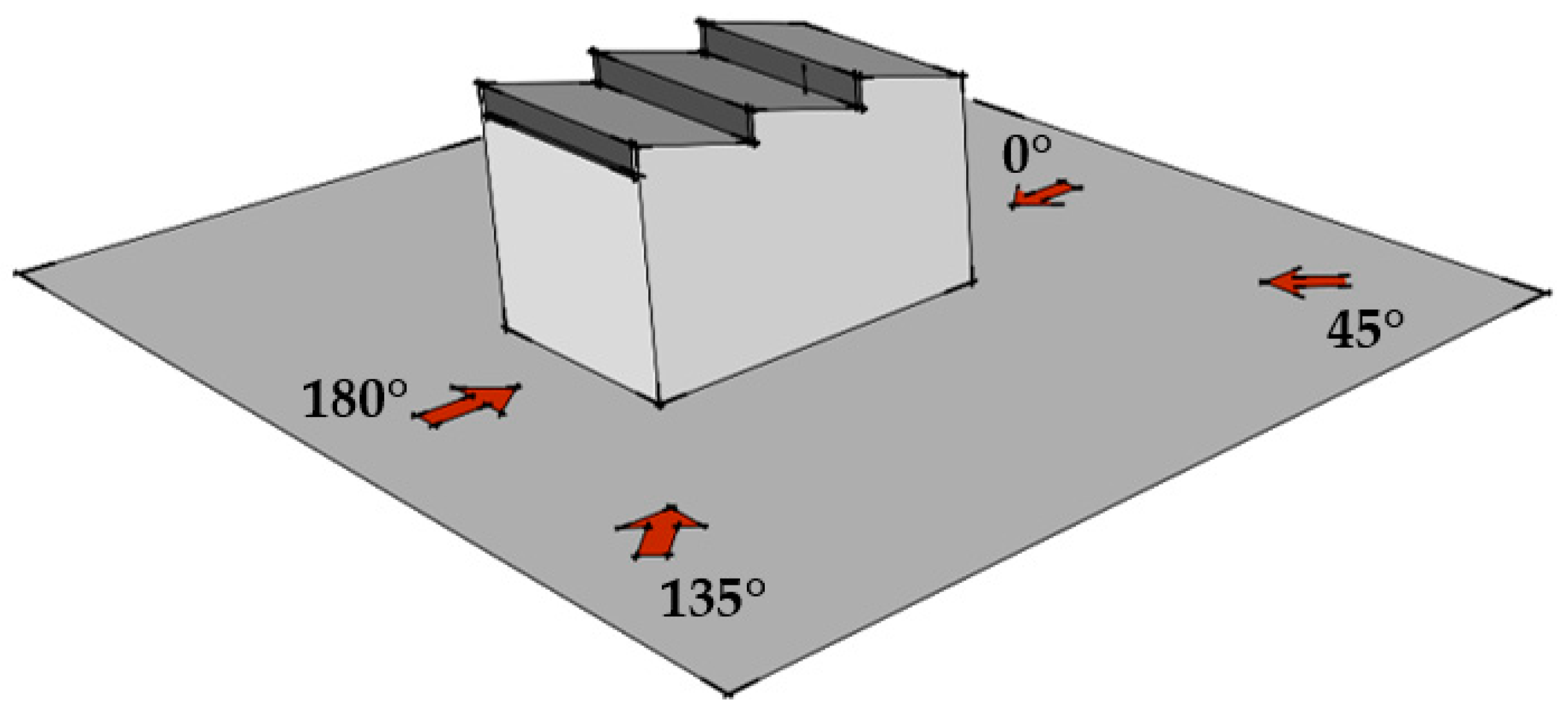
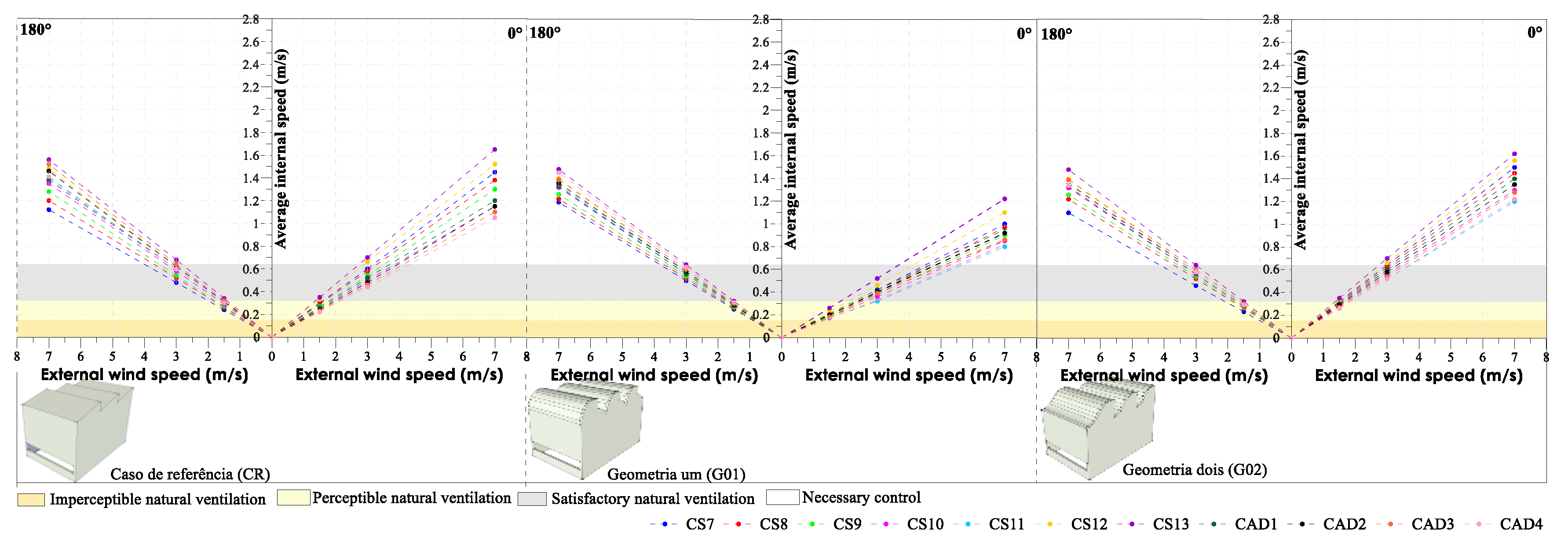
3.2. Design Recommendations Regarding the Velocity of External Winds
4. Conclusions
Author Contributions
Funding
Acknowledgments
Conflicts of Interest
References
- Royan, M.E.; Vaidya, P.; Mundhe, P. Teaching natural ventilation using water table apparatus: A classroom teaching, simulation and design tool. In PLEA 2018; The Chinese University of Hong Kong: Hong Kong, China, 2018. [Google Scholar]
- Mundhe, P.; Damle, R.M.; Vaidya, P.; Apte, M.G. Quantification of airflow patterns in a naturally ventilated building simulated in a water table apparatus. In PLEA 2018; The Chinese University of Hong Kong: Hong Kong, China, 2018. [Google Scholar]
- Buonanno, G.; Morawska, L.; Stabile, L. Quantitative assessment of the risk of airborne transmission of SARS-CoV-2 infection: Prospective and retrospective applications. Environ. Int. 2020, 145, 106112. [Google Scholar] [CrossRef]
- Miller, S.L.; Nazaroff, W.W.; Jimenez, J.L.; Boerstra, A.; Buonanno, G.; Dancer, S.J.; Kurnitski, J.; Marr, L.C.; Morawska, L.; Noakes, C. Transmission of SARS-CoV- 2 by inhalation of respiratory aerosol in the Skagit Valley Chorale superspreading event. Indoor Air 2020, 31, 314–323. [Google Scholar] [CrossRef] [PubMed]
- Prather, K.A.; Wang, C.C.; Schooley, R.T. Reducing transmission of SARS-CoV-2. Science 2020, 368, 1422–1424. [Google Scholar] [CrossRef] [PubMed]
- Tellier, R.; Li, Y.; Cowling, B.J.; Tang, J.W. Recognition of aerosol transmission of infectious agents: A commentary. BMC Infect. Dis. 2019, 19, 1–9. [Google Scholar] [CrossRef]
- Godwin, L.; Hayward, T.; Krishan, P.; Nolan, G.; Nundy, M.; Ostrishko, K.; Attili, A.; Cárceles, S.B.; Epelle, E.I.; Gabl, R.; et al. Which factors influence the extent of indoor transmission of SARS-CoV-2? A rapid evidence review. J. Glob. Health 2021, 11, 10002. [Google Scholar] [CrossRef]
- Vassela, C.C.; Koch, J.; Henzi, A.; Jordan, A.; Waeber, R.; Iannaccone, R.; Charrière, R. From spontaneous to strategic natural window ventilation: Improving indoor air quality in Swiss schools. Int. J. Hyg. Environ. Health 2021, 234, 113746. [Google Scholar] [CrossRef] [PubMed]
- Gettings, J.; Czarnik, M.; Morris, E.; Haller, E.; Thompson-Paul, A.M.; Rasberry, C.; Lanzieri, T.M.; Smith-Grant, J.; Aholou, T.M.; Thomas, E.; et al. Mask Use and Ventilation Improvements to Reduce COVID-19 Incidence in Elementary Schools—Georgia, November 16–December 11, 2020; Morbidity and Mortality Weekly Report; Centers for Disease Control and Prevention: Atlanta, GA, USA, 2021. [CrossRef]
- Zivelonghi, A.; Lai, M. Mitigating aerosol infection risk in school buildings: The role of natural ventilation, volume, occupancy and CO2 monitoring. Build. Environ. 2021, 204, 108139. [Google Scholar] [CrossRef]
- Dawson, P.; Worrell, M.C.; Malone, S.; Tinker, S.C.; Fritz, S.; Maricque, B.; Junaidi, S.; Purnell, G.; Lai, A.M.; Neidich, J.A.; et al. Pilot Investigation of SARS-CoV-2 Secondary Transmission in Kindergarten Through Grade 12 Schools Implementing Mitigation Strategies –St. Louis County and City of Springfield, Missouri, December 2020; Morbidity and Mortality Weekly Report; Centers for Disease Control and Prevention: Atlanta, GA, USA, 2021. [CrossRef]
- Cândido, C.; Lamberts, R.; Bittencourt, L.; Dear, R.J. Aplicabilidade dos limites de velocidade do ar para efeito de conforto térmico em climas quentes e úmidos. Rev. Ambiente Construído 2010, 10, 59–68. (In Portuguese) [Google Scholar] [CrossRef]
- Givoni, B. Man, Climate and Architecture; Applied Science Publishers: London, UK, 1976. [Google Scholar]
- Lamberts, R.; Dutra, L.; Pereira, F.O.R. Eficiência Energética na Arquitetura, 3rd ed.; PROCEL: Rio de Janeiro, Brazil, 2014. (In Portuguese) [Google Scholar]
- Neves, L.D.O.; Roriz, M. Procedimentos estimativos do potencial de uso de chaminés solares para promover a ventilação natural em edificações de baixa altura. Ambient. Constr. 2012, 12, 177–192. (In Portuguese) [Google Scholar] [CrossRef][Green Version]
- Afonso, C.; Oliveira, A. Solar Chimneys: Simulation and experiment. Energy Build. 2000, 32, 71–79. [Google Scholar] [CrossRef]
- Maerefat, M.; Haghighi, A.P. Passive Cooling of Buildings by Using Integrated Earth to Air Heat Exchanger and Solar Chimney. Renew. Energy 2010, 35, 2316–2324. [Google Scholar] [CrossRef]
- Bahadori, M.N.; Mazidi, M.; Dehghani, A.R. Experimental Investigation of New Designs of Wind Towers. Renew. Energy 2008, 33, 2273–2281. [Google Scholar] [CrossRef]
- Montazeri, H.; Azizian, R. Experimental Study on Natural Ventilation Performance of One-Sided Wind Catcher. Build. Environ. 2008, 43, 2193–2202. [Google Scholar] [CrossRef]
- Bittencourt, L.S.; da Silva Sacramento, A.; Cândido, C.; Leal, T. Estudo do desempenho do peitoril ventilado para aumentar a ventilação natural em escolas de Maceió/AL. Ambiente Construído 2007, 7, 59–69. (In Portuguese) [Google Scholar]
- Lukiantchuki, M.A.; Shimomura, A.P.; Marques da Silva, F.; Caram, R.M. Influência do número de sheds e da distância horizontal entre eles no desempenho da ventilação natural. Ambiente Construído 2018, 18, 161–176. [Google Scholar] [CrossRef]
- Lukiantchuki, M.A.; Shimomura, A.P.; Marques da Silva, F.; Caram, R.M. Wind tunnel and CFD analysis of wind-induced natural ventilation in sheds roof building: Impact of alignment and distance between sheds. Int. J. Vent. 2020, 19, 141–162. [Google Scholar] [CrossRef]
- Perén, J.I.; Hoof, T.; Leite, B.C.C.; Blocken, B. Impact of eaves on cross-ventilation of a generic isolated leeward sawtooth roof building: Windward eaves, leeward eaves and eaves inclination. Build. Environ. 2015, 92, 578–590. [Google Scholar] [CrossRef]
- Perén, J.I.; Hoof, T.; Leite, B.C.C.; Blocken, B. CFD simulation of wind-driven upward cross ventilation and its enhancement in long buildings: Impact of single-span versus double-span leeward sawtooth roof and opening ratio. Build. Environ. 2016, 96, 142–156. [Google Scholar] [CrossRef]
- Gandemer, J.; Barnaud, G. Ventilation naturelle dês habitations sous climat tropical humide: Aproach aerodynamique; CSTB; Pascal and Francis Bibliographic Databases: Nantes, France, 1989. [Google Scholar]
- Prevatt, D.O.; Cui, B. Wind tunnel studies on sawtooth and monosloped roofs. J. Struct. Eng. 2010, 136, 1161–1171. [Google Scholar] [CrossRef]
- Torres, D.; Adelino, T.; Bittencourt, L. Análise da utilização de sheds como estratégia passiva de ventilação em casa geminada. XII Encontro Nacional de Conforto no Ambiente Construído e VIII Encontro Latinoamericano de Conforto no Ambiente Construído. Anais de congresso. Brasília: ENCAC. CD-ROM, 2013. (In Portuguese)
- Stathopoulos, T.; Saathoff, P. Codification of wind pressure coefficients for sawtooth roofs. J. Wind. Eng. Ind. Aerodyn. 1992, 43, 1727–1738. [Google Scholar] [CrossRef]
- Stathopoulos, T.; Mohammadian, A.R. Wind loads on low buildings with mono-sloped roofs. J. Wind Eng. Ind. Aerodyn. 1985, 23, 81–97. [Google Scholar] [CrossRef]
- Holmes, J.D. Wind loading of multi-span. In Proceedings of the First National Structural Engineering Conference, Melbourne, Australia, 26–28 August 1987. [Google Scholar]
- Blackmore, P.A. Wind Loads on Pitch Roof Multi-Span Buildings. In Building Research Establishment; BRE Press: Bracknell, UK, 1986. [Google Scholar]
- Lukiantchuki, M.A.; Shimomura, A.P.; Marques da Silva, F.; Caram, R.M. Sheds extratores e captadores de ar: Influência da geometria e da dimensão das aberturas no desempenho da ventilação natural nas edificações. Ambiente Construído 2016, 16, 83–104. (In Portuguese) [Google Scholar] [CrossRef]
- Associação Brasileira de Normas Técnicas. ABNT NBR 15220-3: Desempenho Térmico de Edificações: Zoneamento Bioclimático Brasileiro e Diretrizes Construtivas para Habitações de Interesse Social; ABNT: Rio de Janeiro, Brazil, 2005. (In Portuguese) [Google Scholar]
- Roriz, M. Arquivos Climáticos de Municípios Brasileiros. Associação Nacional de Tecnologia do Ambiente Construído. Grupo de Trabalho sobre Conforto e Eficiência Energética de Edificações. Relatório Interno, 2012. Available online: http:www.labeee.ufsc.br/downloads/arquivos-climaticos (accessed on 12 May 2012). (In Portuguese).
- Lukiantchuki, M.A.; Shimomura, A.P.; Marques da Silva, F.; Caram, R.M. Evaluation of CGD simulations with wind tunnel experiments: Pressure coefficients at openings in sawtooth building. Acta Sci. Technol. 2018, 40, e37537. [Google Scholar] [CrossRef]
- COST. Cost Action 14: Recommendations on the Use of CFD in Predicting Pedestrian Wind Environment; COST: Brussels, Belgium, 2004. [Google Scholar]
- Tominaga, Y.; Mochida, A.; Murakami, S.; Sawaki, S. Comparasion of various revised k-e models and LES applied to flow around a high-rise building model with 1:1:2 shape placed within the surfasse boundary layer. J. Wind Eng. Ind. Aerodyn. 2008, 98, 65–78. [Google Scholar]
- Cóstola, D.; Alucci, M. Pressure Coefficient Simulated by CFD For Wind-Driven Ventilation Analysis. Proc. Build. Simul. 2007, 1, 999–1006. [Google Scholar]
- Calautit, J.K.; Hughes, B.R.; Chaudhry, H.N.; Ghani, S.A. CFD analysis of a heat transfer device integrated wind tower system for hot and dry climate. Appl. Energy 2013, 112, 576–591. [Google Scholar] [CrossRef]
- Hargreaves, D.M.; Morvan, H.P.; Wright, N.G. Validation of the Volume of Fluid Method for Free Surface Calculation: The broad-crested weir. Eng. Appl. Comput. Fluid Mech. 2014, 1, 136–146. [Google Scholar] [CrossRef]
- Balabel, A.; Faizan, M.; Alzaed, A. Towards a computational fluid dynamics-based fuzzy logic controller of the optimum windcatcher internal design for efficiente natural ventilation in buildings. Math. Probl. Eng. 2021, 2021, 9936178. [Google Scholar] [CrossRef]
- Gupta, D.; Khare, V.R. Natural ventilation design: Predicted and measured performance of a hostel building in composite climate of India. Energy Built Environ. 2021, 2, 82–93. [Google Scholar] [CrossRef]
- American Society of Heating, Refrigerating and Air Conditioning Engineers. ASHRAE Handbook Online: Fundamentals; ASHRAE: Atlanta, GA, USA, 2005. [Google Scholar]
- ISO 7726; Ergonomics of the Thermal Environment Instruments for Measuring Physical Quantities. International Organization for Standardization: Geneva, Switzerland, 1998.
- EUROCODE. In Eurocode 1: Actions on Structures—Part 1–4: General Actions—Wind Actions; The European Union Per Regulation 305/2011, Directive 98/34/EC, Directive 2004/18/EC; International Organization for Standardization: Geneva, Switzerland, 2010.


| Analyzed Geometry | |
|---|---|
| Geometry One (G01) | Geometry Two (G02) |
 |  |
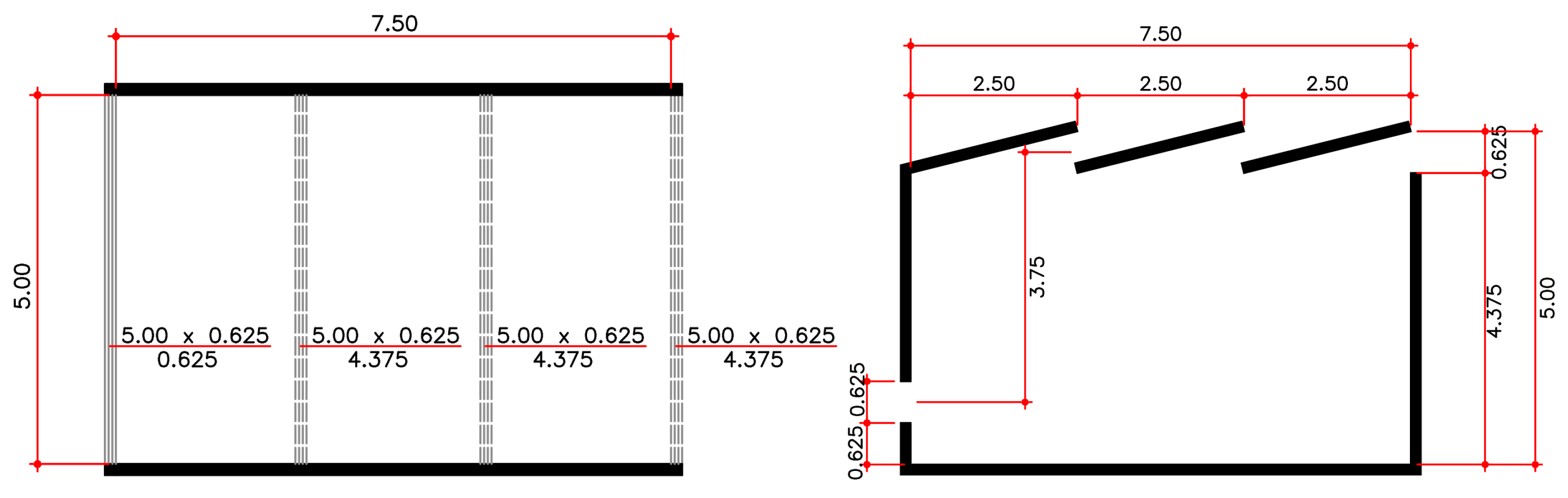
| Building size = 5.0 m × 7.5 m | Building size = 5.0 m × 7.5 m |
| Ceiling height of the building = 5.0 m | Ceiling height of the building = 5.0 m |
| N. sheds = 3 | N. sheds = 3 |
| Distance between sheds = 2.5 m | Distance between sheds = 2.5 m |
| Opening sizes = 0.625 m | Opening sizes = 0.625 m |
| Vertical distance between openings = 4.375 m | Vertical distance between openings = 4.375 m |
| Cases | Reference Case | Geometry One | Geometry Two |
|---|---|---|---|
| CA |  |  |  |
| N. sheds = 03 | N. sheds = 03 | N. sheds = 03 | |
| Opening height = 0.625 m | Opening height = 0.625 m | Opening height = 0.625 m | |
| Opening area = 3.12 m2 | Opening area = 3.12 m2 | Opening area = 3.12 m2 | |
| Sheds height = 0.625 m | Sheds height = 0.625 m | Sheds height = 0.625 m | |
| Sheds Total Area = 9.375 m2 | Sheds Total Area = 9.375 m2 | Sheds Total Area = 9.375 m2 | |
| CA1 |  |  |  |
| N. sheds = 03 | N. sheds = 03 | N. sheds = 03 | |
| Opening height = 0.9375 m | Opening height = 0.9375 m | Opening height = 0.9375 m | |
| Opening area = 4.68 m2 | Opening area = 4.68 m2 | Opening area = 4.68 m2 | |
| Sheds height = 0.625 m | Sheds height = 0.625 m | Sheds height = 0.625 m | |
| Sheds Total Area = 9.375 m2 | Sheds Total Area = 9.375 m2 | Sheds Total Area = 9.375 m2 | |
| CA2 |  |  |  |
| N. sheds = 03 | N. sheds = 03 | N. sheds = 03 | |
| Opening height = 1.25 m | Opening height = 1.25 m | Opening height = 1.25 m | |
| Opening area = 6.25 m2 | Opening area = 6.25 m2 | Opening area = 6.25 m2 | |
| Sheds height = 0.625 m | Sheds height = 0.625 m | Sheds height = 0.625 m | |
| Sheds Total Area = 9.375 m2 | Sheds Total Area = 9.375 m2 | Sheds Total Area = 9.375 m2 | |
| CS1 |  |  |  |
| N. sheds = 03 | N. sheds = 03 | N. sheds = 03 | |
| Opening height = 0.625 m | Opening height = 0.625 m | Opening height = 0.625 m | |
| Opening area = 3.12 m2 | Opening area = 3.12 m2 | Opening area = 3.12 m2 | |
| Sheds height = 0.937 m | Sheds height = 0.937 m | Sheds height = 0.937 m | |
| Sheds Total Area = 14.062 m2 | Sheds Total Area = 14.062 m2 | Sheds Total Area = 14.062 m2 | |
| CS2 |  |  |  |
| N. sheds = 03 | N. sheds = 03 | N. sheds = 03 | |
| Opening height = 0.625 m | Opening height = 0.625 m | Opening height = 0.625 m | |
| Opening area = 3.12 m2 | Opening area = 3.12 m2 | Opening area = 3.12 m2 | |
| Sheds height = 1.25 m | Sheds height = 1.25 m | Sheds height = 1.25 m | |
| Sheds Total Area = 18.75 m2 | Sheds Total Area = 18.75 m2 | Sheds Total Area = 18.75 m2 |
| Cases | Reference Case | Geometry One | Geometry Two |
|---|---|---|---|
| CS7 |  |  |  |
| Model size = 5.0 m × 17.5 m | |||
| N. sheds = 07 | |||
| Distance between sheds = 2.50 m | |||
| Sheds height = 0.625 m | |||
| Sheds Total Area = 21.875 m2 | |||
| CS8 |  |  |  |
| Model size = 5.0 m × 17.5 m | |||
| N. sheds = 05 | |||
| Distance between sheds = 3.75 m | |||
| Sheds opening height = 0.625 m | |||
| Sheds Total Area = 15.325 m2 | |||
| CS9 |  |  |  |
| Model size = 5.0 m × 17.5 m | |||
| N. sheds = 04 | |||
| Distance between sheds = 5.00 m | |||
| Sheds opening height = 0.625 m | |||
| Sheds Total Area = 12.5 m2 | |||
| CS10 |  |  |  |
| Model size = 5.0 m × 17.5 m | |||
| N. sheds = 03 | |||
| Distance between sheds = 7.50 m | |||
| Sheds opening height = 0.625 m | |||
| Sheds Total Area = 9.375 m2 | |||
| CS11 |  |  |  |
| Model size = 5.0 m × 17.5 m | |||
| N. sheds = 02 | |||
| Distance between sheds = 15.0 m | |||
| Sheds opening height = 0.625 m | |||
| Sheds Total Area = 6.25 m2 | |||
| CS12 |  |  |  |
| Model size = 5.0 m × 17.5 m | |||
| N. sheds = 04 | |||
| Distance between sheds = 5.00 m | |||
| Sheds opening height = 1.0937 m | |||
| Sheds Total Area = 21.875 m2 | |||
| CS13 |  |  |  |
| Model size = 5.0 m × 17.5 m | |||
| N. sheds = 03 | |||
| Distance between sheds = 7.50 m | |||
| Sheds opening height = 1.4583 m | |||
| Sheds Total Area = 21.875 m2 | |||
| CAD1 |  |  |  |
| Model size = 5.0 m × 17.5 m | |||
| N. sheds = 07 | |||
| Distance between sheds = 2.50 m | |||
| Sheds opening height = 0.625 m | |||
| Sheds Total Area = 10.9375 m2 | |||
| CAD2 |  |  |  |
| Model size = 5.0 m × 17.5 m | |||
| N. sheds = 04 | |||
| Distance between sheds = 5.00 m | |||
| Sheds opening height = 0.625 m | |||
| Sheds Total Area = 6.25 m2 | |||
| CAD3 |  |  |  |
| Model size = 5.0 m × 17.5 m | |||
| N. sheds = 03 | |||
| Distance between sheds = 7.50 m | |||
| Sheds opening height = 0.625 m | |||
| Sheds Total Area = 4.6875 m2 | |||
| CAD4 |  |  |  |
| Model size = 5.0 m × 17.5 m | |||
| N. sheds = 06 | |||
| Distance between sheds = 5.00 m | |||
| Sheds opening height = 0.625 m | |||
| Sheds Total Area = 6.25 m2 | |||
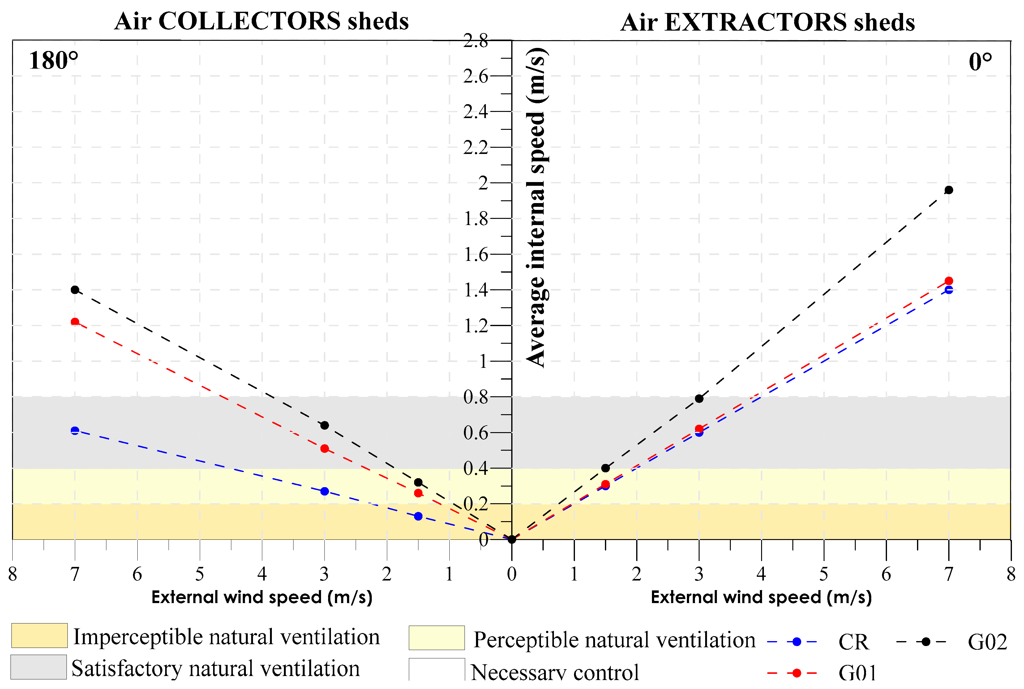
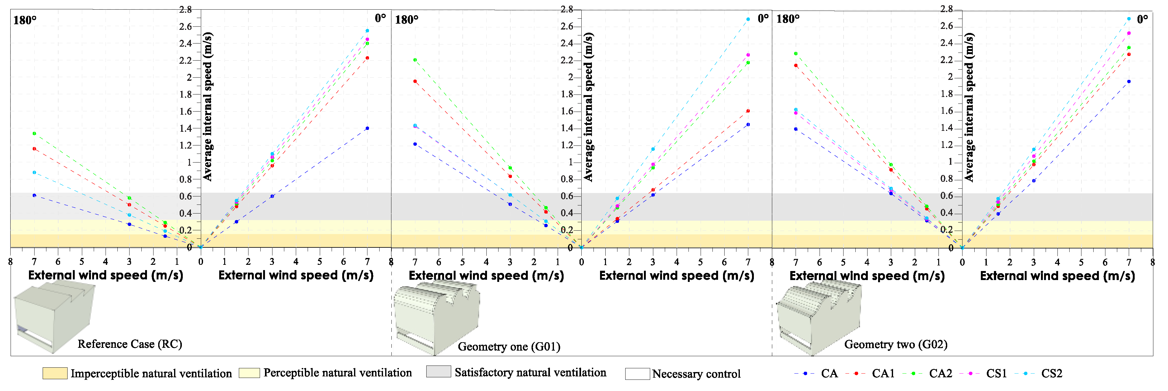
| Air Velocity (m/s) | Situation Occurred |
|---|---|
| 0–0.2 | Imperceptible natural ventilation |
| 0.2–0.4 | Perceptible natural ventilation |
| 0.4–0.8 | Satisfactory natural ventilation (there is a reduction in thermal load and contributes to comfort) |
| Above 0.8 | Control is necessary (discomforts such as lifting papers, objects disorder) |
| Design Parameter 01: SHEDS GEOMETRY | ||
|---|---|---|
| Air EXTRACTOR Sheds | Shed Roof Air EXTRACTORS and COLLECTORS | Shed Roof Air EXTRACTORS and COLLECTORS |
 |  |  |
Based on Lukiantchuki et al. (2016) [32], we have the best performance:
| ||
| Design Parameter 02: SIZE OF AIR INLET AND OUTLET OPENINGS | ||
|---|---|---|
| Air EXTRACTOR Sheds | Air COLLECTOR Sheds | Shed Roof Air EXTRACTORS and COLLECTORS |
 |  |  |
Based on Lukiantchuki et al. (2016) [32], we have the best performance:
| ||
| Design Parameter 03: NUMBER OF SHEDS IN THE ROOF | ||
|---|---|---|
| Air EXTRACTOR Sheds | Air COLLECTOR Sheds | Shed roof air EXTRACTORS and COLLECTORS |
 |  |  |
Based on Lukiantchuki et al. (2018) [21], we have the best performance:
| ||
| Design Parameter 04: SIZE OF THE SHEDS AND DISTANCE BETWEEN THESE ELEMENTS | ||
|---|---|---|
| Air EXTRACTOR Sheds | Air COLLECTOR Sheds | Air EXTRACTORS and COLLECTORS |
 |  |  |
Based on Lukiantchuki et al. (2019) [22], we have:
| ||
| SHED ROOF AIR EXTRACTORS | |||
|---|---|---|---|
| CLASSIFICATION | 1.5 m/s | 3.0 m/s | 7.0 m/s |
| IMPERCEPTIBLE | Group 01: CR and G01 Group 03: buildings with greater depth; increasing the distance between the sheds and the misalignment of the sheds. | -------- | -------- |
| PERCEPTIBLE | -------- | -------- | -------- |
| SATISFACTORY | Group 01: G02 Group 02: increase in the size of the air inlet and outlet openings | Group 01: CR, G01, G02 Group 03: sheds close to each other; insert the sheds in 2 rows, without increasing the distance between them too much; if the distance between these devices increases, the air outlet openings must be increased, which increases internal ventilation, making it satisfactory for achieving comfort | -------- |
| CONTROL | -------- | Group 02: increase in the size of the air inlet and outlet openings | Group 01: all cases Group 02: all cases Group 03: all cases |
| SHED ROOF AIR COLLECTORS | |||
| 1.5 m/s | 3.0 m/s | 7.0 m/s | |
| IMPERCEPTIBLE | Group 01: CR Group 02: the increase in air inlet and outlet openings increased the velocity of the indoor airflow, but even so, the CR remained with unsatisfactory natural ventilation. Group 03: buildings with greater depth; increase the distance between the sheds and the misalignment of the sheds | Group 01: CR Group 02: increase in air inlet openings (sheds) Group 03: all cases are enough to reduce the thermal load and provide thermal comfort for users. | -------- |
| PERCEPTIBLE | Group 01: G01 and G02 | -------- | -------- |
| SATISFACTORY | Group 02: G01 and G02, with the increase in the air outlet opening users are comfortable | Group 01: G01 and G02 Group 02: increase in the size of the air outlet openings | -------- |
| CONTROL | -------- | -------- | Group 01: all cases Group 02: all cases Group 03: all cases |
Disclaimer/Publisher’s Note: The statements, opinions and data contained in all publications are solely those of the individual author(s) and contributor(s) and not of MDPI and/or the editor(s). MDPI and/or the editor(s) disclaim responsibility for any injury to people or property resulting from any ideas, methods, instructions or products referred to in the content. |
© 2023 by the authors. Licensee MDPI, Basel, Switzerland. This article is an open access article distributed under the terms and conditions of the Creative Commons Attribution (CC BY) license (https://creativecommons.org/licenses/by/4.0/).
Share and Cite
Lukiantchuki, M.A.; Shimomura, A.R.P.; Silva, F.M.d.; Caram, R.M. Shed Roof Air Extractors and Collectors: Design Guidelines for Natural Ventilation in Generic Models. Wind 2023, 3, 170-190. https://doi.org/10.3390/wind3020011
Lukiantchuki MA, Shimomura ARP, Silva FMd, Caram RM. Shed Roof Air Extractors and Collectors: Design Guidelines for Natural Ventilation in Generic Models. Wind. 2023; 3(2):170-190. https://doi.org/10.3390/wind3020011
Chicago/Turabian StyleLukiantchuki, Marieli Azoia, Alessandra Rodrigues Prata Shimomura, Fernando Marques da Silva, and Rosana Maria Caram. 2023. "Shed Roof Air Extractors and Collectors: Design Guidelines for Natural Ventilation in Generic Models" Wind 3, no. 2: 170-190. https://doi.org/10.3390/wind3020011
APA StyleLukiantchuki, M. A., Shimomura, A. R. P., Silva, F. M. d., & Caram, R. M. (2023). Shed Roof Air Extractors and Collectors: Design Guidelines for Natural Ventilation in Generic Models. Wind, 3(2), 170-190. https://doi.org/10.3390/wind3020011