
Maintenance and End-of-Life Analysis in LCA for Barge-Type Floating Wind Turbine


Abstract
:1. Introduction
- To assess the environmental impacts of on-site and onshore maintenance scenarios for a barge-type floating wind turbine.
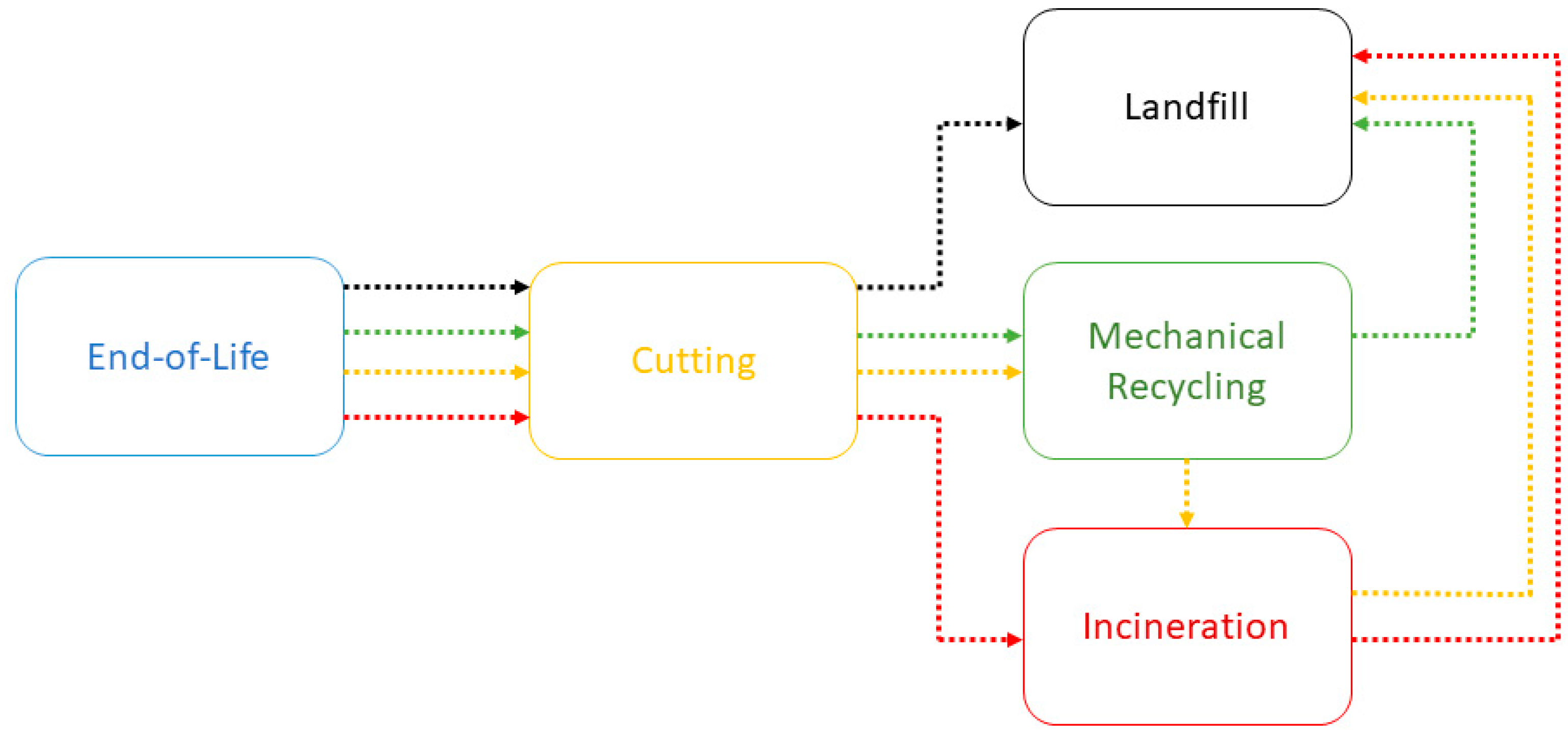
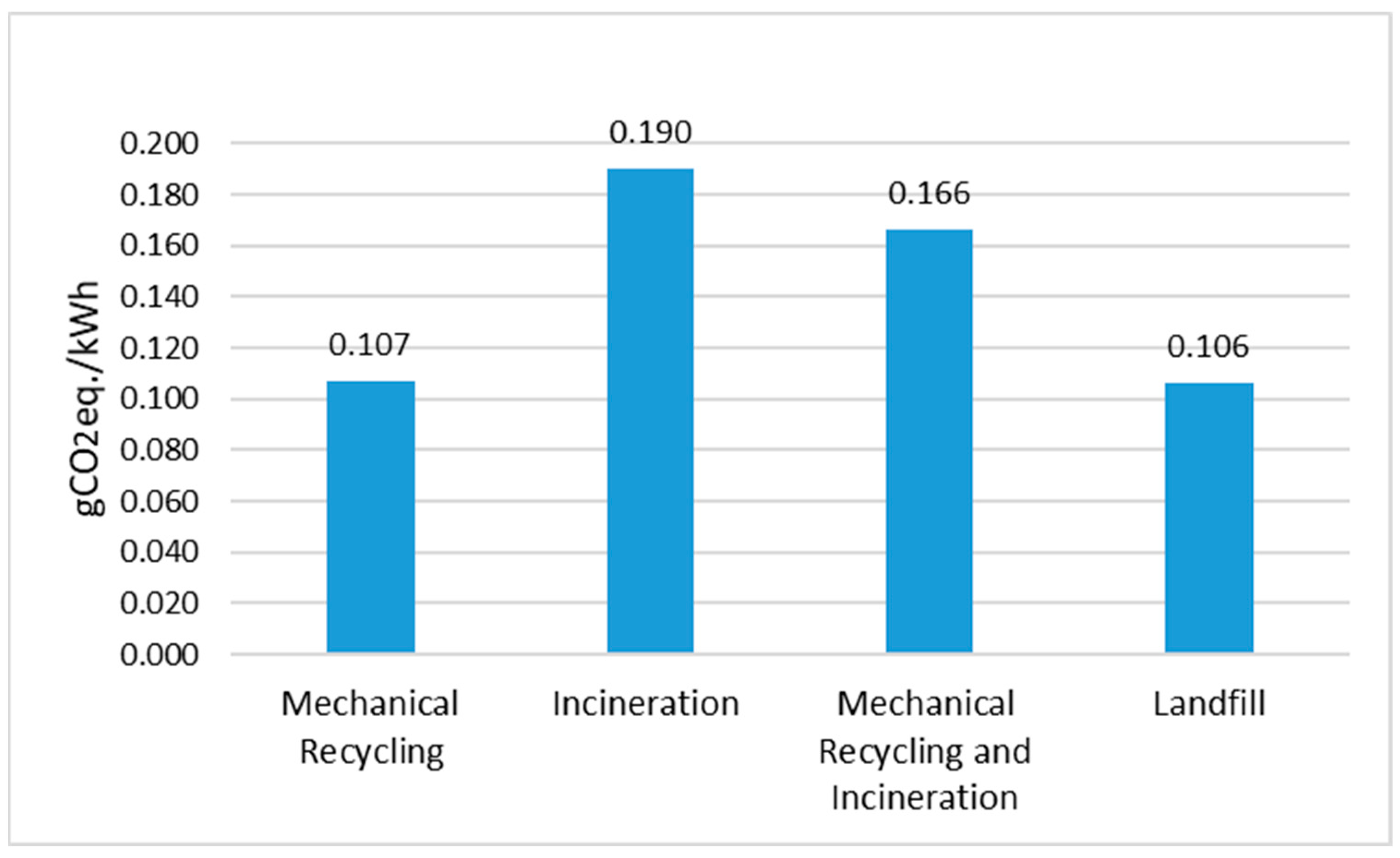
- To investigate the environmental impacts of composite material mechanical recycling, mechanical-incineration, and incineration processes.
- To reduce the environmental impact of barge-type floating wind turbines, taking maintenance and end-of-life scenarios into account.
2. Methods
The Barge-Type Floating Wind Turbine
3. Wind Turbine Maintenance
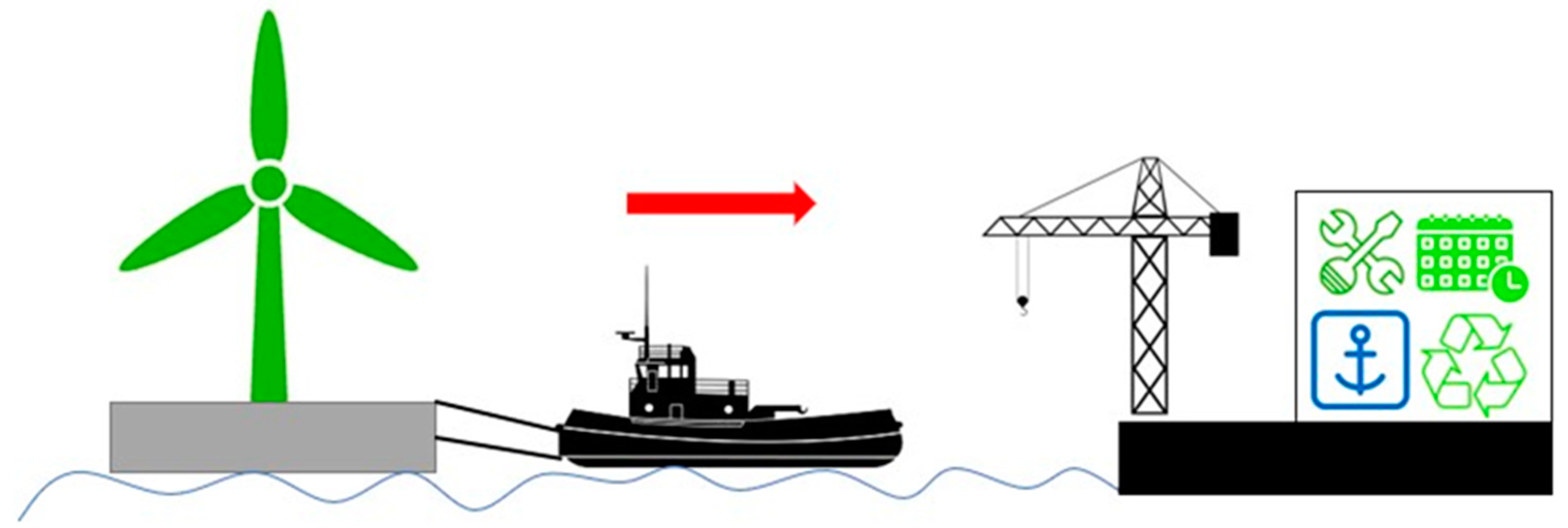
Maintenance Scenarios
4. End-of-Life Scenarios
5. Analysed Scenarios and Results
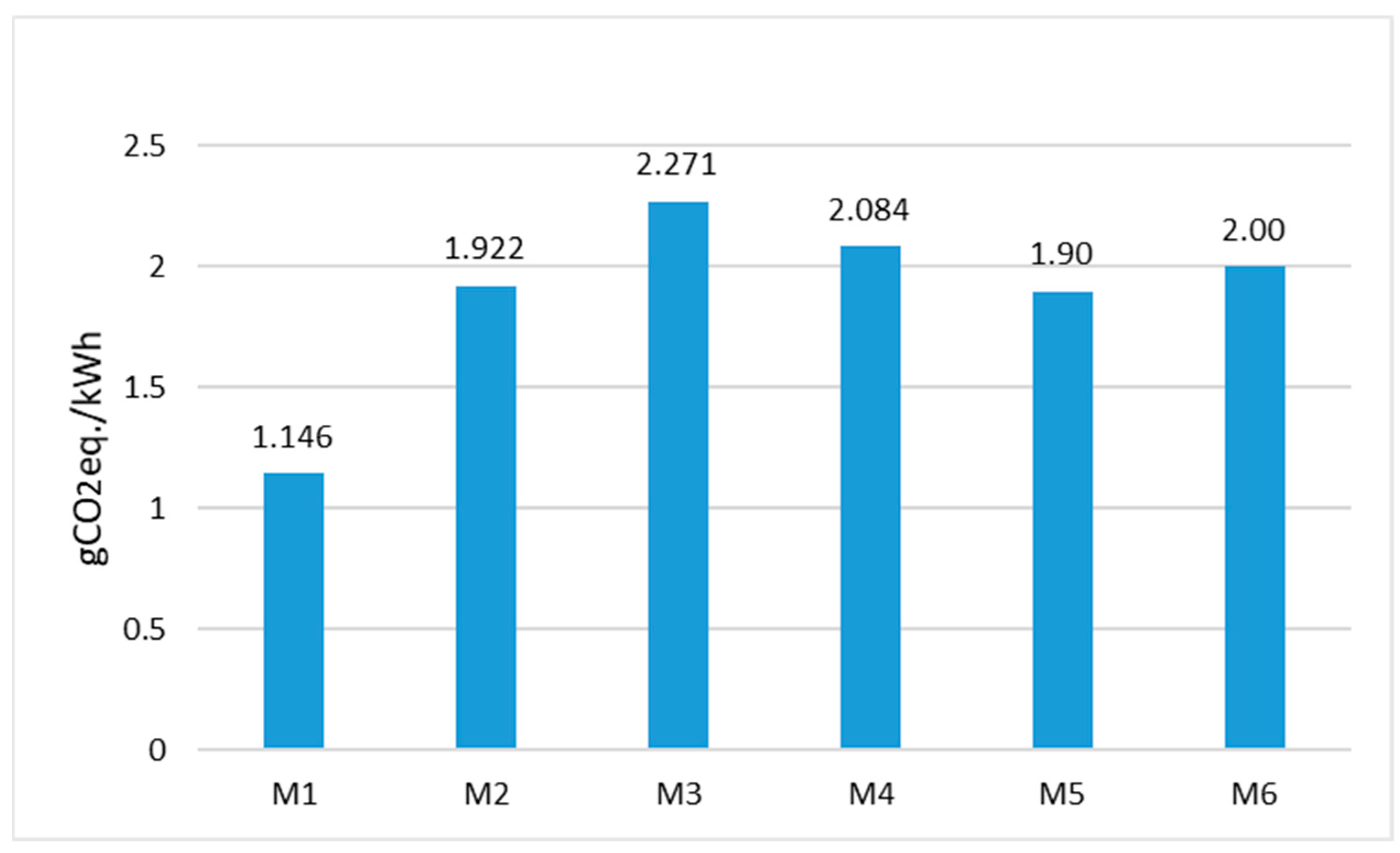
5.1. Maintenance Scenario Results
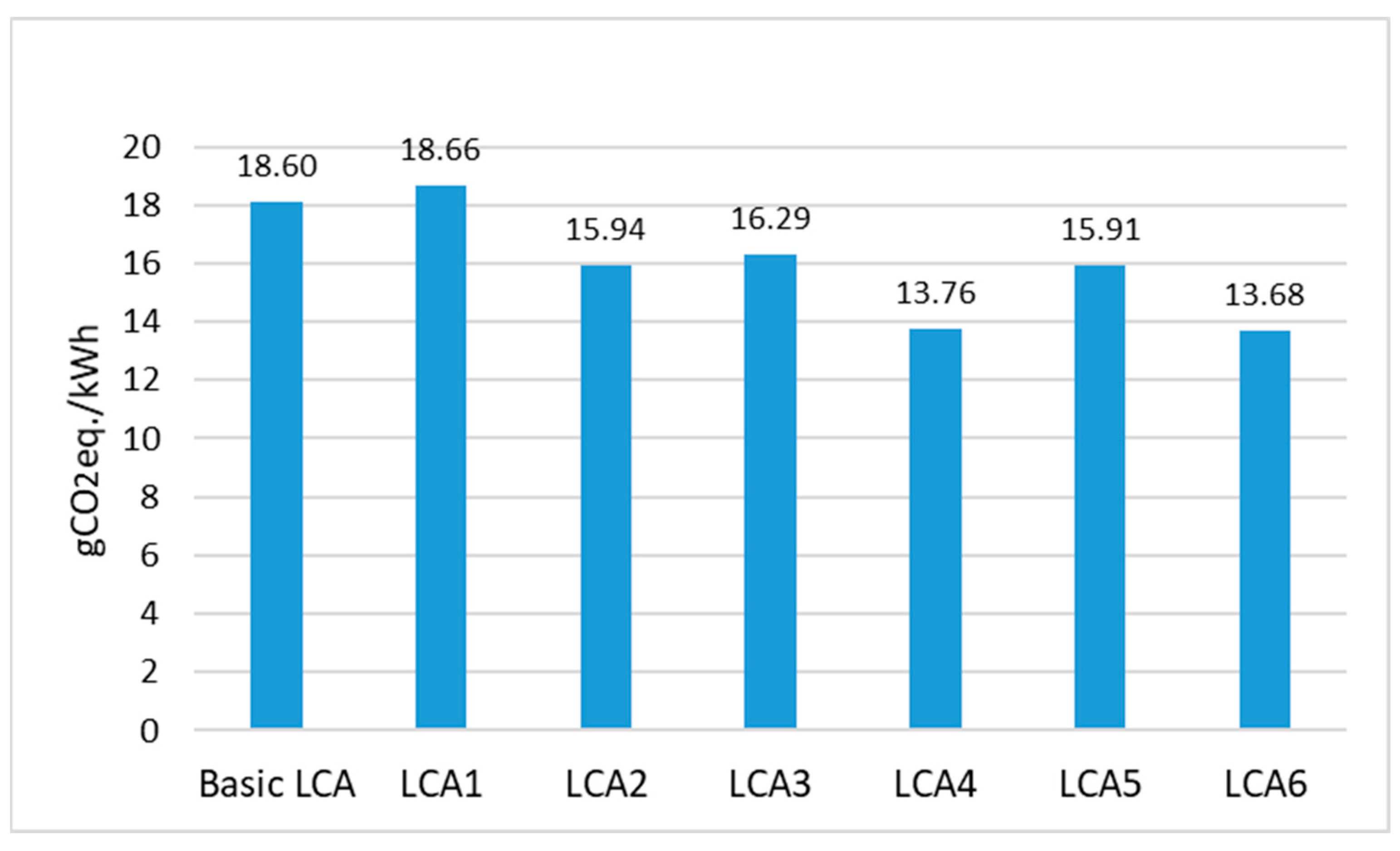
5.2. End-of-Life Scenario Results
6. Conclusions
- The environmental impacts of these scenarios might be examined in more depth, such as acidification potential, abiotic depletion potential for fossil fuels, etc.
- The energy payback time of these scenarios should be addressed.
- Only the CO2 emissions of these scenarios were evaluated in comparison in this study. Nevertheless, the costs of these scenarios could well be computed, and a comprehensive comparison could be performed.
Author Contributions
Funding
Institutional Review Board Statement
Informed Consent Statement
Data Availability Statement
Acknowledgments
Conflicts of Interest
References
- Andersen, N.; Eriksson, O.; Hillman, K.; Wallhagen, M. Wind Turbines’ End-of-Life: Quantification and Characterisation of Future Waste Materials on a National Level. Energies 2016, 9, 999. [Google Scholar] [CrossRef] [Green Version]
- Unfccc.int. 2021. Available online: https://unfccc.int/conference/glasgow-climate-change-conference-october-november-2021 (accessed on 19 November 2021).
- Farina, A.; Anctil, A. Material consumption and environmental impact of wind turbines in the USA and globally. Resour. Conserv. Recycl. 2021, 176, 105938. [Google Scholar] [CrossRef]
- Heng, H.; Meng, F.; McKechnie, J. Wind turbine blade wastes and the environmental impacts in Canada. Waste Manag. 2021, 133, 59–70. [Google Scholar] [CrossRef]
- World Wind Energy Association. World Wind Capacity, World Wind Energy Association. 2021. Available online: https://wwindea.org/world-wind-capacity-at-650-gw/ (accessed on 20 January 2021).
- Wind Energy. Country. 2019. Available online: https://www.power-technology.com (accessed on 15 January 2021).
- Wind in Europe. European Statistical Data Support. 2019. Available online: https://windeurope.org/ (accessed on 10 January 2021).
- Martin, R. Floating Wind Turbines Could Provide Huge Amounts of Clean Power—If They Can Ever Compete on Cost. MIT Technology Review. 2020. Available online: https://www.technologyreview.com/s/601481/floating-wind-farms-great-concept-implausible-economics/ (accessed on 12 January 2021).
- Gervasio, H.; Rebelo, C.; Moura, A.; Veljkovic, M.; Simoesdasilva, L. Comparative life cycle assessment of tubular wind towers and foundations—Part 2: Life cycle analysis. Eng. Struct. 2014, 74, 292–299. [Google Scholar] [CrossRef]
- Tremeac, B.; Meunier, F. Life cycle analysis of 4.5 MW and 250 W wind turbines. Renew. Sustain. Energy Rev. 2009, 13, 2104–2110. [Google Scholar] [CrossRef]
- Alsaleh, A.; Sattler, M. Comprehensive life cycle assessment of large wind turbines in the US. Clean Technol. Environ. Policy 2019, 21, 887–903. [Google Scholar] [CrossRef]
- Stavridou, N.; Koltsakis, E.; Baniotopoulos, C.C. A comparative life-cycle analysis of tall onshore steel wind-turbine towers. Clean Energy 2019, 4, 48–57. [Google Scholar] [CrossRef]
- Gkantou, M.; Rebelo, C.; Baniotopoulos, C. Life Cycle Assessment of Tall Onshore Hybrid Steel Wind Turbine Towers. Energies 2020, 13, 3950. [Google Scholar] [CrossRef]
- Weinzettel, J.; Reenaas, M.; Solli, C.; Hertwich, E.G. Life cycle assessment of a floating offshore wind turbine. Renew. Energy 2009, 34, 742–747. [Google Scholar] [CrossRef]
- Raadal, H.L.; Vold, B.I.; Myhr, A.; Nygaard, T.A. GHG emissions and energy performance of offshore wind power. Renew. Energy 2014, 66, 314–324. [Google Scholar] [CrossRef]
- Eligoz, N.; Bas, B. Life Cycle Assessment of a multi-use offshore platform: Combining wind and wave energy production. Ocean. Eng. 2017, 145, 430–443. [Google Scholar]
- Kausche, M.; Adam, F.; Dahlhaus, F.; Großmann, J. Floating offshore wind-Economic and ecological challenges of a TLP solution. Renew. Energy 2018, 126, 270–280. [Google Scholar] [CrossRef]
- Yildiz, N.; Hemida, H.; Baniotopoulos, C. Life Cycle Assessment of a Barge-Type Floating Wind Turbine and Comparison with Other Types of Wind Turbines. Energies 2021, 14, 5656. [Google Scholar] [CrossRef]
- Bonou, A.; Laurent, A.; Olsen, S.I. Life cycle assessment of onshore and offshore wind energy-from theory to application. Appl. Energy 2016, 180, 327–337. [Google Scholar] [CrossRef] [Green Version]
- Xu, L.; Pang, M.; Zhang, L.; Poganietz, W.-R.; Marathe, S.D. Life cycle assessment of onshore wind power systems in Chi-na. Resour. Conserv. Recycl. 2018, 132, 361–368. [Google Scholar] [CrossRef]
- Chipindula, J.; Botlaguduru, V.S.V.; Du, H.; Kommalapati, R.R.; Huque, Z. Life Cycle Environmental Impact of Onshore and Offshore Wind Farms in Texas. Sustainability 2018, 10, 2022. [Google Scholar] [CrossRef] [Green Version]
- Demir, N.; Taşkın, A. Life cycle assessment of wind turbines in Pınarbaşı-Kayseri. J. Clean. Prod. 2013, 54, 253–263. [Google Scholar] [CrossRef]
- Al-Behadili, S.; El-Osta, W. Life Cycle Assessment of Dernah (Libya) wind farm. Renew. Energy 2015, 83, 1227–1233. [Google Scholar] [CrossRef]
- Oebels, K.B.; Pacca, S. Life cycle assessment of an onshore wind farm located at the northeastern coast of Brazil. Renew. Energy 2013, 53, 60–70. [Google Scholar] [CrossRef]
- Properzi, S.; Herk-Hansen, H. Life cycle assessment of a 150 MW offshore wind turbine farm at Nysted/Roedsand, Denmark. Int. J. Environ. Sustain. Dev. 2002, 1, 113. [Google Scholar] [CrossRef]
- Lenzen, M.; Wachsmann, U. Wind turbines in Brazil and Germany: An example of geographical variability in life-cycle assessment. Appl. Energy 2004, 77, 119–130. [Google Scholar] [CrossRef]
- Kasner, R.; Kruszelnicka, W.; Bałdowska-Witos, P.; Flizikowski, J.; Tomporowski, A. Sustainable Wind Power Plant Modern-ization. Energies 2020, 13, 1461. [Google Scholar] [CrossRef] [Green Version]
- Nagle, A.J.; Delaney, E.L.; Bank, L.C.; Leahy, P.G. A Comparative Life Cycle Assessment between landfilling and Co-Processing of waste from decommissioned Irish wind turbine blades. J. Clean. Prod. 2020, 277, 123321. [Google Scholar] [CrossRef]
- Martínez, E.; Jiménez, E.; Blanco, J.; Sanz, F. LCA sensitivity analysis of a multi-megawatt wind turbine. Appl. Energy 2010, 87, 2293–2303. [Google Scholar] [CrossRef]
- Arvesen, A.; Christine, B.; Hertwich, E.G. The Importance of Ships and Spare Parts in LCAs of Offshore Wind Power. Environ. Sci. Technol. 2013, 47, 2948–2956. [Google Scholar] [CrossRef] [Green Version]
- Tazi, N.; Kim, J.; Bouzidi, Y.; Chatelet, E.; Liu, G. Waste and material flow analysis in the end-of-life wind energy system. Resour. Conserv. Recycl. 2019, 145, 199–207. [Google Scholar] [CrossRef]
- ISO 14040; Environmental Management-Life Cycle Assessment-Principles and Framework. International Organization for Standardization: Geneva, Switzerland, 2006.
- ISO 14044; Environmental Management-Life Cycle Assessment-Requirements and Guidelines. International Organization for Standardization: Geneva, Switzerland, 2006.
- Global Wind Energy Council. Global Wind Report 2021. [online] Global Wind Energy Council. Available online: https://gwec.net/global-wind-report-2021/ (accessed on 20 January 2021).
- The FLOATGEN Project Deliverable. 2019. Available online: https://floatgen.eu/en/node/30 (accessed on 10 June 2021).
- Floatgen-Design and Construction of the First Floating Wind Turbine in France. 2019. Available online: https://www.researchgate.net/publication/332014174_FLOATGEN-Design_and_construction_of_the_first_floating_wind_turbine_in_France (accessed on 11 June 2021).
- Kang, J.; Wang, Z.; Soares, C.G. Condition-Based Maintenance for Offshore Wind Turbines Based on Support Vector Machine. Energies 2020, 13, 3518. [Google Scholar] [CrossRef]
- Ren, Z.; Verma, A.S.; Li, Y.; Teuwen, J.J.; Jiang, Z. Offshore wind turbine operations and maintenance: A state-of-the-art review. Renew. Sustain. Energy Rev. 2021, 144, 110886. [Google Scholar] [CrossRef]
- Karyotakis, A.; Bucknall, R. Planned intervention as a maintenance and repair strategy for offshore wind turbines. J. Mar. Eng. Technol. 2010, 9, 27–35. [Google Scholar] [CrossRef] [Green Version]
- Leigh, J.M.; Dunnett, S.J. Use of Petri Nets to Model the Maintenance of Wind Turbines. Qual. Reliab. Eng. Int. 2014, 32, 167–180. [Google Scholar] [CrossRef] [Green Version]
- Faulstich, S.; Hahn, B.; Tavner, P.J. Wind turbine downtime and its importance for offshore deployment. Wind Energy 2011, 14, 327–337. [Google Scholar] [CrossRef]
- Kang, J.; Sun, L.; Sun, H.; Wu, C. Risk assessment of floating offshore wind turbine based on correlation-FMEA. Ocean Eng. 2016, 129, 382–388. [Google Scholar] [CrossRef]
- JPT. Expansion of Offshore Wind Depends on Development of Floating Wind Turbines. 2020. Available online: https://jpt.spe.org/expansion-offshore-wind-depends-development-floatingwindturbines?gclid=Cj0KCQjwnoqLBhD4ARIsAL5JedKusezLNnVHAiHPigron5Zo4dekqFOu4DB8FMmZ-vKHYilBDl-ITEcaAt6BEALw_wcB (accessed on 1 October 2021).
- Equinor. Floating Offshore Wind in Equinor-Equinor.com. 2021. Available online: https://www.equinor.com/en/what-we-do/floating-wind.html (accessed on 1 October 2021).
- Carbon Trust. Floating Offshore Wind Market Technology Review. 2020. Available online: https://www.carbontrust.com/resources/floating-offshore-wind-market-technology-review (accessed on 2 October 2021).
- Dodd, J. Devising O&M Strategies for Floating Offshore. Available online: https://www.windpowermonthly.com/article/1585415/devising-o-m-strategies-floating-offshore (accessed on 15 October 2021).
- James. Floating Offshore Wind: Installation, Operation & Maintenance Challenges. Blackfish Engineering. 2020. Available online: https://blackfishengineering.com/2020/07/29/floating-offshore-wind-installation-operation-maintenance-challenges/ (accessed on 12 October 2021).
- Echavarria, E.; Hahn, B.; Van Bussel, G.J.W.; Tomiyama, T. Reliability of Wind Turbine Technology Through Time. J. Sol. Energy Eng. 2008, 130, 031005. [Google Scholar] [CrossRef]
- Ribrant, J.; Bertling, L.M. Survey of Failures in Wind Power Systems with Focus on Swedish Wind Power Plants During 1997–2005. IEEE Trans. Energy Convers. 2007, 22, 167–173. [Google Scholar] [CrossRef]
- Tavner, P.J.; Xiang, J.; Spinato, F. Reliability analysis for wind turbines. Wind. Energy: Int. J. Prog. Appl. Wind. Power Convers. Technol. 2007, 10, 1–18. [Google Scholar] [CrossRef]
- Kang, J.; Sobral, J.; Soares, C.G. Review of Condition-Based Maintenance Strategies for Offshore Wind Energy. J. Mar. Sci. Appl. 2019, 18, 1–16. [Google Scholar] [CrossRef]
- GEMIS. Global Emissions Model for Integrated Systems. 2021. Available online: http://iinas.org/news.html (accessed on 20 January 2020).
- Martínez-Cámara, E.; Sanz, F.; Pellegrini, S.; Jimenez, E.; Blanco, J. Life cycle assessment of a multi-megawatt wind turbine. Renew. Energy 2009, 34, 667–673. [Google Scholar] [CrossRef]
- Ortegon, K.; Nies, L.F.; Sutherland, J. Preparing for end of service life of wind turbines. J. Clean. Prod. 2013, 39, 191–199. [Google Scholar] [CrossRef]
- EU. Directive 2008/98/EC on Waste: European Commission. 3 March 2015. Available online: http://ec.europa.eu/environment/waste/framework/ (accessed on 22 September 2021).
- Monte, M.C.; Fuente, E.; Blanco, A.; Negro, C. Waste management from pulp and paper production in the European Union. Waste Manag. 2009, 29, 293–308. [Google Scholar] [CrossRef] [Green Version]
- Kouparitsas, C.E.; Kartalis, C.N.; Varelidis, P.C.; Tsenoglou, C.J.; Papaspyrides, C.D. Recycling of the fibrous frac-tion of reinforced thermoset composites. Polym. Compos. 2002, 23, 682–689. [Google Scholar] [CrossRef]
- Palmer, J.; Savage, L.; Ghita, O.; Evans, K. Sheet moulding compound (SMC) from carbon fibre recyclate. Compos. Part A Appl. Sci. Manuf. 2010, 41, 1232–1237. [Google Scholar] [CrossRef]
- Palmer, J.; Ghita, O.; Savage, L.; Evans, K. Successful closed-loop recycling of thermoset composites. Compos. Part A Appl. Sci. Manuf. 2009, 40, 490–498. [Google Scholar] [CrossRef]
- Li, X.; Bai, R.; McKechnie, J. Environmental and financial performance of mechanical recycling of carbon fibre rein-forced polymers and comparison with conventional disposal routes. J. Clean. Prod. 2016, 127, 451–460. [Google Scholar] [CrossRef]
- Pickering, S.J. Recycling thermoset composite materials. In Wiley Encyclopedia of Composites; John Wiley & Sons, Inc.: Hoboken, NJ, USA, 2011; pp. 1–17. [Google Scholar]
- Cherrington, R.; Goodship, V.; Meredith, J.; Wood, B.; Coles, S.; Vuillaume, A.; Feito-Boirac, A.; Spee, F.; Kirwan, K. Producer Responsibility: Defining the Incentive for Recycling Composite Wind Turbine Blades in Europe. Energy Policy 2012, 47, 13–21. [Google Scholar] [CrossRef] [Green Version]
- Liu, P.; Meng, F.; Barlow, C.Y. Wind turbine blade end-of-life options: An economic comparison. Resour. Conserv. Recycl. 2022, 180, 106202. [Google Scholar] [CrossRef]


| Design Features of the Wind Turbine | Details |
|---|---|
| Capacity | 2 MW |
| Rotor model | V80 model Vesta |
| Foundation type | Barge |
| Mooring system | Semi-taut |
| Water depth | 33 m |
| Coast distance | 22 km |
| Component | Step | Comment | Unit |
|---|---|---|---|
| Tower | Manufacture | Steel | 133 t |
| Tower | Manufacture | Steel (Transition part) | 50 t |
| Rotor | Manufacture | Glass Fibre | 23.5 t |
| Rotor | Manufacture | Cast Iron | 5 t |
| Nacelle | Manufacture | Steel | 35 t |
| Nacelle | Manufacture | Aluminium | 2 t |
| Nacelle | Manufacture | Copper | 7 t |
| Nacelle | Manufacture | Glass reinforce plastic | 4 t |
| Nacelle | Manufacture | Cast Iron | 16 t |
| Foundation (Platform) | Manufacture | Concrete | 4350 t |
| Foundation (Platform) | Manufacture | Steel | 700 t |
| Foundation (Mooring System) | Manufacture | Nylon Fibre | 126 t |
| Foundation (Mooring System) | Manufacture | Steel | 212.5 t |
| Foundation (Mooring System) | Manufacture | Polyurethane | 24 t |
| Foundation (Mooring System) | Manufacture | Cast Iron | 60 t |
| Tower-Rotor-Nacelle | Transport | Vessel | 165,300 tkm |
| Tower-Rotor-Nacelle | Transport | Truck | 13,775 tkm |
| Foundation (Platform) | Transport | Truck | 87,000 tkm |
| Foundation (Platform) | Transport | Truck | 16,560 tkm |
| Foundation (Mooring System) | Transport | Truck | 77,450 tkm |
| Foundation (Mooring System) | Transport | Truck | 94,500 tkm |
| Foundation (Mooring System) | Transport | Truck | 2400 tkm |
| Foundation (Mooring System) | Transport | Truck | 6000 tkm |
| Tower | Erection | Crane | 7.92 h |
| Rotor | Erection | Crane | 10.56 h |
| Nacelle | Erection | Crane | 10.56 h |
| Foundation (Platform and Mooring System) | Erection | Crane and Tugboat | 105.56 h |
| Material | Recyclable Percentage (%) |
|---|---|
| Steel | 85 |
| Cast Iron | 85 |
| Copper | 90 |
| Aluminium | 90 |
| Nylon Fibre | 100 |
| Polyurethane Foam | 80 |
| Scenario Name | Place of Maintenance Scenarios | Prevention Maintenance and Inspections (a Year) | Unscheduled Maintenance (a Year) | Lifetime of the Wind Turbine (Year) | Vehicles Used | Components Replaced |
|---|---|---|---|---|---|---|
| M1 | On site | 12 | 1 | 20 | Workboat | - |
| M2 | On site | 12 | 1 | 25 | Workboat and Mother vessel | Gearbox |
| M3 | On site | 12 | 1 | 25 | Workboat and Mother vessel | Gearbox and blades |
| M4 | On site | 12 | 1 | 30 | Workboat and Mother vessel | Gearbox and blades |
| M5 | Onshore | 12 | 1 | 25 | Workboat, Crane, and Tugboats | Gearbox |
| M6 | Onshore | 12 | 1 | 30 | Workboat, Crane, and Tugboats | Gearbox and blades |
Publisher’s Note: MDPI stays neutral with regard to jurisdictional claims in published maps and institutional affiliations. |
© 2022 by the authors. Licensee MDPI, Basel, Switzerland. This article is an open access article distributed under the terms and conditions of the Creative Commons Attribution (CC BY) license (https://creativecommons.org/licenses/by/4.0/).
Share and Cite
Yildiz, N.; Hemida, H.; Baniotopoulos, C. Maintenance and End-of-Life Analysis in LCA for Barge-Type Floating Wind Turbine. Wind 2022, 2, 246-259. https://doi.org/10.3390/wind2020014
Yildiz N, Hemida H, Baniotopoulos C. Maintenance and End-of-Life Analysis in LCA for Barge-Type Floating Wind Turbine. Wind. 2022; 2(2):246-259. https://doi.org/10.3390/wind2020014
Chicago/Turabian StyleYildiz, Nurullah, Hassan Hemida, and Charalampos Baniotopoulos. 2022. "Maintenance and End-of-Life Analysis in LCA for Barge-Type Floating Wind Turbine" Wind 2, no. 2: 246-259. https://doi.org/10.3390/wind2020014
APA StyleYildiz, N., Hemida, H., & Baniotopoulos, C. (2022). Maintenance and End-of-Life Analysis in LCA for Barge-Type Floating Wind Turbine. Wind, 2(2), 246-259. https://doi.org/10.3390/wind2020014