
New Challenges on Developing Experimental Methods for Innovative Metal Forming Techniques †


Abstract
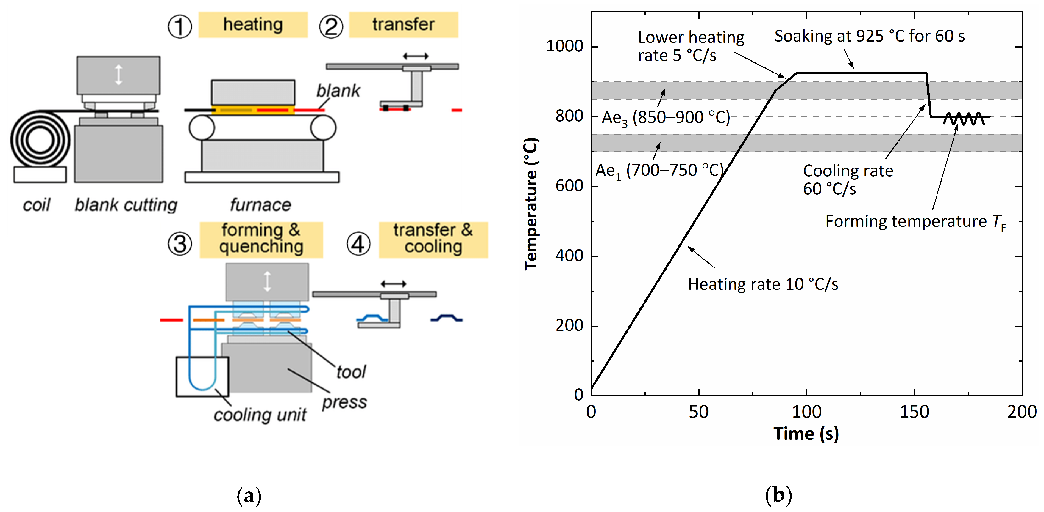
:1. Introduction
2. Uniaxial Tensile Tests for Thermomechanical Behavior Characterization
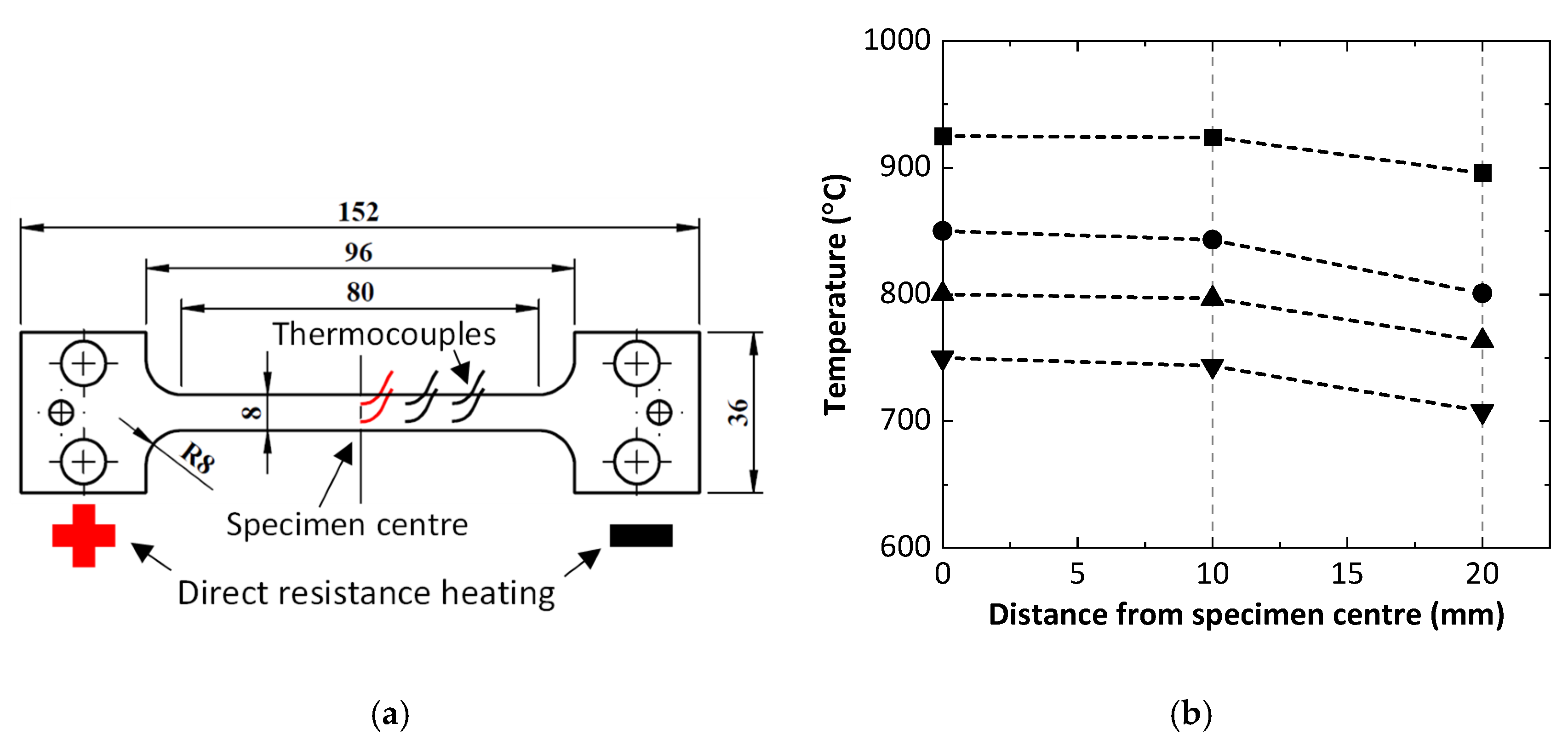
2.1. Methods of Specimen Heating and Temperature Control
2.2. Control of Strain Rates
2.3. Dependency of Stress–Strain Curves on Gauge Lengths
3. Biaxial Tensile Tests for Formability Evaluation
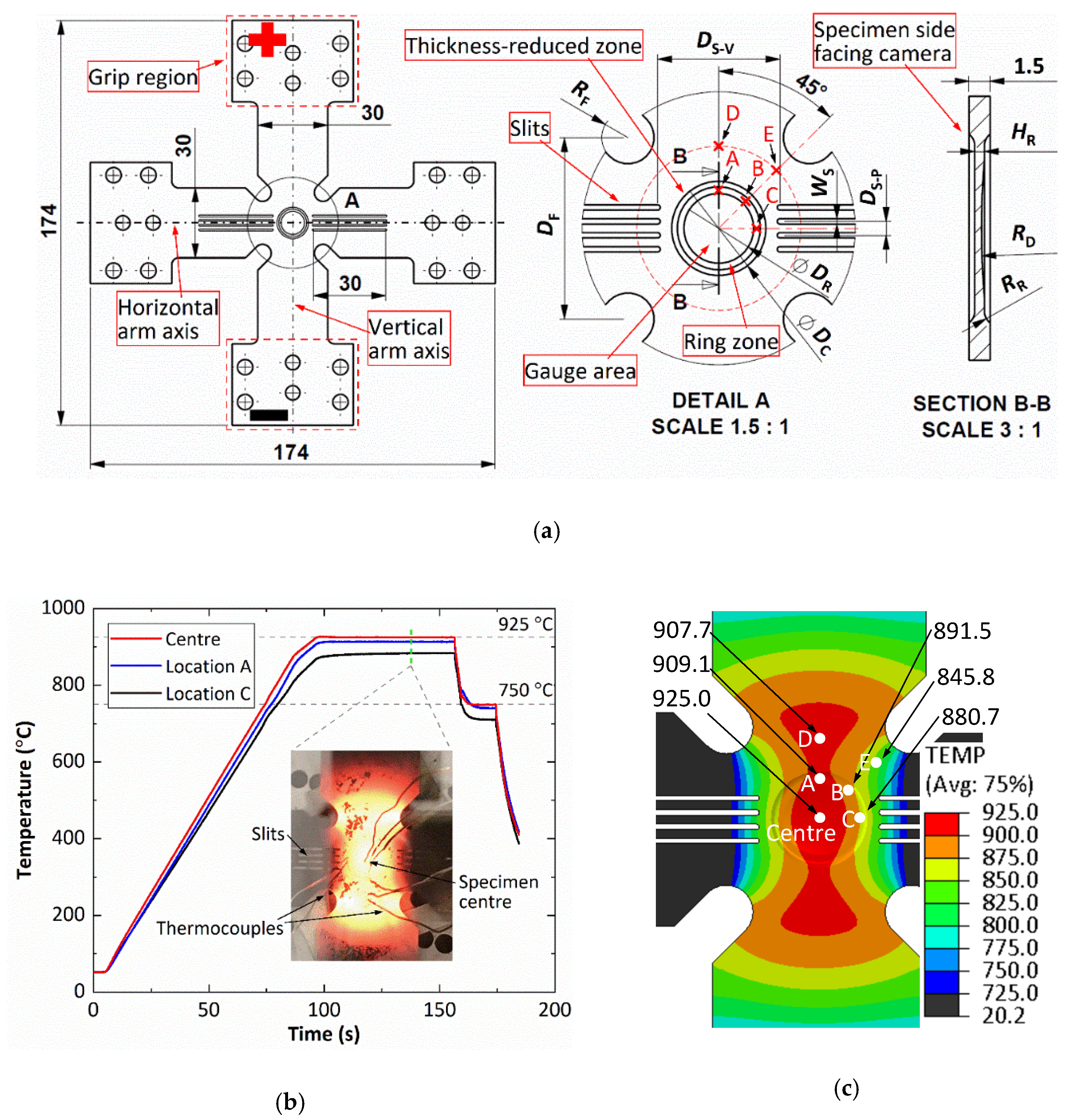
3.1. A Recent Novel Biaxial Test Method
3.2. Specimen Design, Heating Method, and Temperature Control
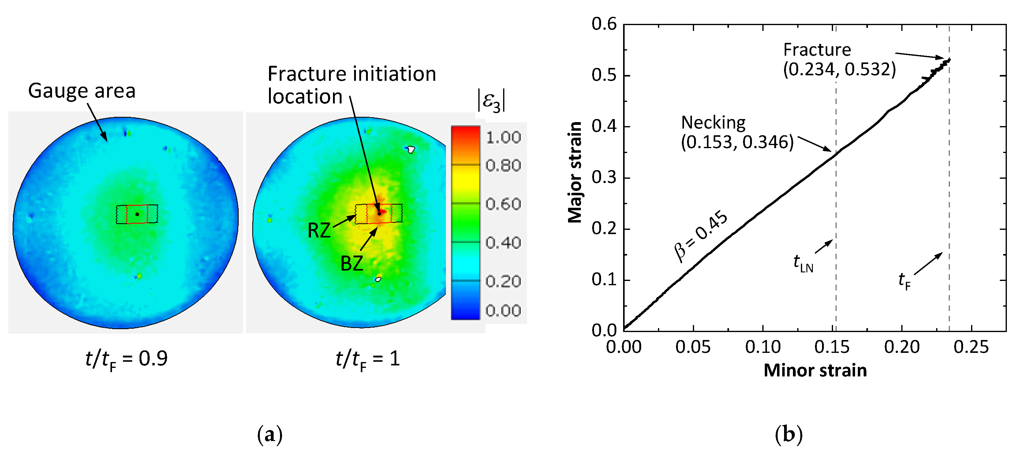
3.3. Strain Distribution in Gauge Area and Strain Path
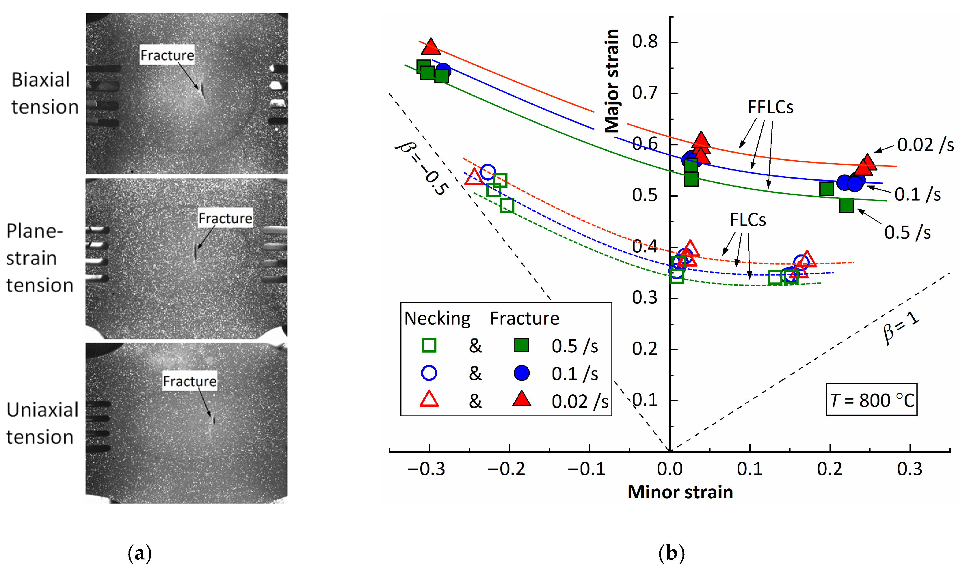
3.4. Recent Results on Thef Formability Data of Boron Steel
4. Conclusions
Author Contributions
Funding
Conflicts of Interest
References
- Zacharof, N.G.; Fontaras, G.; Ciuffo, B.; Tsiakmakis, S.; Anagnostopoulos, K.; Marotta, A.; Pavlovic, J. Review of in Use Factors Affecting the Fuel Consumption and CO2 Emissions of Passenger Cars; European Commission: Brussels, Belgium , 2016. [Google Scholar] [CrossRef]
- Manufacturing a Hardened Steel Article. GB 1490535 A, 11 December 1977.
- Lin, J.; Dean, T.A.; Garrett, R.P.; Foster, A.D. Process for Forming Metal Alloy Sheet Components. WO 2008059242 A2, 22 May 2008. [Google Scholar]
- Taylor, T.; Clough, A. Critical review of automotive hot-stamped sheet steel from an industrial perspective. Mater. Sci. and Technol. 2018, 34, 809–861. [Google Scholar] [CrossRef]
- Karbasian, H.; Tekkaya, A.E. A review on hot-stamping. J. Mater. Process. Technol. 2010, 210, 2103–2118. [Google Scholar] [CrossRef]
- Tong, C.; Rong, Q.; Yardley, V.A.; Li, X.; Luo, J.; Zhu, G.; Shi, Z. New Developments and Future Trends in Low-Temperature Hot-stamping Technologies: A Review. Metals 2020, 10, 1652. [Google Scholar] [CrossRef]
- Zhang, R.; Shi, Z.; Yardley, V.A.; Lin, J. Experimental studies of necking and fracture limits of boron steel sheet under hot-stamping conditions. J. Mater. Process. Technol. 2022, 302, 117481. [Google Scholar] [CrossRef]
- Merklein, M.; Lechler, J. Investigation of the thermo-mechanical properties of hot-stamping steels. J. Mater. Process. Technol. 2006, 177, 452–455. [Google Scholar] [CrossRef]
- Li, N.; Lin, J.; Balint, D.S.; Dean, T.A. Experimental characterisation of the effects of thermal conditions on austenite formation for hot-stamping of boron steel. J. Mater. Process. Technol. 2016, 231, 254–264. [Google Scholar] [CrossRef] [Green Version]
- Zhang, R.; Shao, Z.; Lin, J.; Dean, T.A. Measurement and analysis of heterogeneous strain fields in uniaxial tensile tests for boron steel under hot-stamping conditions. Exp. Mech. 2020, 60, 1289–1300. [Google Scholar] [CrossRef]
- Shao, Z.; Li, N.; Lin, J.; Dean, T.A. Strain measurement and error analysis in thermo-mechanical tensile tests of sheet metals for hot-stamping applications. Proc. Inst. Mech. Eng. Part C J. Mech. Eng. Sci. 2018, 232, 1994–2008. [Google Scholar] [CrossRef] [Green Version]
- Ganapathy, M.; Li, N.; Lin, J.; Abspoel, M.; Bhattacharjee, D. A novel grip design for high-accuracy thermo-mechanical tensile testing of boron steel under hot-stamping conditions. Exp. Mech. 2018, 58, 243–258. [Google Scholar] [CrossRef] [Green Version]
- Zhang, R.; Shi, Z.; Shao, Z.; Dean, T.A.; Lin, J. A novel spatio-temporal method for determining necking and fracture strains of sheet metals. Int. J. Mech. Sci. 2021, 189, 105977. [Google Scholar] [CrossRef]
- Zhang, R.; Shi, Z.; Shao, Z.; Yardley, V.A.; Lin, J. An effective method for determining necking and fracture strains of sheet metals. MethodsX 2021, 8, 101234. [Google Scholar] [CrossRef] [PubMed]
- Zhang, R.; Shao, Z.; Shi, Z.; Dean, T.A.; Lin, J. Effect of cruciform specimen design on strain paths and fracture location in equi-biaxial tension. J. Mater. Process. Technol. 2021, 289, 116932. [Google Scholar] [CrossRef]


Publisher’s Note: MDPI stays neutral with regard to jurisdictional claims in published maps and institutional affiliations. |
© 2022 by the authors. Licensee MDPI, Basel, Switzerland. This article is an open access article distributed under the terms and conditions of the Creative Commons Attribution (CC BY) license (https://creativecommons.org/licenses/by/4.0/).
Share and Cite
Zhang, R.; Lin, J. New Challenges on Developing Experimental Methods for Innovative Metal Forming Techniques. Phys. Sci. Forum 2022, 4, 15. https://doi.org/10.3390/psf2022004015
Zhang R, Lin J. New Challenges on Developing Experimental Methods for Innovative Metal Forming Techniques. Physical Sciences Forum. 2022; 4(1):15. https://doi.org/10.3390/psf2022004015
Chicago/Turabian StyleZhang, Ruiqiang, and Jianguo Lin. 2022. "New Challenges on Developing Experimental Methods for Innovative Metal Forming Techniques" Physical Sciences Forum 4, no. 1: 15. https://doi.org/10.3390/psf2022004015
APA StyleZhang, R., & Lin, J. (2022). New Challenges on Developing Experimental Methods for Innovative Metal Forming Techniques. Physical Sciences Forum, 4(1), 15. https://doi.org/10.3390/psf2022004015