1. Introduction
Integration of photovoltaic (PV) technology into vehicle technologies is an effective solution to meet energy demands and extend operational range. Some studies focus on PV-powered charging stations for electric vehicles, highlighting their environmental benefits and energy efficiency. For instance, some studies [
1,
2] examine the benefits of such systems and their impact on reducing environmental emissions. Additionally, researchers in [
3] propose an approach to optimize the location of solar-powered charging stations. While some studies consider PV systems as part of the power infrastructure for vehicles, others take a different approach by directly integrating this technology into the vehicles themselves. This integration can extend the vehicles’ operational range [
4,
5], reduce their greenhouse gas emissions [
6], and allow vehicles to utilize their full power at all speeds with minimal maintenance costs [
7,
8]. Among the various vehicular systems that leverage PV technology, unmanned aerial vehicles (UAVs) stand out due to their diverse applications, including power facility maintenance, traffic monitoring, geographic studies, surveillance, and more [
9,
10,
11]. Given the limited onboard battery capacity, integrating PV modules into UAVs offers a practical solution to extend flight endurance and reduce reliance on ground-based charging. This has led to growing interest in the design and control of UAV-integrated PV systems [
12]. Unlike ground-based or vehicle-mounted PV systems, UAV-mounted PV modules experience continuous changes in orientation due to flight dynamics [
13]. These movements affect the incident solar angle, temperature, and irradiance, which in turn influence the system’s output characteristics, especially the maximum power point (MPP), which represents the specific point on the current-voltage (I-V) curve where the product of voltage and current yields the highest power output under given conditions [
14]. Maintaining operation at the MPP is essential for optimal energy harvesting. It is typically achieved through maximum power point tracking (MPPT) algorithms [
14,
15], which adjust system parameters in real-time to follow the optimal power point. To achieve optimal performance in solar-powered vehicles, researchers have performed related studies that provide valuable insights into the integration problem of a PV module with UAVs, which shows the most complex form of movement among various vehicles. In [
16], the variation of the duty cycle is discussed to examine the impact of vehicle movement on the MPP of an integrated PV system, focusing primarily on the movement of a ship while neglecting other parameters beyond its movement.
Similarly, the authors of [
17] investigate the effects of vehicle movement on the performance of an integrated PV module through extensive field measurements. This study demonstrates how the movement of surface vehicles can significantly reduce the efficiency of conventional MPPT methods, such as perturb and observe (P&O), dropping efficiency from 95% to 55%. To study the effect of movement of the UAV, specifically on the MPPT of its integrated PV system, researchers explored various MPPT techniques. These include conventional methods like P&O and incremental conductance (IC), as well as more advanced approaches such as fuzzy logic-based control [
15]. As with any PV system, from fixed installations to those integrated into moving vehicles, MPPT control modules play an important role in UAV power management by continuously adjusting the operating point of the PV system during flight in addition to conventional methods, some studies propose simplified approaches, such as determining the MPP by regulating the output voltage of a buck-boost converter through a trial-and-error process [
18]. These approaches minimize the need for input sensors, reducing both system weight and cost. Proposed solutions in the aforementioned research are using improved versions of the conventional MPPT techniques [
13,
14,
15,
16,
17,
19,
20,
21]. Nevertheless, it is important to note that the response time of these methods has to be considered to reach MPP under fast-changing conditions.
Optimal utilization of a UAV-integrated PV system requires a comprehensive examination that goes beyond the scope of existing literature. The design and implementation must address technical demands while accounting for variables such as solar irradiation, ambient temperature, and the placement of the PV module on the UAV. Although many modeling studies focus on stationary PV systems, they fail to capture the random movements and variable orientations encountered in UAV applications, which involve six degrees of freedom. To design UAV-integrated PV systems capable of maintaining MPP under dynamic conditions, it is crucial to develop accurate models that can predict the system’s output characteristics in real time.
To achieve this, the existing modeling methods of PV modules must first be analyzed. Recently proposed PV panel modeling techniques, capable of capturing the behavior of PV modules based on their unknown parameters, can be broadly classified into analytical models [
22] and optimization-based models [
23]. Analytical modeling derives PV system parameters using the physical principles of PV cells and their governing equations, while optimization-based methods extract these parameters using objective functions and prior experimental measurements. Although these models address various scenarios, they generally assume fixed PV panels, rendering them inadequate for applications where random movements and varying operational conditions influence power output.
Given that the specifications of a PV model change with UAV’s movement and operational conditions, the current literature does not adequately address this challenge. In this context, which involves significant complexity, moving beyond conventional methods is necessary. Computational intelligence-based approaches, including metaheuristic optimization algorithms and machine learning (ML) techniques, are expected to offer effective solutions. A number of studies have applied such methods to MPPT challenges, utilizing techniques like GA-optimized artificial neural network (ANN) MPPT [
24], fuzzy logic and ANN MPPT [
25], particle swarm optimization (PSO)-based MPPT [
26], and reinforcement learning algorithm-based MPPT [
27]. Additionally, some research has employed ML approaches to model fixed PV systems under varying environmental conditions, demonstrating their capability to manage system complexities efficiently [
28,
29].
To overcome the gap of the current body of research, this paper proposes, to the best of our knowledge, for the first time in the literature, a ML-based model to cope with the UAV-integrated PV module dynamic and continuous movement, and the high burden of calculations. To achieve the stated goal, the study defines the following objectives:
Develop a machine learning framework capable of accurately forecasting the maximum power point under diverse UAV flight conditions and movement patterns.
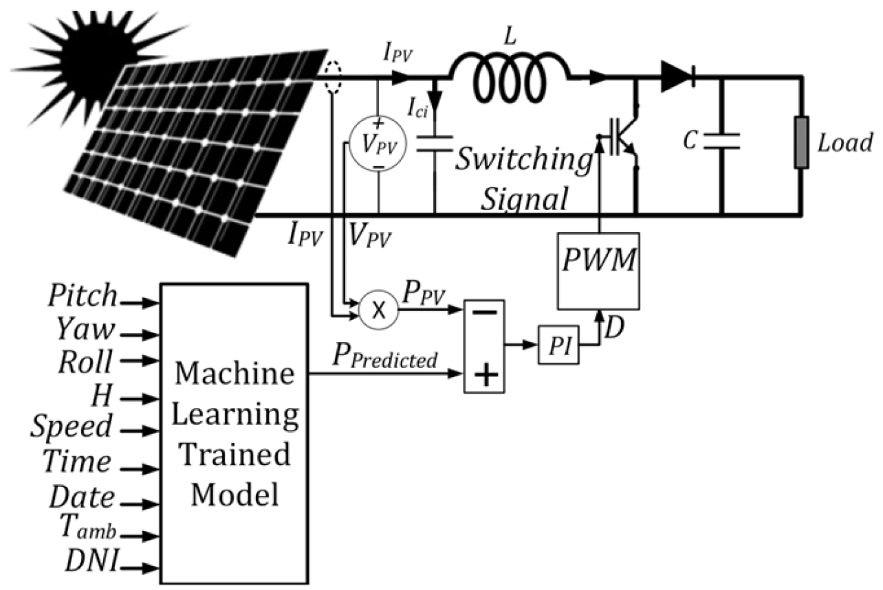
Design a hybrid MPPT controller that integrates predictive modeling with real-time optimization for enhanced tracking performance.
Validate the proposed system through comprehensive simulation and hardware experiments to demonstrate its effectiveness in real-world scenarios.
To this aim, first, a one-year environmental historical dataset gathered for the Canadian capital region [
30] is processed through the PV module empirical driven equations (EDE) in combination with the grey wolf optimization algorithm (GWO) to obtain a target MPP dataset related to a flying UAV. GWO is used for adaptively finding the PV module diode ideality factor for different conditions of its placement, and its superiority is assessed compared to PSO. The aforementioned dataset is used to train ML models to predict the MPP parameters of a commercial ET-M53695 PV panel. Then, the performance of the developed ML models is evaluated based on test error metrics. Moreover, a hybrid ML-based MPPT technique is employed based on the trained model. Finally, experimental measurements and hardware experimental tests implemented by dSPACE MicrolabBox are presented to validate the performance of the trained model. The proposed approach can be used in the MPP control and design of PV panels integrated into UAVs. The main contributions of the paper are as follows.
A novel approach is employed to translate the complex movements of the UAV-integrated PV module into fundamental operational angles of the PV module.
A new solution based on GWO is proposed to compute the PV module diode ideality factor for different placement conditions of the PV module.
A series of ML algorithms, which predict the MPP parameters of the UAV-integrated PV panel based on the environmental and placement conditions of the UAV, are validated to provide a prediction of the PV panel output in every instance of UAV flight.
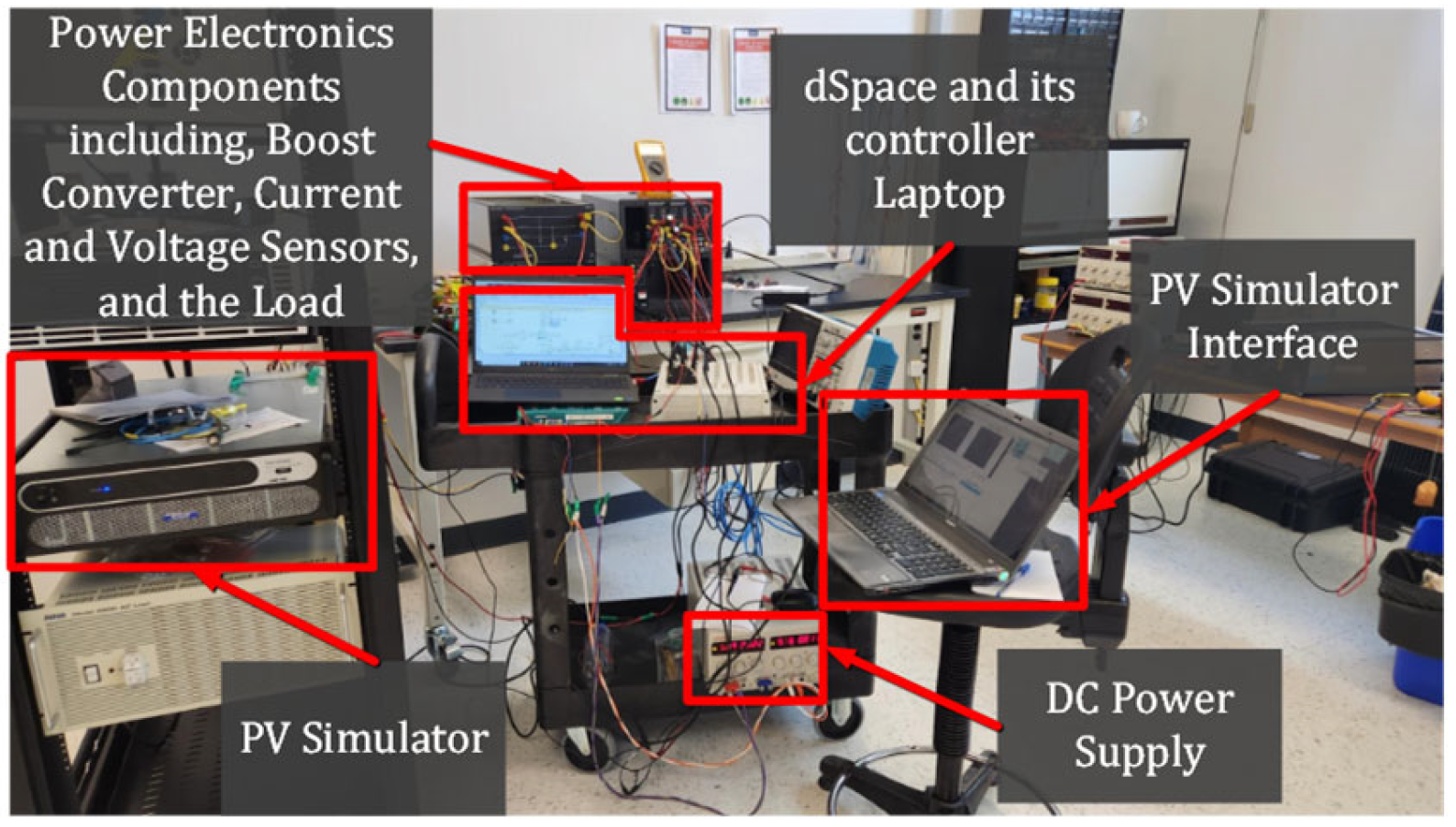
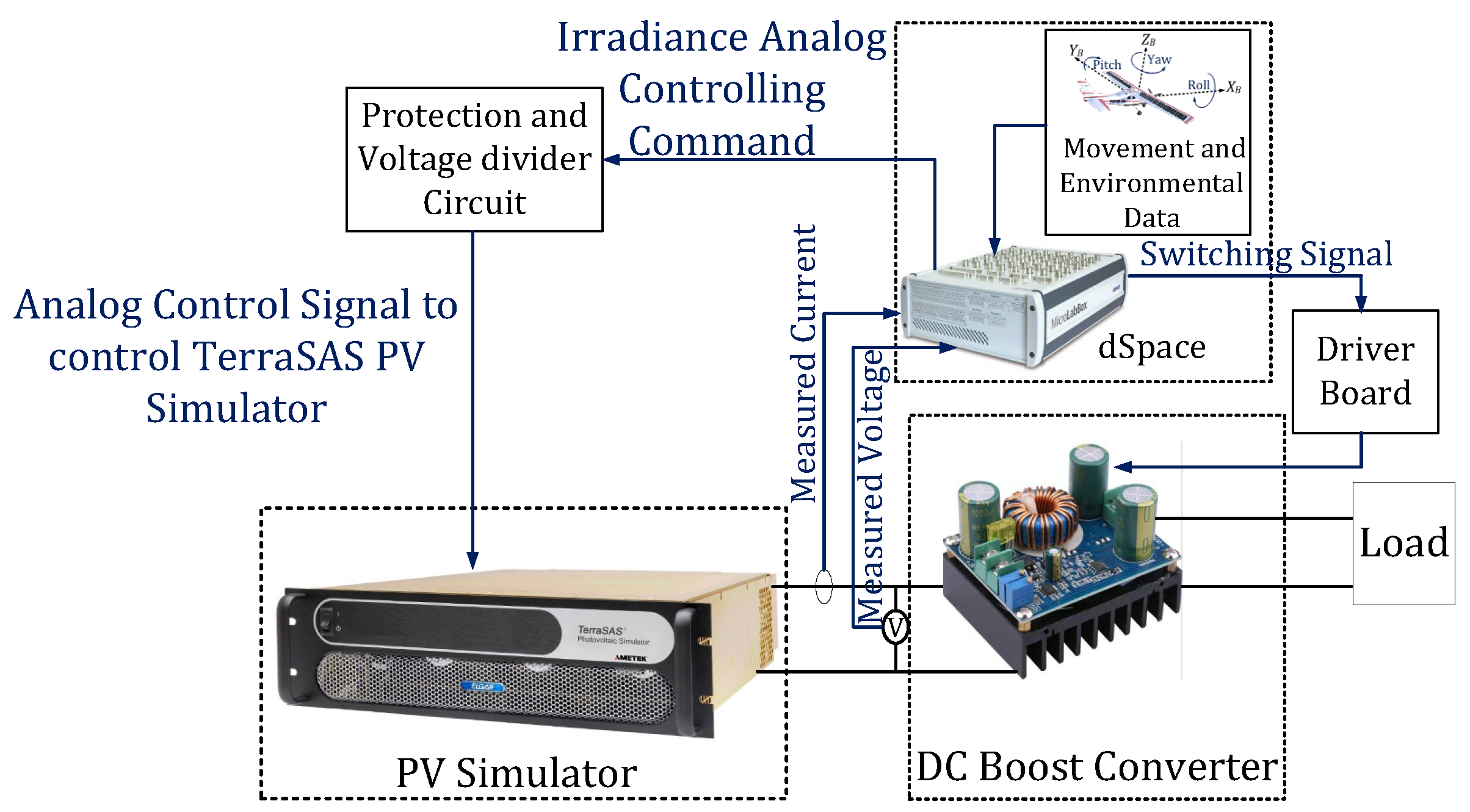
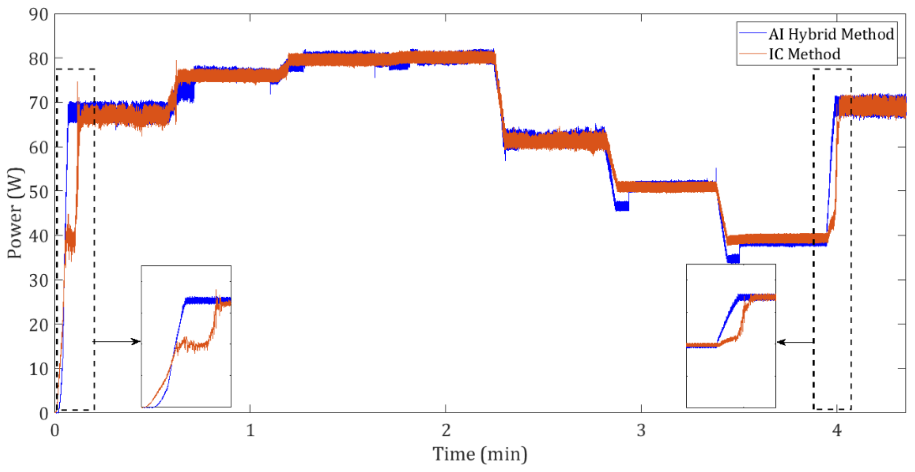
A hybrid MPPT technique using the integration of the proposed ML-based model with an IC MPPT is implemented experimentally.
This paper is organized as follows:
Section 2 presents the methodology, including the mathematical modeling of UAV movement and its impact on PV module orientation, as well as the adaptive calculation of the diode ideality factor using GWO.
Section 3 details the development of the machine learning-based MPP prediction model, including dataset preparation, model training, and computational cost analysis.
Section 4 discusses the results, including model performance, experimental validation, and hardware implementation of the hybrid MPPT controller. And finally,
Section 5 concludes the paper by summarizing the key contributions and outlining potential future work.
2. Methodology
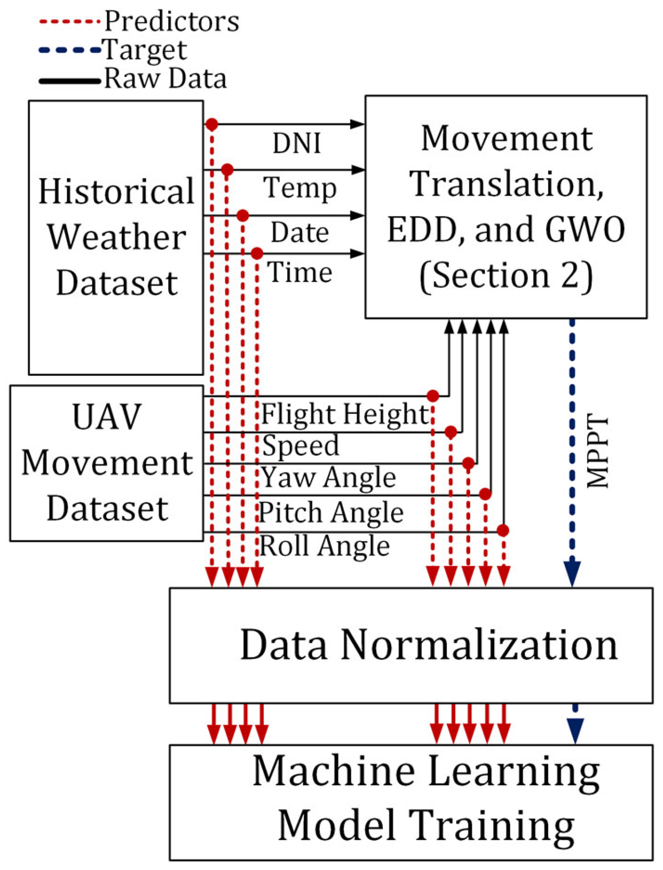
The dynamic nature of a UAV’s flight, characterized by continuous change in altitude, orientation, speed, and temperature, introduces significant variability in the PV system’s parameters for each movement and meteorological condition. These fluctuations lead to a considerable challenge in maintaining the PV panel at its MPP. To address this limitation, the proposed method integrates analytical analysis, metaheuristic optimization, and ML approaches. As illustrated in
Figure 1, the process begins with the collection of a one-year historical meteorological dataset [
16], which includes irradiance, temperature, and time-based parameters. This is combined with a synthetically generated dataset representing UAV flight properties, such as altitude, speed, and orientation angles (roll, pitch, yaw), within realistic operational ranges. These combined datasets are then processed using a new proposed approach to translate the movement of UAV to the basic placement parameters of the PV module [
31], and using EDE in conjunction with the metaheuristic optimization methods, including GWO and PSO, to generate the final dataset suitable for training ML models. Finally, 23 ML-based models are trained to predict the MPP properties of the UAV-integrated PV module, enabling efficient control of the PV panel’s performance under varying UAV movements and meteorological conditions. This number of models is trained to ensure that the best available ML model is selected for the available dataset. The schematic representation of this approach is illustrated in
Figure 1.
The final output of the proposed method is a predictive model capable of estimating the initial operating point of the PV module, either precisely at or near the MPP, based on nine input features: solar irradiance, ambient temperature, date, time, UAV speed, altitude, roll, pitch, and yaw. This prediction significantly reduces the computational burden on the UAV’s controller and enhances real-time MPPT responsiveness.
2.1. PV Module Angles in Terms of UAV Rotation
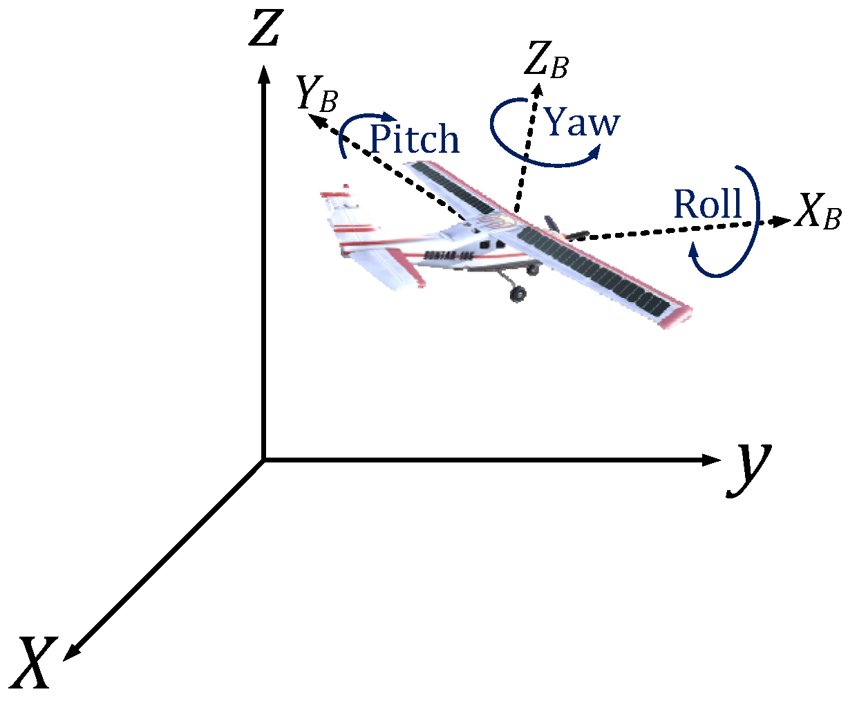
To identify the precise relationship between UAV movements and PV module tilt and azimuth angles when rotations occur simultaneously around all UAV axes, an in-depth mathematical analysis of their interdependence is required. To analyze the rotational movements of the UAV, the relation between the world frame and the UAV body frame must be explored. These two frames for a random condition of the UAV flight are shown in
Figure 2 as well.
The UAV’s roll, pitch, and yaw movements alter the body frame’s orientation relative to the fixed frame. Rotational matrices, here the Tait–Bryan rotation matrix, establish the trigonometric relationships needed to compute the new body frame [
32]:
where
θ,
ϕ, and
ψ are roll, pitch, and yaw angles of the UAV’s body, respectively. In order to achieve a rotated frame, the following relation between the world and body frame is established.
where
xb,
yb, and
zb represent the coordinates in the body frame, while
x,
y, and
z denote the coordinates in the fixed frame.
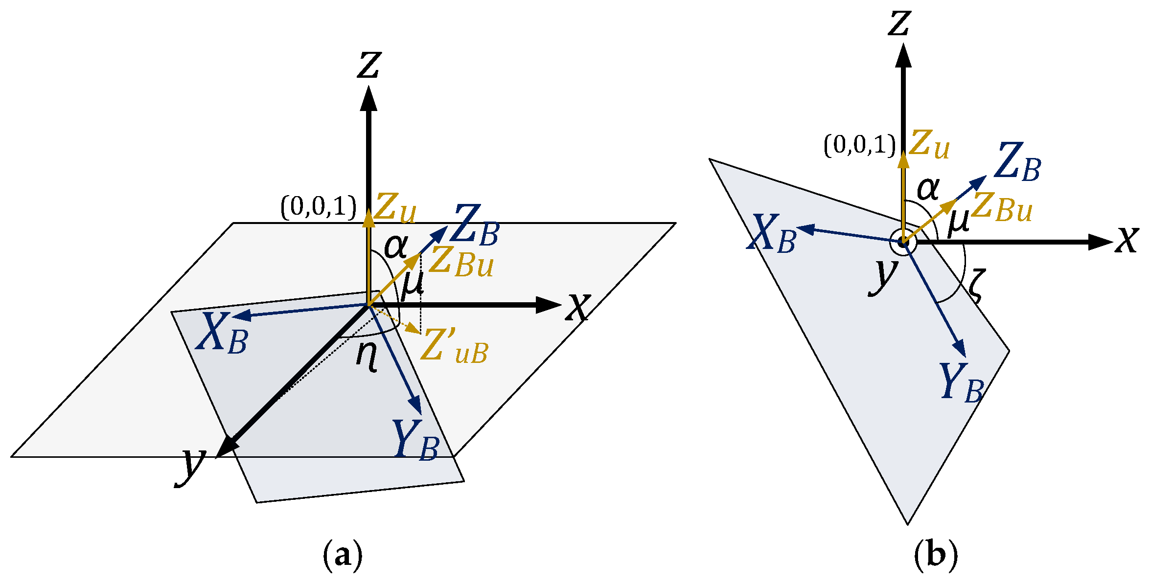
In aerospace dynamics, rotation matrices are commonly used to transform vectors between coordinate frames. For this study, the body frame refers to the UAV’s local coordinate system, while the world frame (or fixed frame) represents the Earth’s reference system. The orientation of the PV module is affected by the UAV’s roll, pitch, and yaw, which are captured through rotation matrices that transform the body frame vectors into the world frame. The Z-axis of the body frame, along with its corresponding unit vector (
ZBu) maintains orthogonality with respect to the UAV-integrated PV module, as illustrated in
Figure 3. Since the tilt angle of the PV panel represents the number of degrees from the horizontal plane, this angle can be determined by measuring the degrees between
ZBu and the horizontal plane. In order to find the mentioned angle, first, the angle between
ZBu and
Zu has to be investigated. Since the location of the UAV does not affect this angle, it can be determined by considering the two frames as concentric.
Figure 3a,b depict the X-Y plane within the body and world frames and the associated angles from two different perspectives. In these figures, α is the angle formed between
ZBu and
Zu,
μ is the angle that
ZBu forms with the world frame X-Y plane, and
ZBu′ is the projection of
ZBu on the world frame X-Y plane. To calculate the angle between
ZBu and
Zu, the dot product formula and trigonometric functions can be used. Based on the earlier discussion about rotation matrices and their application,
ZBu can be derived in the fixed frame coordination by applying the rotation equations to
Zu. With
Zu and
ZBu available, the α can be derived as follows:
Figure 3 illustrates that α and
μ form two complementary angles, while ζ and
μ also constitute two complementary angles. It is evident that ζ and α represent the same angles, and ζ is obtained through the calculation of α. ζ represents the angle at which the body frame X-Y plane is formed with the world frame X-Y plane and is indicative of the PV panel’s tilt angle. Furthermore, the azimuth angle of the PV panel can be determined by the angle formed between
ZBu′ and the world frame’s Y axis, which is shown by
η. It can be calculated as follows:
where
and
are the X and Y coordinates of the
ZBu in the world frame X-Y plane. The angles presented in this section enable the inclusion of UAV movement around its various axes in the PV module equations that are used in the upcoming sections.
2.2. PV Module Mathematical Governing Equations
Following the interpretation of UAV movement in terms of PV module angles in the preceding section, it is now possible to incorporate UAV movements into the analysis of its integrated PV module output power. In line with the power analysis, it becomes crucial to adaptively determine the diode ideality factor of the PV module in relation to each UAV movement. All of these concepts are elaborated upon in this section.
Maximum Power Point Calculations
In most instances, existing literature primarily employs the analysis of PV modules based on the PV module equivalent circuit models, notably the single diode model [
22]. However, the EDE analysis utilized in this paper is proposed by [
33], which has been derived and validated empirically.
To find the MPP voltage and current of the PV module, the following equations are proposed [
33].
where the numerical parameters, including
Kvm,
KIm, and C
0–C
3, can be extracted from the manufacturers’ datasheets or the modules’ available databases. In addition,
is the thermal voltage of PV module, as
Tc is the P-N junction temperature in Kelvin,
q = 1.60217646 × 10
−23 C is the charge of the electron,
K is the Boltzmann constant which is equal to 1.3806503 × 10
−23 J/K, and
Ns is the number of solar cells connected in series. STC subscription denoted the standard test condition (STC), representing cell temperature of 25 °C, irradiance of 1000 W/m
2, and air mass (AM) of 1.5. Moreover,
Geff is the effective irradiance ratio and is calculated based on the following equation:
where
Ksf accounts for factors related to module aging,
G is the effective irradiance incident on the PV module surface,
Gstc is the irradiance at the STC condition, and
f(
AM) and
f(
AOI) determine the impact of changes in the solar spectral distribution and optical losses. In (8), three computable parameters must be determined in order to calculate the value of
Geff.
The available solar radiation (
G) that a PV module can harvest is known as the plane of array (POA) irradiance. It is a combination of the direct radiation that travels straight through the air to the PV module surface (
Gdir), of the scattered sunlight caused by molecules and tiny particles in the air, which is known as diffused radiation (
Gdif), and of the light that bounces off the ground or nearby surfaces and then reaches the PV surface, which is known as reflected radiation (
Gref). Since the current study is performed for an UAV application, the latter component can be neglected. Therefore, the amount of available irradiance is computed as:
Direct beam radiation (
Gdir) is given by [
34]:
where direct normal irradiance (
DNI) is direct normal irradiance, and AOI is basically the angle between the direct sun ray and a line perpendicular to the surface of the PV module. It can be calculated as follows:
where
β and
A are the altitude and azimuth angles of the sun,
φ is the PV panel azimuth angle, and
θT is the PV panel tilt angle. The altitude angle and azimuth angle of the sun are shown in
Figure 4 and are computed as:
where
L is the latitude of the flying UAV,
is the hour angle as
ST is the solar time [
22], and
δ is the angle between the imaginary line passing through the center of the sun and the center of the earth, and the polar axis is changing over a year. As shown in
Figure 5, this angle changes between −23.45° in winter and +23.45° in summer and can be estimated by the following sinusoidal equation [
34]:
where
n represents the day number in a year.
The diffused radiation component of the solar irradiance can be calculated as follows [
34]:
where
C is a sky diffuse factor and is calculated as:
The two other unknown parameters in (8), namely
f(AM) and
f(AOI), are given by [
33]:
where
a0–
a5 and
b0–
b5 can be accessed through different module specifications, which are prepared by the National Renewable Energy Laboratory (NREL) [
35], and
AM is the air mass, which is the amount of air within the atmosphere that the sun’s rays pass to strike the PV panel. The value of AM can be calculated by:
where
r is the ratio of the Earth’s radius to the thickness of the atmosphere and is approximately 708.
Incorporating the impact of UAV speed on the integrated PV module’s performance involves calculating the module’s temperature in relation to the UAV speed, and this calculation can be carried out as described in [
36]:
where
d = −3.58 and
b = −0.113 are the constants that depend on the module material and construction,
Tamb is the ambient temperature, and
Speed is the UAV speed in m/s.
Another parameter that is still unknown in (6) is
a, which is the ideality factor of the PV module diode. In general, the value of this parameter is between one and two and in numerous studies, such as [
37], for example, it is considered a constant parameter. But in a real application, the amount of ideality factor is changed for various module temperatures and irradiances. Extracting this parameter for a specified condition of implementation is challenging enough and is usually done by using repetitive methods, considering the derivation of the calculated
Pmpp and the measured
Pmpp as its condition of convergence. In this work, a new approach is used based on GWO to extract the ideality factor of the UAV-integrated PV module.
2.3. Adaptive Calculation of Diode Ideality Factor
GWO, a metaheuristic inspired by grey wolf behavior, has advantages like fewer parameters, simplicity, and easy implementation over methods like PSO and GA [
38,
39]. In this optimization method, wolves are categorized as alpha, beta, delta, and omega based on their performance. Alphas lead and make decisions for the pack, betas act as alternatives, deltas hold a hierarchical position, and omegas follow orders. In the optimization problem, alpha, beta, and delta wolves represent the optimal, second optimal, and third optimal individuals, respectively.
Grey wolves hunt their prey through three main steps, including (1) pursuit, tracking, and approaching the prey, (2) chasing, encircling, and harassing the prey until it stops, and (3) attacking the prey [
38].
Mathematical modeling of prey encirclement includes considering the distance between the prey and the wolves (
D) using the following formula [
38]:
where
t indicates the iteration number,
denotes the position vector of the prey,
X is the position of a grey wolf, and
and
stand for coefficient vectors and can be calculated as follows [
38]:
where
and
are two random vectors between 0 and 1, and components of
linearly decrease from 2 to 0 as the iterations progress.
According to the wolves’ behavior, the idea is that these three types of wolves have the best knowledge about the possible location of the prey. So, only the three best solutions are considered, while their position updating can be considered as follows [
38]:
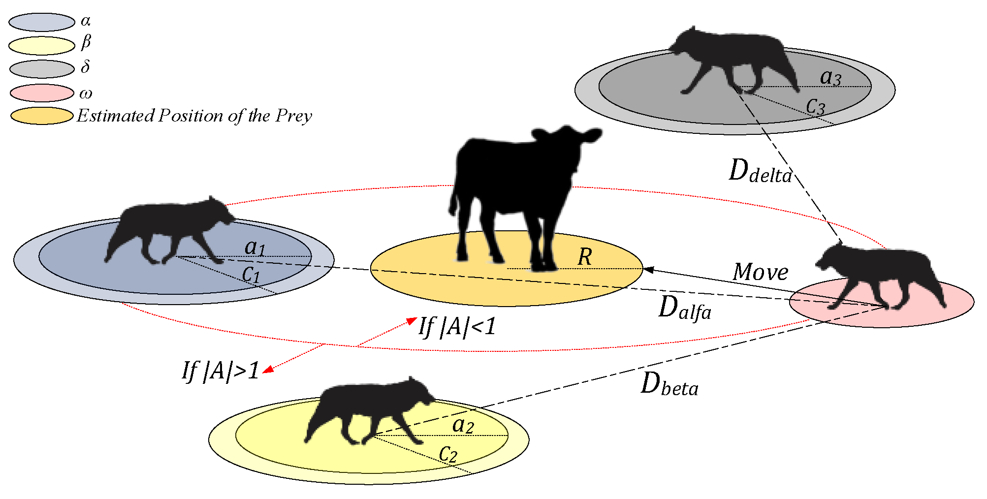
Using the equations provided above, the wolves adjust their positions relative to the prey. The algorithm iteratively operates until the specified stopping condition is met, which involves the search agents (wolves) reaching the objective function (prey). This process involves updating the position of omega wolves based on the movements of the other three main wolves that are exploring the search environment and are closest to the prey. This behavior is exhibited by omega wolves during the exploration phase and is determined by parameter A. Essentially, the next position of a search agent can be anywhere between its current position and the prey. When |A| is less than 1, the search agent is directed to approach the prey, while |A| greater than 1 leads the search agent to adjust its position in response to the movements of the three best-performing wolves. These concepts regarding the updating position procedure, as well as the hunting or searching behavior for a prey, are illustrated in
Figure 6. In this study, the objective of the GWO is to minimize the disparity between two sets of
Vmpp equations by tuning the value of the PV module ideality factor (
a). The first set was discussed in the previous subsection, while the second set is validated by [
40] and is calculated as follows:
The explained objective function can be formulated as follows:
In the implementation of GWO in MATLAB 2024a, the number of search agents was set to 10, and the maximum number of iterations was set to 10. These values were selected based on preliminary tuning experiments to ensure a balance between convergence reliability and computational efficiency. Given the real-time constraints of the UAV-integrated PV system, a compact population and limited iteration count were preferred to reduce processing time while maintaining acceptable optimization accuracy. The bound range for the ideality factor (1 to 1.25) was adopted from experimental tests reported in [
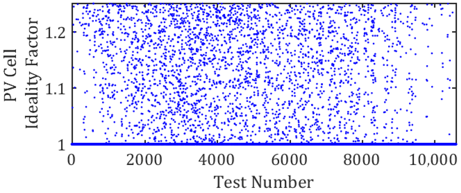
41], ensuring that the search space remained physically meaningful and consistent with observed data. The extracted ideality factors for different movements of the UAV are illustrated in
Figure 7. To assess the performance of the GWO algorithm in extracting the depicted ideality factor and compare it with other metaheuristic algorithms, including PSO and moth flame optimization (MFO), the convergence curves are presented in
Figure 8. These curves reveal that in each execution of the GWO, the algorithm consistently reduces the value of the objective function by adjusting the parameter
a. Moreover, one can notice that GWO converges to the objective function faster than the other two algorithms. Moreover, PSO and MFO yielded an average best score (convergence error) that was 3% and 1.5% higher than that of GWO, respectively, demonstrating GWO’s superior optimization performance. This demonstrates GWO’s ability to achieve more precise ideality factor extraction. In most cases of algorithm runs, the objective function remains unchanged after the second iteration due to the limited range of
a. 3. Computational Intelligence MPP Model
3.1. Dataset Preparation
The ML development related to the UAV-integrated PV module is carried out based on the one-year historical environmental dataset of the Canadian capital region, which is accessible through the NREL website [
35]. The dataset includes one-year data associated with the ambient temperature (°C), DNI (W/m
2), and the time and date of data collection. This dataset provides high-resolution solar and meteorological data, which served as the foundation for the performed analysis.
Additionally, the height of the flight, the operational angles of the plane, and their operating speed are generated randomly in acceptable ranges. Following the classifications provided by the North Atlantic Treaty Organization (NATO) and the National American Space Agency (NASA) as documented in [
42,
43], the maximum flight altitude for Class I aerial vehicles, characterized as small flying vehicles (weighing under 150 kg), is set at a threshold of 6000 m. Additionally, the speed of the UAVs within Class I falls within the range encompassing their stall and top speeds, as defined by various models within this class according to [
44]. This speed range is selected to be between 100 km/h and 200 km/h.
Moreover, the pitch and roll angles, which are known as the angle of attack and bank angle, respectively, are considered −30 to 30 and between −30 to 30, respectively, which is a reliable range based on [
43]. Moreover, the acceptable value of the yaw angle is considered between 0 and 360 degrees in order to cover the whole space of possible flight directions. The temperature of the PV panel in the UAV’s flight height decreases by 6.5 °C for every 1000 m increase in the flying height [
45].
Prior to model training, the raw data underwent a series of preprocessing steps, where the two most important ones are mentioned in the following sections. First, the raw data is processed and cleaned to remove missing or anomalous entries that could compromise model accuracy. Then, to ensure uniformity across features and facilitate convergence during training, all input variables were normalized using min-max scaling. And finally, the prepared dataset is utilized for model training.
3.2. Final Dataset Preparation
In order to achieve the final dataset, the raw data are processed with the method proposed in earlier sections. Based on the explained concepts in
Section 2 and
Section 3, important parameters of a UAV-integrated PV system, including the diode ideality factor and the MPP point parameters, are computed for any available UAV movement and environmental condition. In this study, the MPP power is selected as the ML target feature. The aforementioned parameter is extracted for the ET-M53695 commercial PV module. The resulting dataset, obtained after removing data points that lack logical or meaningful information, such as instances when there is no irradiance or when module placement results in absorbed irradiance falling below 100 W/m
2 (a threshold at which the module ceases power generation) [
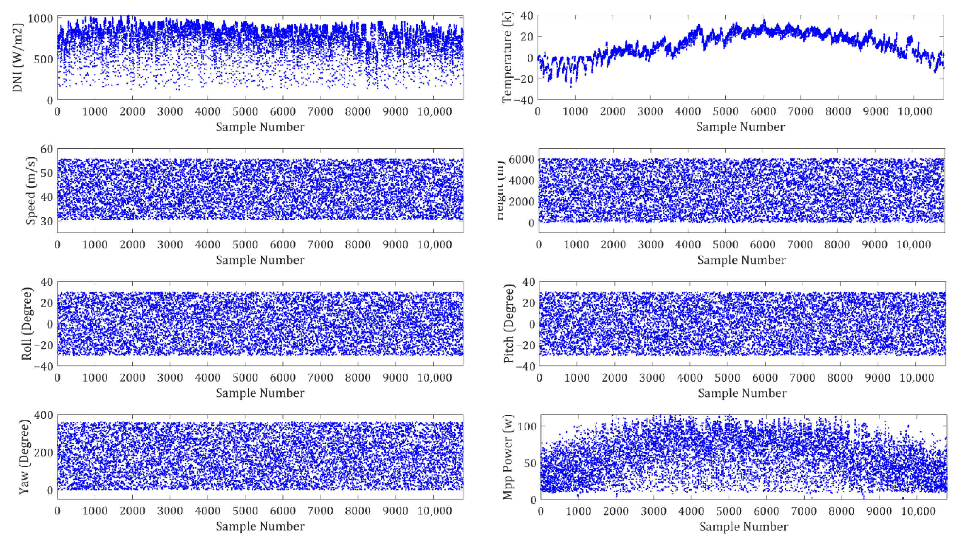
46], consists of 10,656 data points. The scatter plots of the dataset predictors and target features are shown in
Figure 9. These features include DNI, Speed, Roll angle, Pitch angle, Azimuth angle, Height of flight, and Temperature. The target variable is the power of MPP. Date and time are excluded from the scatter plots.
3.3. Data Normalization
Data normalization is an important step in data preprocessing. The goal of data normalization is to scale all the parameters to a common range without distorting the data points’ differences. The data is normalized between 0 and 1 according to the following equation:
where
xnorm,
xmin,
xmax, and
xi are the normalized value of the sample, the minimum amount of observation in the dataset, the maximum amount in the dataset, and the current datapoint, which is normalized, respectively.
3.4. Machine Learning Models Training
In order to find the best possible ML model describing the system’s performance in the most efficient way, various ML models are trained and evaluated for the previously mentioned PV module type. To perform validation on training, a 10-fold cross-validation is utilized; also, 20% is set aside as the test set. In total, twenty-three models using six different techniques, including Gaussian process regression (GPR), linear regression (LR), support vector machine (SVM), ensemble regression trees (ERT), and artificial neural networks (ANN), are trained and evaluated.
For stepwise linear regression, the maximum number of steps is set to 1000. The kernel scale for fine Gaussian SVM, medium Gaussian SVM and coarse Gaussian SVM is set to 0.75, 3, and 12, respectively. In addition, the number of iterations for all neural network models is 1000, and the activation is set to ReLU. The first layer size is set to 10, 25, and 100 for narrow, medium, and wide neural networks, respectively. Moreover, the size of the first and second layers is set to 10 for both the bi-layered and tri-layered models, and the third layer size for the tri-layered model has been set to 10 as well.
3.5. Computational Cost of the Proposed MPP Model
All processes in this research were executed on a Dell Optiplex 9020 desktop equipped with an Intel Core i7-4790 CPU (3.6 GHz), Intel HD Graphics 4600, and 8 GB DDR3 RAM. The computational cost primarily lies in the training phase of the machine learning models and the optimization processes using GWO and data normalization.
The training phase, which involves processing historical environmental and flight data, training ML models, and validating their performance, was performed on the same hardware and took approximately 1 h.
Moreover, the inference time, which is the time the trained models take to predict the unknown parameter, is in the range of hundreds of microseconds. This rapid inference time ensures that the model can provide real-time predictions during UAV flight operations.
5. Future Work
While the proposed hybrid MPPT approach has demonstrated strong performance in both simulation and hardware implementation, several avenues remain for future exploration. One promising direction is the extension of the model to accommodate other PV technologies, which may exhibit different electrical characteristics and environmental sensitivities. Additionally, incorporating further environmental variables, such as wind speed, humidity, and atmospheric pressure, could enhance the model’s predictive accuracy and robustness under dynamic operating conditions.
Long-term field testing across diverse geographic and climatic zones would also be valuable in validating the system’s generalizability. Although the current dataset originates from the Canadian capital region, the framework itself was designed to be geographically agnostic, leveraging a wide range of input parameters, including solar irradiance, temperature, UAV flight altitude, rotation angles, speed, day, and time. This adaptability suggests strong potential for deployment in varied environments.
Finally, future work may explore deeper integration of the machine learning model with other MPPT techniques to create hybrid controllers that balance precision, responsiveness, and computational efficiency, particularly for real-time applications on resource-constrained UAV platforms.
6. Conclusions
This study presents a comprehensive computational intelligence-based method for modeling and optimizing UAV-integrated photovoltaic (PV) systems under dynamic flight conditions. A novel mathematical approach was developed to translate UAV movement, specifically roll, pitch, and yaw, into the tilt and azimuth angles of the PV module, enabling accurate orientation modeling. Furthermore, a novel method utilizing the EDE of the PV module and the GWO algorithm simultaneously is developed to adaptively calculate the diode ideality factor, outperforming PSO with a 3% lower convergence error. After processing a dataset of 10,656 data points through the EDE of the PV module to determine the MPP current and voltage properties and adaptively derive the diode ideality factor, twenty-three ML models were developed for the ET-M53695 commercial PV panel. A 10-fold cross-validation method is used for model validation, and 20% of the dataset was utilized for the model testing process. Among the various trained ML models, the RQGPR model demonstrated the best performance, achieving an RMSE of 0.006. To validate the proposed approach, a series of experimental tests was conducted on a PV module using an IV-400 photovoltaic analyzer attached to a mobile mechanism capable of simulating UAV movements by rotating around its yaw, pitch, and roll axes. The predictions made by the RQGPR-trained model under the experimental conditions closely matched the actual measurements. Moreover, to show the capability of an ML-trained model in a power electronics context, a hybrid MPPT method combining AI-based techniques with traditional IC methods was implemented, showing improved performance in tracking the MPP during high variation irradiance changes. Experimental validation confirmed the model’s effectiveness in predicting MPP under various UAV movement scenarios, and a hybrid MPPT controller integrating the ML model with IC was successfully implemented in hardware. These results underscore the practical viability of the proposed approach.
