1. Introduction
Concentrated photovoltaic (CPV) technology uses small solar cells to produce the same amount of electrical energy as a flat-plate photovoltaic panel while using a fraction of the semiconductor material—typically 500 times less. This is achieved by replacing the semiconductor material with optical components that concentrate solar radiation onto the cell, increasing its maximum power output. For comparison, the efficiency of a 4 cm
2 monocrystalline silicon cell is 26.6%, while that of a multijunction cell without concentration is 38%. For GaInP/GaInAs and GaInAsP/GaInAs multijunction cells under 655 suns, efficiency reaches 47.6% [
1]. Higher efficiencies are achieved at greater concentration levels, sometimes exceeding 1000 suns. Ferrer-Rodríguez et al. (2020) [
2] characterized a photovoltaic cell array under concentrations exceeding 6000 suns. However, while efficiency increases with concentration, this relationship is not linear and depends on efficient heat removal and a uniform radiative flux distribution, as high-intensity levels concentrated on a single point of the cell can reduce efficiency or cause irreversible damage.
Various strategies to achieve radiative flux distribution in solar concentration systems, for diverse applications, have been reported in the literature. Winston et al. 2011 [
3] propose adding optical elements, such as aspheres, to enable the redistribution of radiative flux. Ling et al. (2018) [
4] propose a passive strategy to enhance the receiver’s capacity to transfer concentrated solar radiation (CSR) to the heat transfer fluid (HTF). Meanwhile, Yu Q. et al. (2024) [
5] suggest dividing the concentrating mirror of a solar furnace into four quadrants, to be used for operating thermochemical reactors. This approach aims to achieve a homogeneous flux distribution through disorientation and reflection crossing. However, the reported study is theoretical and considers ideal operating conditions.
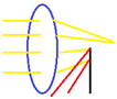
Another strategy to achieve uniform flux distribution across the cell area or densely packed photovoltaic arrays, commonly used on point-focus concentration systems, involves light pipes or homogenizers. Square truncated-pyramid homogenizers, such as the one shown in
Figure 1b, have been proposed and studied since 1962 for conditioning solar radiation concentrated by solar furnaces and electric arc furnaces [
6]. These are designed to reduce thermal stress in the central zone of a material exposed to high concentration levels. For such applications, this issue can be addressed by moving the material out of the focal zone. However, in photovoltaic concentration applications, radiative flux distribution, while less intense at the center, would still lack uniformity across the cell area. Additionally, it is worth noting that concentrator defects become more apparent off-focus. Depending on the application, this effect may be undesirable and negatively impact the system’s optical efficiency.
The general principles of homogenizer operation are described in detail by Chen et al. (1963) [
7]. The process involves collecting concentrated radiative energy at the focal plane of the concentrator and introducing it into a waveguide or light pipe. This waveguide is typically a prism with reflective inner walls, where the entrance area can have a constant geometry or vary proportionally (e.g., a truncated pyramid). The uniformity of the radiative flux distribution improves with an increase in the device’s length. However, extending the homogenizer beyond what is necessary is not advisable, as absorption losses increase with the length of the device due to multiple reflections.
Shanmugam et al. (2023) [
8] designed a CPC-CPVT system that achieves a certain degree of uniformity, although their proposal is focused on low-concentration systems. In contrast, Vu et al. (2024) [
9] present a theoretical study on the design of a homogenizer inspired by the eye of a crustacean. This aims to homogenize the radiative flux in a CPV system using a parabolic dish mirror, reporting a uniformity level close to 85% under ideal operating conditions.
Conversely, some authors [
10,
11] designed and constructed hollow homogenizers with a constant cross-sectional area for solar furnaces. These studies report operation issues and low uniformity levels, highlighting the need for theoretical studies prior to the manufacturing process.
This article presents the optimization of a radiative flux homogenizer prototype to adjust the radiative flux distribution in a solar furnace. The goal is to characterize an array of densely packed triple-junction concentrator photovoltaic cells subjected to high-concentration radiative fluxes.
The authors deem it important to clarify that the prototypes presented in this article are intended solely for research purposes. Specifically, they have been designed as laboratory equipment aimed at the characterization and evaluation of multijunction photovoltaic cells, rather than for large-scale production or electricity production. Like other re-search instruments, these prototypes are typically expensive and undergo iterative rede-sign processes to optimize their performance.
2. Radiative Flux Homogenizer Optimization
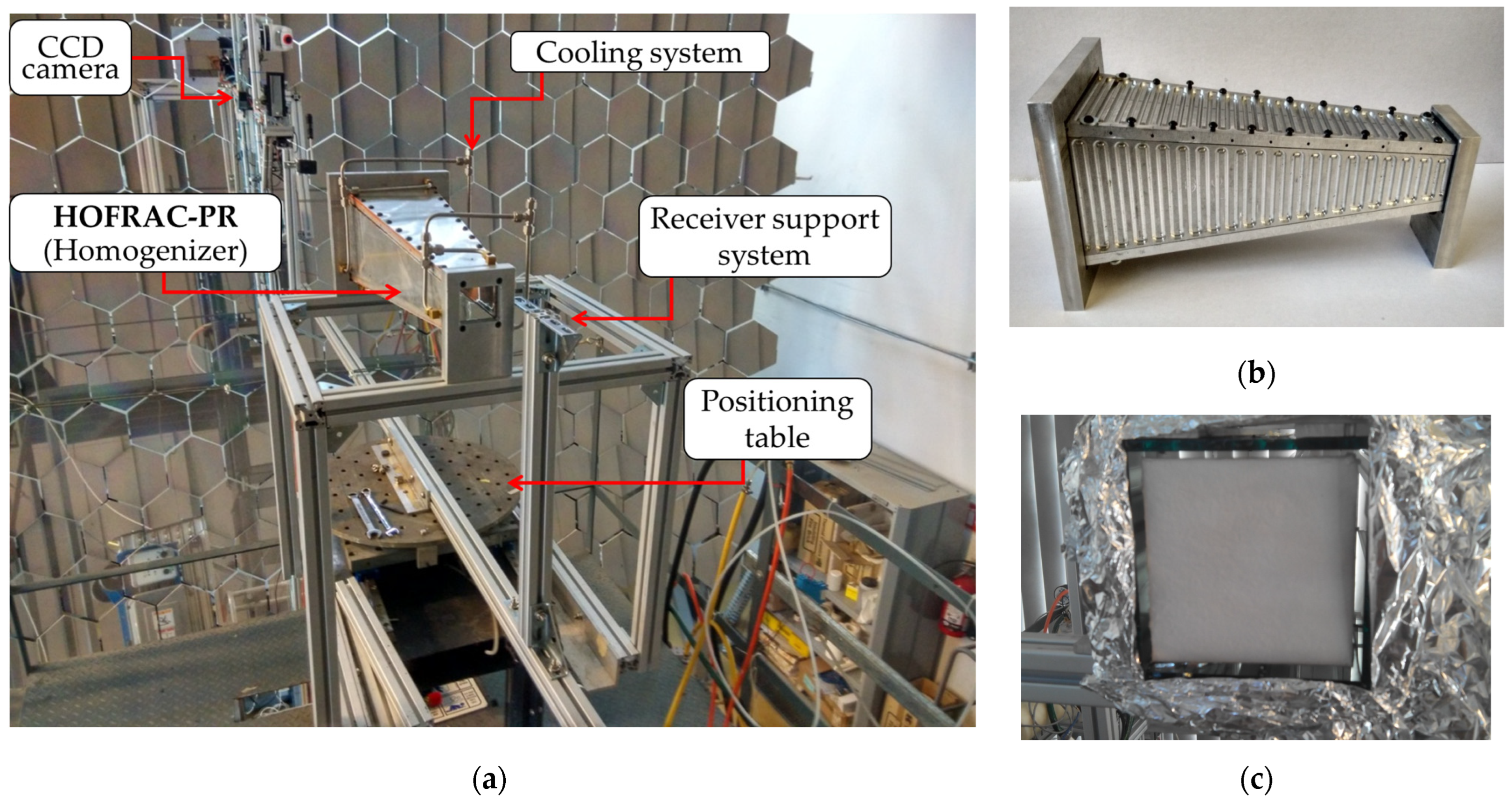
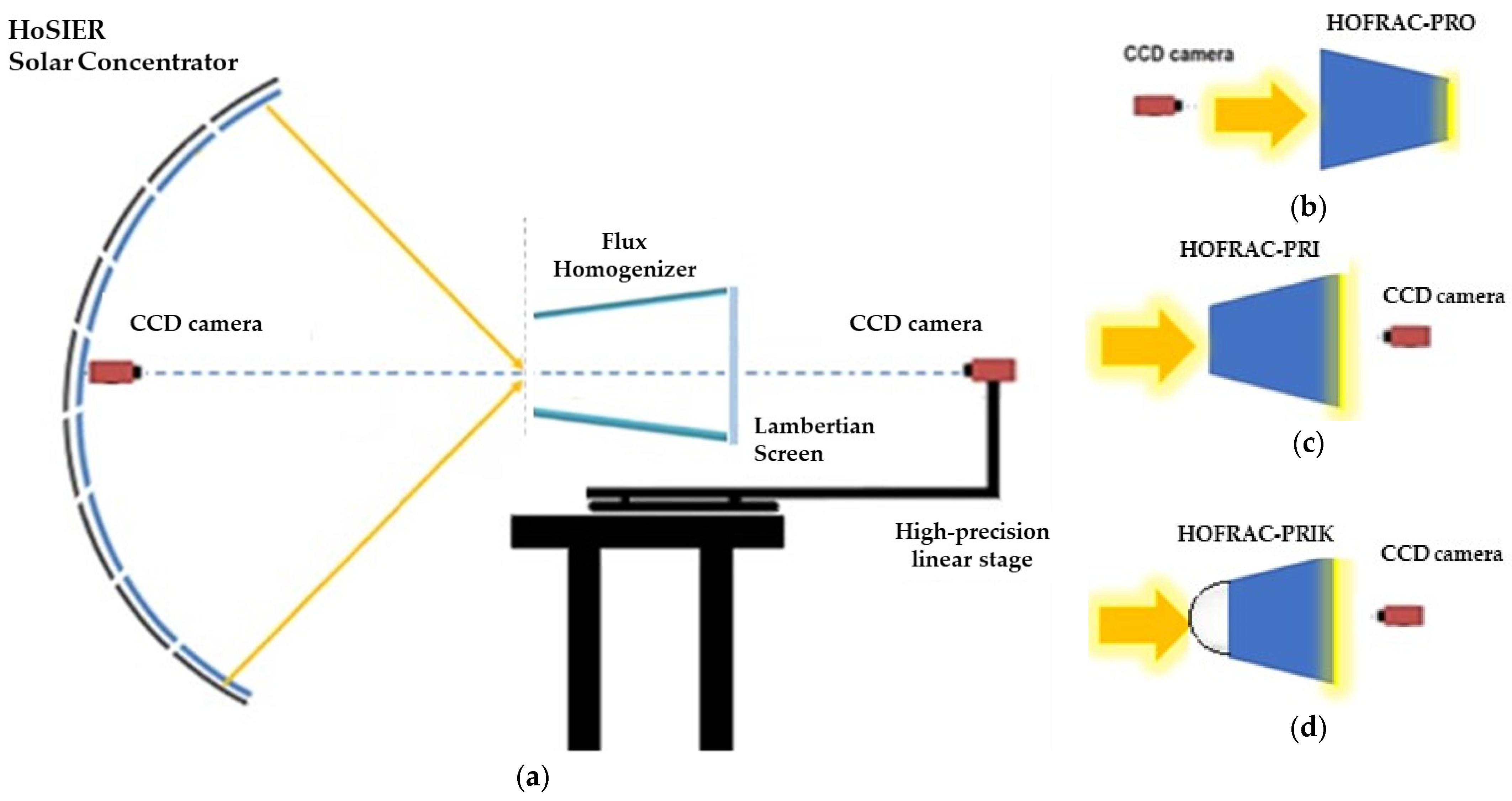
The radiative flux homogenization experiments were conducted at the High-Flux Solar Furnace (HoSIER) at Instituto de Energías Renovables of Universidad Nacional Autónoma de Mexico. A previous device, the High-Flux Radiative Homogenizer with Refrigerated Walls (HOFRAC-PR, its acronym in Spanish) (
Figure 1a) [
12], was employed for this purpose.
Figure 1b provides a view of the HOFRAC-PR internal cooling system and the refrigerant flow path inside the device’s flat walls. The prototype homogenizer has an initial length of 50 cm, with a square front face measuring 14 × 14 cm
2 and a back face of 5 × 5 cm
2.
The optical design of the HOFRAC-PR was based on computational simulations using the ray-tracing method with the SolTrace v3.4.0 software. After determining the optimal configuration of the homogenizer for HoSIER, a hollow flux homogenizer with an internal reflective square cross-section, in the shape of a truncated pyramid, was constructed.
To characterize the flux distribution along the prototype, a CCD camera was aligned with the optical axis of the concentrator and the HOFRAC-PR entrance (
Figure 1a). The camera and a Lambertian target used as a receiver (
Figure 1c) were mounted on a support structure anchored to the HoSIER positioning table. While the HOFRAC-PR remained stationary, the camera-target structure was moved independently, allowing images of the flux distribution inside the device to be captured at 1 cm intervals.
Multiple targets were required for imaging along the homogenizer due to the variable geometry of the HOFRAC-PR. Five Lambertian targets with different areas were constructed, each covering a 10 cm section inside the homogenizer. The critical length, where the highest uniformity was achieved, was found to be 21 cm with target 3, yielding a uniformity value of 0.0781 [
12].
Beyond 30 cm, no significant improvement in uniformity was observed, and the energy density on the receiver decreased considerably. Based on these findings, a new prototype, named HOFRAC-PRO (O for optimized), was developed, reducing the homogenizer length to 21 cm, starting from the larger cross-sectional face.
When the modified homogenizer was characterized using the aforementioned methodology, the observed flux distribution deviated from expectations, differing from previous experimental results and ray-tracing simulations. Three potential issues affecting the uniform flux in the prototypes were identified as described below.
2.1. Problem 1: Homogenizer Manufacturing
The first hypothesis attributed discrepancies to optical issues related to the device’s manufacturing. Handling during HOFRAC-PR experiments and subsequent modifications led to the deterioration of the internal reflective walls, which no longer maintained the reflectance of the original design. To address this, the reflective material (Alanod) was removed, and the aluminum surfaces were polished to a mirror finish.
Prototyping issues can arise during two main stages. In Stage 1, “Experimentation”, potential issues include thermal damage, delamination, deformation, internal stress, and distortion. In Stage 2, “Redesign and machining”, challenges include mismatched seams, dimensional inaccuracies, irregular surface finishes, and modifications to the cooling system.
During the optimization from HOFRAC-PR to HOFRAC-PRO, the homogenizer length was shortened, the cooling system was modified, and the reflective materials were removed. Despite these adjustments, neither the previously observed nor the simulated flux distribution could be reproduced.
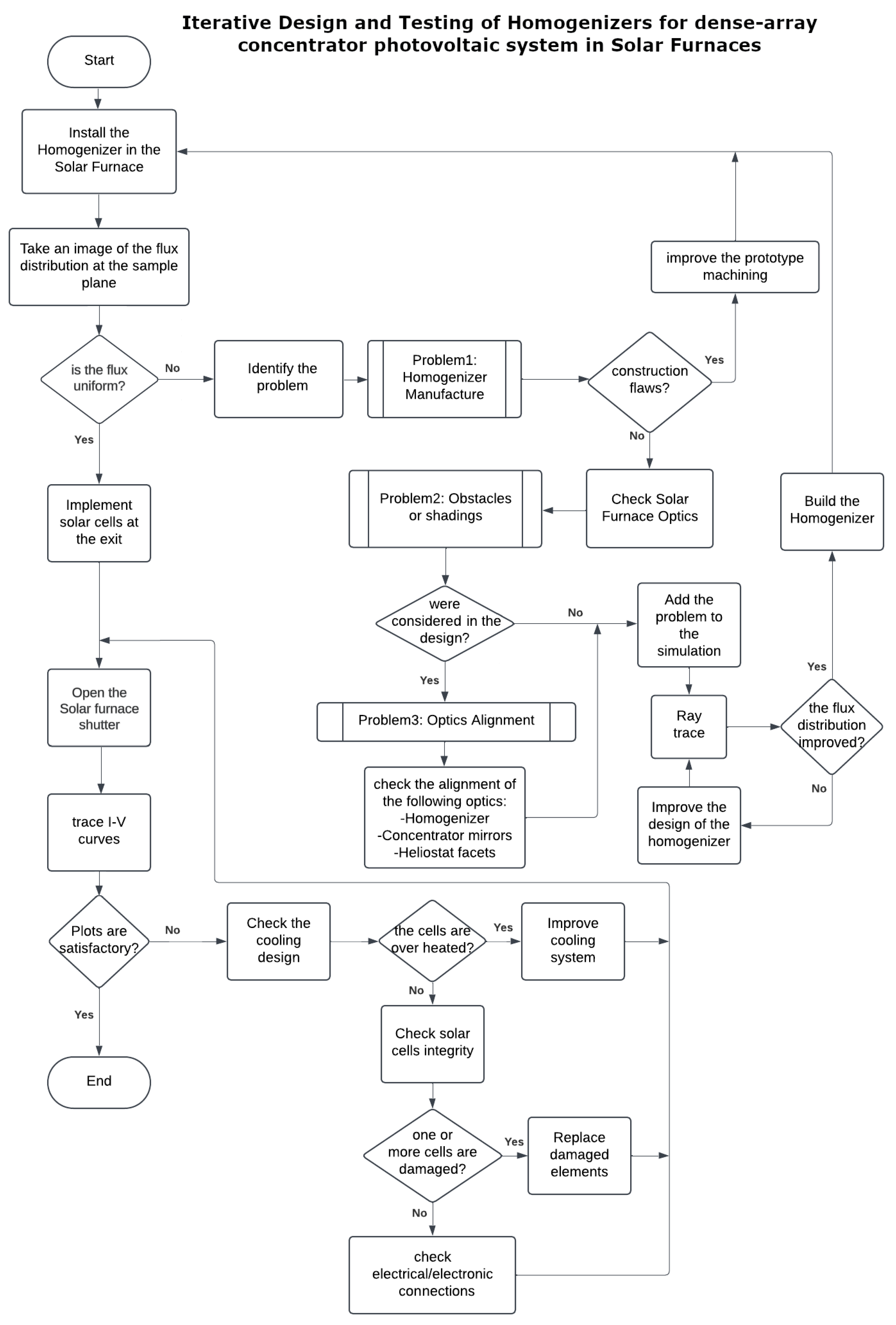
To address these discrepancies between the models and the experimental results, an iterative algorithm was proposed to determine the optimal homogenizer configuration for achieving a uniform flux distribution for concentrator photovoltaic devices characterized in a solar furnace. This algorithm was developed based on previous prototype homogenizers, optimization of ray-tracing software for flux homogenization, and a review of similar homogenizer devices tested in solar furnace facilities.
The proposed iterative algorithm for the design of homogenizers in solar furnaces is presented as a flowchart in
Figure 2.
Following the algorithm, the process of enhancing flux uniformity validated through both experimental and theoretical investigations using ray-tracing simulations suggested that obstacles between the concentrator and the heliostat were a limiting factor.
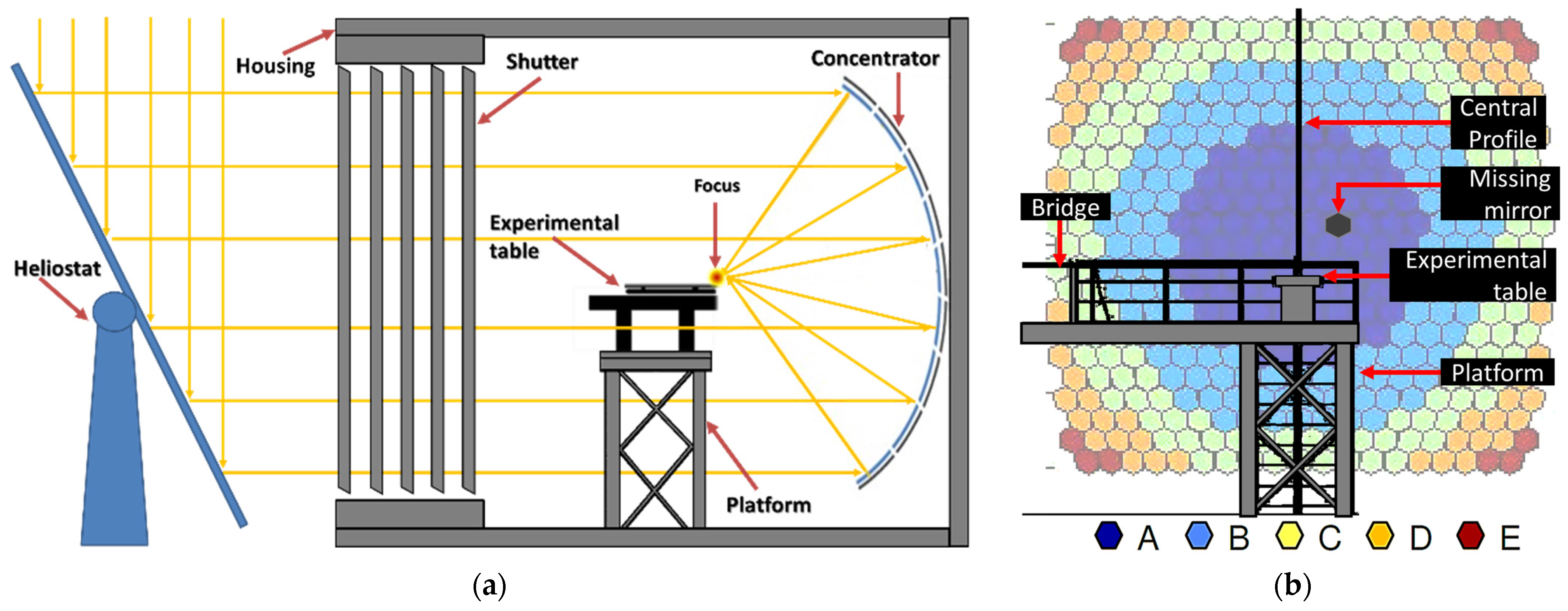
2.2. Problem 2: Obstacles and Shadows
Objects between the heliostat and concentrator, inherent to the solar furnace setup, e.g., shutter, platform, and positioning/experimentation table (
Figure 3a), may affect the flux uniformity at the homogenizer exit. In
Figure 3b, the 409 facets of HoSIER are displayed, grouped into five categories based on their focal distance. The image also highlights the non-removable obstacles inherent to the facility; the non-removable obstacles include essential structural elements such as the attenuator and experimental platform shadows cast by the partially closed shutter (
Figure 3a), which create band-like patterns on the concentrator mirrors (
Figure 3b).
Among the independent obstacles of the facility, there is the central profile that holds the camera, which serves to monitor the experiments and image acquisition, as well as the homogenizer itself. Other obstacles independent of the installation may be inherent to the maintenance of the facility, such as dirt on the first and second optical elements, missing concentrator mirrors (damaged or removed for maintenance), and devices or materials that were forgotten from other experimental campaigns.
2.3. Problem 3: Optical Alignment
As seen in
Figure 4a, the current flux distribution in the focal plane of HoSIER differs from the results reported in 2015 (the year when the first optical characterization of HoSIER was conducted), indicating a misalignment of the mirror. By comparing the normalized distribution profiles with the maximum values of both distributions, it is observed that the spot in 2024 does not present a symmetric distribution. This is also evident from the graph in
Figure 4a, where both profiles are normalized, and the maximum value of the 2024 distribution does not reach unity at the y-axis. The hypothesis of the misalignment of the concentrator mirrors is confirmed through the radiative characterization of the furnace’s spot, using a Gardon-type radiometer. The peak power measured was 6 kW/m
2, compared to the 18 kW/m
2 reported in [
13] and 10 kW/m
2 reported in [
14].
If this reduction in peak power were solely due to mirror dirt, a reduction in the average flux intensity at the output of the HOFRAC-PRO would be expected, while maintaining uniformity in the radiative flux distribution. Since this is not the case, it is suggested that the heterogeneity in the flux distribution on the target is caused by a misalignment of a significant number of concentrator mirrors in HoSIER. The spots generated by these misaligned mirrors are shown in
Figure 4b; the images formed by the reflection of the mirror that are not focusing on the same focal point are labeled in
Figure 4b with numbers. The numbered spots (1 to 5) do not represent all the misaligned mirrors, but rather highlight the issue.
In addition to the experimental images of the HoSIER spot, where the out-of-focus mirror spots are visible, ray-tracing simulations were conducted to determine the main factor negatively affecting the uniformity of the radiative flux at the output of HOFRAC-PRO.
3. Ray-Tracing Simulation
Simulations were performed using the SolTrace ray-tracing program, modeling the configuration of the 409 hexagonal spherical mirrors of the HoSIER concentrator. To reduce uncertainty in peak values at the homogenizer output and maximize the number of simulated rays, only the radiation from the heliostat that passes through the attenuator was considered, modeling the heliostat as a light grid using flat rectangular surfaces with reflective optical properties; the width of the rectangles represents the percentage of the attenuator opening.
The obstacles in the laboratory described in Problem 2 were also modeled. Since SolTrace does not allow the input of complex or free-form geometries, the central coordinates of these and other elements that interfere with the attenuator and concentrator were added to the concentrator stage at the corresponding distance, modeled as flat rectangular surfaces, and duplicated to simulate volumes.
The misalignment of mirrors currently present in HoSIER, as described in Problem 3, was approximated in the modeling process by reorienting 12 out of the 409 mirrors in the concentrator. These 12 selected mirrors are in Group A of the concentrator (Group A consists of 35 central mirrors with a focal distance of 3.75 m). The 12 mirrors were randomly but symmetrically oriented toward Quadrant 3 within the focal plane, covering a diameter of 12 cm. The flux distribution generated solely by these 12 mirrors is shown in
Figure 5a.
The number of selected mirrors and the degree of misalignment are representative of the problem. However, a qualitative comparison between the experimental image in
Figure 4b and the simulated distribution in
Figure 5b suggests that the actual number of misaligned mirrors is higher. When the 12 misaligned mirrors are integrated into the model alongside the remaining 397, their contribution becomes nearly imperceptible in the central region.
The alignment of the optics of the concentrator, following the methodology described in Martínez-Manuel et al. (2024) [
15], is expected to fully quantify both the number of misaligned mirrors and the degree of misalignment for each mirror by the end of the process.
Regarding the modeling of homogenizers, as part of the iterative prototype design process, two new configurations were modeled for the HOFRAC-PRO. The first, called HOFRAC-PRI (I for inverted), is the same instrument placed upside down (with the smaller area opening facing toward the concentrator mirror), to reduce the number of reflections from the central concentrator mirrors and minimize absorption losses in the homogenizer walls; additionally, the output area is increased to accommodate a higher number of solar cells with a concentration factor estimated by simulations around 1250 suns. In the case of Problem 3, to reduce the heterogeneity in the radiative flux due to defocused mirrors, the HOFRAC-PRI was modeled with the optics of a 12 cm Köhler sphere with the refractive properties of quartz at the homogenizer entrance, similar to what was proposed by Coughenour et al. (2012) [
16]; this homogenizer was referred to as HOFRAC-PRIK.
4. Simulation Results
In the following figures showing ray-tracing simulations for the homogenizer, the symbols used correspond to the operation conditions listed in
Table 1.
Figure 6 shows the effect of obstacles on the radiative flux distribution at the output of the homogenizer in its optimized configuration: HOFRAC-PRO. In
Figure 6a, the radiative flux distribution at the HOFRAC-PRO output is shown, along with the radiative flux uniformity degree (U), using Equation (1).
where
is the standard deviation of the flux intensity distribution values, and
is the average of these values. In
Figure 6a–d, the average flux distribution at the homogenizer output, the output area, and the symbols used to recognize the corresponding configuration and obstacles are provided in
Table 1.
As shown in
Figure 6a–d, according to the mathematical model, the uniformity values of HOFRAC-PRO are affected by all of the selected obstacles. The uniformity decreases due to both facility obstacles and the shadows cast by the heliostat at smaller openings, as seen in
Figure 6b. It is also evident from
Figure 6c,d that a small percentage of misaligned or missing mirrors can significantly reduce the system’s efficiency. Since most of the obstacles cannot be removed because they are part of the facility and the experimental setup, this version of the homogenizer is discarded for photovoltaic applications.
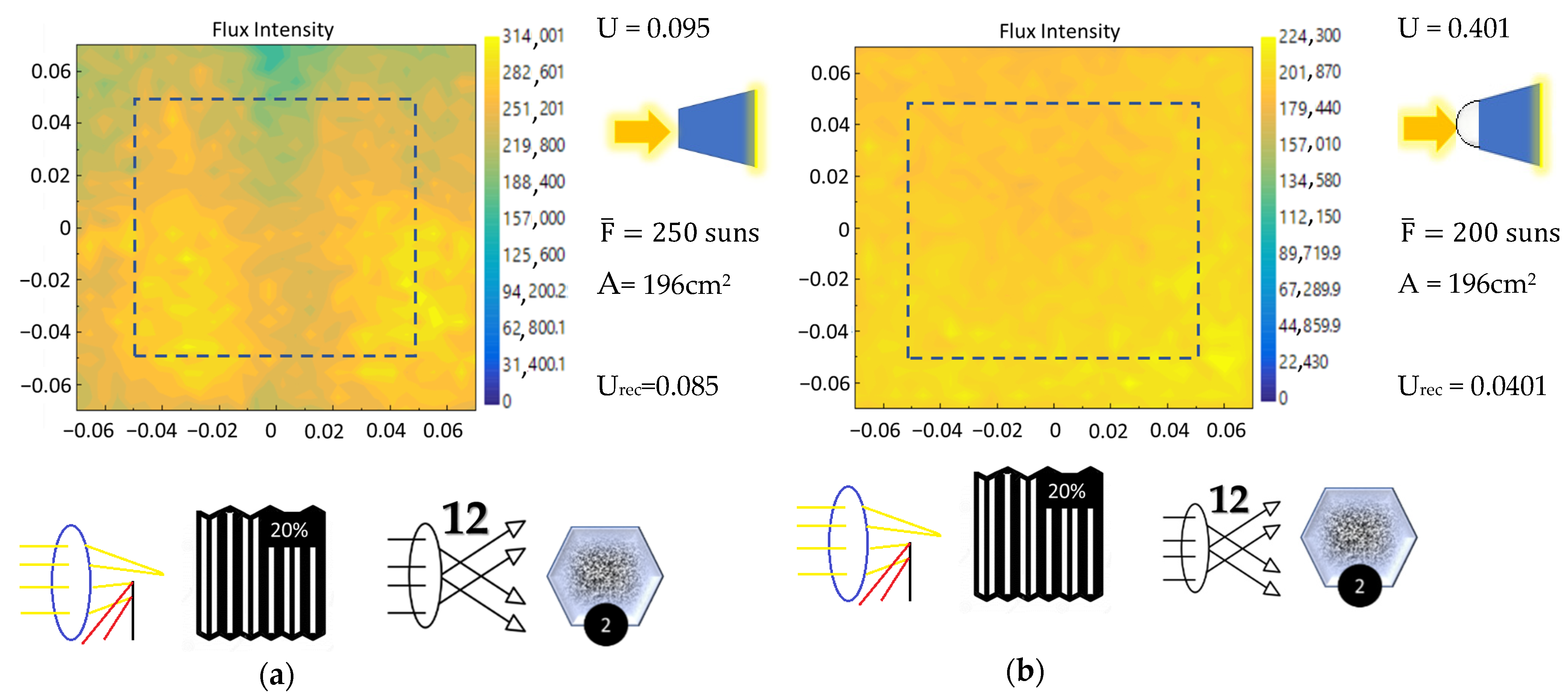
The flux distribution at the output of the homogenizer HOFRAC-PRI and HOFRAC-PRIK are shown in
Figure 7. For comparison purposes, in
Figure 6a,b, the uniformity U
rec of the HOFRAC-PRO output area is included.
As can be seen from the results in
Figure 7, the HOFRAC-PRIK homogenizer substantially improves the flux homogenization despite the presence of all obstacles. Therefore, this configuration was chosen for the experimental evaluation of the photovoltaic cell arrangement. It is important to note that the number of misaligned mirrors considered in the simulation and their degree of misalignment were arbitrary; therefore, the same flux distribution at the homogenizer output is not expected. However, better homogenization in HOFRAC-PRIK compared to HOFRAC-PRI is anticipated. Consequently, the arrangement of photovoltaic cells was evaluated in both homogenizer configurations.
5. Experimental Methodology for the Characterization of the CPV Array with the Homogenizers
As mentioned in
Section 2, the flux distribution at the exit of each prototype was characterized using a CCD camera aligned with the optical axis of the concentrator and the entrance of the homogenizer. The camera, along with a Lambertian target serving as a receiver, was mounted on a support structure secured to the HoSIER positioning table. In this experiment, the optimized versions of the HOFRAC-PR remained stationary, and the camera-target structure was not repositioned. All images of the flux distribution were captured at the exit of each device.
Figure 8a shows the experimental setup configuration for the three homogenizer cases.
Figure 8b–d depict the camera positions for the HOFRAC-PRO, HOFRAC-PRI, and HOFRAC-PRIK configurations, respectively. The yellow arrow in each figure indicates the face through which the concentrated solar radiation is incident. In the HOFRAC-PRI and HOFRAC-PRIK configurations, a sandblasted Pyrex glass screen was placed at the homogenizer output to serve as a Lambertian target. For the HOFRAC-PRO configuration, a sandblasted aluminum refrigerated target was used.
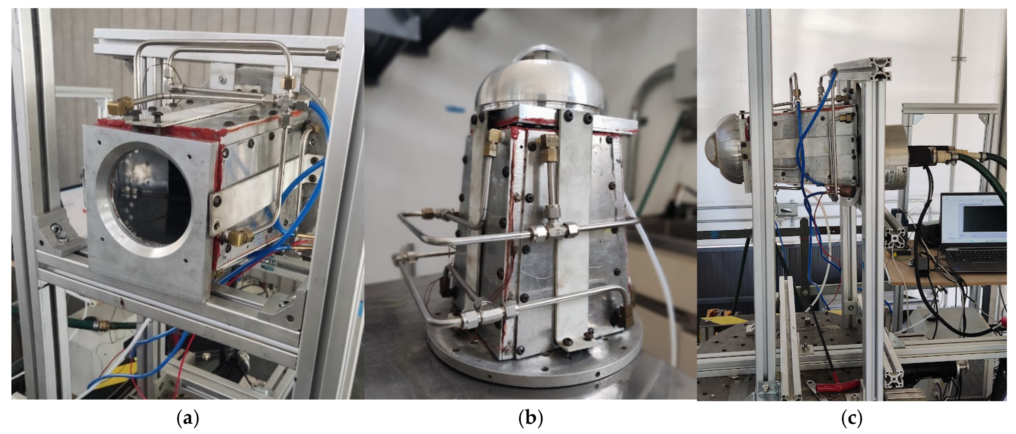
Figure 9a shows the HOFRAC-PRI installed on the positioning/experimental table.
Figure 9b depicts the HOFRAC-PRIK equipped with a cooling mask that injects air into the homogenizer to cool the sphere and dissipate heat from aluminum plate. This heat is generated by the overflow of the HoSIER’s focal spot.
To characterize a densely packed photovoltaic array with an area of 5 × 5 cm
2, a mounting system was designed to couple the CPV array to the output of the HOFRAC-PRI and HOFRAC-PRIK homogenizers. Since the output of both homogenizers measures 14 × 14 cm
2, the array is positioned at one corner of the homogenizer’s output (covering an area of 7 × 7 cm
2). The electrical response of the array is characterized under the incident flux distribution in that quadrant by measuring I–V curves using an IV tracer.
Figure 9c shows the coupling of the densely packed multijunction photovoltaic cell array to the HOFRAC-PRIK.
6. Results
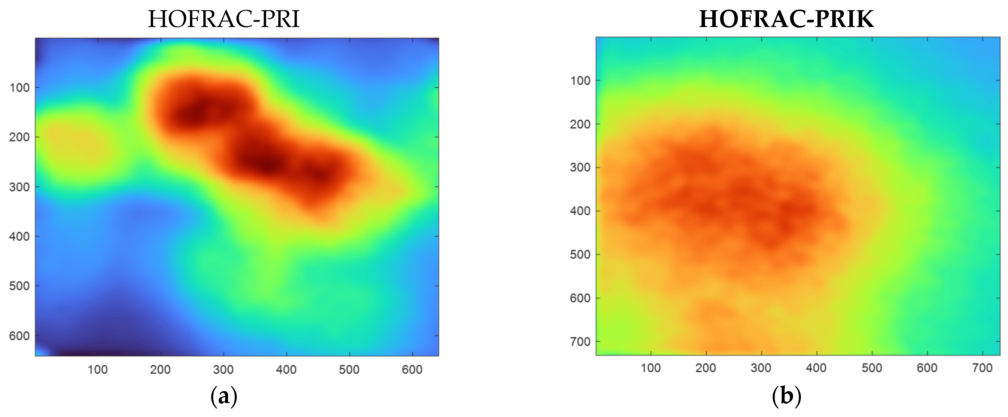
The flux distribution at the exit of the HOFRAC-PRI is presented in
Figure 10a. The image indicates a redistribution of the flux; however, the distribution remains non-uniform, with the highest intensity values (red colors) at the right side of the image, presenting a uniformity value of 0.433. This value represents a percentage difference of 131% compared to the simulated value. Although all obstacles were considered in the simulation, it is believed that the primary factor affecting the flux uniformity is the higher number of misaligned mirrors in the physical system, which exceeds the 12 mirrors accounted for in the simulation.
As discussed in previous sections, the flux distribution was improved by incorporating a sphere at the entrance of the homogenizer, resulting in a uniformity value of 0.304. The flux distribution at the exit of the HOFRAC-PRIK is depicted in
Figure 10b.
To illustrate the position of the CPV array, a sketch of the cells superposed over the image of the flux distribution at the exit of the HOFRAC-PRIK is shown in
Figure 11a. The image displays a division into quadrants, as the output of the HOFRAC-PRIK is a 14 × 14 cm
2 square, and the multijunction (III–V) photovoltaic cell array is densely packed in a 5 × 5 cm
2 square, shown in
Figure 11b. This allows the arrangement to be characterized with four different flux distributions by rotating 90° the photovoltaic array to characterize each quadrant and measure its electrical response.
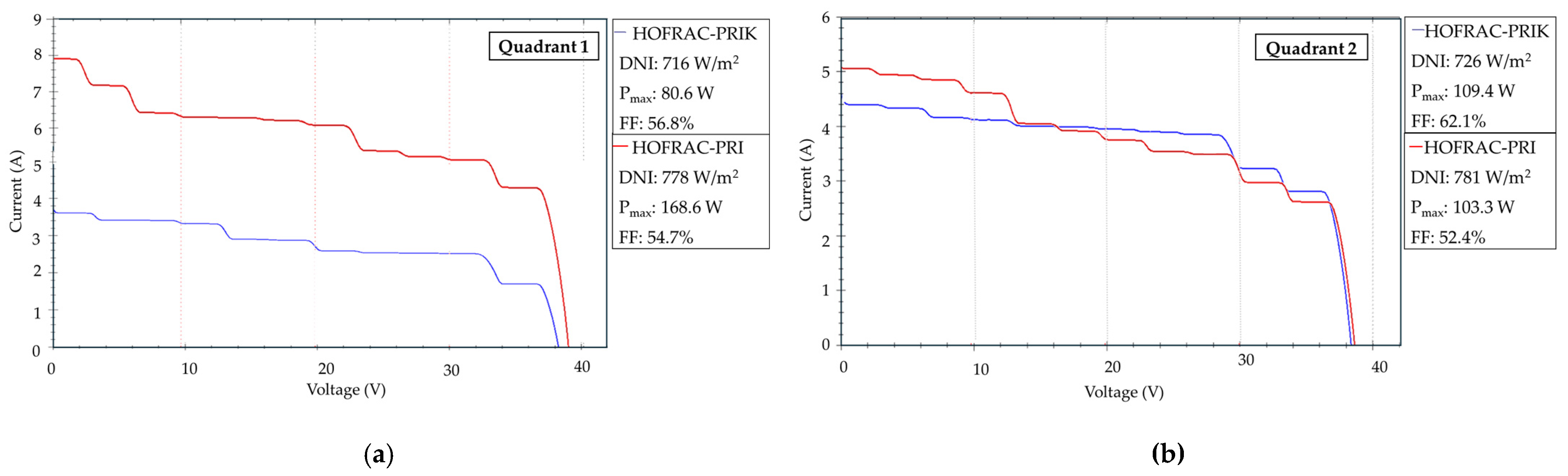
The graphs in
Figure 12 represent the I–V curves generated by an array of 12 multijunction photovoltaic (PV) cells subjected to the redistributed radiative flux distributions produced by the HOFRAC-PRI and HOFRAC-PRIK, respectively. The position of the PV array (quadrant) for both configurations is indicated in the corner of each plot.
In
Figure 12b,c, the I–V curves for the PV array located in Quadrants 2 and 3 show a significant improvement in the fill factor, achieving values of 62.1% and 59.1% with the HOFRAC-PRIK compared to 52.4% and 45.1% with the HOFRAC-PRI. This corresponds to an increase of 18.5% and 31.1%, respectively. These quadrants exhibit a higher radiative flux compared to Quadrants 1 and 4, as well as better uniformity values for the HOFRAC-PRIK, with UQ2
PRIK = 0.2820 and UQ3
PRIK = 0.1192. In contrast, the uniformity values for the HOFRAC-PRI in these quadrants are UQ2
PRI = 0.3529 and UQ3
PRI = 0.2930.
Despite the differing radiative conditions for the two homogenizers, the HOFRAC-PRIK produced more power in these quadrants. These results are consistent with the flux distribution depicted in
Figure 9b, where a higher energy concentration is observed on the left side of the Lambertian screen. This highlights the impact of the enhanced flux uniformity achieved by the combination of the homogenizer and the sphere on the electrical performance of the PV array.
Conversely, in
Figure 12a,d, corresponding to Quadrants 1 and 4, a higher energy output was observed with the HOFRAC-PRI, and a better flux distribution in each quadrant, with uniformity values of UQ1
PRI = 0.4255 and UQ4
PRI = 0.2512. The higher energy output aligns with simulations showing that the HOFRAC-PRI at its exit presents values of average flux 25% higher than the HOFRAC-PRIK.
For the specific case of the HoSIER system, the incorporation of the Köhler illumination technique, using a homogenizer combined with a sphere, improved the flux distribution uniformity and consequently enhanced the fill factor of the PV array. However, this improvement came at the cost of reduced radiative energy reaching the solar cells.
7. Discussion
Three instruments were developed to condition the concentrated solar radiation from HoSIER, enabling the evaluation of concentrator photovoltaic (CPV) cell arrays subjected to high radiative fluxes. The HOFRAC-PRO, featuring the smallest output aperture, theoretically demonstrated the highest average flux concentration value through ray-tracing simulations, achieving 1608 suns with the HoSIER attenuator fully open. Similarly, the HOFRAC-PRI theoretically surpassed 1000 suns, a standard benchmark for characterizing concentrator cells, allowing for the grouping of a larger number of photovoltaic cells.
However, the theoretical uniformity values could not be experimentally replicated in any of the versions. The effectiveness of the developed algorithm for improving the uniformity at the output of a homogenizer in a solar furnace is demonstrated through experimental evaluation, theoretical modeling, and continuous redesign. The algorithm identifies three main issues that hinder achieving homogenous flux, with the last one (Problem 3) partially addressed through the incorporation of a silica sphere for Köhler illumination. However, Problem 3 is dependent on the degree of misalignment of the mirrors and the number of misaligned mirrors. In the specific case of HoSIER, since some of the mirrors do not meet the acceptance angle for the sphere in the HOFRAC-PRIK system, a mirror alignment campaign for the concentrator is required in addition to the homogenizer redesign dictated by the algorithm.
The characterization of the CPV array by quadrants revealed that a homogeneous flux is essential for accurately characterizing densely packed CPV arrays. The HOFRAC-PRIK optimized the flux uniformity in the presence of obstacles by incorporating Köhler illumination techniques. Nevertheless, achieving the optimal or simulated values requires precise alignment of the solar furnace’s concentrating optics.
Currently, the flux distribution at the output of the HOFRAC-PRIK is suboptimal for characterizing the concentrator photovoltaic devices. Although the fill factor of the array was improved by 10% in Quadrants 2 and 3, with the addition of the sphere, it remains far from the nominal value of 86% reported by Cisneros et al. (2019) [
17].
Regardless of homogenizer redesign for photovoltaic applications, the homogenization process in the solar furnace depends on various installation-specific, non-removable factors, collectively grouped under Problem 2 in the algorithm. Identifying and modeling these factors enables the assessment of homogenizer’s feasibility for a particular solar furnace configuration. Pereira et al. (2020) [
10] presented a homogenizer for a solar furnace with a beam-down configuration, where both the secondary mirror and its supporting structure are obstacles requiring modeling. If feasible, removing the beam-down system and orienting the homogenizer horizontally could improve the uniformity of the flux at the output of the homogenizer.
Solar furnaces like HoSIER are versatile laboratories for various research applications. Optimizing the design of a device to redistribute radiative flux can positively impact the prototypes requiring a lower flux uniformity, such as volumetric receivers used in thermochemical applications [
18]. For reactors with smaller receiver areas, the HOFRAC-PRO could be used, while the HOFRAC-PRI might be suitable for larger area receivers, depending on the required flux intensity and uniformity.
The homogenizer operating conditions can vary based on the optical configuration of solar furnaces, as outlined in Problem 3, and may be influenced by the inherent facility obstacles described in Problem 2. The experiments requiring variation in homogenized flux intensity, such as those using venetian blinds, in an on-axis solar furnace like HoSIER, may differ from an off-axis furnace like the High-Flux Solar Furnace (HFSF) at the National Renewable Energy Laboratory (NREL) [
19]. Both systems may employ a similar attenuation mechanism; however, in HoSIER, this mechanism is located between the concentrator and the heliostat, whereas in the HFSF, it is positioned between the concentrator and the homogenizer.
This study highlights the importance of considering the solar furnace attenuation system as an obstacle in ray-tracing simulations. This consideration is crucial because heterogeneous regions in the flux distribution at the homogenizer’s output may form, depending on the distance between the attenuator and each optical element in the system [
20]. For a solar furnace designed to operate with highly concentrated and homogeneous fluxes, an iris-type attenuation system or more sophisticated, thinner venetian blind system could be considered.
The limitations of this study are primarily associated with the alignment campaign for the concentrator mirrors of HoSIER. According to ray-tracing simulations, the sphere may be sufficient to correct the heterogeneities caused by obstacles at the homogenizer’s output and even improve the flux distribution when the concentrator mirrors exhibit slight misalignment. However, the degree of uniformity achievable at the HOFRAC-PRIK’s output will depend on minimizing the misalignment angle of each concentrator mirror. The methodology proposed in [
15] is ideal for the operation of systems employing out-of-focus optics, such as those presented in this work using homogenizers.
Future work, following the completion of the HoSIER alignment campaign, will focus on applying Köhler illumination techniques to the HOFRAC-PRO or a new homogenizer with a smaller cross-sectional area to increase the energy density at the output. Additionally, optimizing the heat removal system within these cavities will be essential to improve overall system efficiency.
This conclusion reinforces the need for precise mirror alignment and highlights the potential of Köhler illumination techniques for advancing homogenizer performance in solar furnaces.
8. Conclusions
An optical evaluation was carried out on a prototype of a radiative flux homogenizer specifically designed and built for the Solar Furnace at Instituto de Energías Renovables of Universidad Nacional Autónoma de México. The evaluation was both theoretical and experimental. HOFRAC-PR was developed in three versions, with each improved based on theoretical and experimental results. All three versions were evaluated in the solar furnace by capturing images of the radiative flux distribution, and ray-tracing simulations were performed in SolTrace to replicate the experimental conditions, considering the elements affecting the flux distribution and the specific characteristics of each version.
The experimental images of the furnace spot clearly reveal the effects of misaligned mirrors. The simulations confirm that, under the current optical conditions of HoSIER, the HOFRAC-PRO does not homogenize the radiative flux sufficiently for implementing a photovoltaic concentration system. This is primarily due to mirror misalignment. To address this issue, different homogenizer configurations were tested through ray-tracing simulations. An inverted configuration, called HOFRAC-PRI, was enhanced by adding a refractive sphere at the input during the ray-tracing simulation, generating the version called HOFRAC-PRIK. The sphere’s function is to redirect the rays concentrated by the misaligned mirrors to the center of the homogenizer, in addition to inverting the homogenizer’s position. This significantly improved the flux homogenization, changing the simulated uniformity from 0.095 without the sphere to 0.04 with the refractive sphere.
Additionally, experiments were conducted to evaluate the performance of a densely packed photovoltaic cell array, which requires flux uniformity for optimal operation. By analyzing the I–V curves and the fill factor of each curve, it was determined that adding a refractive sphere to the homogenizer integrated into HoSIER in the current state substantially improved the radiative flux distribution. It was found that the fill factor for Quadrants 1, 2, and 3 increased by 2%, 10%, and 14%, respectively, while Quadrant 4 saw a 2% reduction. The sphere helps increase the uniformity of incident radiation on the concentrated photovoltaic cell array, improving the fill factor. However, not all quadrants show an increase in the maximum power delivered by the system under similar irradiance and temperature conditions. Quadrants 1 and 2 generate 58% more electrical power without the sphere, while Quadrants 2 and 3 show better performance with the sphere, with an 18% increase. To scale this array, it is necessary to optimize the interconnection between quadrants through series-parallel connections, and the optimal configuration involves minimizing current variations between arrays. Therefore, the homogenizer that would best serve to scale the array is the HOFRAC-PRIK. This is observed when calculating the standard deviation of peak currents between quadrants, which were 0.9 amperes for the HOFRAC-PRI and 0.8 amperes for the HOFRAC-PRIK.
Author Contributions
Conceptualization, validation, and formal analysis, E.A.R. and C.A.E.G.; methodology, C.A.E.G.; software, E.A.R.; validation, E.A.R. and N.A.C.-C.; investigation, writing—original draft preparation and writing—review and editing, E.A.R., N.A.C.-C. and C.A.E.G.; visualization, supervision, project administration, and funding acquisition, C.A.E.G. All authors have read and agreed to the published version of the manuscript.
Funding
This research was funded by Laboratorio Nacional de Concentración Solar y Química Solar.
Institutional Review Board Statement
Not applicable.
Informed Consent Statement
Not applicable.
Data Availability Statement
No data are available due to privacy and institutional restrictions.
Acknowledgments
The authors would like to thank the National Council for Humanities, Science, and Technology (CONAHCyT) for the postdoctoral fellowship awarded through the Researches for Mexico Program to Ernesto Anguera Romero and to DGAPA-UNAM for the postdoctoral fellowship awarded to Nidia Aracely Cisneros Cárdenas. The authors also express their gratitude to project DGAPA-UNAM PAPIIT-AG101525 for providing the financial support that made this work possible.
Conflicts of Interest
The authors declare no conflicts of interest. The funders had no role in the design of the study; in the collection, analyses, or interpretation of data; in the writing of the manuscript; or in the decision to publish the results.
Correction Statement
This article has been republished with a minor correction to the Acknowledgments. This change does not affect the scientific content of the article.
Abbreviations
The following abbreviations are used in this manuscript:
| CPV | Concentrated photovoltaic |
| CSR | Concentrated solar radiation |
| HTF | Heat transfer fluid |
| CPC-CPVT | Compound parabolic concentrator–concentrated photovoltaic thermal system |
| HoSIER | (Spanish acronym) Solar Furnace at Instituto de Energías Renovables |
| HOFRAC-PR | (Spanish acronym) High-flux radiative homogenizer with refrigerated walls |
| CCD | Charge-coupled device |
| HOFRAC-PRO | (Spanish acronym) High-flux radiative homogenizer with refrigerated walls optimized |
| HOFRAC-PRI | (Spanish acronym) High-flux radiative homogenizer with refrigerated walls inverted |
| HOFRAC-PRIK | (Spanish acronym) High-flux radiative homogenizer with refrigerated walls with Köhler illumination |
| U | Uniformity degree |
| UQ1PRI | Flux uniformity at the exit of the HOFRAC-PRI for Quadrant 1 |
| UQ2PRI | Flux uniformity at the exit of the HOFRAC-PRI for Quadrant 2 |
| UQ3PRI | Flux uniformity at the exit of the HOFRAC-PRI for Quadrant 3 |
| UQ4PRI | Flux uniformity at the exit of the HOFRAC-PRI for Quadrant 4 |
| UQ1PRIK | Flux uniformity at the exit of the HOFRAC-PRIK for Quadrant 1 |
| UQ2PRIK | Flux uniformity at the exit of the HOFRAC-PRIK for Quadrant 2 |
| UQ3PRIK | Flux uniformity at the exit of the HOFRAC-PRIK for Quadrant 3 |
| UQ4PRIK | Flux uniformity at the exit of the HOFRAC-PRIK for Quadrant 4 |
| Average solar flux, suns |
| A | Receiver area, cm2 |
| Urec | Uniformity degree of area delimited by the rectangle |
| I–V | Intensity–voltage |
| PV | Photovoltaic |
| FF | Fill factor |
| RXX | Refraction-Reflection-Reflection |
References
- Green, M.A.; Dunlop, E.D.; Siefer, G.; Yoshita, M.; Kopidakis, N.; Bothe, K.; Hao, X. Solar cell efficiency tables (Version 61). Prog. Photovolt. Res. Appl. 2023, 31, 3–16. [Google Scholar] [CrossRef]
- Ferrer-Rodríguez, J.P.; Saura, J.M.; Fernández, E.F.; Almonacid, F.; Talavera, D.L.; Pérez-Higueras, P. Exploring ultra-high concentrator photovoltaic Cassegrain-Koehler-based designs up to 6000×. Opt. Express 2020, 28, 6609–6617. [Google Scholar] [CrossRef]
- Winston, R. Simple Köhler homogenizers for image-forming solar concentrators. J. Photonics Energy 2011, 1, 015503. [Google Scholar] [CrossRef]
- He, Y.L.; Wang, K.; Qiu, Y.; Du, B.C.; Liang, Q.; Du, S. Review of the solar flux distribution in concentrated solar power: Non-uniform features, challenges, and solutions. Appl. Therm. Eng. 2019, 149, 448–474. [Google Scholar] [CrossRef]
- Yu, Q.; Li, Z.; Zhao, W.; Zhang, G.; Xiong, X.; Wu, Z. Modeling and control strategy optimizing of solar flux distribution in a four quadrant and adjustable focusing solar furnace. Appl. Energy 2024, 363, 123121. [Google Scholar] [CrossRef]
- Glaser, P.E.; Chen, M.M.; Berkowitz-Mattuck, J. The flux redistributor An optical element for achieving flux uniformity. Sol. Energy 1963, 7, 12–17. [Google Scholar] [CrossRef]
- Chen, M.M.; Berkowitz-Mattuck, J.B.; Glaser, P.E. The Use of a Kaleidoscope to Obtain Uniform Flux Over a Large Area in a Solar or Arc Imaging Furnace. Appl. Opt. 1963, 2, 265–271. [Google Scholar] [CrossRef]
- Shanmugam, M.; Maganti, L.S. Improvement of uniformity of irradiance on truncated compound parabolic concentrator by introducing the homogenizer ratio. Renew. Energy 2023, 204, 580–592. [Google Scholar] [CrossRef]
- Vu, D.T.; Vu, H.; Vu, N.H. A homogeniser inspired by the crustacean’s eye with uniform irradiance distribution and high optical efficiency characteristics for concentrated photovoltaics system. Sol. Energy 2021, 221, 87–98. [Google Scholar] [CrossRef]
- Pereira, J.C.G.; Rodríguez, J.; Fernandes, J.C.; Rosa, L.G. Homogeneous Flux Distribution in High-Flux Solar Furnaces. Energies 2020, 13, 433. [Google Scholar] [CrossRef]
- Arguelles-Arizcun, D.; Fernández-García, A.; Buendía-Martínez, F.; Rodriguez, J.; Martínez, I.C.; Martínez-Arcos, L. New set-up to test secondary concentrators under real solar radiation with high concentration. AIP Conf. Proc. 2019, 2126, 160001. [Google Scholar] [CrossRef]
- Anguera, E.; Estrada, C.A. A new approach for evaluating flux uniformity for dense array concentrator photovoltaic cells. Sol. Energy 2018, 171, 330–342. [Google Scholar] [CrossRef]
- Pérez-Enciso, R.A. Caracterización Óptica y Térmica del Horno Solar del IER, Universidad Nacional Autonoma de México. 2015. Available online: https://hdl.handle.net/20.500.14330/TES01000724555 (accessed on 10 January 2024).
- Figueroa Hernández, E. Sistema de Evaluación Rápida de Flujo Solar Concentrado Con Enfriamiento Por Aire; Universidad Nacional Autonoma de México: México City, Mexico, 2024; Available online: https://hdl.handle.net/20.500.14330/TES01000853476 (accessed on 9 December 2024).
- Martínez-Manuel, L.; Arreola-Ramos, C.E.; Balbuena-Ortega, A.; Arancibia-Bulnes, C.A. Development of an optical method to align a high-flux solar furnace. Appl. Opt. 2024, 63, 8808–8817. [Google Scholar] [CrossRef]
- Coughenour, B.; Angel, R. XRX-Köhler optical design and illumination optimization. Int. Opt. Des. Conf. 2014, 9293, 929312. [Google Scholar] [CrossRef]
- Cisneros-Cardenas, N.A.; Cabanillas-López, R.E.; Pérez-Enciso, R.A.; García-Gutiérrez, R. Caracterización térmica y eléctrica de un sistema fotovoltaico de alta concentración de disco parabólico. Rev. De Ing. Eléctrica 2019, 3, 16–21. [Google Scholar] [CrossRef]
- Cisneros-Cárdenas, N.A.; Pérez-Enciso, R.A.; Pérez-Rábago, C.A.; Calleja-Valdez, R.A.; Maytorena-Soria, V.M.; García-Gutiérrez, R.; Cabanillas-Lopez, R.E. Thermal experimental study of a volumetric receiver-reactor using a Mini-Solar furnace. Appl. Therm. Eng. 2023, 234, 121276. [Google Scholar] [CrossRef]
- Bingham, C.E.; Scholl, K.L.; Lewandowski, A.A.; Scholl, K.L. Flux Attenuation at NREL’s High-Flux Solar Furnace. In Proceedings of the ASME/JSME/JSES International Solar Energy Conference, Maui, HI, USA, 19–24 March 1995. [Google Scholar]
- Kreske, K. Optical design of a solar flux homogenizer for concentrator photovoltaics. Appl. Opt. 2002, 41, 2053. [Google Scholar] [CrossRef]
Figure 1.
(a) HOFRAC-PR installed at HoSIER, (b) HOFRAC-PR without cover showing the cooling system, and (c) Lambertian target.
Figure 1.
(a) HOFRAC-PR installed at HoSIER, (b) HOFRAC-PR without cover showing the cooling system, and (c) Lambertian target.
Figure 2.
Flowchart illustrating the evolutionary prototyping process for homogenizers in solar furnaces used.
Figure 2.
Flowchart illustrating the evolutionary prototyping process for homogenizers in solar furnaces used.
Figure 3.
Inherent obstacles in Solar Furnace Facility. (a) Basic diagram of radiation attenuation in solar furnace and (b) Schematic front view of the 409 hexagonal concentrator mirrors of HoSIER with facility’s obstacles: bridge, platform, experimental table, and central profile.
Figure 3.
Inherent obstacles in Solar Furnace Facility. (a) Basic diagram of radiation attenuation in solar furnace and (b) Schematic front view of the 409 hexagonal concentrator mirrors of HoSIER with facility’s obstacles: bridge, platform, experimental table, and central profile.
Figure 4.
Radiative flux distribution in the focal plane of HoSIER. (a) Comparison between flux distribution profiles in the HoSIER focal plane in 2015 (optimal) and 2024 profile (current) at 100% attenuator opening; (b) radiative flux distribution in the focal plane at 10% attenuator aperture in 2024.
Figure 5.
Radiative flux distribution on the focal plane of HoSIER under the following conditions: (a) with only 12 misaligned concentrator mirrors; (b) with the entire set of concentrator mirrors, including the 12 misaligned ones.
Figure 5.
Radiative flux distribution on the focal plane of HoSIER under the following conditions: (a) with only 12 misaligned concentrator mirrors; (b) with the entire set of concentrator mirrors, including the 12 misaligned ones.
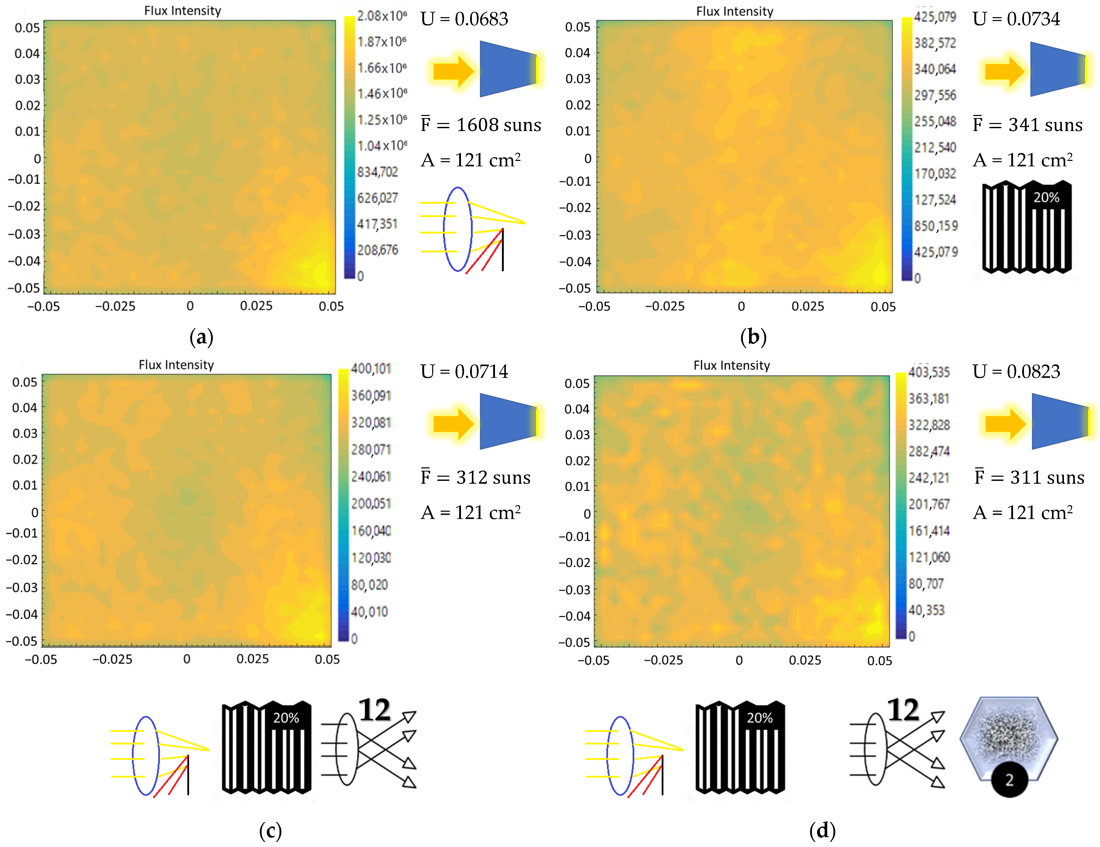
Figure 6.
Radiative flux distributions in different homogenizer configurations considering HoSIER obstacles. (a) HOFRAC-PRO with 100% attenuator opening, (b) HOFRAC-PRO with 20% attenuator opening, (c) HOFRAC-PRO with 20% attenuator opening and 12 misaligned mirrors, and (d) HOFRAC-PRO with 20% attenuator opening, 12 misaligned mirrors, and 2 damaged mirrors.
Figure 7.
Radiative flux distribution in homogenizer configuration for 20% attenuator opening, 12 misaligned mirrors, and 2 damaged mirrors; same configuration for (a) HOFRAC-PRI and (b) HOFRAC-PRIK.
Figure 7.
Radiative flux distribution in homogenizer configuration for 20% attenuator opening, 12 misaligned mirrors, and 2 damaged mirrors; same configuration for (a) HOFRAC-PRI and (b) HOFRAC-PRIK.
Figure 8.
Experimental setup. (a) Schematic diagram of the experimental configuration mounted on HoSIER. Homogenizer and camera configurations by experiment: (b) HOFRAC-PRO, (c) HOFRAC-PRI, and (d) HOFRAC-PRIK.
Figure 8.
Experimental setup. (a) Schematic diagram of the experimental configuration mounted on HoSIER. Homogenizer and camera configurations by experiment: (b) HOFRAC-PRO, (c) HOFRAC-PRI, and (d) HOFRAC-PRIK.
Figure 9.
Photographs of the homogenizers: (a) HOFRAC-PRI, (b) HOFRAC-PRIK, and (c) photovoltaic array coupled to HOFRAC-PRIK.
Figure 9.
Photographs of the homogenizers: (a) HOFRAC-PRI, (b) HOFRAC-PRIK, and (c) photovoltaic array coupled to HOFRAC-PRIK.
Figure 10.
Uniformity improvement at the exit of the homogenizer. (a) Radiative flux distribution at the HOFRAC-PRI. (b) Radiative flux distribution at the HOFRAC-PRIK.
Figure 10.
Uniformity improvement at the exit of the homogenizer. (a) Radiative flux distribution at the HOFRAC-PRI. (b) Radiative flux distribution at the HOFRAC-PRIK.
Figure 11.
(a) Radiative flux distribution at the HOFRAC-PRIK output divided into quadrants and (b) photovoltaic array mounted on a coupling mask.
Figure 11.
(a) Radiative flux distribution at the HOFRAC-PRIK output divided into quadrants and (b) photovoltaic array mounted on a coupling mask.
Figure 12.
I–V curve comparison for HOFRAC-PRI and HOFRAC-PRIK. (a) Quadrant 1, (b) Quadrant 2, (c) Quadrant 3, and (d) Quadrant 4.
Figure 12.
I–V curve comparison for HOFRAC-PRI and HOFRAC-PRIK. (a) Quadrant 1, (b) Quadrant 2, (c) Quadrant 3, and (d) Quadrant 4.
Table 1.
Ray-tracing simulation symbols for homogenizer configurations.
| Disclaimer/Publisher’s Note: The statements, opinions and data contained in all publications are solely those of the individual author(s) and contributor(s) and not of MDPI and/or the editor(s). MDPI and/or the editor(s) disclaim responsibility for any injury to people or property resulting from any ideas, methods, instructions or products referred to in the content. |
© 2025 by the authors. Licensee MDPI, Basel, Switzerland. This article is an open access article distributed under the terms and conditions of the Creative Commons Attribution (CC BY) license (https://creativecommons.org/licenses/by/4.0/).


