Article

Effect of Crystallization on Electrochemical and Tribological Properties of High-Velocity Oxygen Fuel (HVOF)-Sprayed Fe-Based Amorphous Coatings

by
Abdul Qadir Abbas
1,
Muhammad Arslan Hafeez
2,
Cheng Zhang
2,
Muhammad Atiq-ur-Rehman
1 and
Muhammad Yasir
1,2,*
1
Department of Materials Science and Engineering, Institute of Space Technology, Islamabad 44000, Pakistan
2
State Key Laboratory of Materials Processing and Die & Mould Technology, School of Materials Science and Engineering, Huazhong University of Science and Technology, Wuhan 430074, China
*
Author to whom correspondence should be addressed.
AppliedChem 2024, 4(3), 270-281; https://doi.org/10.3390/appliedchem4030017
Submission received: 19 April 2024 / Revised: 9 July 2024 / Accepted: 19 July 2024 / Published: 29 July 2024

Abstract

:
An Fe-based amorphous coating, with the composition Fe48Cr15Mo14C15B6Y2, was synthesized by the high-velocity oxygen fuel spray (HVOF) process on a substrate of AISI 1035. The effect of crystallization on the electrochemical and tribological properties of the HVOF-sprayed Fe-based coating was systematically studied. The XRD results validated the fully amorphous nature of the as-sprayed coating by showing a broad peak at 43.44° and crystallization of this coating after heat-treatment at 700 °C by demonstrating sharp peaks of Fe-, Mo-, and Cr-based carbides. After crystallization, an increase in the corrosion current density from 4.95 μAcm−2 to 11.57 μAcm−2 and in the corrosion rate from 4.28 mpy to 9.99 mpy, as well as a decrease in the polarization resistance from 120 Ωcm2 to 65.12 Ωcm2, were observed, indicating the deterioration of the corrosion resistance of the as-sprayed Fe-based coating. This can be attributed to the formation of porous ferrous oxide, providing an easy channel for charge transfer and promoting pit formation. However, a decrease in the coefficient of friction from 0.1 to 0.05 was observed, highlighting the significant improvement in the wear resistance of the Fe-based coating after crystallization. This can be associated with the precipitation of hard carbides (MxCy) at the boundaries of the crystallized regions.

1. Introduction

Fe-based bulk metallic glasses (BMGs), which have excellent anti-corrosion and anti-wear properties with high strength and hardness, are thought to be promising materials for various applications, including defense, aerospace, and automotive applications [1,2,3,4,5]. However, their large-scale applications have been restricted due to their intrinsic brittleness and lower toughness, attributed to their lower critical cooling rate and thickness limitation [6,7,8]. To overcome this deficiency, the utilization of BMGs as a corrosion and wear-resistant thin amorphous coating started in the last few decades. Among various BMG-based coatings, Fe-based amorphous coatings have achieved more interest in recent years [9,10,11].
Fe-based amorphous coatings demonstrate excellent mechanical properties compared to conventional alloy coatings [12,13,14]. These coatings do not possess structural defects, including interfacial defects, grain boundaries, and dislocations, and therefore exhibit superior corrosion resistance over crystalline alloy coatings [15,16]. Fe-based amorphous coatings can be deposited on a variety of substrates and used in various industrial applications, such as ships in the marine environment, containers for spent nuclear fuel, oil and gas industries, power stations, aerospace, energy, shipbuilding, and chemicals due to their lower maintenance requirements and prolonged service life [17,18,19]. Fe-based amorphous coatings can be deposited by different methods, such as the arc-spraying, laser-cladding, plasma-spraying, detonation gun-spraying, and high-velocity oxygen fuel (HVOF)-spraying techniques [20].
The high-velocity oxygen fuel (HVOF)-spraying process is one of the most widely used, most efficient, and low-cost methods of depositing thick, dense, homogenous, hard, corrosion-resistance, wear-resistant, oxidation-resistant, and high-performance coatings with a very low porosity percentage (<0.5%) at a moderate cost [21]. In the HVOF-spraying process, the feedstock powder, along with carrier gas, is sent into the combustion chamber and heated by the combustion of the mixture gas at high temperature. To achieve supersonic velocity, the melted/semi-melted particles are accelerated toward the substrate by the combustible gases through the de Laval nozzle and deposited on it in the form of a coating [22]. HVOF involves a short processing time, which minimizes the degradation of the starting feedstock powders and reduces the interaction between the molten powder stream and the surrounding atmosphere, thus reducing oxide formation [23]. Being a high-kinetic-energy process, the HVOF-spraying process significantly improves the inter-splat adhesion [24,25].
Sweitzer et al. [26] and Lucente et al. [27] reported an improvement in the corrosion resistance of Al- and Mg-based BMGs after crystallization due to the formation of nano-crystalline phases. The nano-crystalline phases are produced by the combination of the partial melting and pinning effect due to the flame temperature and the impinging of particles at supersonic velocity, respectively [28]. On the contrary, Ni- and Cu-based amorphous coatings have been reported to demonstrate a reduction in corrosion resistance after crystallization [29]. Similarly, Ha et al. [30,31] also reported a drop in the anti-corrosion properties of Fe-based coatings due to semi-crystallization. Yang et al. [19] investigated the effect of crystallization on the anti-corrosion properties of an Fe48Cr15Mo14C15Y2B6 amorphous coating and found that the anti-corrosion properties of the deposited coating were destroyed with the increase in the volume fractions of the crystalline phase. They associated this reduction in corrosion resistance with the pits initiated at the boundaries around the carbide precipitates. This passive region contained low (Cr, Mo)-oxide contents.
Although some works have previously been reported concerning the crystallization of Fe-based coatings, an in-depth study of the effect of crystallization on the corrosion and wear properties has not been reported so far. Therefore, in this work, we present a detailed analysis of the effect of crystallization on the microstructural, electrochemical, and tribological properties of Fe-based amorphous coatings. Crystallization resulted in the nucleation of Fe-, Mo-, and Cr-based carbides. The results indicate that the crystallized coating exhibits very high wear resistance, with a reduction in the corrosion resistance.

2. Materials and Methods

2.1. Materials

AISI 1035 plain carbon steel was selected as the substrate material due to its extensive usage in different industries. The obtained AISI 1035 steel plate was press-cut into four segments with dimensions of 152.4 mm × 152.4 mm × 5 mm. The segmented samples were then degreased with acetone and grit-blasted with alumina particles from a 30 mm distance at an angle of 45° at standard temperature and pressure for subsequent spraying. The purpose of the cleaning and blasting was to improve the adhesion of the splats. An Fe-based amorphous powder with a chemical composition Fe48Cr15Mo14C15B6Y2 (also known as SAM1651) and a particle size of 32−55 µm was selected as the coating material and received from Beijing Sun Spraying New Material Co., Ltd. (Beijing, China).

2.2. Coating Preparation and Heat-Treatment Process

The powder was pre-heated at 70 °C in an oven to remove any possible moisture content and to avoid agglomerations in the spraying nozzle during spraying. The coating was prepared by an SX-5000 HVOF-spraying machine (Guangzhou Sanxin Metal S & T Co., Ltd., Guangzhou, China). Nitrogen was used as a powder carrier gas at a pressure of ~0.5 MPa and a feed rate of 30 g/min during the process. Oxygen and propane were used as combustion gases at rates of 15 L/min and 25 L/min, respectively. These conditions were optimized before spraying. The spraying gun was held at a distance of ~350 mm, while the sample movement was regulated to ensure uniform thickness of the coating. After deposition, some coated samples were crystallized by heat-treating at a temperature of 700 °C for 1 h at a heating rate of 10 °C/min. After the soaking time, all the coated samples were cooled to room temperature inside the furnace. The as-sprayed amorphous and crystallized coated samples were wire-cut into small samples with dimensions of 10 mm × 10 mm × 5 mm for the subsequent characterization.

2.3. Microstructure and Phase Analysis

For each characterization, the samples were ground on silicon carbide emery papers up to P4000, and polished on velvet cloth, using alumina particle slurry to obtain a mirror-like surface finish. To evaluate the phase changes, X-ray diffraction analysis (XRD) was performed, using an X-ray diffractometer (GNR analytical instrument group explorer) with Cu Kα radiations. To evaluate the cross-sectional morphology and coating thickness, SEM (MIRA3 TESCAN-FESEM) was used. EDX analysis was also performed on the cross-section of the coating to evaluate the elemental distribution using the EDS mapping technique.

2.4. Corrosion Tests

To understand the anti-corrosion behavior of the coating, electrochemical analysis was performed in 3.5 wt.% NaCl solution on a potentiostat electrochemical work station (PARSTAT 3000A), using a standard three-electrode cell system with a saturated calomel electrode (SCE) as a reference electrode, a graphite rode as a counter electrode, and the epoxy-sealed coated test sample as a working electrode. The electrochemical behavior was evaluated by the open-circuit potential (OCP), potentiodynamic polarization (PDP), and electrochemical impedance spectroscopy (EIS) techniques. The PDP was carried out in the potential range of −1.5 V to 1.5 V, adjusted according to the OCP, with a step size of 1 mV/s. EIS was employed at the OCP with a cyclic trepidation of AC and an amplitude of 10 mV, in a frequency range of 0.01 Hz to 10 kHz. The corrosion rate was calculated using Equations (1) and (2) as follows:
I c o r r = β a β c 2.303 β a + β c R p
C o r r o s i o n   R a t e = 0.13   I c o r r A × D
where Icorr is the corrosion current density, Rp is the polarization resistance, βa and βc are the slopes of the anodic and cathodic polarization curves, A is the area of the samples and D is the density of the amorphous (7.09 g/cm3) and crystallized (7.69 g/cm3) coated sample.

2.5. Tribological Tests

The wear behavior of the coating was also evaluated, using a pin-on-disc Tribometer (MT/60/NI/HT/L, Microtest S.A., Madrid, Spain) according to the ASTM G99 standard [32]. The pyramid-shaped diamond pin was pressed against a rotating disc-like test specimen with a normal force of 10 N at a rotational speed of 150 rpm for a total sliding distance of 50 m. A new pin was used for each test. To understand the wear mechanism, the worn surfaces were characterized by FE-SEM with an attached EDX spectrometer. Moreover, the micro-Vickers hardness of the coating was measured at the cross-section by applying a load of 300 g for a 10 s dwell time.

3. Results and Discussion

3.1. Microstructural Properties

The SEM micrographs and XRD spectra were used for microstructural analysis of the coatings, as illustrated in Figure 1. The cross-sectional SEM micrograph of the amorphous coating shows a less dense structure of 7.09 g/cm3 density with low porosity and a thickness of about ~240.58 μm, as depicted in Figure 1a. The XRD spectrum validated the amorphous nature of the as-sprayed coating by demonstrating a broad and wide peak without any Bragg’s peak (see Figure 1b). The as-sprayed amorphous coating possesses inter-splat regions formed by oxidation during the particle stacking due to the presence of oxygen in the surroundings and the high flame temperature, as depicted in Figure 1c. On the other hand, the crystallized coating, obtained after heat treatment, shows a relatively denser structure of 7.59 g/cm3 density and thicker inter-splat regions, which were thickened due to carbide precipitation (Figure 1d). The XRD spectrum also validated the carbide formation by demonstrating peaks for M7C3, M23C6 (M = Fe, Cr, Mo), and α-Fe.
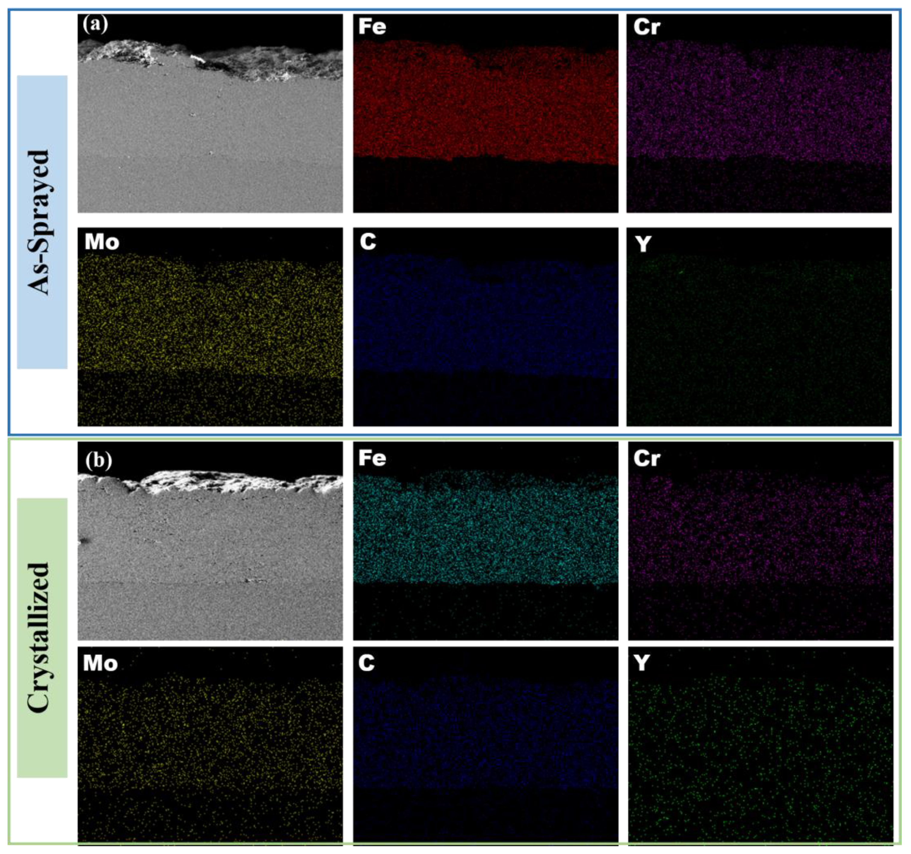
EDX analysis was performed to evaluate the elemental distribution throughout the amorphous and crystallized coatings, and the obtained EDX maps are illustrated in Figure 2. The EDS maps demonstrated the homogeneous distribution of all the alloying elements in both the amorphous and crystallized coatings.

3.2. Potentiodynamic Polarization Analysis

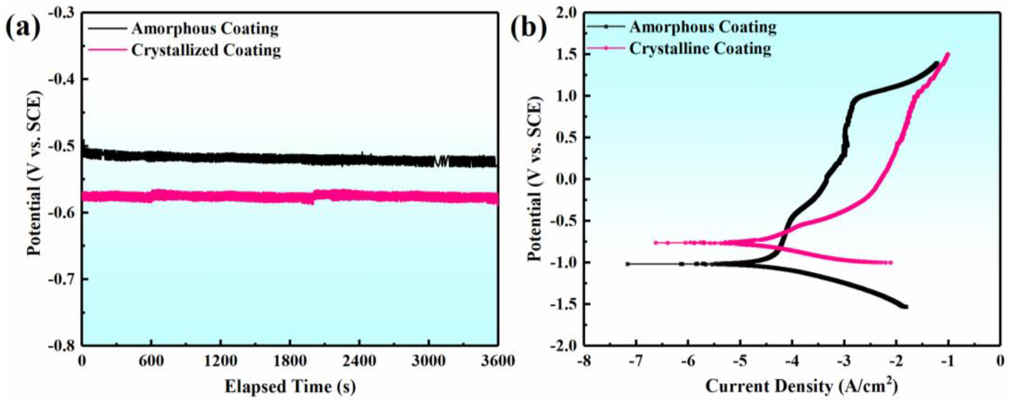
Corrosion is a very sensitive phenomenon that highly depends on microstructural variations. Therefore, the as-sprayed amorphous and heat-treated crystallized coatings were analyzed electrochemically. After the stabilization of the OCP, potentiodynamic polarization measurements were performed. The obtained PDP curves are plotted in Figure 3. The polarization behavior was evaluated in the potential range of −1 V to 1.5 V with respect to the open-circuit potential, with a scan rate of 1 mV/s. The kinetic parameters were calculated by a Tafel extrapolation method using NOVA 2.1 software, as illustrated in Table 1 According to the Butler–Volmer relation [33]:
i n e t = i o exp β a n F R T η a e x p   [ 1 β c n F R T η c ]
where β a and β c are the anodic and cathodic Tafel constants. η a and η c represent the anodic and cathodic polarizations of the surfaces during the Tafel extrapolation.
The results are presented in Table 1, showing the recorded end values for the Tafel fit of the polarization curves. The results of the as-sprayed coating revealed instantaneous passivation of the coating (see Figure 3a,b). However, thinning of the passive region was seen in the case of the crystallized coating, which indicates a decline in the corrosion resistance as some crystallized phases of carbides were developed during crystallization (see Figure 1b).
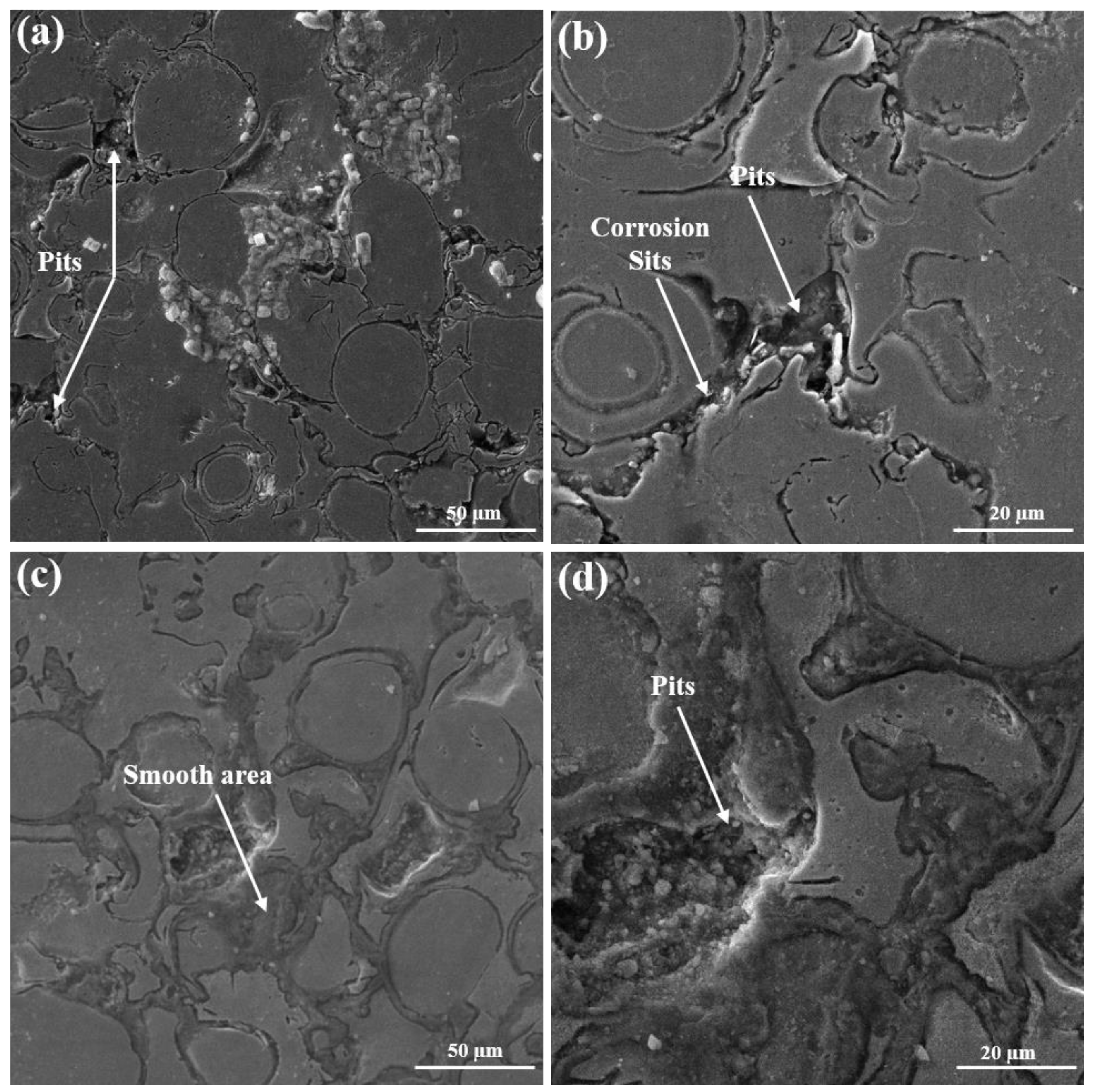
In the amorphous coating, the preferable sites for electrochemical attack are the inter-splat boundaries. The oxides of chromium and molybdenum, present in the passive film, provide a barrier for the corrosion active site [34]. Therefore, the obtained dense coating only provides minute sites (see Figure 4a,b) for corrosion attack; hence, the corrosion is not very aggressive.
The carbide formation after crystallization consumed protective oxide-forming elements (chromium and molybdenum). The strong depolarizing tendency of chloride ions, which are present in the electrolyte, promotes charge transfer at the oxide/electrolyte interface, disturbing the overall surficial charge distribution. Therefore, the produced heterogeneity provides a starting point for corrosion, which is evidenced by the SEM micrograph, as depicted in Figure 4c,d.
A straight line for the as-sprayed amorphous coating was observed (Figure 5a), presenting the involvement of Warburg impedance (W). Warburg impedance made the diffusion process nearly infinite [35]. This diffusion occurred at the inter-splat regions where the oxides were dissolved and provided a path for inner corrosion, i.e., pit formation (see Figure 4a,b). In contrast, the crystallized coating deviated from a straight line (as shown in the enlarged view of Figure 7c) and manifested semi-circular behavior, implying a unique time constant. Therefore, it is suggested that some sort of auxiliary reaction probably took place at the un-melted grain boundaries, where substantial precipitates of carbide are presented in Figure 4c,d. Considering the above analysis, two different circuits were proposed for both of the coatings. The common elements were the solution resistance (Rs), conduction ions resistance (Rp), and CPE-c representing the capacitance at the interface of the electrolyte and coating surface. In addition, the CPE-ct, as the capacitance for the double layer, was introduced for the crystallized coating, implying the capacitance between the pits formed and the coating/electrolyte, and Rct indicates charge transfer resistance. The equivalent models were fitted for EIS data using ZSim software v 3.20.
The results extracted from EIS data are shown in Table 2. It can be concluded from this tabulated data that the passive nature of the oxide layer immensely deteriorated because of the formation of crystalline regions during the thermal treatment. This is due to the increased number of defective sites, such as grain boundaries, and ultimately made it easier for the charge to transfer from the corroding agent, i.e., electrolyte to these sites. The manifold decrease in the CPE-c value discloses evidence of the above-mentioned mechanism [36]. The deterioration in the dielectric properties of the crystallized coating was predicted from the relaxation of the capacitive behavior, as shown in the Bodes plots in Figure 5b,c, close to an angle of 45°. However, a broader crest for the as-sprayed coating indicated the possible presence of more capacitive loops (see Figure 5a,b), which adds up to the corrosion resistance of the coating.

3.3. Tribological Properties

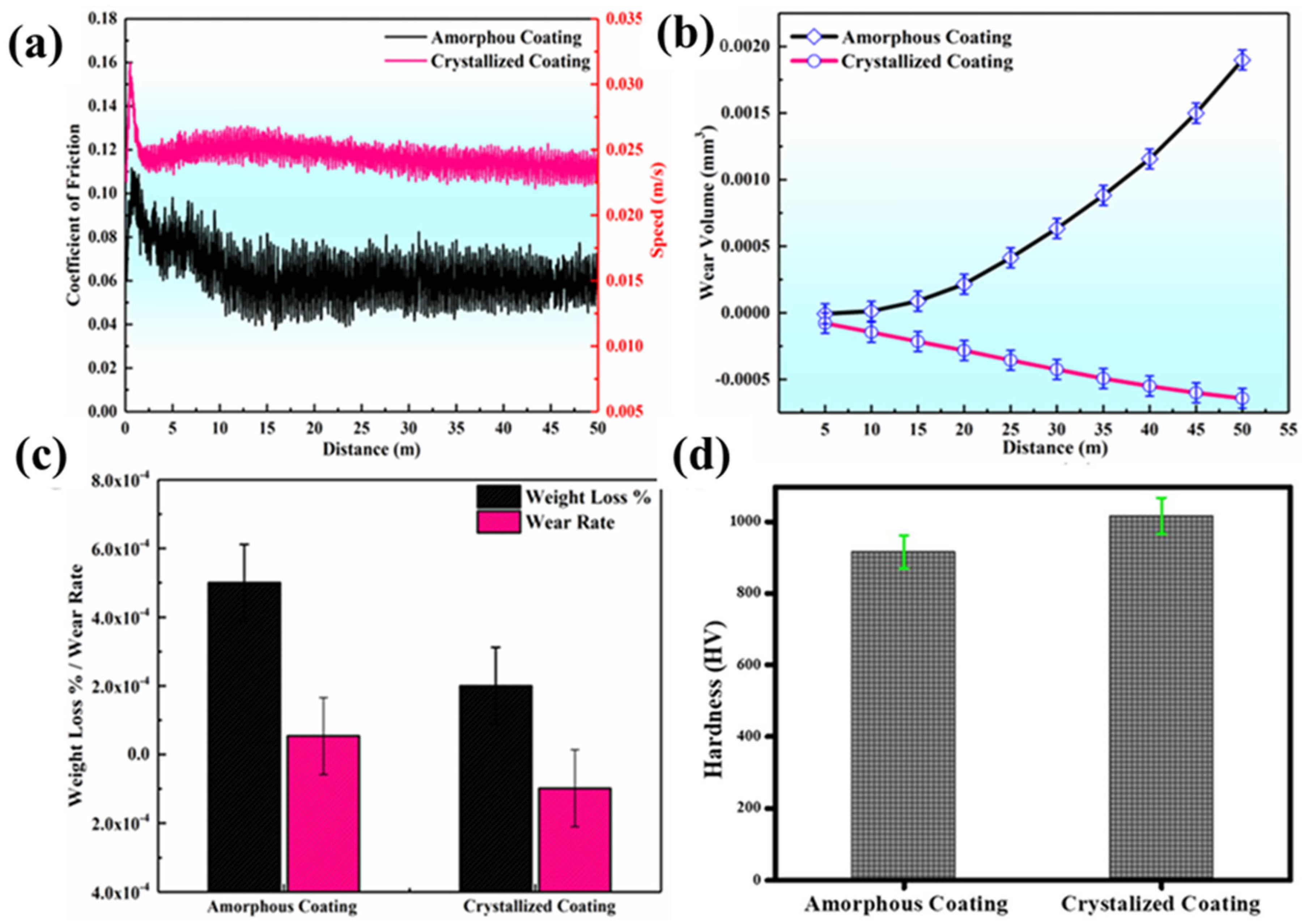
The results of the dry wear test, performed on a Microtest MT pin-on-disc Tribometer, are presented in Figure 6. It can be seen in Figure 6a that the amorphous coating exhibits a mean COF value of 0.19, whereas, for the crystallized coating, the COF decreased first from 0.1 to 0.05 and then stays around the mean value of 0.06.
The wear behavior of the as-sprayed amorphous coating can be explained on the basis of oxidation that took place during the in-flight of powder particles at the inter-splat regions. This is due to the high temperature of the semi-molten particle and the excess availability of oxygen used in the process. So, it can be concluded that the prevalent wear mechanism in the as-sprayed coatings was oxidation wear [23]. The uniform oxidized tribo-layer having a high hardness could delay the wear by evading the real contact between the frictional surface, hence improving the wear resistance [37]. However, this was not the case because of the oxidation at the inter-splat regions, and this heterogeneity and lamellar morphology of the splats weakened the metallurgical bonding in the case of the as-sprayed amorphous coating [38]. Moreover, in the case of dry-sliding, oxidation could be triggered by the rise in the surface temperature due to the high-frequency frictional force. The decrease in the COF and wear rate of a cold-sprayed Fe-amorphous coating has also been reported because of the high amorphous nature achieved. However, delamination and mild oxidation are also observed as the cause of wear [39,40]. The decrease in the COF of the crystallized coating (see Figure 6a) indicates improved wear resistance. The reason for the decrease in the COF was the precipitation of carbides [M7C3 and M23C6 (M = Fe, Cr, Mo)], which formed a harder phase and impinged the development of cracks and decreased the oxidation wear (a dominant wear mechanism in the as-sprayed coating) as the oxygen content was reduced at the inter-splats during crystallization.
Similarly, the polarity in the wear volume added a piece of evidence to the facts described above because the wear volume of the crystallized coating was decreased with the increase in the distance (see Figure 6b) as the harder carbides were exposed to the diamond indenter, while in the case of the as-sprayed amorphous coating, an increase in the wear volume was observed. The hardness of the crystallized coating was increased due to the carbide precipitations and thickening (see Figure 1d). Moreover, an increase in hardness, as shown in Figure 6d, with a decrease in the weight loss and wear rate for the crystallized coating was also evident, the same as described above, and there exists an inverse relation between hardness and weight loss i.e., Archard’s law [23,41,42]. The as-sprayed coating shows a decrease in hardness with an increase in the weight loss and wear rate.
For a thorough understanding of the wear mechanism, SEM of the wear tracks was performed. The SEM micrograph shown in Figure 7a,b for the as-sprayed amorphous coating shows less smooth areas, while the worn region shows the development of large micro-cracks. Moreover, the shielding nature of the oxide tribo-layer vanished when the oxidation became more severe, which made it very brittle, and eventually, it failed. Once this oxide tribo-layer fails, micro-cracks originate at the inter-splat regions and then propagate. It can be seen in Figure 7a,b that the volume of the smooth region is very low as compared to the worn one, as the epicenter of wear was the inter-splat region where oxygen was present. Also, the EDX of the worn surface shows the presence of high oxygen content.
On the contrary, the SEM micrographs of the crystallized coating indicate a larger smooth area along with delamination (a fatigue-related wear behavior). Cyclic sliding caused subsurface cracks due to the presence of a carbon under-layer, and the EDX of the delaminated region (Figure 7c,d) confirmed the presence of a higher percentage of carbon. The wearing of the crystallized coating surfaces produced flake-like wear debris. Hence, a transformation of the wear mechanism from oxidation to delamination was observed after crystallization. However, the overall wear resistance of the crystallized coating was improved as the mechanism of oxidation wear was suppressed. In addition, the carbide precipitates can bear the temperature rise and avoid further severe oxidation. Moreover, due to the carbide precipitation, as evident from the XRD in Figure 1b, the hardness of the coating is increased to about 10%, which decreased the wear volume of the crystallized coating (Figure 6d).

4. Conclusions

Detailed analysis conducted during this research work showed the formation of carbides [M7C3 and M23C6 (M = Fe, Cr, Mo)] in the AMC during crystallization, which fundamentally precipitated at the inter-splat regions of semi-molten particles where oxides were formed during the HVOF-coating procedure. A 57% increase in both the corrosion current density (from 4.95 μAcm−2 to 11.57 μAcm−2) and corrosion rate (from 4.28 mpy to 9.99 mpy) was observed after crystallization, attributed to the precipitation of the crystalline phases in the microstructure. The carbide formation consumed a large amount of Cr and Mo (the main elements of the passive film), which is detrimental to the homogeneity and composition of the protective film. In addition, EIS analysis revealed that this deterioration of the protective film provided more channels for the charge transfer and hence increased the corrosion rate of the crystallized coating. The crystallization also caused a 10% increase in the micro-Vickers hardness. Due to the increase in hardness, a 33% decrease in the COF (from 0.1 to 0.05) was also achieved, which was attributed to the hard carbide precipitation.

Author Contributions

Conceptualization, M.Y.; methodology, M.Y.; software, M.A.H.; validation, M.Y. and C.Z.; formal analysis, A.Q.A.; investigation, A.Q.A.; resources, M.Y. and C.Z.; data curation, M.A.-u.-R.; writing—original draft preparation, A.Q.A.; writing—review and editing, M.Y.; visualization, M.Y. and C.Z.; supervision, M.Y.; project administration, M.Y. and C.Z.; funding acquisition, M.Y. and C.Z. All authors have read and agreed to the published version of the manuscript.

Funding

This work was financially supported by the National Key R&D Program of China (No. 2021YFE0100600), Pakistan Science Foundation (Project Ref: PSF/CRP-18th Protocol (05)) and State Key Laboratory of Materials Processing and Die & Mould Technology, Huazhong University of Science and Technology Wuhan China (Project Reference: 2021-008).

Data Availability Statement

The data supporting the findings of this study are available on request from the corresponding author.

Acknowledgments

The authors are grateful for the analytical and technical assistance from their characterization labs of Institute of Space Technology Islamabad Pakistan.

Conflicts of Interest

The authors declare that they have no known competing financial interests or personal relationships that could have appeared to influence the work reported in this paper.

References

  1. Buchtík, M.; Hasoňová, M.; Horník, P.; Březina, M.; Doskočil, L.; Másilko, J.; Mrňa, L.; Filipenský, J.; Kuběna, I.; Fintová, S.; et al. Influence of laser remelting on the microstructure and corrosion behavior of HVOF-sprayed Fe-based coatings on magnesium alloy. Mater. Charact. 2022, 194, 112343. [Google Scholar] [CrossRef]
  2. Nayak, S.K.; Faridi, M.A.; Gopi, M.; Kumar, A.; Laha, T. Fe-based metallic glass composite coatings by HVOF spraying: Influence of Mo on phase evolution, wear and corrosion resistance. Mater. Charact. 2022, 191, 112149. [Google Scholar] [CrossRef]
  3. Meghwal, A.; Pinches, S.; King, H.J.; Schulz, C.; Stanford, N.; Hall, C.; Berndt, C.C.; Ang, A.S.M. Fe-based amorphous coating for high-temperature wear, marine and low pH environments. Materialia 2022, 25, 101549. [Google Scholar] [CrossRef]
  4. Varis, T.; Lagerbom, J.; Suhonen, T.; Raami, L.; Terho, S.; Laurila, J.; Peura, P.; Vuoristo, P. Effect of heat treatments on the wear resistance of HVAF and HVOF sprayed tool steel coatings. Surf. Coat. Technol. 2023, 462, 129508. [Google Scholar] [CrossRef]
  5. Inoue, A.; Kong, F.; Zhu, X.; Chen, J.; Men, H.; Botta, W.J. Development and industrialization of Zr- and Fe-based bulk metallic glasses and light metal-based metastable alloys. J. Alloys Compd. 2024, 979, 173546. [Google Scholar] [CrossRef]
  6. Al-Abboodi, H.; Fan, H.; Mhmood, I.A.; Al-Bahrani, M. The dry sliding wear rate of a Fe-based amorphous coating prepared on mild steel by HVOF thermal spraying. J. Mater. Res. Technol. 2022, 18, 1682–1691. [Google Scholar] [CrossRef]
  7. Ham, G.-S.; Cho, Y.-H.; Park, S.-Y.; Kim, C.P.; Ko, W.-S.; Lee, K.-A. Fabrication, microstructure, and wear properties of novel Fe–Cr–B–Nb–Mo metamorphic alloy coatings manufactured by the HVOF thermal spray process. Intermetallics 2023, 162, 108038. [Google Scholar] [CrossRef]
  8. Zhai, H.; Li, X.; Zhang, Y.; Li, W.; He, D.; Cheng, B.; Zhang, X.; Viktor, Z.; Seniuts, U. Non-isothermal crystallization behavioral analysis of detonation sprayed Fe-based amorphous coating. J. Mater. Res. Technol. 2023, 23, 6115–6126. [Google Scholar] [CrossRef]
  9. Liu, L.; Zhang, C. Fe-based amorphous coatings: Structures and properties. Thin Solid Film. 2014, 561, 70–86. [Google Scholar] [CrossRef]
  10. Zhai, F.; Pineda, E.; Duarte, M.J.; Crespo, D. Role of Nb in glass formation of Fe–Cr–Mo–C–B–Nb BMGs. J. Alloys Compd. 2014, 604, 157–163. [Google Scholar] [CrossRef]
  11. Xiao, M.; Jiang, F.; Guo, C.; Song, H.; Dong, T. Investigation on microstructure and mechanical properties of Fe-based amorphous coatings prepared via laser cladding assisted with ultrasonic vibration. Opt. Laser Technol. 2023, 162, 109294. [Google Scholar] [CrossRef]
  12. Meghwal, A.; Schulz, C.; Hall, C.; Vogli, E.; Berndt, C.C.; Ang, A.S.M. Microstructural, mechanical and high-temperature tribological performance of Fe-based fully amorphous and amorphous/crystalline coatings. Surf. Coat. Technol. 2023, 475, 130114. [Google Scholar] [CrossRef]
  13. Bhushan, B.; Banerjee, A.; Patel, S.N.; Banik, D.; Godbole, K.; Vishwanath, K.; Mandal, S.; Mondal, K. Electrochemical response and passivation affinity of Fe-based amorphous HVOF coatings prepared from pig iron on mild steel. Surf. Coat. Technol. 2023, 452, 129082. [Google Scholar] [CrossRef]
  14. Cui, S.; Zhai, H.; Tong, W.; Li, W.; Li, X.; Fan, X.; Xiong, D. Corrosion and tribo-corrosion behaviors of detonation sprayed Fe-based amorphous coating. Surf. Coat. Technol. 2024, 482, 130717. [Google Scholar] [CrossRef]
  15. Wang, H.; Cheng, Y.; Wan, Y.; Jeyaprakash, N.; Wang, Y.; Ma, K.; Yang, J. Influence of scanning speed on microstructure and corrosion resistance of Fe-based amorphous coatings by high-speed laser cladding. Surf. Coat. Technol. 2024, 479, 130449. [Google Scholar] [CrossRef]
  16. Zhu, P.-Y.; Feng, D.-Q.; Yasir, M.; Song, W.-L.; Hafeez, M.A.; Zhang, C.; Liu, L. Enhanced antifouling capability of PDMS/Cu2O-anchored Fe-based amorphous coatings. Surf. Coat. Technol. 2023, 475, 130192. [Google Scholar] [CrossRef]
  17. Wang, G.; Zhou, Z.; Zhang, K.; Wu, L.; Zhang, X.; Shi, X. Study on corrosion resistance of passive sealant to Fe-based amorphous coating at atomic-scale. Constr. Build. Mater. 2023, 408, 133661. [Google Scholar] [CrossRef]
  18. Iqbal, A.; Iqbal, A.; Moskal, G.; Yasir, M.; Al-Mansour, A.I.; Khan, M.A.; Alam, S.; Shahbaz, M.; Zia, A.; Ejaz, A. Long-Term Potentiodynamic Testing and Tribometric Properties of Amorphous Alloy Coatings under Saline Environment. Molecules 2022, 27, 1421. [Google Scholar] [CrossRef] [PubMed]
  19. Yang, Y.; Zhang, C.; Peng, Y.; Yu, Y.; Liu, L. Effects of crystallization on the corrosion resistance of Fe-based amorphous coatings. Corros. Sci. 2012, 59, 10–19. [Google Scholar] [CrossRef]
  20. Song, H.; Guo, C.; Li, J.; Jiang, F.; Diao, M.; Xiao, M.; Li, L.; Sun, Q. Study the influence of laser energy density on the amorphous content and properties of Fe-based amorphous coatings. Surf. Coat. Technol. 2024, 478, 130420. [Google Scholar] [CrossRef]
  21. Subbiah, R.; Arun, A.; Lakshmi, A.A.; Naga Sai Harika, A.; Ram, N.; Sateesh, N. Experimental Study of Wear Behaviour on Al-2014 Alloy Coated with Thermal Spray HVOF (High Velocity Oxy-Fuel) and Plasma Spray Process—A Review. Mater. Today Proc. 2019, 18, 5151–5157. [Google Scholar] [CrossRef]
  22. Liu, M.; Yu, Z.; Zhang, Y.; Wu, H.; Liao, H.; Deng, S. Prediction and analysis of high velocity oxy fuel (HVOF) sprayed coating using artificial neural network. Surf. Coat. Technol. 2019, 378, 124988. [Google Scholar] [CrossRef]
  23. Ma, H.R.; Li, J.W.; Jiao, J.; Chang, C.T.; Wang, G.; Shen, J.; Wang, X.M.; Li, R.W. Wear resistance of Fe-based amorphous coatings prepared by AC-HVAF and HVOF. Mater. Sci. Technol. 2017, 33, 65–71. [Google Scholar] [CrossRef]
  24. Sun, Y.J.; Yang, R.; Xie, L.; Li, Y.B.; Wang, S.L.; Li, H.X.; Wang, W.R.; Zhang, J.S. Interfacial bonding and corrosion behaviors of HVOF-sprayed Fe-based amorphous coating on 8090 Al-Li alloy. Surf. Coat. Technol. 2022, 436, 128316. [Google Scholar] [CrossRef]
  25. Sun, Y.J.; Yang, R.; Xie, L.; Wang, W.R.; Li, Y.B.; Wang, S.L.; Li, H.X.; Zhang, J.M.; Zhang, J.S. Interfacial bonding mechanism and properties of HVOF-sprayed Fe-based amorphous coatings on LA141 magnesium alloy substrate. Surf. Coat. Technol. 2021, 426, 127801. [Google Scholar] [CrossRef]
  26. Sweitzer, J.E.; Shiflet, G.J.; Scully, J.R. Localized corrosion of Al90Fe5Gd5 and Al87Ni8.7Y4.3 alloys in the amorphous, nanocrystalline and crystalline states: Resistance to micrometer-scale pit formation. Electrochim. Acta 2003, 48, 1223–1234. [Google Scholar] [CrossRef]
  27. Lucente, A.M.; Scully, J.R. Pitting of Al-Based Amorphous-Nanocrystalline Alloys with Solute-Lean Nanocrystals. Electrochem. Solid-State Lett. 2007, 10, C39. [Google Scholar] [CrossRef]
  28. Wang, Y.; Li, K.Y.; Scenini, F.; Jiao, J.; Qu, S.J.; Luo, Q.; Shen, J. The effect of residual stress on the electrochemical corrosion behavior of Fe-based amorphous coatings in chloride-containing solutions. Surf. Coat. Technol. 2016, 302, 27–38. [Google Scholar] [CrossRef]
  29. Yoo, Y.H.; Lee, S.H.; Kim, J.G.; Kim, J.S.; Lee, C. Effect of heat treatment on the corrosion resistance of Ni-based and Cu-based amorphous alloy coatings. J. Alloys Compd. 2008, 461, 304–311. [Google Scholar] [CrossRef]
  30. Zhou, Z.; Wang, L.; Wang, F.C.; Zhang, H.F.; Liu, Y.B.; Xu, S.H. Formation and corrosion behavior of Fe-based amorphous metallic coatings by HVOF thermal spraying. Surf. Coat. Technol. 2009, 204, 563–570. [Google Scholar] [CrossRef]
  31. Ha, H.M.; Miller, J.R.; Payer, J.H. Devitrification of Fe-Based Amorphous Metal SAM 1651 and the Effect of Heat-Treatment on Corrosion Behavior. J. Electrochem. Soc. 2009, 156, C246. [Google Scholar] [CrossRef]
  32. Conshohocken, W.J.W. Standard test method for wear testing with a pin-on-disk apparatus 1. Wear 2007, 5, 1–5. [Google Scholar]
  33. Inam, A.; Hafeez, M.A.; Atif, M.; Ishtiaq, M.; Hassan, M.H.; Hussain, T.; Mughal, M.S.; Raza, M.A.; Abbas, M.A.Q.; Ullah, I. Microstructural, Mechanical, and Electrochemical Properties of Quenched and Partitioned 3 wt% Mn Steel. Arab. J. Sci. Eng. 2021, 46, 417–423. [Google Scholar] [CrossRef]
  34. Wang, W.; Zhang, C.; Zhang, Z.-W.; Li, Y.-C.; Yasir, M.; Wang, H.-T.; Liu, L. Toughening Fe-based Amorphous Coatings by Reinforcement of Amorphous Carbon. Sci. Rep. 2017, 7, 4084. [Google Scholar] [CrossRef] [PubMed]
  35. Macdonald, J.R. Impedance spectroscopy. Ann. Biomed. Eng. 1992, 20, 289–305. [Google Scholar] [CrossRef] [PubMed]
  36. Yasir, M.; Zhang, C.; Wang, W.; Zhang, Z.-W.; Liu, L. Tribocorrosion Behavior of Fe-Based Amorphous Composite Coating Reinforced by Al2O3 in 3.5% NaCl Solution. J. Therm. Spray Technol. 2016, 25, 1554–1560. [Google Scholar] [CrossRef]
  37. Wang, W.; Zhang, C.; Xu, P.; Yasir, M.; Liu, L. Enhancement of oxidation and wear resistance of Fe-based amorphous coatings by surface modification of feedstock powders. Mater. Des. 2015, 73, 35–41. [Google Scholar] [CrossRef]
  38. Zhou, H.; Zhang, C.; Wang, W.; Yasir, M.; Liu, L. Microstructure and Mechanical Properties of Fe-based Amorphous Composite Coatings Reinforced by Stainless Steel Powders. J. Mater. Sci. Technol. 2015, 31, 43–47. [Google Scholar] [CrossRef]
  39. Henao, J.; Concustell, A.; Cano, I.G.; Cinca, N.; Dosta, S.; Guilemany, J.M. Influence of Cold Gas Spray process conditions on the microstructure of Fe-based amorphous coatings. J. Alloys Compd. 2015, 622, 995–999. [Google Scholar] [CrossRef]
  40. Yoon, S.; Kim, J.; Bae, G.; Kim, B.; Lee, C. Formation of coating and tribological behavior of kinetic sprayed Fe-based bulk metallic glass. J. Alloys Compd. 2011, 509, 347–353. [Google Scholar] [CrossRef]
  41. Abbas, A.; Huang, S.J.; Ballóková, B.; Sülleiová, K. Tribological effects of carbon nanotubes on magnesium alloy AZ31 and analyzing aging effects on CNTs/AZ31 composites fabricated by stir casting process. Tribol. Int. 2020, 142, 105982. [Google Scholar] [CrossRef]
  42. Lu, T.-t.; Hua, D.-p.; An, B.-L.; Hafeez, M.A.; Pan, J.; Chen, L.-X.; Lu, J.-Y.; Zhou, Q.; Zhang, C.; Liu, L. Improved anti-adhesive wear performance of rail/armature pair via interfacial energy modulation for electromagnetic launching applications. Scr. Mater. 2023, 236, 115677. [Google Scholar] [CrossRef]
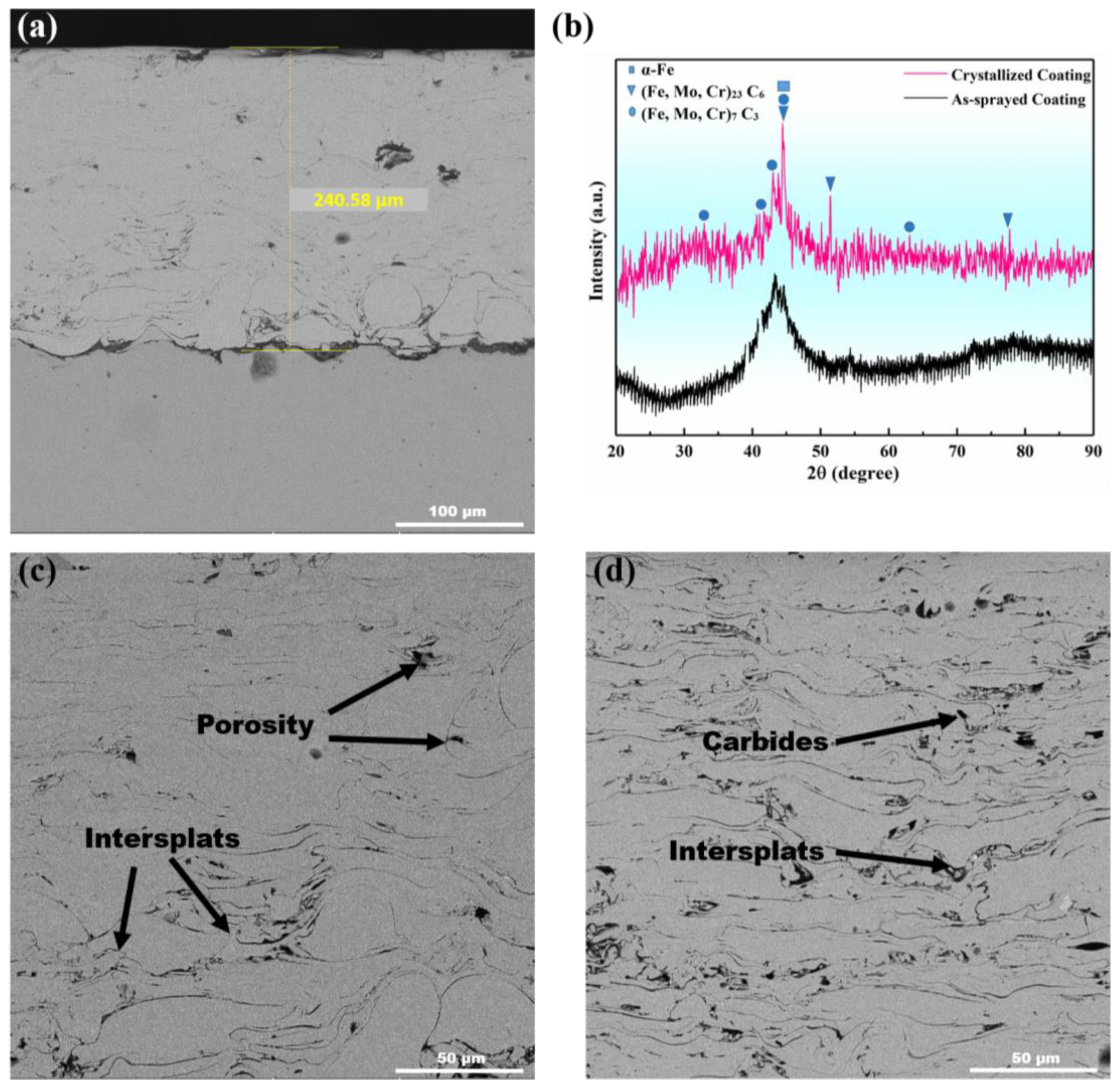
Figure 1. (a) SEM micrograph of the as-sprayed amorphous coating, (b) XRD plot of the as-sprayed amorphous and crystallized coating, (c) SEM morphology of the as-sprayed amorphous coating showing pores and inter-splats, and (d) SEM morphology of the crystallized coating.
Appliedchem 04 00017 g001
Figure 2. EDS maps of the (a) as-sprayed amorphous coating and (b) crystallized coating.
Appliedchem 04 00017 g002
Figure 3. (a) Open-circuit potential and (b) PDP curves of amorphous and crystallized coatings.
Appliedchem 04 00017 g003
Figure 4. Surface morphology of the (a,b) amorphous and (c,d) crystallized coatings after the corrosion test, showing pit formation and corrosion by products at the inter-splat regions.
Appliedchem 04 00017 g004
Figure 5. EIS curves of the amorphous and crystallized coatings: (a) Nyquist plot, (b) Bode plot of frequency vs. –phase, (c) Bode plot of frequency vs. |Z|, and (d) equivalent circuits used for data fitting of the EIS curves.
Appliedchem 04 00017 g005
Figure 6. (a) Coefficient of friction as a function of the sliding distance, (b) wear volume as a function of the distance covered, (c) comparison of % weight loss and wear rate, and (d) comparison of the hardness of the amorphous and crystalized coatings.
Appliedchem 04 00017 g006
Figure 7. SEM micrographs of the (a,b) amorphous coating after wear and its enlarged image, showing cracks generation and initiation under layer wear, and the (c,d) crystallized coating and its enlarged image, showing delamination.
Appliedchem 04 00017 g007
Table 1. PDP kinetic parameters of Fe-based amorphous and crystallized coatings.
CoatingsOCP (mV)Icorr (μAcm−2)Ecorr (mV)Corrosion Rat (mpy)
Amorphous−505.604.95−1006.04.28
Crystallized−586.411.57−768.799.99
Table 2. EIS parameters of Fe-based amorphous and crystallized coatings.
CoatingOCP
(mV)
Rs
(Ωcm2)
CPE-c
−1snm−2)
Rp
(Ωcm2)
WCPE-ct
−1sn cm−2)
Amorphous−505.64.318.01203.0
Crystallized−586.41.72.5 × 10465.11.1 × 106
Disclaimer/Publisher’s Note: The statements, opinions and data contained in all publications are solely those of the individual author(s) and contributor(s) and not of MDPI and/or the editor(s). MDPI and/or the editor(s) disclaim responsibility for any injury to people or property resulting from any ideas, methods, instructions or products referred to in the content.