Article

Experimental Studies on Low-Latency RIS Beam Tracking: Edge-Integrated and Visually Steered

1
School of Electrical and Electronic Engineering, Nanyang Technological University, Singapore 639798, Singapore
2
School of Physics and Electronic Information, Weifang University, Weifang 261061, China
*
Author to whom correspondence should be addressed.
These authors contributed equally to this work.
Network 2025, 5(3), 22; https://doi.org/10.3390/network5030022
Submission received: 5 April 2025 / Revised: 4 June 2025 / Accepted: 11 June 2025 / Published: 1 July 2025
(This article belongs to the Special Issue Advances in Wireless Communications and Networks)

Abstract

In this study, to address the problems of high feedback latency and redundant codebook traversal in traditional Reconfigurable Intelligent Surface (RIS) beam tracking systems, two novel experimental schemes are proposed: the Edge-Integrated RIS Control Mechanism (EIR-CM) and the Visually Steered RIS Control Mechanism (VSR-CM). The EIR-CM eliminates the feedback latency of the remote server and optimizes the local computation by integrating the RIS control system and the User Equipment (UE) into the same edge server to reduce the beam tuning time by 50%. The VSR-CM realizes beam tracking based on visual perception, and directly maps the UE position to the optimal RIS codebook with a response speed as low as milliseconds. Experimental results show that the EIR-CM reduces the RIS feedback latency to 1–2 s, and the VSR-CM can be further optimized to less than 0.5 s. The two mechanisms are applicable to 6G communications, smart transport, and drone networks, providing feasibility verification for low-latency and efficient RIS deployment.

1. Introduction

The Reconfigurable Intelligent Surface (RIS) is emerging as one of the key technologies for future 6G communications, millimeter-wave communications, and intelligent wireless networks due to its ability to dynamically regulate electromagnetic waves in wireless propagation environments. By dynamically adjusting the reflection phase, the RIS enables beam tracking to optimize signal coverage and enhance communication performance in Non-Line-of-Sight (NLOS) scenarios. In scenarios such as high-speed mobile communications, Unmanned Aerial Vehicle (UAV) networks, and Vehicle-to-Everything (V2X) communications, RIS beam tracking technology is particularly crucial as it can adapt to rapidly changing wireless channels in a passive manner, achieving low-energy, high-gain signal optimization [1,2,3,4,5,6].
In recent years, numerous RIS beam tracking methods have been proposed. In high-frequency communications (e.g., millimeter-wave and terahertz communications), the RIS enhances beamforming capabilities, improving beam tracking and beam training efficiency to meet the demands of high-mobility environments and multi-user scenarios [7,8,9]. Researchers have conducted in-depth studies on RIS-assisted beam training and tracking. In [10], a hierarchical codebook tracking scheme was investigated, where a coarse-grained codebook is first used for an initial scan to quickly determine the general direction, followed by a fine-grained codebook for precise adjustments. This approach reduces traversal time and enhances beam optimization efficiency. In [11], the problem of beam training in 6G space-air-ground integrated networks was studied, and a hash-mapping-based beam training scheme was proposed to improve the efficiency of RIS codebook selection. Additionally, the authors of [12] proposed a dynamic scatterer tracking scheme based on STAR-RIS (Simultaneous Transmission and Reflection RIS) technology, which reduces training overhead while enhancing system communication and sensing capabilities. In [13], beam training in terahertz (THz) communications was investigated, and a dual-layer true time-delay architecture was proposed to mitigate beam squint effects and improve beam tracking accuracy. Furthermore, the authors of [14] explored the application of RIS in Integrated Sensing and Communication (ISAC) systems, proposing a robust joint beamforming scheme to enhance the reliability of secure transmissions. In [15], a secure beamforming method combining RIS and Non-Orthogonal Multiple Access (NOMA) was studied to improve beam tracking and secure communication performance. In addition, the authors of [16] provides a joint mmWave sensing-and-communication framework that demonstrates how an IRS can simultaneously facilitate high-accuracy environmental sensing and data transmission. Furthermore, the authors of [17] proposes an active sensing scheme that significantly improves multiuser beam-tracking accuracy and robustness under dynamic channel conditions.
Despite significant theoretical advancements in RIS research, particularly in intelligent beamforming, optimized feedback mechanisms, and low-overhead CSI estimation, most studies remain in the theoretical simulation stage, with limited research on prototype-based RIS experiments [18,19,20,21]. The deployment of practical RIS devices is constrained not only by hardware computing capabilities but also by feedback mechanisms. Therefore, developing more feasible RIS control mechanisms is necessary to meet the requirements of real-world wireless communication environments [22,23,24,25]. Regarding prototype-based experimental research on RIS beam tracking, the authors of [26] studied the independent wave control characteristics of a 1-bit STAR-RIS. The study proposed a six-layer metal structure capable of independently controlling the transmission and reflection wave phases, with each unit achieving a 180° phase shift through p-i-n diodes. In [27], a 2-bit phase reconfigurable Intelligent Reflecting Surface (IRS) was proposed and experimentally validated in real-world environments. Outdoor far-field experiments demonstrated that IRS deployment significantly improved signal coverage in urban blind spots, with a signal gain increase of 8–12 dB compared to traditional metal reflectors. In [28], a 2-bit RIS prototype was investigated, focusing on fast-response 3D beam tracking and vortex beam generation to optimize dynamic wireless communications. Indoor experiments showed that 3D-focused beams could dynamically track moving targets, while outdoor experiments confirmed that the RIS possesses far-field multi-target beamforming capabilities. However, this system requires multiple feedback loops, the interaction between the UE and RIS remote servers, and a time synchronization mechanism between systems to complete the tracking process, leading to high tracking latency [29,30].
Existing prototype systems typically use remote servers to adjust RIS reflection modes. The UE must send feedback data, wait for remote computation, and then update the RIS state, relying on a time synchronization mechanism between the two systems to complete the tracking process. Consequently, the system response time is prolonged, making it unsuitable for low-latency RIS tracking applications. To address this issue, this paper proposes two novel RIS beam tracking prototype:
1.
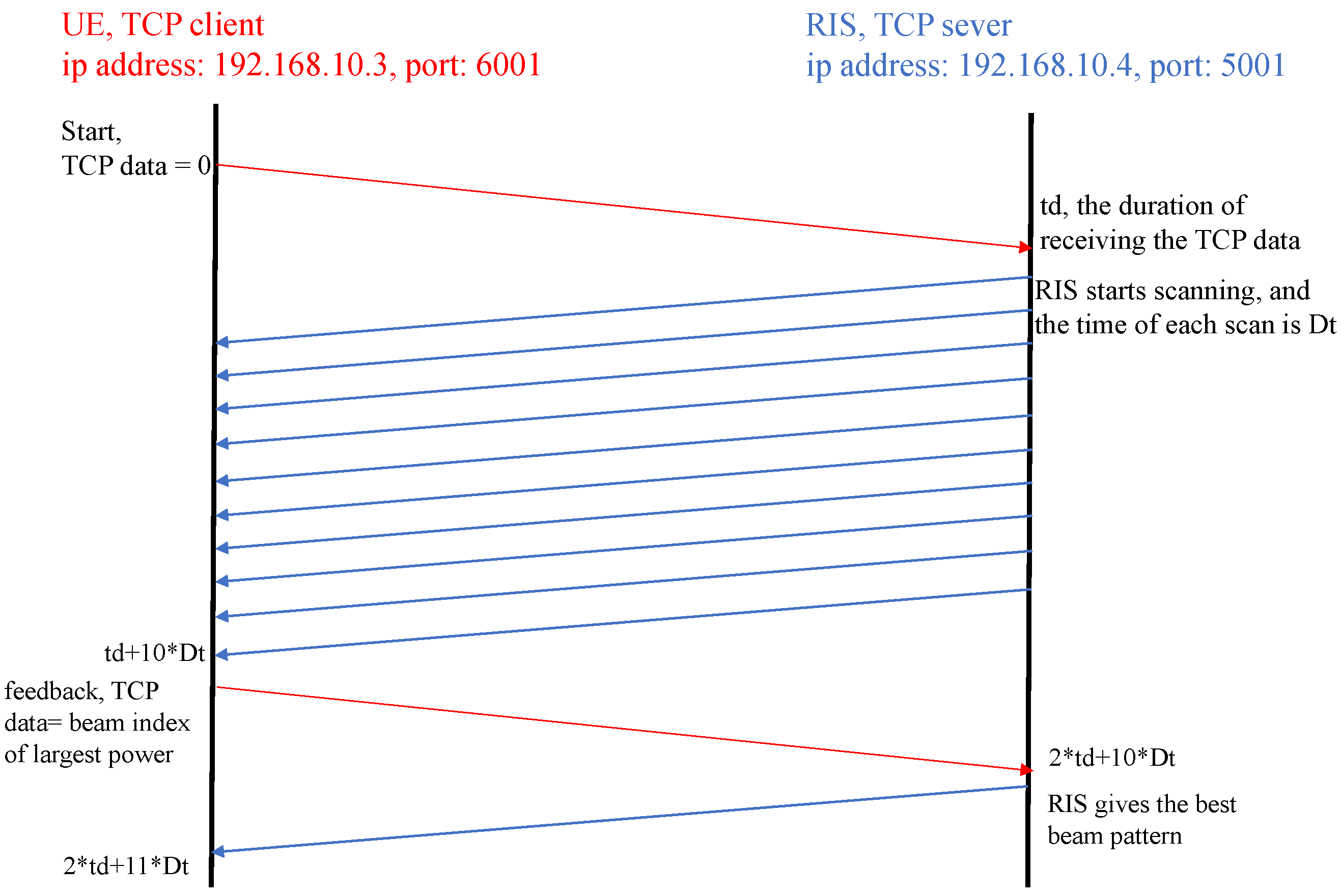
The Edge-Integrated RIS Control Mechanism (EIR-CM). This approach integrates the UE baseband signal processing and the RIS control system into the same edge server. It migrates the RIS feedback computation logic to a local computing unit, eliminating dependence on remote servers for codebook management. Within the Local Area Network (LAN), the UE directly controls the RIS reflection mode via TCP, bypassing remote server interactions. By adopting an integrated RIS control architecture, real-time CSI computation and RIS feedback optimization are performed on the local host, reducing beam adjustment latency by over 50% compared to traditional remote interaction schemes. This approach is suitable for low-latency, high-speed dynamic RIS tracking scenarios, particularly in applications such as smart buildings, industrial automation, and intelligent transportation, serving as a low-latency RIS control solution for 6G networks.
2.
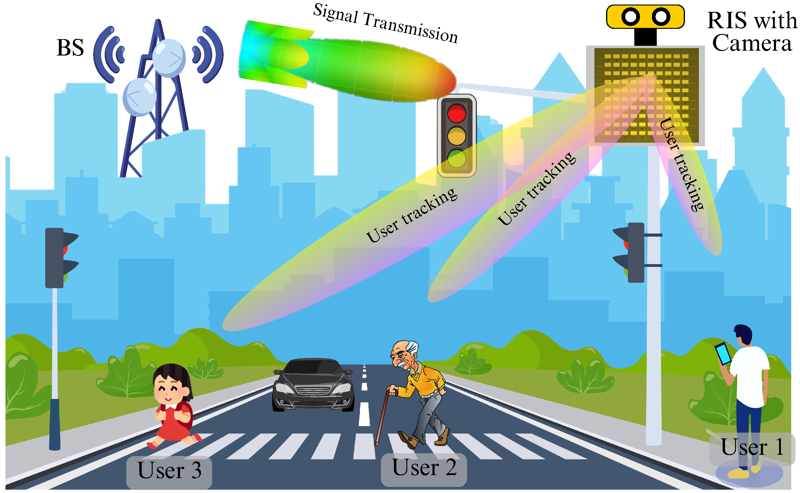
The Visually Steered RIS Control Mechanism (VSR-CM). This approach employs the YOLOv7 object detection algorithm [31] + depth camera (Intel RealSense D435i) for user detection, enabling real-time UE position recognition. Unlike traditional methods that traverse the entire codebook, this scheme directly maps the detected user position to the optimal RIS codebook via object detection, significantly accelerating beam adjustment. As a result, no feedback from the UE to the RIS control system is required, and RIS control is performed purely based on vision perception, reducing feedback communication overhead. This approach is particularly suitable for high-speed mobile users (such as drones, autonomous driving, and V2X vehicular networks) and enables millisecond-level dynamic RIS beam adjustments, improving tracking stability.

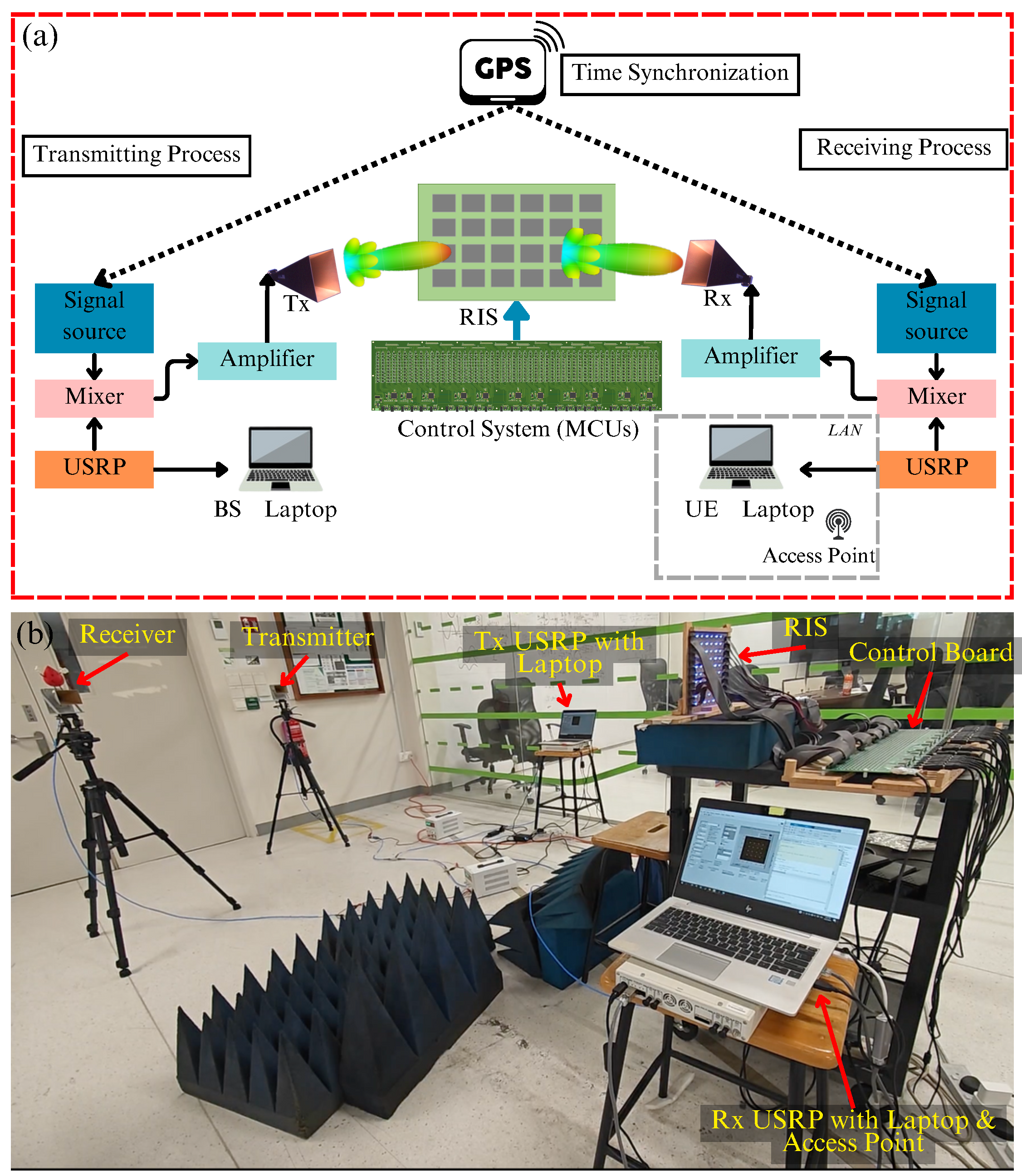
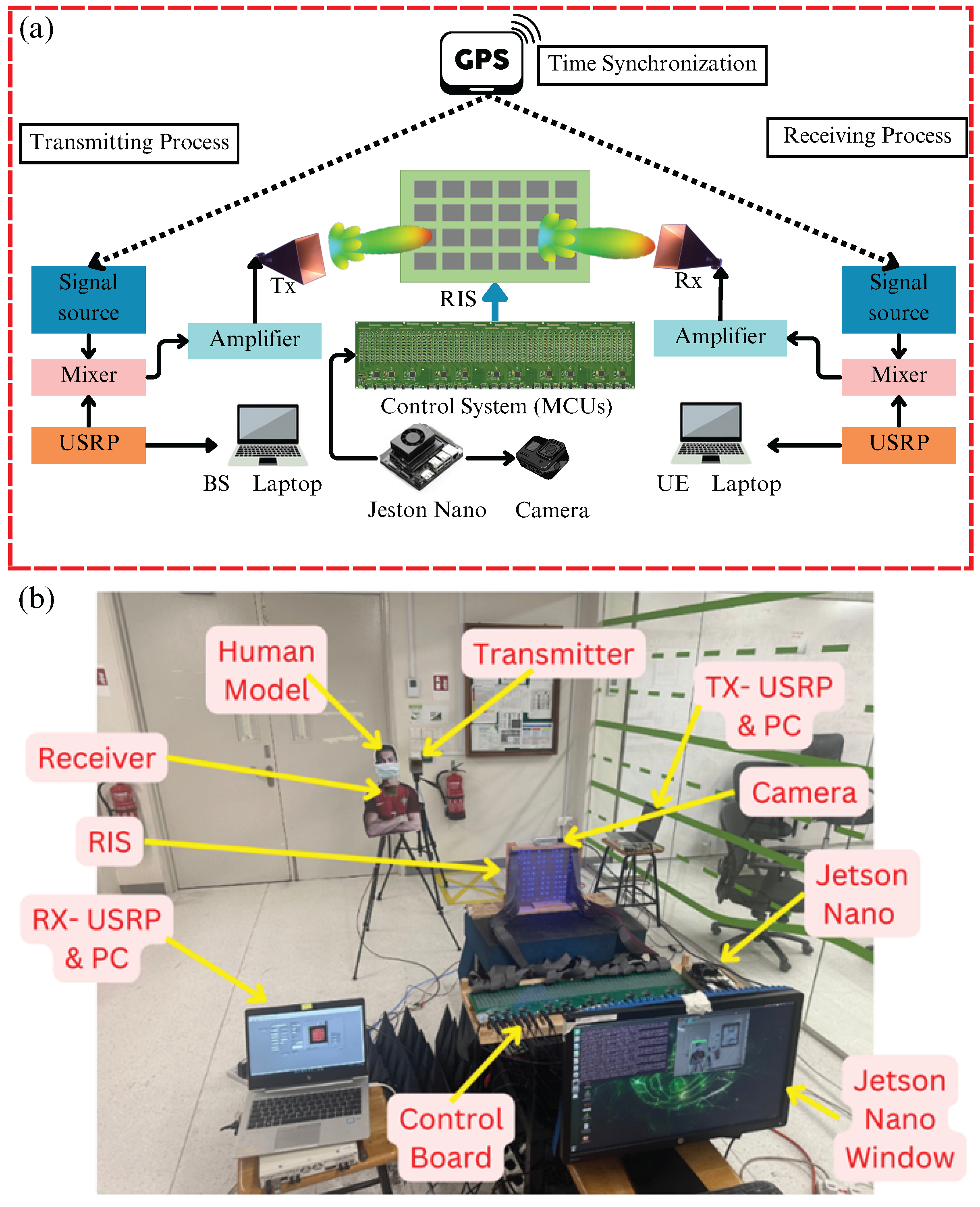
2. System Architecture

2.1. The Edge-Integrated RIS Control Mechanism

Figure 1 shows the typical application scenario of the EIR-CM. In order to overcome the high latency, low robustness, and complex time synchronization mechanism in the traditional RIS feedback system, this study proposes the integration of the UE baseband processing and RIS control modules into the same edge server. That is, the RIS control unit and UE measurement unit are integrated into the UE local computing unit and the LAN structure is redesigned. As the RIS and UE run in the same system environment, additional time synchronization mechanisms are no longer required, enabling real-time RIS feedback adjustment. A WiFi access point is linked to the outside of the system to assign an IP address to the RIS control system, ensuring that the RIS and the UE communicate by being on the same LAN. At the same time, the UE maintains a connection to the USRP to ensure that the base-band signal processing is synchronized with the feedback mechanism and is connected to the RIS control system via the LAN. Due to the high reliability of TCP transmission, the data exchange still uses TCP, but the RIS control unit and the UE measurement unit share the same host, so the data transmission path is extremely short, eliminating the additional latency associated with remote network communication. This architecture ensures that all feedback calculations are performed within the same host, significantly reducing data transfer overheads and improving the stability of the feedback system.
Figure 2 shows the time series analysis of the RIS feedback and Algorithm 1 is the corresponding beam tracking algorithm, further illustrating how the method reduces the feedback delay and improves system stability. When the UE device detects that the received signal power P r falls below the threshold g t , it stops demodulation and establishes a TCP connection with the RIS control system. The UE acts as a TCP client with one IP address of 192.168.10.3, while the RIS operates as a TCP server with another IP address of 192.168.10.4. The UE sends a TCP message with data = 0 to notify the RIS to enter beam scanning mode. Upon receiving the message, the RIS immediately starts scanning according to a predefined codebook, where each beam direction is scanned for a duration of D t = 80∼120 ms. Since the system allows the UE to control the RIS beam scanning method directly, it maintains simplicity and robustness. Compared to the traditional scanning duration of 150∼200 ms, this approach reduces scanning time and improves feedback efficiency.
Algorithm 1 The EIR-CM mode tracking algorithm
1:
Input: Receiving power p r , sensitivity threshold g t , transition time Δ t for each spot beam
2:
while true do
3:
   if  p r < g t  then
4:
       UE stops demodulating
5:
       UE and RIS control system establish a TCP connection
6:
       UE (as client) sends TCP data = 0, signaling RIS to begin scanning and measure p r on the UE side
7:
       for  BID = 0 to B max  do
8:
          RIS control system scans using the pre-defined codebook pattern (BID is the pattern index)
9:
          UE receives signal and calculates power u ( i ) on the UE side
10:
        Delay Δ t ms
11:
      end for
12:
      Compare and find the largest u ( i ) , denote it as p r
13:
       B max = maxIndex ( p r )    // index of the largest p r in the codebook
14:
      Feedback B max from UE to RIS
15:
       Beam B B max
16:
   end if
17:
end while
For instance, the RIS sequentially scans 10 sets of codebooks, and the UE computes and records the received power u i at each direction. The total scanning phase duration is 10 × D t . Once the scanning phase is completed, the UE determines the beam index B max corresponding to the maximum received power and transmits it to the RIS via TCP. The RIS then immediately switches to the optimal beam mode. Since the TCP feedback time t d is extremely short (3∼4  μ s), the system can rapidly adjust to the optimal beam mode, improving real-time performance. This optimized approach reduces the total feedback latency from 3∼4 s in conventional methods to 1∼2 s, achieving an improvement in efficiency of 50∼70% [28].

2.2. Visually Steered RIS Control Mechanism

Although the EIR-CM has significantly improved the system performance (by more than 50%), the system still suffers from some latency. This latency is mainly due to the double TCP feedback overhead: the UE needs to send feedback to the RIS to trigger beam scanning, and the RIS also needs to provide feedback acknowledgement. In addition, since the system has to traverse all the codebook beams to determine the optimal beam direction, this process further increases the response time of the system. To solve this problem, VSR-CM is proposed to utilize the YOLOv7 target detection model and the Intel RealSense D435i depth camera to achieve more efficient user tracking and beam steering. As shown in Figure 3, this scheme uses computer vision to detect the presence of a user and directly infer its position information to quickly determine the optimal beam direction without traversing all the codebooks or relying on the extra delay caused by TCP feedback. The YOLOv7 target detection model is used for real-time user detection and location determination, and an Intel RealSense D435i depth camera captures the user’s 3D coordinates. The user’s spatial coordinates are then quickly mapped to the optimal RIS reflection beam using a predefined codebook in the experimental environment. The optimal beam information is then sent directly to the RIS control system, eliminating the need to traverse all codebook beams.
In this study, a vision-based RIS beam dynamic tracking algorithm is proposed. This algorithm leverages the YOLOv7 object detection model and the Intel RealSense D435i depth camera to quickly identify the location of the UE and dynamically adjust the RIS reflection mode to optimize wireless signal coverage [32]. Algorithm 2 consists of four core steps: object detection, grid partitioning, position mapping, and mode control.
Algorithm 2 The VSR-CM mode tracking algorithm
1:
Configure YOLOv7 model and Intel RealSense D435i Camera: Enable RGB and depth streams.
2:
Initialize UART with the RIS control board.
3:
Load RIS reflection patterns from "Patterns.txt".
4:
last_grid_position = None % Tracks the historical position of the UE and does not re-config the RIS if the UE is at the same grid position
5:
While(1):
6:
   The YOLOv7 model start detect people. The model outputs the coordinates of bounding box: [ ( x 1 , y 1 ) , ( x 2 , y 2 ) ] and class
7:
   Divide the image into 8 horizontal grid cells: cell_width = frame_width/8, %cell_height = frame_height. We only treat the image space into 8 parts according to the horizontal area.
8:
   Calculate the bounding box center ( c x , c y ) % c x = ( x 1 + x 2 ) / 2 , c y = ( y 1 + y 2 ) / 2
9:
   Determine the grid column based on c x : column = int ( c x / cell _ width )
10:
   current_grid_position = (0,column) % Determine which grid area the user is in
11:
   If (current_grid_positionlast_grid_position) % Check if there is a move to a new cell
12:
      last_grid_position = current_grid_position % Update the last position
13:
      pattern_index = column % mapping each grid index directly to the codebook index
14:
      pattern = patterns[pattern_index] % Read the corresponding RIS pattern instructions from "Patterns.txt"
15:
      UART_write(pattern) % Send the pattern to the RIS control board via UART
16:
   End If
17:
End While
Algorithm description:
1.
Pre-processing stage: First, the system initializes the YOLOv7 target detection model, loads the pre-trained YOLOv7 model, and starts the RGB and depth data streams from the Intel RealSense D435i camera; the RGB images are used for target detection, while the depth information is used for the subsequent spatial coordinate calculation. In addition, the system initializes UART communication to establish a serial connection between the RIS control system and the FPGA control board for transmitting beam control commands. Finally, the system loads the RIS reflection codebook (Patterns.txt), which stores the RIS reflection patterns in different directions. The system will select the appropriate beam direction according to the detected user position.
2.
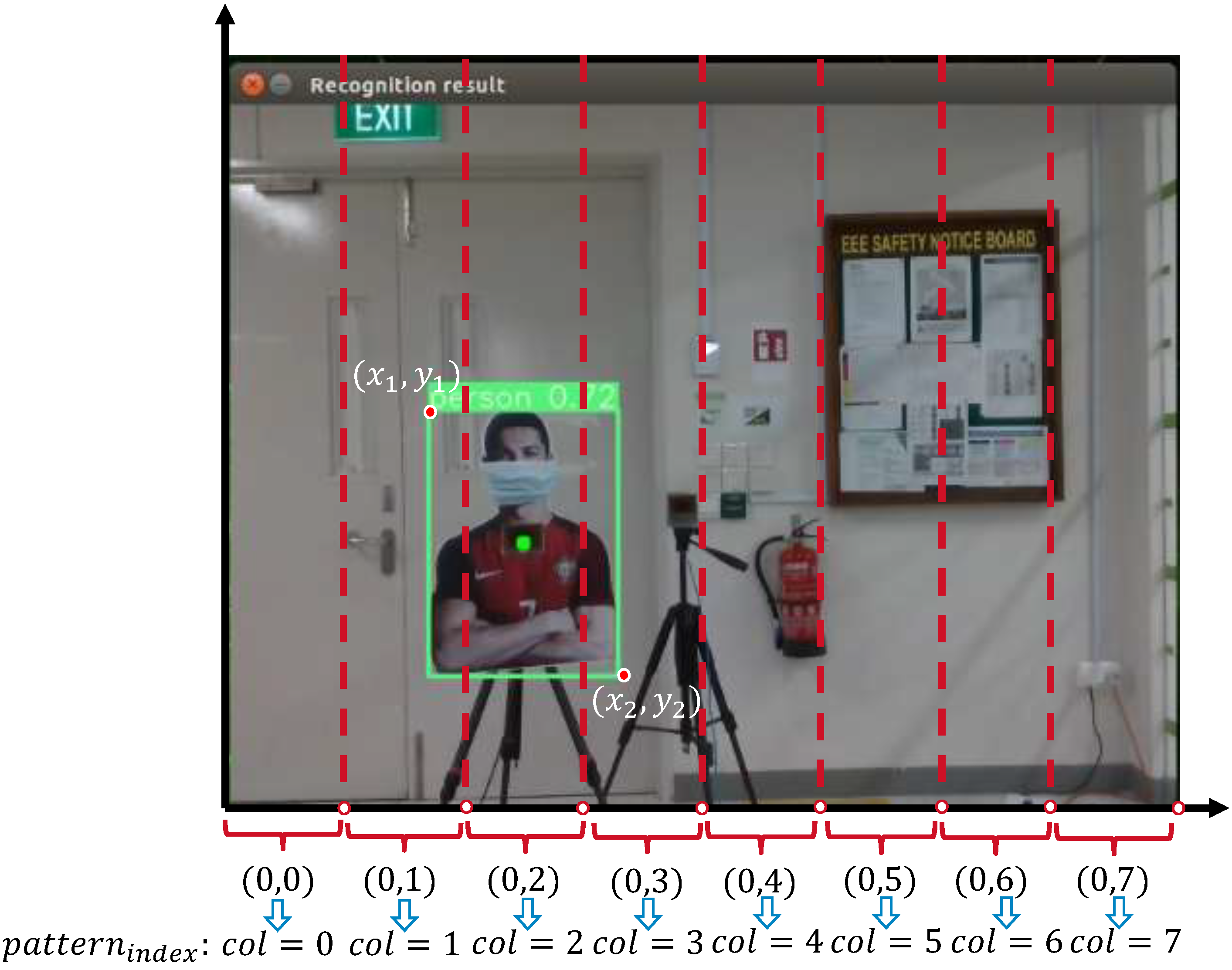
Object Detection and User Localization: The camera starts capturing environmental images, and the YOLOv7 model processes the input RGB image to output object detection results, including bounding box coordinates ( x 1 , y 1 ) , ( x 2 , y 2 ) , where ( x 1 , y 1 ) represents the top-left corner of the detected object, and ( x 2 , y 2 ) represents the bottom-right corner (as shown in Figure 4). YOLOv7 also classifies detected targets and provides a confidence score to ensure detection reliability. For RIS beam control, the system divides the image level into 8 grid cells (cells) and calculates the cell width:cell_width = frame_width/8.

3. Results

3.1. Demonstration of the Edge-Integrated RIS Control Mechanism

This experiment builds a complete RIS-assisted optimized wireless transmission system. The experimental setup includes a transmitter (TX), receiver (RX), RIS board, FPGA control system, USRP, etc. The overall system architecture is illustrated in Figure 5. In order to verify the hardware architecture of the RIS tracking system and the effectiveness of the dynamic beam tracking algorithm, this experiment is firstly conducted in a non-line-of-sight (NLOS) scenario to test whether the UE is able to successfully receive and demodulate the signal with the assistance of RIS reflection. The TX continuously transmits a 16-QAM modulated signal, which is reflected by the RIS and propagated to the RX. In the initial state, the RIS uses the default beam direction without active beam adjustment. As shown in Figure 6a, the constellation diagram of the receiver is clearly recognizable, which indicates that the UE successfully receives the signal even under NLOS conditions. This result verifies that the RIS can still achieve effective signal coverage under NLOS conditions with the preconfigured beam direction.
As shown in Figure 6b, when the UE moves, due to the non-NLOS condition in the experimental environment. The UE is no longer in the optimal coverage area of the current RIS beam, resulting in signal distortion. It can be observed from the constellation diagram that the modulation points become scattered and jittery. Since the received signal quality drops below the preset threshold, according to Algorithm 1 , the UE triggers the RIS to enter beam scanning mode in order to relocate the optimal reflection direction and restore the signal quality.
As shown in Figure 6c, after the RIS beam scanning and adjustment, the system finally selects the optimal reflection direction and directs the signal to the new position of the UE. The constellation diagram of the receiver appears clear and focused, indicating successful modulation recovery and BER reduction. The results validate the effectiveness of the system, proving that the RIS is able to dynamically optimize the signal coverage in real time, improve the signal quality, and ensure the stability of communication performance in NLOS scenarios.

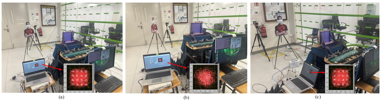
3.2. Demonstration of the Visually Steered RIS Control Mechanism

The whole system consists of a communication system module, a target detection and depth mapping module, and an RIS control module, which are responsible for communication signal transmission, user detection and coordinate calculation, and RIS beam adjustment, respectively, so as to realize vision-based RIS beam tracking. This scheme eliminates the feedback mechanism between the receiver and the RIS. YOLOv7 and Intel RealSense D435i are used in this experiment for real-time target detection to recognize the user’s position in the scene. The Intel RealSense D435i depth camera is responsible for capturing the RGB image and depth information, and calculating the user’s spatial coordinates ( X , Y , Z ) according to Algorithm 2 through the Grid Mapping mechanism to determine the user’s position in the environment. The complete system architecture is shown in Figure 7.
As shown in Figure 8a, the camera detects that the target user appears on the left side of the frame and uses the YOLOv7 target detection model to identify its exact location and outputs the bounding box coordinates and confidence score of the detected user. Subsequently, the RIS control system determines the spatial region of the user based on the detected position and selects the corresponding RIS codebook entry to adjust the RIS reflected beam direction, thus ensuring that the signal is enhanced towards the target user. At this point, the receiver obtains a strong signal. The experimental results show that the constellation diagram is clear and the symbol clusters are concentrated, indicating good signal quality and low BER.
As shown in Figure 8b, when the target user is completely out of the camera’s field of view or when absorbing material is used to block the RIS reflective path, the system is unable to detect a valid target. As a result, the RIS is unable to adjust the beam accordingly, resulting in a signal that does not effectively reach the receiver. In this case, the receiver’s constellation map is severely distorted. This further validates the critical role played by visual-based perception in the RIS control process.
When the target user moves to the right within the camera’s field of view, the system continuously detects the user’s position and adjusts the RIS reflective beam accordingly to ensure stable signal transmission to the receiver. The experimental results are shown in Figure 8c. From the constellation diagram of the receiver, it can be observed that, despite the user’s movement, the received signal still maintains good quality, with clear and concentrated symbol clusters and a low bit error rate (BER). This indicates that the RIS control system is able to effectively track the user’s movement and optimize the signal reflection path in real time.

4. Discussion

Table 1 presents a comparison of tracking latency among the three approaches: the traditional scheme has a feedback delay of up to 3–4 s, needs to interact with the remote server via UE for the RIS feedback mechanism, and relies on cross-device time synchronization. The EIR-CM architecture proposed in this paper reduces the delay to 1–2 s by relocating the RIS feedback computation logic to the local computation unit and eliminating the need for cross-device synchronization, while the VSR-CM architecture selects the optimal codebook based on the visual perception without feedback and with a delay of less than 0.5 s. Obviously, the two methods proposed in this paper can provide more stable real-time communication links in the application scenarios with high dynamics and the need for accurate and fast beam tracing.

5. Conclusions

This study focuses on optimizing beam tracking for Reconfigurable Intelligent Surfaces. To address the system latency issues caused by multiple TCP feedback exchanges and exhaustive codebook traversal in traditional RIS systems, two optimization mechanisms were proposed and implemented. The proposed EIR-CM and VSR-CM architectures provide two complementary approaches for future 6G wireless networks with an integrated RIS: The EIR-CM provides a practical framework for real-world RIS deployment by reducing control latency and enabling decentralized RIS management. The VSR-CM eliminates the need for traditional CSI feedback, providing a fast, AI-driven approach to dynamic beam tracking and user-centric RIS optimization. These architectures reduce network signaling overhead and improve spectral and energy efficiency in dense urban environments. They enable multi-RIS co-optimization, leveraging edge computing and AI-based visual sensing to dynamically tune multiple RIS elements, and facilitate seamless integration of the RIS with next-generation wireless infrastructures for V2X, IoT, drone networks, and 6G ultra-reliable low-latency communications applications.

Author Contributions

Conceptualization, Z.W. and Y.N.; methodology, Z.W. and Y.N.; software, Z.W. and Y.N.; validation, Z.W. and Y.N.; writing—original draft preparation, Z.W.; writing—review and editing, Y.N. All authors have read and agreed to the published version of the manuscript.

Funding

This research received no external funding.

Data Availability Statement

The original contributions presented in this study are included in the article. Further inquiries can be directed to the corresponding author.

Acknowledgments

The authors are grateful to Afkar Mohamed Ismail and Yufei Zhao from Nanyang Technological University for their valuable discussions and support throughout this work.

Conflicts of Interest

The authors declare that there are no conflicts of interest.

List of Acronyms

AcronymDefinition
RISReconfigurable Intelligent Surface
UEUser Equipment
EIR-CMEdge-Integrated RIS Control Mechanism
VSR-CMVisually Steered RIS Control Mechanism
mmWaveMillimeter–Wave
LoS/NLoSLine-of-Sight/Non-Line-of-Sight
LANLocal Area Network
V2XVehicle-to-Everything
UAVUnmanned Aerial Vehicle
TCP/IPTransmission Control Protocol/Internet Protocol
FPGAField-Programmable Gate Array
CSIChannel State Information
YOLOv7You Only Look Once version 7 (real-time object detector)
UARTUniversal Asynchronous Receiver/Transmitter

References

  1. Zhao, Y.; Guan, Y.L.; Ismail, A.M.; Ju, G.; Lin, D.; Lu, Y.; Yuen, C. Holographic-inspired meta-surfaces exploiting vortex beams for low-interference multipair IoT communications: From theory to prototype. IEEE Internet Things J. 2024, 11, 12660–12675. [Google Scholar] [CrossRef]
  2. Xu, J.; Xu, W.; Yuen, C. On performance of distributed RIS-aided communication in random networks. IEEE Trans. Wirel. Commun. 2024, 23, 18254–18270. [Google Scholar] [CrossRef]
  3. Zhao, Y.; Wang, Z.; Lu, Y.; Guan, Y.L. Multimode OAM convergent transmission with co-divergent angle tailored by airy wavefront. IEEE Trans. Antennas Propag. 2023, 71, 5256–5265. [Google Scholar] [CrossRef]
  4. Chen, M.; Chen, R.; Zhao, Y.; Yang, Z.; Guan, Y.L. Index-modulation OAM detectors resistant to beam misalignment. IEEE Trans. Veh. Technol. 2023, 73, 2836–2841. [Google Scholar] [CrossRef]
  5. Zhao, Y.; Zhang, C. Compound angular lens for radio orbital angular momentum coaxial separation and convergence. IEEE Antennas Wirel. Propag. Lett. 2019, 18, 2160–2164. [Google Scholar] [CrossRef]
  6. Zhao, Y.; Zhang, C. Distributed antennas scheme for orbital angular momentum long-distance transmission. IEEE Antennas Wirel. Propag. Lett. 2019, 19, 332–336. [Google Scholar] [CrossRef]
  7. Yang, Z.; Ge, Y.; Zhao, Y.; Fang, Y.; Guan, Y.L. Protograph LDPC code and shaped index modulation design for multi-mode OAM systems. IEEE Trans. Commun. 2024, 72, 5162–5178. [Google Scholar] [CrossRef]
  8. Zhao, Y.; Ma, X.; Guan, Y.L.; Liu, Y.; Ismail, A.M.; Liu, X.; Yeo, S.Y.; Yuen, C. Near-orthogonal overlay communications in LoS channel enabled by novel OAM beams without central energy voids: An experimental study. IEEE Internet Things J. 2024, 11, 39697–39708. [Google Scholar] [CrossRef]
  9. Zhao, Y.; Guan, Y.L.; Chen, D.; Ismail, A.M.; Ma, X.; Liu, X. Exploring RCS diversity with novel OAM beams without energy void: An experimental study. IEEE Trans. Veh. Technol. 2024, 74, 8321–8326. [Google Scholar] [CrossRef]
  10. Wang, J.; Tang, W.; Jin, S.; Wen, C.-K.; Li, X.; Hou, X. Hierarchical codebook-based beam training for RIS-assisted mmWave communication systems. IEEE Trans. Commun. 2024, 71, 3650–3662. [Google Scholar] [CrossRef]
  11. Xu, Y.; Huang, C.; Wei, L.; Yang, Z.; Hammadi, A.A.; Yang, J.; Zhang, Z.; Yuen, C.; Debbah, M. Hashing beam training for integrated ground-air-space wireless networks. IEEE J. Sel. Areas Commun. 2024, 42, 3477–3489. [Google Scholar] [CrossRef]
  12. Li, M.; Zhang, S.; Ge, Y.; Yuen, C. STAR-RIS aided dynamic scatterers tracking for integrated sensing and communications. IEEE Trans. Veh. Technol. 2025, 74, 7760–7773. [Google Scholar] [CrossRef]
  13. Sun, G.; Yan, W.; Hao, W.; Huang, C.; Yuen, C. Beamforming design for the distributed RISs-aided THz communications with double-layer true time delays. IEEE Trans. Veh. Technol. 2025, 73, 3886–3900. [Google Scholar] [CrossRef]
  14. Jiang, C.; Zhang, C.; Huang, C.; Ge, J.; Niyato, D.; Yuen, C. RIS-assisted ISAC systems for robust secure transmission with imperfect sense estimation. IEEE Trans. Wirel. Commun. 2025, 24, 3979–3992. [Google Scholar] [CrossRef]
  15. Jiang, C.; Zhang, C.; Huang, C.; Ge, J.; Debbah, M.; Yuen, C. Exploiting RIS in secure beamforming design for NOMA-assisted integrated sensing and communication. IEEE Internet Things J. 2024, 11, 28123–28136. [Google Scholar] [CrossRef]
  16. Zhu, Z.; Li, Z.; Chu, Z.; Guan, Y.; Wu, Q.; Xiao, P.; Renzo, M.D.; Lee, I. Intelligent Reflecting Surface Assisted mmWave Integrated Sensing and Communication Systems. IEEE Internet Things J. 2024, 11, 29427–29437. [Google Scholar] [CrossRef]
  17. Han, H.; Jiang, T.; Yu, W. Active Sensing for Multiuser Beam Tracking With Reconfigurable Intelligent Surface. IEEE Trans. Wirel. Commun. 2025, 24, 540–554. [Google Scholar] [CrossRef]
  18. Zhang, C.; Zhao, Y. High precision deep sea geomagnetic data sampling and recovery with three-dimensional compressive sensing. IEICE Trans. Fundam. 2017, E100-A, 13172–13188. [Google Scholar] [CrossRef]
  19. Zhang, C.; Zhao, Y.; Zhang, Y.; Li, F.; Jiang, S. Position aided open-loop passive magnetic MIMO transmission. IET Commun. 2017, 11, 13172–13188. [Google Scholar] [CrossRef]
  20. Lin, D.; Wan, J.; Wang, J.; Kong, L.; Zhao, Y.; Guan, Y.L. A novel topology-scale-adaptive and energy-efficient clustering scheme for energy sustainable large-scale SWIPT-enabled WSNs. IEEE Trans. Mob. Comput. 2024, 23, 13172–13188. [Google Scholar] [CrossRef]
  21. Lin, D.; Zhao, J.; Yu, F.; Min, W.; Zhao, Y.; Guan, Y.L. A novel high-precision and low-latency abandoned object detection method under the hybrid cloud-fog computing architecture. IEEE Internet Things J. 2024, 11, 40448–40463. [Google Scholar] [CrossRef]
  22. Li, Y.; Zhao, Y.; Yuen, C.; Guan, Y.L.; Shen, Z. Enhanced bandwidth and continuous phase modulation in a novel varactor-based RIS design. In Proceedings of the 2024 IEEE International Symposium on Antennas and Propagation and INC/USNC-URSI Radio Science Meeting (AP-S/INC-USNC-URSI), Firenze, Italy, 14–19 July 2024. [Google Scholar]
  23. Feng, X.; Zhao, Z.; Zhao, Y.; Zhao, Z.; Meng, L.; Guan, Y.L. OFDM-based waveform design for MIMO DFRC systems with reduced range sidelobes: A majorization-minimization approach. IEEE Trans. Veh. Technol. 2024, 74, 4582–4595. [Google Scholar] [CrossRef]
  24. Zhao, Y.; Zhang, C. Orbital angular momentum beamforming for index modulation with partial arc reception. Electron. Lett. 2019, 55, 1271–1273. [Google Scholar] [CrossRef]
  25. Zhang, C.; Zhao, Y. Orbital angular momentum nondegenerate index mapping for long distance transmission. IEEE Trans. Wirel. Commun. 2019, 18, 1271–1273. [Google Scholar] [CrossRef]
  26. Hong, Y.; Zhao, Y.; Yuen, C.; Qing, X. A STAR-RIS with independent 1-bit wave control. In Proceedings of the 2024 IEEE International Symposium on Antennas and Propagation and INC/USNC-URSI Radio Science Meeting (AP-S/INC-USNC-URSI), Firenze, Italy, 14–19 July 2024. [Google Scholar]
  27. Zhao, Y.; Guan, Y.L.; Yuen, C.; Liu, X.; Ismail, A.M.; Ge, Y. Advanced artificial Doppler shift manipulation with rotational vortex beams in space-time digital-coding RIS system: A practical approach. In Proceedings of the 2024 IEEE VTS Asia Pacific Wireless Communications Symposium (APWCS), Singapore, 21–23 August 2024. [Google Scholar]
  28. Zhao, Y.; Feng, Y.; Ismail, A.M.; Wang, Z.; Guan, Y.L.; Guo, Y.; Yuen, C. 2-bit RIS prototyping enhancing rapid-response space-time wavefront manipulation for wireless communication: Experimental studies. IEEE Open J. Commun. Soc. 2024, 5, 4885–4901. [Google Scholar] [CrossRef]
  29. Zhao, Y.; Ismail, A.M.; Ju, G.; Wang, Z.; Liu, Y.; Guan, Y.L. 2-bit Intelligent Reflection Surface Enhances Urban Wireless Communications: An Experimental Study. In Proceedings of the 2024 IEEE International Workshop on Antenna Technology (iWAT), Sendai, Japan, 15–18 April 2024. [Google Scholar]
  30. Zhao, Y.; Ma, X.; Wang, Z.; Liu, Y.; Yuen, C.; Guan, Y.L. Enhancing Urban Mobile Communications with Dynamic 3D Beam Tracking: A 2-Bit Phase-Quantized Adaptive RIS Approach. In Proceedings of the 2024 IEEE 35th International Symposium on Personal, Indoor and Mobile Radio Communications (PIMRC), Valencia, Spain, 2–5 September 2024. [Google Scholar]
  31. Wang, C.Y.; Bochkovskiy, A.; Liao, H.Y.M. YOLOv7: Trainable bag-of-freebies sets new state-of-the-art for real-time object detectors. arXiv 2024, arXiv:2207.02696. [Google Scholar]
  32. Zhang, C.; Jiang, X.; Zhao, Y. Efficient instantaneous channel propagation modeling for aeronautical communications systems with compressed sensing. IEEE Trans. Antennas Propag. 2021, 70, 1211–1220. [Google Scholar] [CrossRef]
Figure 1. Edge-integrated RIS control mechanism application scenarios.
Network 05 00022 g001
Figure 2. An RIS feedback timing diagram with EIR-CM architecture.
Network 05 00022 g002
Figure 3. VSR-CM mode application scenarios.
Network 05 00022 g003
Figure 4. Grid mapping and pattern indexing for RIS control.
Network 05 00022 g004
Figure 5. Experimental setup of the EIR-CM system. (a) System diagram illustrating the signal flow, RIS placement, and GPS-based synchronization, etc. (b) Photo of the real experimental environment, showing the transmitter, receiver, RIS, control board, and USRP devices, etc.
Network 05 00022 g005
Figure 6. Experimental results with the EIR-CM system. (a) Initial State: A preconfigured RIS beam in NLOS. (b) UE Movement: Signal distortion due to a mismatched beam. (c) Beam Adjustment: Optimized RIS reflection for signal recovery.
Network 05 00022 g006
Figure 7. Experimental setup of the VSR-CM System. (a) System diagram of the VSR-CM architecture, showing the integration of the Jetson Nano and camera for visual sensing and RIS control, etc. (b) Photo of the experimental environment, illustrating the transmitter, receiver, RIS, Jetson Nano window, control board, and human target model, etc.
Network 05 00022 g007
Figure 8. Experimental results with the VSR-CM system. (a) RIS beam adjustment for target user on the left side of camera. (b) Signal distortion due to user absence or blocked by wave-absorbing materials. (c) Continuous RIS beam tracking for user movement to the right side of the camera.
Network 05 00022 g008
Table 1. Comparison of tracking performance across different RIS architectures.
Tracking SchemeTraditional Multi-Host Scheme [28]Edge-Integrated RIS Control MechanismVisually Steered RIS Control Mechanism
Tracking Latency3–4 s1–2 s<0.5 s
SynchronizationRequiredNo RequiredNo Required
FeedbackRequiredRequiredNo Required
Codebook TraversalTraverse AllTraverse AllDirectly Select Target Codebook
System ComplexityMulti-HostIntegrated HostSingle Host + Depth Camera
Disclaimer/Publisher’s Note: The statements, opinions and data contained in all publications are solely those of the individual author(s) and contributor(s) and not of MDPI and/or the editor(s). MDPI and/or the editor(s) disclaim responsibility for any injury to people or property resulting from any ideas, methods, instructions or products referred to in the content.

