3.1. Background on Polar Codes
Let be a binary-input discrete memoryless channel (B-DMC) with input and output alphabets and (the set of real numbers), respectively. The transition probability of the channel is denoted by , where . Let the subvector of be denoted by . If , then is the null vector.
There are two parameters that indicate the channel quality for polar codes: the symmetric capacity
and the Bhattacharyya parameter
. These are defined in [
23] as follows:
where the logarithm is taken with a basis of 2. The symmetric capacity
is the highest rate for reliable communication with equal input probabilities, and the Bhattacharyya parameter
is an upper bound to the error probability under ML decoding when transmitting over W. It was shown in [
23] that for any B-DMC, the following two inequalities hold:
Based on (
17) and (
18),
iff
, which indicates that the channel is reliable.
Polar codes exploit the channel polarization phenomenon. In channel polarization,
N independent copies of a B-DMC employing channel combining and channel splitting are transformed into
N synthesized bit channels
, where
denotes the
i-th such synthesized channel. As
N tends to infinity, the symmetric capacity
tends towards 0 or 1; hence, it is polarized. The transition probability of the
ith bit channel
is as follows [
23]:
For an polar code, the information bits are arranged to be located at the K most reliable bit locations and are transmitted over the best K bit channels. The other bits are called frozen bits, and their values are known to the decoder. Frozen bits do not carry information and are set to fixed values. In this work, all frozen bits are set to 0. The process of selecting the information bit indices of polar codes is called the construction of polar codes.
We define set
as the collection of all information bit indices of a polar code. We denote the information bits of the polar code by
and the frozen bits by
. The encoding matrix of a
polar code is as follows [
23]:
where
is the fundamental building matrix (called the kernel matrix), and
denotes the
nth-fold Kronecker product of a matrix.
Using operations performed over the binary field
, we can express the original polar encoded codeword as follows:
where
is the submatrix of
that contains all the rows of
with indices in
,
is the submatrix of
that contains all the rows of
with indices in
, and
is an input vector containing information bits and frozen bits. When all the frozen bits are set to 0, (
21) becomes:
showing that
is the generator matrix. When encoding with (
22),
does not appear in the resultant codeword
; thus, the original polar codes are non-systematic and cannot be used for our multi-way relaying system.
is defined as the non-systematic generator matrix of polar codes.
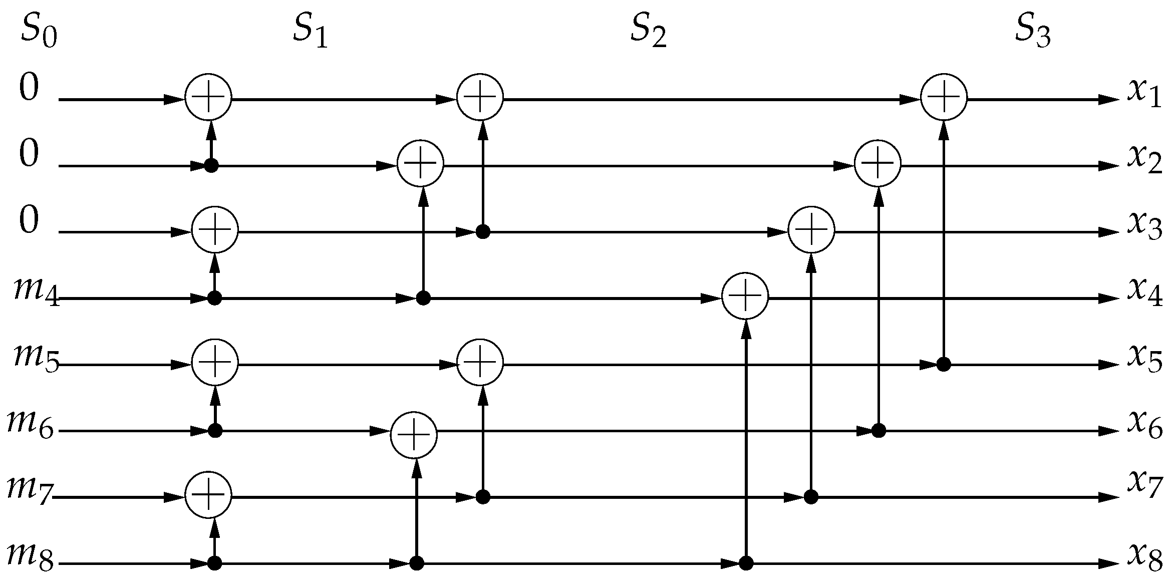
As an example, consider an
polar code with frozen bits set
and information bits set
. The polar encoding for this code is shown in
Figure 2. The encoding process of an
polar code consists of
stages denoted by
. The input to the encoder
is at
. At each subsequent stage, there are
binary additions. For this
polar code,
The nonsystematic generator matrix
selects the rows in
of
, i.e., the last five rows to transmit information bits:
Reed–Muller (RM) codes [
52] are closely related to polar codes. Both codes with codeword length
N use the same matrix
for code construction. While the generator matrix of polar codes selects the most reliable rows with the lowest error probabilities of
based on the specific channel and SNR, the generator matrix of
RM codes with order
r and codeword length
selects the rows of
with Hamming weights
. Equivalently, polar codes freeze the least-reliable channels, while RM codes freeze the channels with the lowest Hamming weights. Consequently, polar codes have a better error performance, since the code design is channel-specific to improve error performance, while RM codes have a higher minimum Hamming distance.
The Log likelihood ratio (LLR) for the
ith bit channel is given by the following:
With SC decoding, each bit is decoded successively from
to
. The decoder employs the following decision rule for the
ith bit:
The calculation of (
25) can be performed recursively in the log domain [
53]:
where
is the subvector of
with odd indices, and
is the subvector of
with even indices. The recursion continues until we reach the calculation of LLR of
. In this case,
is called the channel LLR, which can be calculated from the channel. A more detailed description of SC decoding can be found in [
23].
The SCL algorithm is a modified version of SC decoding and follows a similar serial decoding process from
to
. While SC decoding only considers the best decoding result, SCL decoding forms a list of
best possible decoding results. The decoding result in the SCL algorithm is named as a candidate path having a path metric. In the log domain, the path metric
of the
lth candidate path at the
ith bit is defined as follows [
54]:
A smaller path metric corresponds to a higher
, which indicates a higher likelihood for that candidate path. The updating rule of the path metric at bit index
i is as follows:
Equation (
31) indicates that if the decoding result of list
l for bit
i does not coincide with the corresponding LLR, then a penalty
is added to the path metric.
Before decoding
, the initial path metrics are all set to 0. When decoding a frozen bit, the value 0 is appended to all candidate paths, and the path metrics are updated. When decoding an information bit
, instead of making a hard decision using (
26), the SCL decoder appends both possible decoding results of 0 or 1 to the identical copies of the current decoding candidates, which doubles the number of active candidate paths. When the number of candidate paths exceeds
, only the
candidate paths with the lowest path metrics are kept, and others are pruned. After decoding
, the active candidate path with the lowest path metric is selected to be the final decoding result. By using a lazy-copy technique to duplicate the candidate paths, the decoding complexity of SCL decoding is
[
30].
3.2. Systematic Polar Encoding for the Multi-Way Relaying System
For any non-systematic linear block code with generator matrix
, there exists a systematic equivalent code with systematic generator matrix
[
55], satisfying the following relation:
where
is a
invertible matrix. A code and its systematic equivalent form have the same codewords. Only the mappings of the information vector to codewords are different. These mappings are related through a linear reversible transformation represented by the matrix
of (
32).
We define
as the
submatrix of
of (
20) that consists of elements
with
. The matrix
is lower triangular with diagonal elements
,
. The diagonal elements of
are
with
, which are also diagonal elements of
. Therefore, the diagonal elements of
are also all equal to 1, and
is invertible. The systematic encoder in [
35] chooses
. However, with this selection, the information bits are located at all bit indices in
of the codeword
, which we denote as
. In our system, the bits transmitted by the terminals
are located at the first
K bit indices of
. Therefore, the columns of
are first permuted before the construction of the equivalent systematic generator matrix. We define the resultant matrix from permuting the columns of
as
, which has the following form:
where
is a
submatrix of
that consists of all elements
with
. The systematic generator matrix of the system is formed as follows:
The codeword
can be obtained from either
or
:
Therefore, the information bits transmitted by the terminals,
, and the information bits of the original non-systematic polar code,
, are related by the following:
Encoding at the terminals is performed using
, while polar decoding retrieves
. However, after
is recovered using the SC or SCL algorithm,
can be obtained from (
36). Notice that (
36) can also be viewed as an encoding of
using the generator matrix
, which can be implemented recursively as in polar encoding.
3.3. Polar Decoding of the Multi-Way Relaying System
At each terminal receiver, the received symbols in one time slot are first reversely permuted to make the input order consistent with the non-systematic polar code required by SC or SCL decoders. The input channel LLRs of the decoder are calculated as follows:
where
does not depend on
; thus,
.
The conditional PDF
follows a multivariate complex Gaussian distribution when
is known, and it has the following form [
56]:
In the log domain,
Therefore, the channel LLRs in (
37) can be written as follows:
The LLR becomes
Each terminal
knows its own information bit
; thus, when
,
Similarly when
,
Therefore, the decoder at
sets the channel LLR corresponding to
to the following:
In the simulations, the positive infinity and negative infinity in (
44) are set to
and
, respectively.
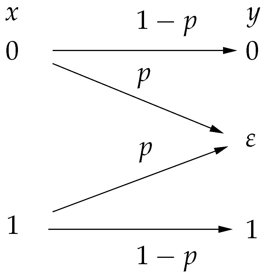
Next, we consider the channel LLRs for the silent relays. In our system, if a relay detects a wrong symbol and does not transmit, the terminals will receive only noise; hence, this sample should not be taken into account in the decoding process. This idea is encapsulated by the notion of the erasure channel. The basic binary erasure channel (BEC) model [
23] is shown in
Figure 3. The transition probabilities of BEC are given by
, where
is the erasure symbol. In general, if the received signal is unreliable and hence cannot be demodulated properly, then the receiver declares an erasure denoted by a specific symbol,
. In our system, an erasure corresponds to the event that a relay remains silent and hence the terminal receives only noise.
Since
, the corresponding channel LLR is set to the following:
Hence, such a sample does not influence the decoding process.
The polar decoding process for the multi-way relaying system is summarized as follows [
57]:
3.4. Complexity Analysis of Polar Codes and Comparison
The encoding process of polar codes in the MWRN considered in this work is identical to the process described in
Section 2; thus, the encoding complexity is the same. For the decoding process, each terminal first performs a reverse permutation of the received signal vector
. The complexity of the reverse permutation is
. Since we use the original SC and SCL decoders, the complexities of SC and SCL decoding in our system are still
[
23] and
[
30]. For the final polar re-encoding process, we use the recursive structure of polar encoding, which has a complexity of
. In summary, the total decoding complexity at each terminal is
for SC decoding and
for SCL decoding. The complexity at each node when employing polar codes is presented in
Table 4.
Next, we analyze the number of required operations at each step for polar codes with SC decoding. The indices used for the reverse permutation are pre-stored in a table; thus, the reverse permutation step only requires
N table look-ups. Calculating one channel LLR using (
40) requires three multiplications and two additions; thus, calculating the total
N channel LLRs requires
multiplications and
additions. According to (
27), each term requires three comparisons and one multiplication, and each term in (
28) requires one comparison and one addition. There are
terms; hence, (
27) requires
multiplications and
additions, and (
28) requires
multiplications and
additions in total. The bit decision step in (
26) requires
N table look-ups to check whether the bit is frozen and
K LLR comparisons for the decision of information bits. The re-encoding process consists of
stages. At each stage, there are
additions. The total number of operations of each step for SC decoding is summarized in
Table 5. For SCL decoding, the number of operations is related to the location of frozen bits and the path metrics, which is about
times of SC decoding.
The total number of required operations for polar codes with ML and SC decoding, as well as LDPC codes with log-BP decoding, is summarized in
Table 6. For example, a
polar code requires 3840 multiplications and 5632 additions to decode a codeword using the SC technique. The
LDPC code in [
12] has
and
. When ignoring the operations in the initializations, the log-BP decoder requires 8740 multiplications and 42,898 additions for one iteration. This indicates that even when
, the total number of operations required by polar codes with SC decoding is much lower than that of LDPC codes with log-BP decoding. The SC decoding complexity behaves as
, which in general, is lower than the complexities of the other two algorithms, log- BP and ML. Therefore, the low decoding complexity of polar codes make them attractive for MWRN applications.
3.5. A Hard Threshold Technique at the Terminals
In practice, it is not possible for a terminal to know whether a relay transmits. In ref. [
12], a hard threshold method at the terminals is proposed to overcome this problem. A terminal will consider a relay as active if the magnitude of the received signal passes the threshold. This can be cast as a binary hypothesis testing problem on the received sample
Y at the terminal:
The corresponding likelihood ratio test is as follows:
The probability of correct detection is denoted by
, and the probability of a false alarm is denoted by
. In [
58], it is shown that the threshold
that maximizes
is
. Ref. [
12] shows that this test becomes the following when simplified:
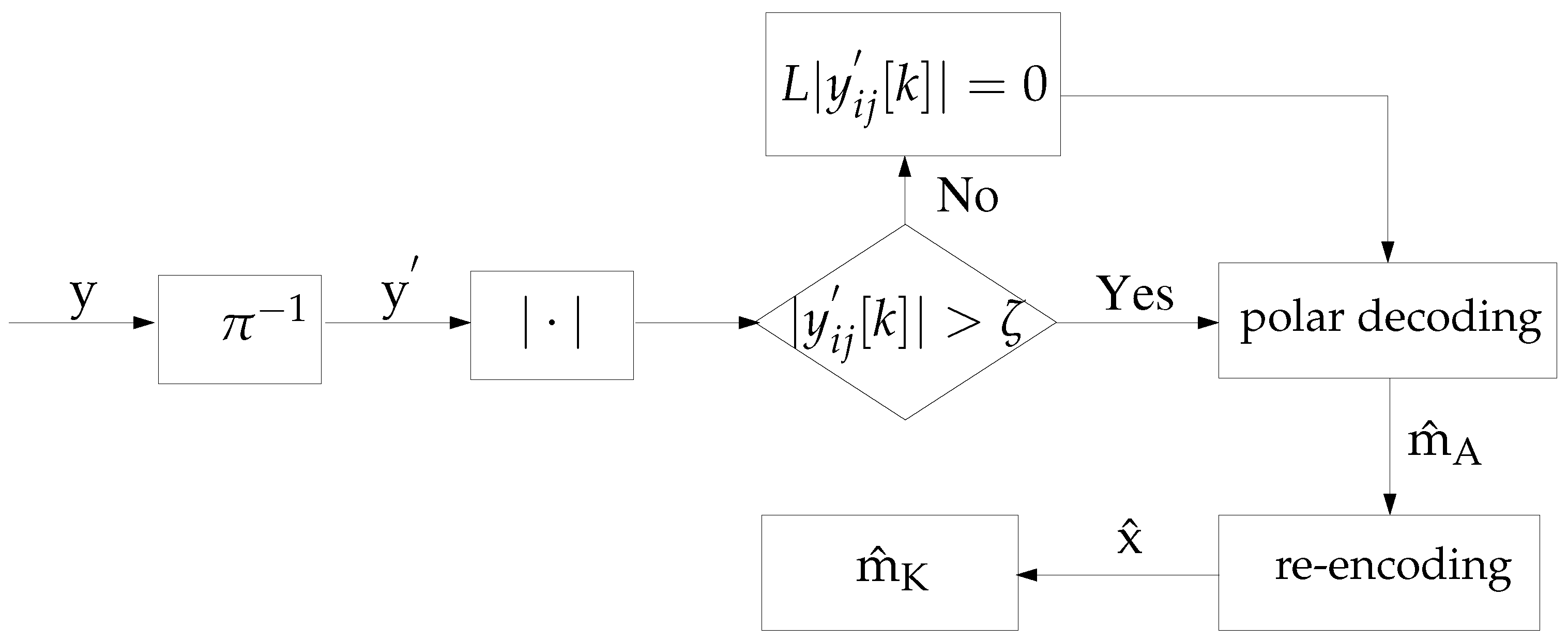
We consider a similar technique adapted for our MWRN with polar codes. In our system, if the received signal from a relay does not pass the threshold
, then the channel output most likely consists only of noise, indicating that the corresponding relay is silent. Hence, in this case, the signal at the terminal is interpreted as an erasure for decoding purposes, and the corresponding LLR
is taken as in (
45). The receiver algorithm with the hard threshold for our system is presented in
Figure 4.
At each terminal, comparing the received signals from all the relays with the hard threshold requires a complexity of . Hence, adding the threshold does not affect the decoding process complexity. Therefore, when employing the threshold method, the complexity is still for SC decoding and for SCL decoding at each terminal.

