Article

Cluster-Based Transmission Diversity Optimization in Ultra Reliable Low Latency Communication

1
Information & Communication Technology, Mawlana Bhashani Science and Technology University, Tangail 1902, Bangladesh
2
Institute of Information & Communication Technology, Bangladesh University of Engineering and Technology, Dhaka 1205, Bangladesh
3
Computer Science and Engineering, Mawlana Bhashani Science and Technology University, Tangail 1902, Bangladesh
*
Author to whom correspondence should be addressed.
Network 2022, 2(1), 168-189; https://doi.org/10.3390/network2010012
Submission received: 5 December 2021 / Revised: 12 February 2022 / Accepted: 2 March 2022 / Published: 17 March 2022

Abstract

:
Intra-vehicular communication is an emerging technology explored spontaneously due to higher wireless sensor-based application demands. To meet the upcoming market demands, the current intra-vehicular communication transmission reliability and latency should be improved significantly to fit with the existing 5G and upcoming 6G communication domains. Ultra-Reliable Low-Latency Communication (URLLC) can be widely used to enhance the quality of communication and services of 5G and beyond. The 5G URLLC service is highly dependable for transmission reliability and minimizing data transmission latency. In this paper, a multiple-access scheme named Cluster-based Orthogonal Frequency Subcarrier-based Multiple Access (C-OFSMA) is proposed with 5G URLLC’s high requirement adaptation for intra-vehicular data transmission. The URLLC demanded high reliability of approximately 99.999% of the data transmission within the extremely short latency of less than 1 ms. C-OFSMA enhanced the transmission diversity, which secured more successful data transmission to fulfill these high requirements and adapt to such a network environment. In C-OFSMA, the available sensors transmit data over specific frequency channels where frequency selection is random and special sensors (audio and video) transmit data over dedicated frequency channels. The minimum number of subcarrier channels was evaluated for different arrival rates and different packet duplication conditions in order to achieve 99.999% reliability within an air-interface latency of 0.2 ms. For the fixed frequency channel condition, C-OFSMA and OFSMA were compared in terms of reliability response and other packet duplication. Moreover, the optimal number of clusters was also evaluated in the aspects of the reliability response for the C-OFSMA system.

1. Introduction

The application of wireless sensor connectivity is utterly transforming the entire industrial landscape. Due to the wireless sensor-based architecture’s flexibility, mobility, cost efficiency, and scalability, it is considered a key enabler for the current Industry 4.0 paradigm [1,2]. The market value of Wireless -Sensor-Network(WSN)-based applications was USD 46.76 billion in 2020 and is anticipated to reach up to USD 123.93 billion by 2025 [3]. Researchers in the field of WSNs are currently working feverishly to develop interruption-free and collision-free transmission techniques because sensor nodes are used in a multitude of applications, including mission-critical environments, industrial automation, real-time operational processes, intelligent transportation for Electric Vehicles (EVs), target-oriented services, next-generation network services, tactile networks, virtual reality, and many others [4]. To support different emerging applications, the 3rd Generation Partnership Project (3GPP) has defined three broad categories of services in the 5G New Radio Standard as: evolved Mobile Broadband (eMBB), Ultra-Reliable and Low-Latency Communication (URLLC), and massive Machine-Type Communication (mMTC) [5]. URLLC strictly maintains higher reliability within a stringent latency for time-critical application such as modern intra-vehicular communication. A modern vehicle has around 60∼100 numerous wireless sensors such as the fuel sensor, ultrasonic sensor, exhaust gas sensor, and video–audio sensor, for real-time safety applications, monitoring traffic conditions, and environmental conditions, etc. [6,7]. A metaphorical wireless sensor-equipped vehicle is presented in Figure 1. Three different types of sensors (general, audio, and video sensors) are placed in different locations of the vehicle, which ensures the expected reliability and latency. Relying on the latency requirement, URLLC comes in two forms: long-term Ultra-Reliable Communication (URC), and short-term URC [8]. The long-term URC applications demand a latency of >10 ms, and short-term URC ensuring demands a latency of ≤10 ms. Long-term URC is appealing for use in cases that require resilient wireless connectivity, such as disasters or emergency scenarios. There are remote interactions with a higher latency budget, such as adjusting the flight route of a drone. Short-term URC maintains a very stringent latency in applications, such as communication among machines and robots [9].
Latency and reliability are completely contradictory concepts. The latency requirement significantly increases to attain a high transmission reliability. In mission-critical environments such as intra-vehicular sensor communication, it is extremely challenging to achieve high reliability within a stringent latency of ≤1 ms. However, in our survey, an intra-vehicular communication environment, a WSN scheme with low latency and high transmission reliability has not been implemented yet. All the previous works were based on more than 5 ms latency. To overcome this constraint, we devised a scheme that effectively addresses short-term URC. The main focus of this article was not only to ensure short-term URC, but also to maintain higher reliability for intra-vehicular communication. URLLC ensures a packet transmission reliability of 99.999% while maintaining a transmission latency of ≤1 ms. In this paper, a Cluster-based Orthogonal Frequency Subcarrier-based Multiple Access (C-OFSMA) communication mechanism is proposed for intra-vehicular sensor-based communication ensuring the standard of URLLC. The total communication area was composed of a finite number of clusters following K-means clustering [10]. A fixed number of orthogonal subcarrier channels were assigned to each cluster to transmit the data packets from the sensor to the receiver end. The different clusters of the network also increased the transmission diversity resulting in the increase in the reliability of the transmission. The proposed C-OFSMA was used to ensure a 99.999% transmission reliability. To achieve this, a short payload was considered with the slotted-Aloha protocol and the packet diversity principle to enhance the transmission reliability [11,12]. Moreover, we also assumed that, in each Transmission Time Interval (TTI), no self-packet collision occurred among the duplicate packets generated from the same sensor.
The rest of the paper is organized as follows: Section 2 briefly discusses the related works. Section 3 presents the system architecture along with the packet transmission and collision scenario and the path loss model of the proposed C-OFSMA system. Section 4 outlines our experiment and discusses the results, and finally, Section 5 concludes the paper with some future directions.

2. Related Work

Current industries emphasize sensor-based wireless application networks to guarantee speedy data transfer in mission-critical applications. Many researchers aim at achieving a very high data transmission reliability in the intra-vehicular network within short latency. Previously, the Controller Area Network (CAN) [13] serves as the foremost way out for intra-vehicular communication which was developed in the 1980s by Robert Bosch GmbH. CAN has always been welcomed due to its low cost and higher reliability. In the last two decades, CAN-C [14] became more reliable for its low latency feature. The network protocol has been widely used for vehicle body electronics, chassis, and power-drain related issues. Without any external interference, the data transfer rate can vary from 125 kb/s to 1 MB/s. However, having low bandwidth and usage of a shared medium in data communication makes the data rate slower [15]. Alongside CAN network, Local Interconnect Network (LIN) [16] was also in the market, but due to the link speed of 20 kb/s [17], it has not stayed in a more extended period. Another x-by-wire application-driven network FlexRay was being developed from 2000 to 2009 [18]. In the task involving safety measurement, FlexRay outperforms the market with a link speed of 10 MB/s [15]. TSN+AVB Ethernet is used in an intra-vehicular environment, and the dashcam unit sends data of 46 Bytes with a uniform distribution of 0.5 ms within to the receiver [19]. However, all of these widely used sensor-based networks have brought a slew of issues: having wired architecture, complex structure, an increase in weight, and a large number of sensor placements. This renders these networks unsuitable for intra-vehicular data transmission scenarios as stringent latency is often required with high reliability.
The wireless network is popular and has replaced the wired architecture. In this consequence, CDMA and OFDM have been taken into consideration in [17], but they did not reveal any experimental procedure. Bluetooth and WiFi have always been acceptable, but there are only some primary tasks to deal with, such as infotainment and multimedia. An IoT enabled Intra-Vehicle Wireless Sensor Networks to increase data communication reliability has been accepted in [20], but they consider a transmission period of 60–120 ms. Another wireless mesh topology named ZigBee has been analyzed the reliability and link speed in [21] for intra-vehicular sensor networks. However, the packet transmission latency for the ZigBee network is 16 ms [22,23] which is still high. The mentioned networks provide high reliability as they can handle high link speeds. However, these schemes caused network instability, interference, momentary failure, and high transmission latency. Table 1 summarizes the comparison of existing protocols. Table 1 summarizes the comparison of existing protocols.
At the end of 2015, researchers predicted that the usages of wireless sensors for intra-vehicular communication would increase significantly in the near future [26,27]. After that, smart vehicles were designed with many sensors, installed in various positions and performing distinct activities, e.g., engine battery, temperature, the battery or fuel level, the pressure of the tire, interior temperature, speed, seat belt, door locks, passengers positions, back-light, or retrofit rain sensor. In the sequence of development, 5G URLLC standards might be ensured collision-free and easy-to-maintenance intra-vehicular communication. The 5G URLLC Quality of Service (QoS) for guided vehicle and automated industries allow packet error rate up to 10 5 and latency 1ms is found in [28]. The 3GPP also sets the same standards (packet error rate and latency) for 32 bytes packet size [29]. The end-to-end latency estimation for spacecraft automation and sensor based communication was found 5 ms in a TDMA protocol [30]. 5G URLLC has been investigated in [31] for real-time application, which is a newer frame structure, well beyond the LTE-advanced frame that can use URLLC latency. This seems to have a reliability requirement for different packet sizes evaluated in a different modulation technique. Using polar OFDM waveform technology, an automated robot has been built [32] ensuring higher reliability. A single OFDM symbol is capable of detecting a packet, minimizing the latency of packet detection to achieve 99.999% reliability [33]. However, in the OFDM system, the packet corresponding bits are divided into subcarriers, and cyclic prefix bits are associated bits to extend the packet length. As a consequence, the OFDM system takes more time. In the intra-vehicular condition, 5G URLLC is extremely challenging due to network system schemes and transmission techniques for wireless sensors as it moves at around 120 Km/h to 250 Km/h. At such speed, a 5.9 GHz band has been used for V2X safety concerning application in the transport industries [34]. 5G URLLC is optimized adequately for mission-critical systems [35,36] where the transmission latency is stringently maintained with fixed reliability. To maintain the 5G URLLC standard, wireless sensor-based Orthogonal Frequency Subcarrier-based Multiple Access (OFSMA) MAC protocol has been accepted in [37]. The OFSMA ensures reliability of 99.999% within 0.1 ms transmission latency for robots internal wired to wireless sensor conversion [11]. A Hybrid Access Scheme (HAS) considers audio, video, and general sensors and utilize OFSMA MAC protocol to ensure transmission reliability of 99.999% having a latency of 0.1 ms [12]. URLLC packet designing is another vital issue. With an accurate packet structure, the packet processing and transmission time latency can be decreased [38]. For this, uplink contention-based access [39] is considered for sporadic arrivals for the URLLC packets. A non-square-shaped packet for the frequency domain is employed in the 5G NR system. The Low-Density Parity-Check (LDPC) helps to reduce transmission latency of the data channel [40]. The packet diversity principle is another influencing concept to increase the transmission reliability of a communication system. A contention-based multi-channel slotted-ALOHA protocol that has been proposed in [39] that used packet diversity principle to improve the transmission reliability. As multiple duplicate packets are sent into different slots, inner packet collisions are reduced. A quick retrial technique to forward a packet into a frequency diversity structure just after collision in a slotted-ALOHA system is proposed in [41] for multi-channel random access in an OFDMA wireless network. A random frequency band is generated in each TTI to improve the throughput, which is analyzed in [42]. The receiver should work more efficiently to receive these data packets to transmit duplicate data packets from different clusters. For multi-connectivity and interface diversity, a Massive Multiple-input Multiple-output (MIMO) is adopted to increase transmission accuracy [9,43] as it utilizes a vast number of antennas. Some of the discussed network schemes are incorporated into MANET and VANET too. However, the proposed work considered only intra-vehicular networks to serve only 1–6 m distance inside a vehicle. Low latency and higher reliability are extremely difficult to achieve for this short-range communication.
The main intention of our proposed C-OFSMA is to increase the transmission diversity that ensures the usages of minimum subcarrier channels to achieve reliability of 99.999% within end-to-end latency of 0.2 ms. The main rationale for choosing 0.2 ms is to use URLLC for intra-vehicular communication. The majority of recent research in this area has focused on 0.2 ms latency in vehicular Communication [44,45]. The C-OFSMA network scheme for intra-vehicular data transmission has not been used yet. As mentioned earlier, a finite number of sensors are placed in different clusters. The cluster-based topology brings more effectivity, and we estimate the optimal clusters are needed to gain a better result. The top contribution of the paper is as follows:
  • We propose the C-OFSMA protocol that ensures higher transmission reliability and minimizes the latency in the intra-vehicular network.
  • We compare C-OFSMA scheme with OFSMA:
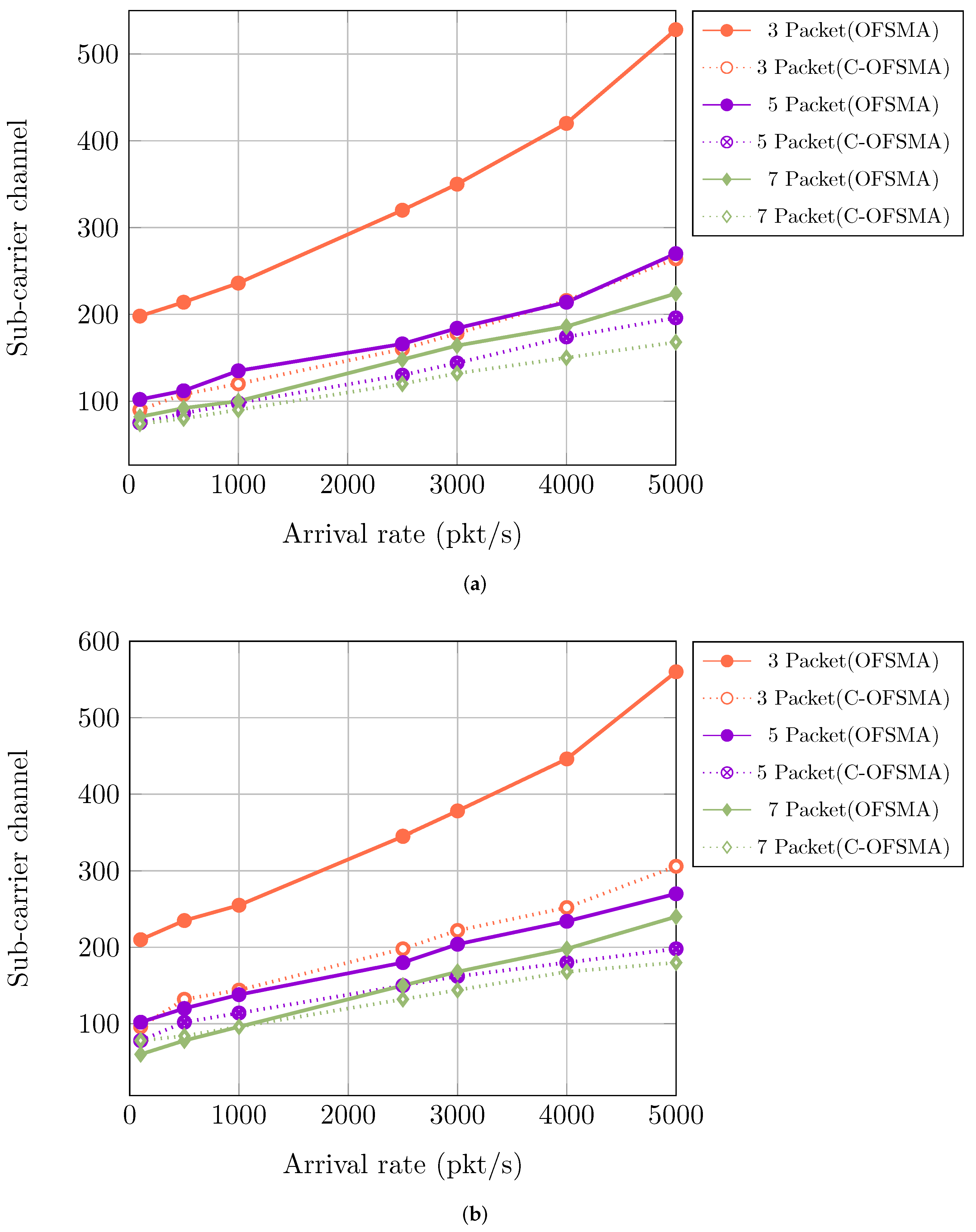
    Evaluating the minimum subcarrier channels to reach the reliability of 99.999% for different packet duplication within stringent latency bound of 0.2 ms.
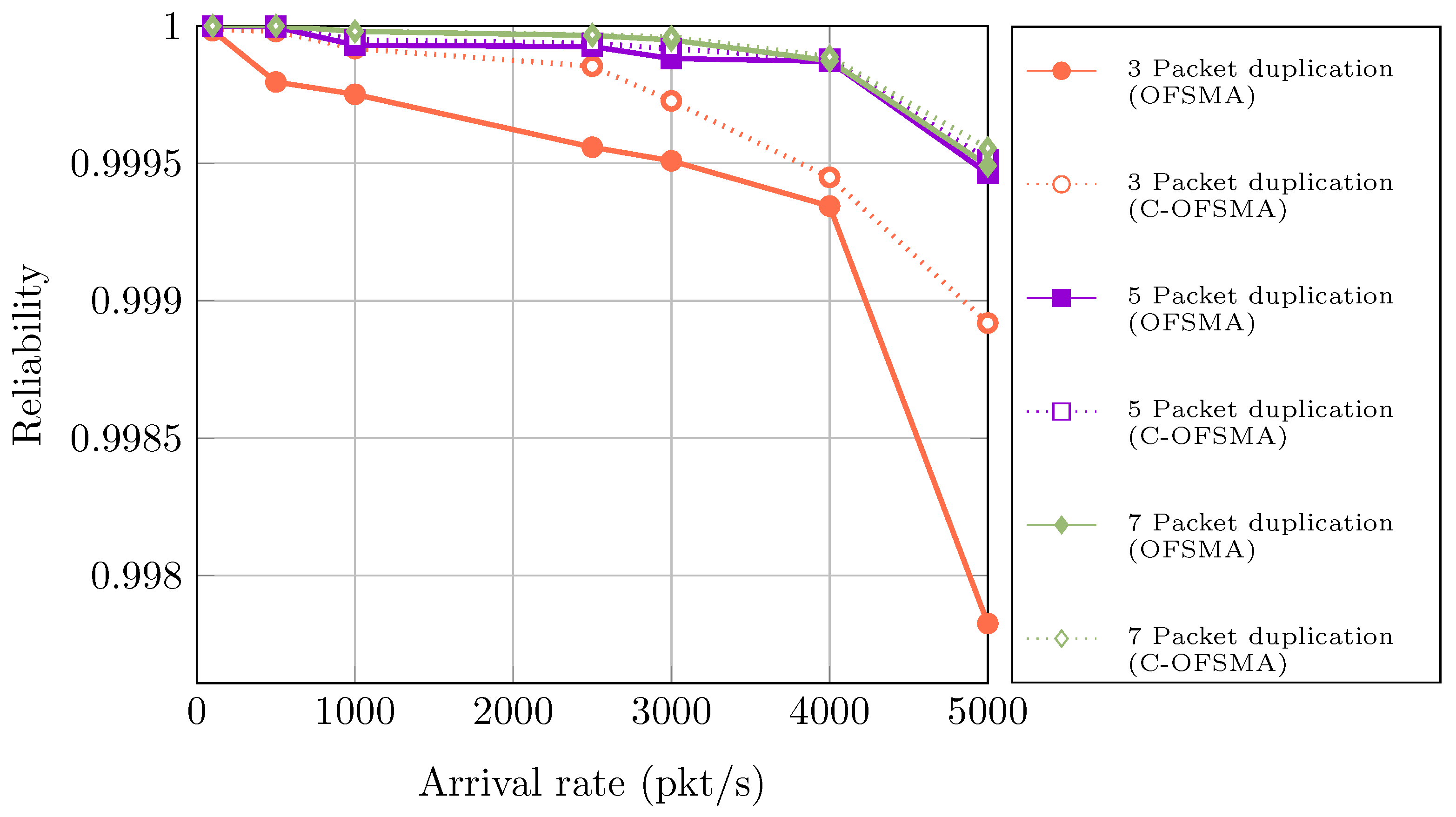
    Evaluating reliability responsiveness, using fixed channels condition.
  • We evaluate the optimal number of clusters for different packet duplication in terms of reliability analysis.
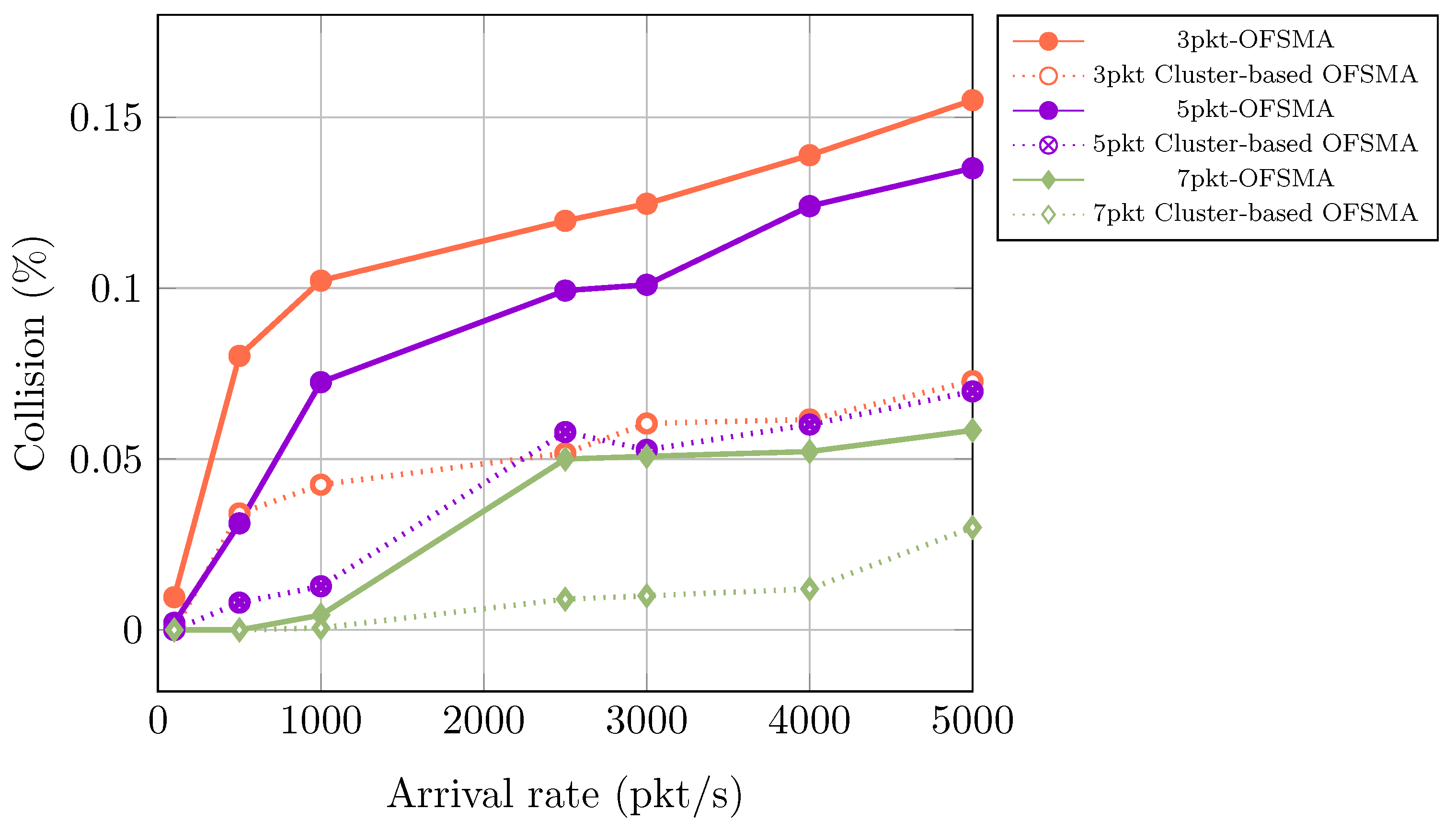
  • We determine the collision probability for different packet duplication at different arrival conditions.

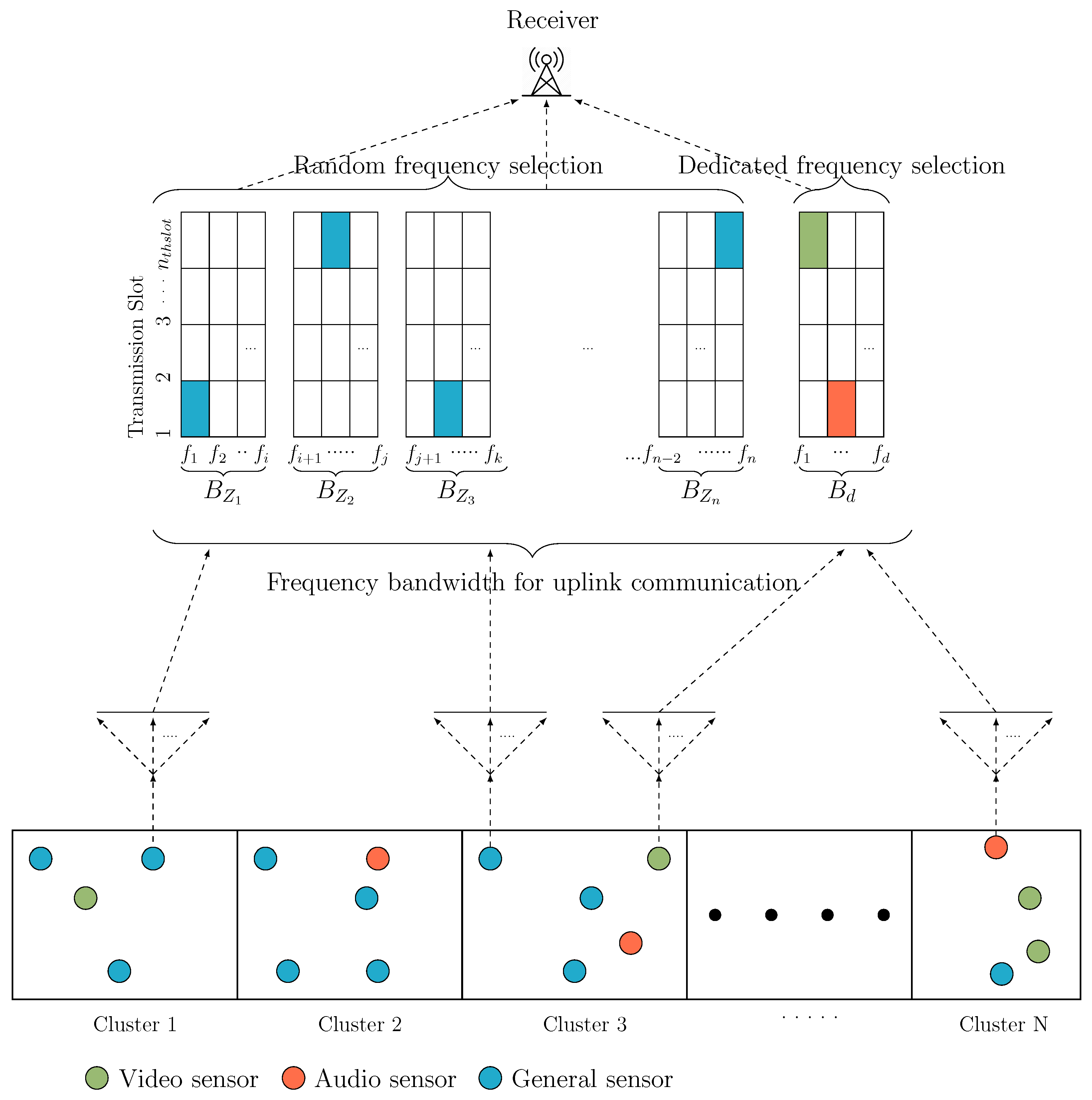
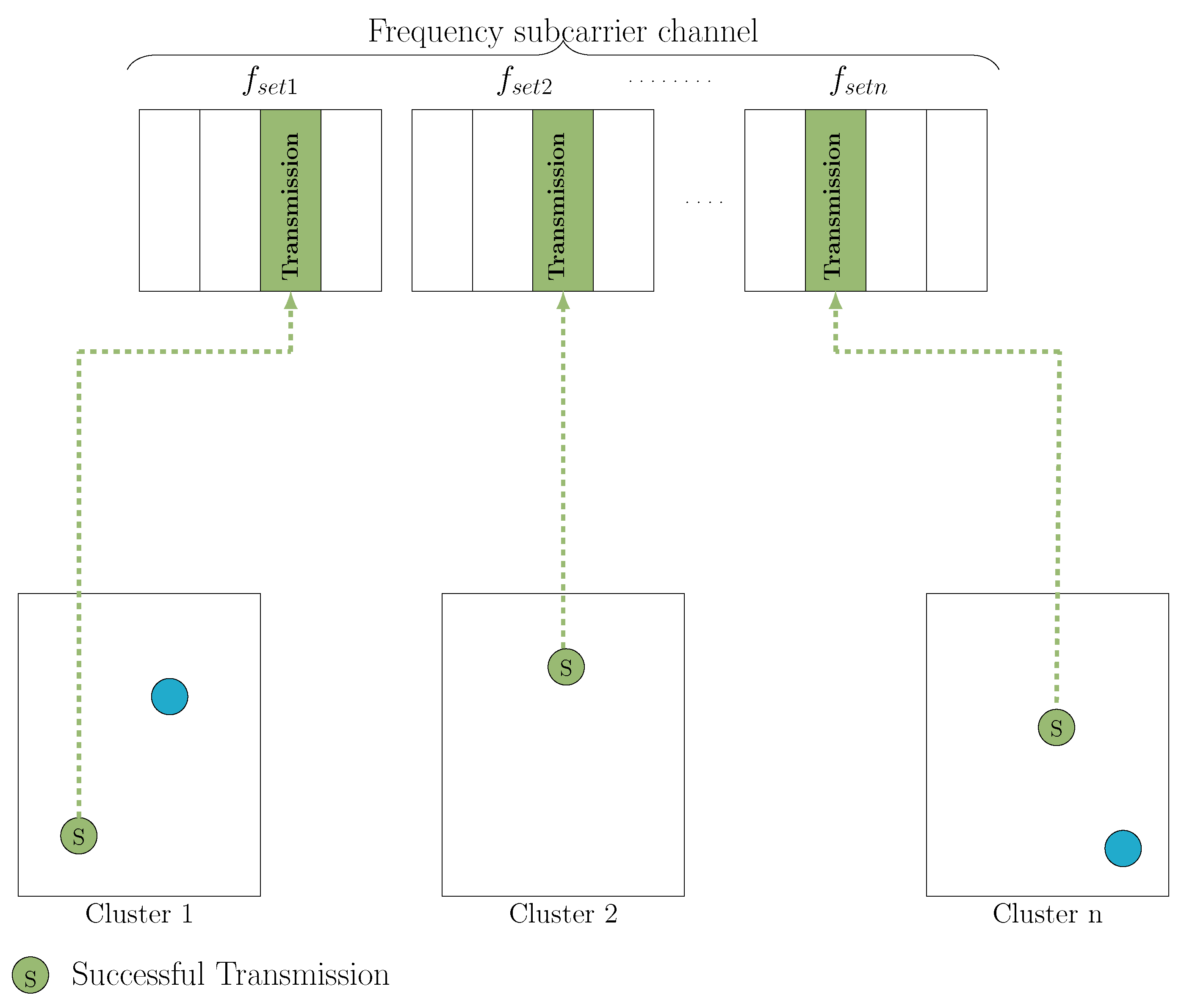
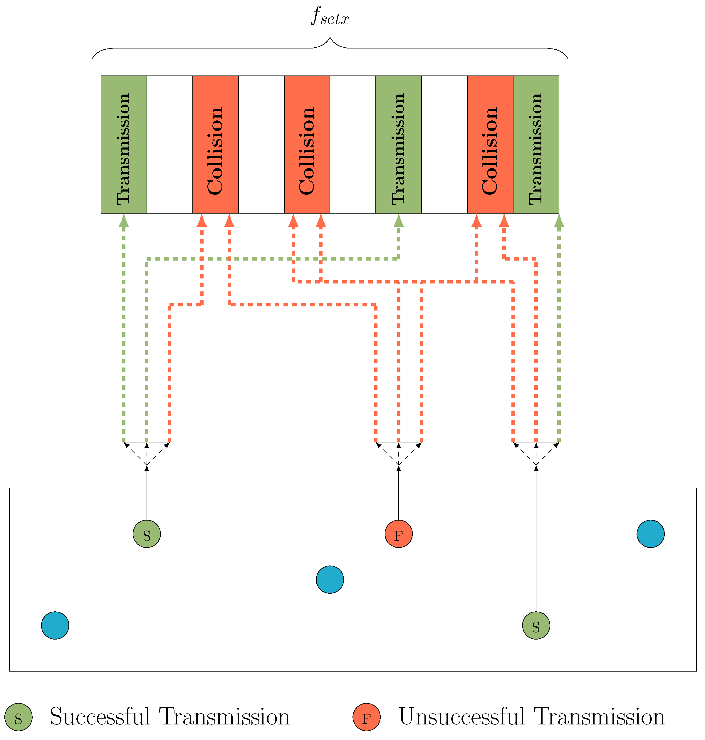
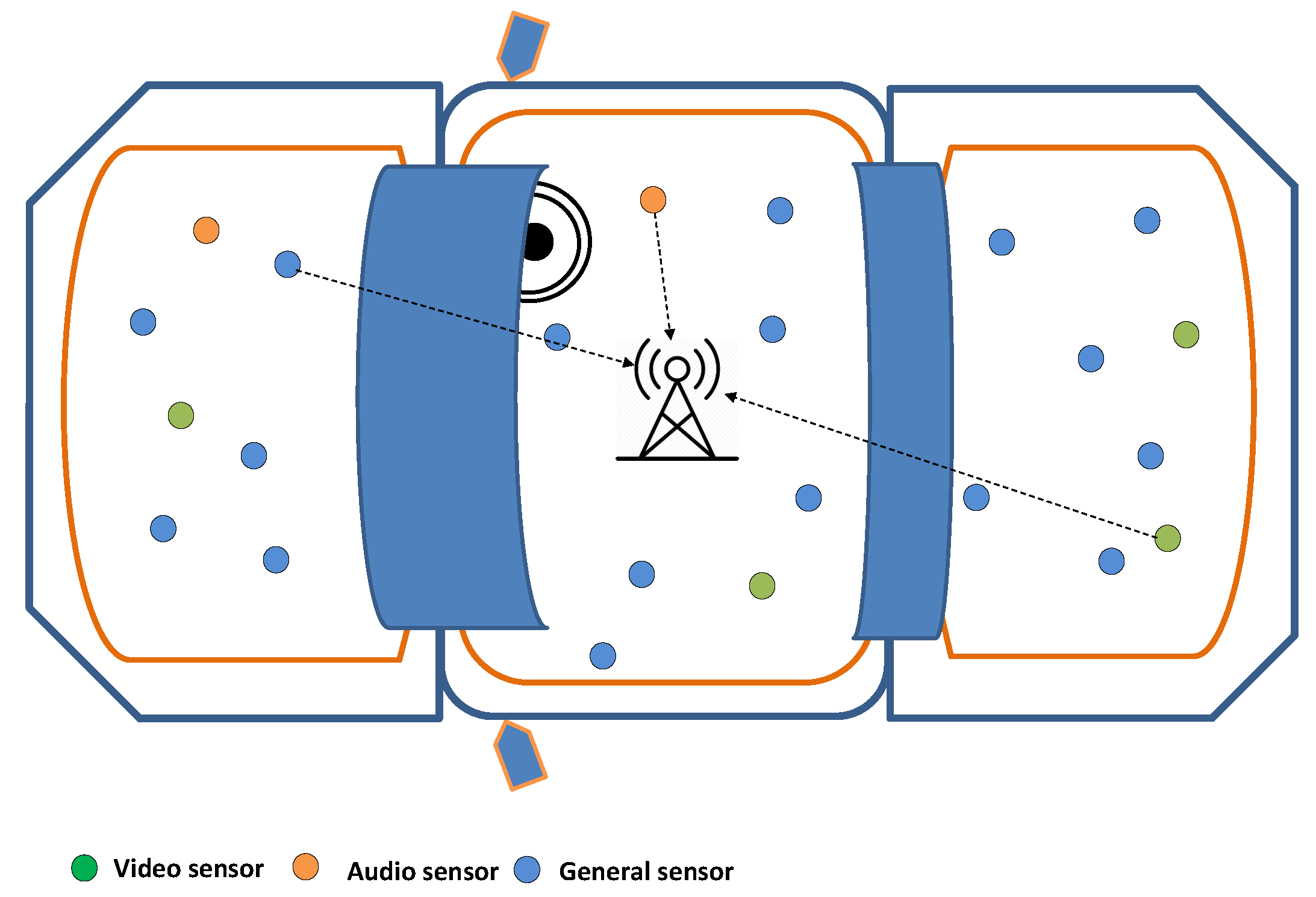
3. System Architecture

In Figure 2, a cluster-based uplink wireless sensor communication architecture has been considered. In this network, three different types of sensors (General, Audio, and Video sensors) were randomly plotted into different clusters. The clusters are represented as Z x = ( Z 1 , Z 2 , Z 3 , …, Z n ). The system bandwidth B is uniformly assigned to the different clusters Z x . Each cluster bandwidth B z x can be calculated as:
B z x = B Z x
The system considered a range of frequency for each cluster B z x = B z 1 , B z 2 , B z 3 , …, B z n and the number of sensor nodes and subcarrier channels are different. There is a dedicated bandwidth assignment for the special sensors (audio and video sensors) as B d . The general sensors transmit their data over randomly selected frequency subcarrier channels from assigned bandwidth B z x . The system considered S x number of general sensors exist per cluster. If bandwidth B z x is assigned in each cluster, then each sensor frequency bandwidth B s x can be evaluated as:
B s x = B z x S x
with every sub-bandwidth B z x having a set of a carrier frequency f s e t x within their selected cluster bandwidth.
f s e t x = ( f a x , f a x + 1 , f a x + 2 , , f b x 2 , f b x 1 , f b x )
In a specific cluster a x and b x defines the starting and ending position of subcarrier frequency set. Here, x = 1, 2, 3, …, n mark cluster number and b 0 = 0. The  a x and b x must be resided between 1 to N no subcarriers. N indicates the number of channels and T g is the total number of general sensors.
b x = b x 1 + N T g × S x a x = b x 1 + 1
Following Figure 1, each general sensor creates d = 1, 2, 3, …, D n duplicate packets for higher data accuracy and S x randomly occupies subcarrier frequency f c from f s e t x
f c R f s e t x
The slotted-ALOHA protocol provides the ability to transfer those duplicated packets into different slots. There are y = 1, 2, 3, …, n × d possible packets that can be sent from each S x using a single slot. For the Z x number of clusters, the signal M S G (t) can be presented as:
M S G ( t ) = y = 1 n × d z = 1 Z x S y z ( t ) e 2 π i f c y t
Here S y z (t) is an in-phase quadrature component as well as a complex baseband signal. In each TTI slot, the specialized audio and video sensor choose subcarrier frequency from the dedicated band B d to have maximum reliability. For a total of AV audio or video frames, the signal M S S (t) can be expressed [30] as:
M S S ( t ) = k = 1 A V S s ( t ) e 2 π i f c k t
Without considering the noise interference, the total signal is:
M t o t a l ( t ) = M S G ( t ) + M S S ( t )
At the receiver end, there’s the employ of massive MIMO, which provides multiple signals from a different cluster and provides multi-connectivity for different packet duplication conditions.

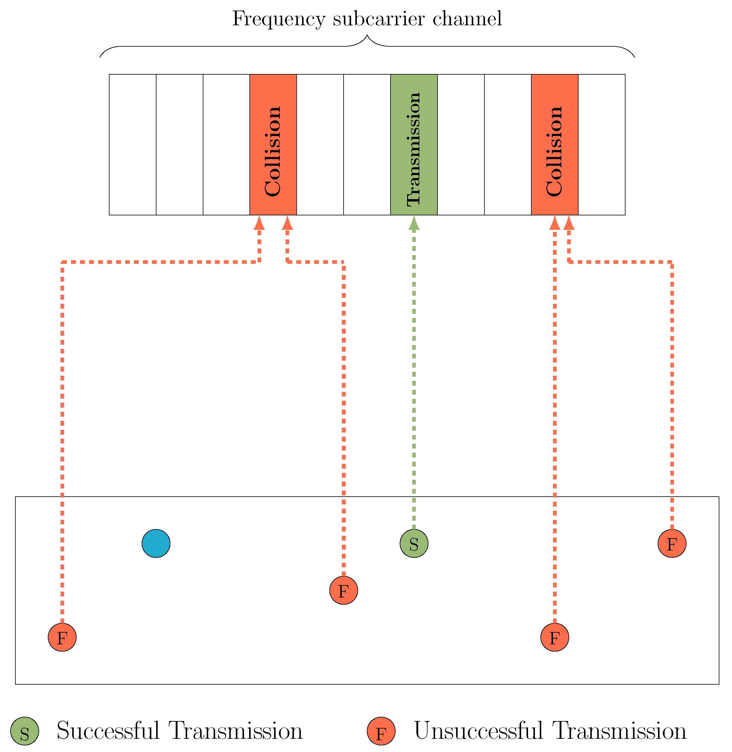
3.1. Packet Transmission Structure

The main priority of C-OFSMA is increasing the rate of successful packet transmission. Multiple sensors can try to transmit duplicate data at a single time slot, and with the packet diversity principle, if at least one packet reaches the receiver end from d n duplicate packet, it will be counted as a successful transmission. In Figure 3, a massive subcarrier channel is assigned to increase successful packet transmission. However, some of the sensors can occupy the same subcarrier channels and create collisions. These collided subcarrier channels cannot afford to transmit data. To achieve 99.999% reliability as in [12], massive subcarrier channels are required.However, our scheme is aimed at minimizing the usage of subcarrier channels which is analyzed in Algorithm 1. Then, the challenge is to achieve 99.999% reliability considering fewer subcarrier channels. In Figure 4, the C-OFSMA provides much better performance in terms of successful transmission. In Figure 5, the packet transmission behavior of a single cluster is shown. Here, packet transmission and collision are both performed. Collision is inevitable, only while multiple sensors from one cluster transmit the duplicate packet, occupying the same subcarrier channels and within a single time slot. Therefore, the probability of a collision is reduced as the system rigidly abides by all of these dependent conditions. For audio and video sensors, dedicated bandwidth B d contains a Dedicated Access Channel (DCA) [12]. DCA provides fixed and unique subcarrier channels to each audio and video sensor to ensure 100% successful transmission.
From Equation (6), the complex baseband signal is considered with 2 quarter cycles (180 degrees or π radians) for general sensors. The equation also shows the number of packet increase considering different cluster. So, Z x clusters for sensors placement with d packet duplication, the total packet in a single slot will be:
P s i n g l e s l o t = d × Z x
However, the higher packet generation increases the chance of collision. Again from Equation (6), the complex baseband signal is considered with 2 quarter cycles ( π radians) and considering the number of pilot subcarriers per symbol ( N r e f = 4) [46] and with T transmission latency and at λ arrival rate with the number of the packet will be 4T λ .
Then to ensure the reliability of 99.999%, the minimum subcarrier channel N can be revealed as:
N = e π + c o l l i s i o n Z x P s i n g l e s l o t + N r e f T λ = e π + c o l l i s i o n d Z x + 4 T λ
Here, T is the latency of 0.2 ms and λ ( p k t / s ) represents different arrival rates.
Algorithm 1 Minimum subcarrier channel detection algorithm for
     Input:
     N ← Number of subcarrier channels
     T g ← Total number of general sensor
     Dup ← Packet duplication
     C n ← Number of cluster                      ▹ Using K-means clustering
     S x ← Number of Sensor in each cluster
     Output:
     M i n c h a n n e l ←Number of minimum channel to Satisfy the reliability 99.999%
1:
Reliability ← 0
2:
Avg_Reliability ← 99.99899%
3:
f c ← Frequency channel
4:
a[] ← starting position of a cluster frequency bandwidth
5:
b[] ← ending position of a cluster frequency bandwidth
6:
T p a c k e t ← Number of total transmitted packet
7:
R p a c k e t ← Number of total received packet
8:
increment ← Increasing the number
9:
while Reliability < Avg_Reliability do
10:
    N ← N+increment
11:
     T p a c k e t ← Dup × T g
12:
    for i ← 1 to C n  do
13:
        b[i] ← b[i-1] + (N/ T g ) × S x
14:
        a[i] ← b[i-1] +1
15:
        for j ← 1 to S x  do
16:
            f c ← random( f a [ i ] , f b [ i ] )    ▹ Randomly select subcarrier within selected cluster frequency bandwidth
17:
        end for
18:
        for k ← f a [ i ] to f b [ i ]  do
19:
            R p a c k e t ← Count number of successful transmitted packet
20:
                       ▹ Using Collision Detection Algorithm from [11]
21:
        end for
22:
    end for
23:
    Reliability ← ( R p a c k e t / T p a c k e t ) × 100
24:
end while
25:
M i n c h a n n e l ← N
The C-OFSMA brings more efficiency than OFSMA. However, there is one caution to mention: as the number of clusters increases, the outcome may differ. Therefore, a precise cluster deployment is calculated in Algorithm 2 to achieve the highest reliability. From BPSK modulation, we know:
T o t a l P a c k e t = s u c c e s s f u l l y t r a n s m i t t e d p a c k e t t o t a l t r a n s m i t t e d p a c k e t + C o l l i d e d p a c k e t
R e l i a b i l i t y = s u c c e s s f u l l y t r a n s m i t t e d p a c k e t t o t a l t r a n s m i t t e d p a c k e t
R e l i a b i l i t y = T o t a l p a c k e t C o l l i d e d p a c k e t
For higher sensors, awake from Z x cluster using different f s e t with the use of different clusters, the transmission is exponentially increased.
T o t a l P a c k e t = T g T g f s e t e ( 2 Z Z 2 )
Here, T g is the total number of general sensors. The overall collision creation scenario is defined in packet transmission structure Section 3.1 based on the Collision Detection Algorithm adopted from [11].
C o l l i d e d p a c k e t = T × l n ( λ P ) f s e t
R e l i a b i l i t y = T g T g f s e t e ( 2 Z Z 2 ) T l n ( λ P ) f s e t
Algorithm 2 Optimal number of Cluster allocation algorithm
     Input:
     N ← Number of subcarrier channels
     T g ← Total number of general sensor
     M ←Maximum Number of clusters
     Output:
     Optimal-Cluster←Number of optimal clusters
1:
reliability-array[] ← 0
2:
for i ← 1 to M do
3:
    reliability-array[] ← Calculate the reliability using Algorithm 1 where C n = i
4:
end for
5:
for j ← 1 to length of reliability-array do
6:
    max-reliability[j] ← find maximum value index[reliability-array]
7:
    Optimal-Cluster ← j(index of max-reliability)
8:
end for

3.2. Path Loss Model

The signal power propagation in an intra-vehicular environment frequently exposes some losses. Establishing an accurate model for path loss precision is challenging. Power in tier architecture, subcarrier bandwidth characteristics, antenna size, and distances from sensors to the receiver are observed. Considering all of these challenges, we choose a simplified path loss model [47] and calculate the received power for the 200 bits data packets. Transmission power P T P has received P R P amount of power in dBm unit by selecting a fixed path loss exponent. The received power equation can be expressed as:
P R P = P T P × C × d d 0 γ
Here, d 0 is the antenna far-field reference distance and d is the transmission distance. Due to scattering occurrences in the antenna near-field, the model is only valid at transmission distance, d r e f e r r e d d i s t a n c e , d 0 , where d 0 is generally implied to be 1–3 m for an environment such as ours. Furthermore, γ is the path loss exponent, and it can vary from 1.6∼3.3. Considering free-space medium and intra-vehicular environments in [48], they take γ = 2 and d 0 = 1 m as referred distance. Here, C is the average channel attenuation, having a constant value for a particular bandwidth. The channel characteristic has an impact on the average channel attenuation. For inexact empirical measurement techniques, set C= 1 to the free space path gain at a distance d 0 , to assume omnidirectional antennas:
C = 20 l o g 10 λ 4 π d 0
Here, λ is the wavelength. The average channel attenuation is −47.87 dB for the 5.9 GHz band. As there is always some noise u in analog signal transmission, we consider a u of 0.1∼1 dB range. So the dBm attenuation can be expressed for received power as:
P R P = P T P + C 10 × γ × l o g 10 d d 0 u
For a vehicle length of 3 m, the transmit power can be varied from − 5 dBm∼−20 dBm. We evaluate a cutoff value of −84 dBm received power at the highest 3 m distance, considering the path loss exponent γ = 2. If the packet has less power than the cutoff value, the receiver will discard the packet immediately.

4. Simulation Results

The performance of the OFSMA scheme and the proposed C-OFSMA are evaluated for intra-vehicular communication. To achieve the standard of the 5G URLLC network, we calculate the minimum subcarrier channels. The simulation result is generated in the MATLAB simulator. Table 2 shows the parameter used in the simulation. The used vehicular network considers the 90 general sensors, specialized 4-audio, and 6-video sensors. These general sensors can transmit 3-, 5-, and 7-packet duplication at different arrival rates using a different number of subcarrier channels. The selection of random subcarrier channels helps to maintain the latency limit. The packet generation and transmission follow the slotted-Aloha system using the poison arrival process. The slotted-Aloha provides 0.2 ms for each slot. For general assessment, different clusters are considered for C-OFSMA in Section 4.1, Section 4.2 and Section 4.4. Section 4.3 calculates the optimum number of clusters for sensors deployment to achieve the best transmission reliability.

4.1. Subcarrier Channel Analysis

Using 5.9 GHz frequency band, the general sensors transmit 3-, 5-, and 7-packet duplication. In Figure 6, to satisfy 99.999% reliability, we determine the minimum number of subcarrier channels for both mathematical and experimental perspectives. We consider 6-clusters for the proposed C-OFSMA scheme and compared it with the OFSMA scheme. Here, Figure 6b indicates the experimental result from Algorithm 1 and Figure 6a represent Equation (10). For 3-packet duplication and at 5000 pkt/s arrival rate, the OFSMA scheme occupies 560 subcarrier channels to achieve 99.999% reliability, whereas the used C-OFSMA scheme occupies 306 channels. The 5- and 7-packet duplication demands lower subcarrier channels than 3-packet duplication. At the same arrival rate, OFSMA scheme requires 270 subcarriers channels, but the used C-OFSMA scheme can perform with only 198 channels. The 7-packet duplication demands 240 subcarriers and 180 subcarrier channels for OFSMA and C-OFSMA schemes, respectively. All the higher arrival conditions starting from 2500 pkt/s in any packet duplication show much better results for C-OFSMA. With the increment of arrival rate, the requirement of subcarrier channels increases. The 7-packet duplication provides a much better result than 3- and 5-packet duplication. However, our proposed C-OFSMA 5-packet duplication needs less number of subcarrier channels than the OFSMA scheme having 7-packet duplication. Unlike 3-packet duplication, the line generated from the mathematical analysis, most of the time for 5-and 7-packet duplication, represent nearly identical lines like the experimental analysis.

4.2. Reliability Analysis

A total of 90 subcarrier channels are used to analyze reliability, and 6-clusters are considered to configure C-OFSMA. In Figure 7, for 7-packet duplication with 5000 pkt/s arrival rate, the proposed C-OFSMA scheme earns the reliability of 99.95555% where the OFSMA scheme earns 99.949165%. At higher arrival conditions, for 5-packet duplication, the C-OFSMA scheme is showing better performance than the OFSMA scheme with 7-packet duplication. At 5000 pkt/s arrival rate, the used C-OFSMA scheme has the reliability of 99.9513% for 5-packet duplication and the OFSMA system has 99.9463%. As usual, 3-packet duplication showed poor results. The advantage of the C-OFSMA scheme is also true for 3-packet duplication by comparing the OFSMA scheme.

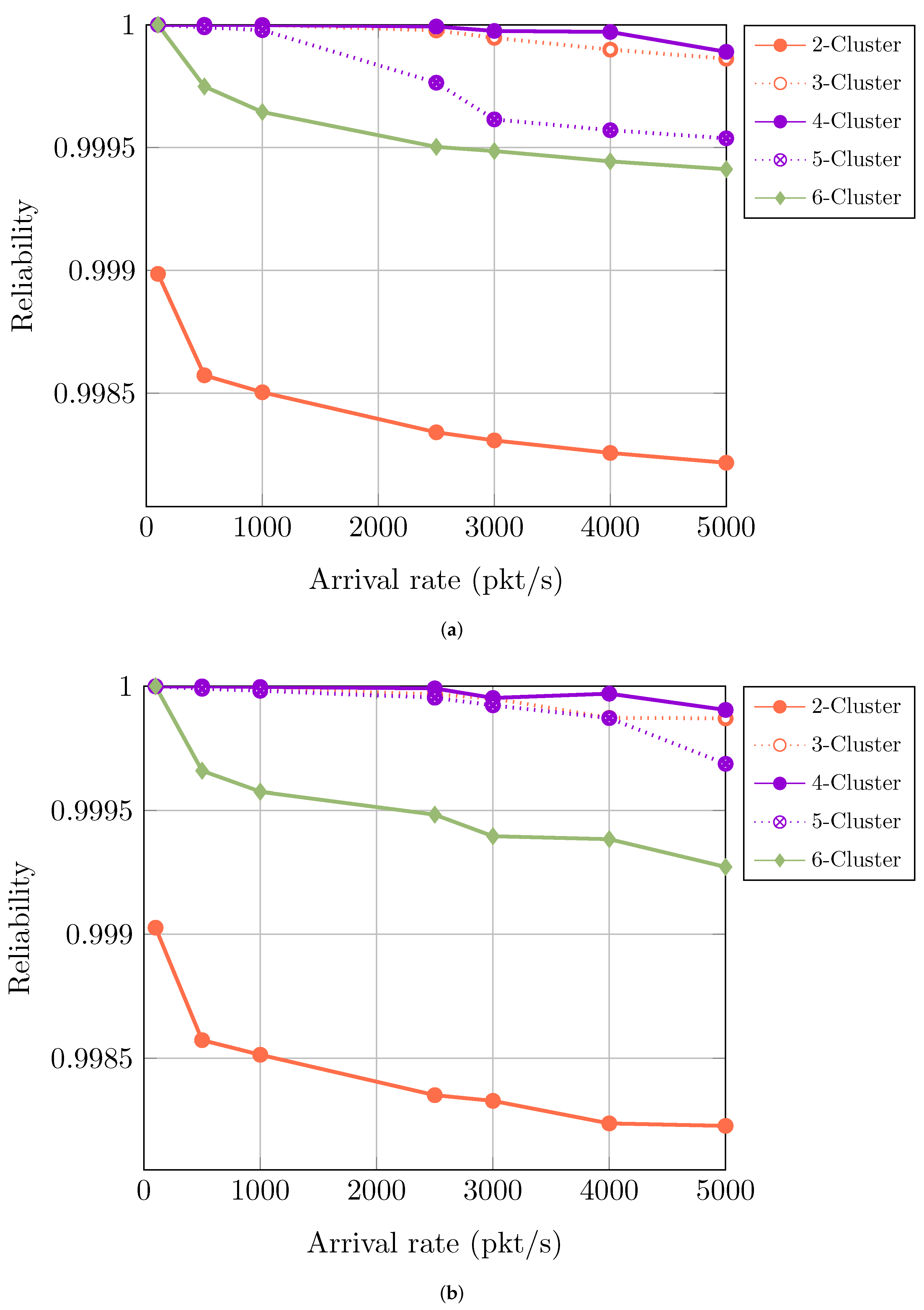
4.3. Optimum Number of Cluster Evaluation

The C-OFSMA performs better than the OFSMA in the previous sub-section. Now, there is a query about how many clusters need to be allocated. It is not quite as though assigning more clusters improves throughput, because using more clusters demands a large antenna at the receiver end, which is prohibitively expensive. Therefore, the sensor placement for cluster optimization is evaluated in Algorithm 2. Finally, the appropriate number of clusters to provide the best reliability is evaluated in Equation (16). Using 90 subcarrier channels, with lower arrival rates, nearly 100% reliability can be achieved for 3-, 5-, and 7-packet duplication. However, this type of intra-vehicular environment performs with high data traffic; fewer data packets transmission is not our prime objective. Therefore, the reliability responsiveness scenario can only be visualized using different clusters at higher arrival conditions for different packet duplication.

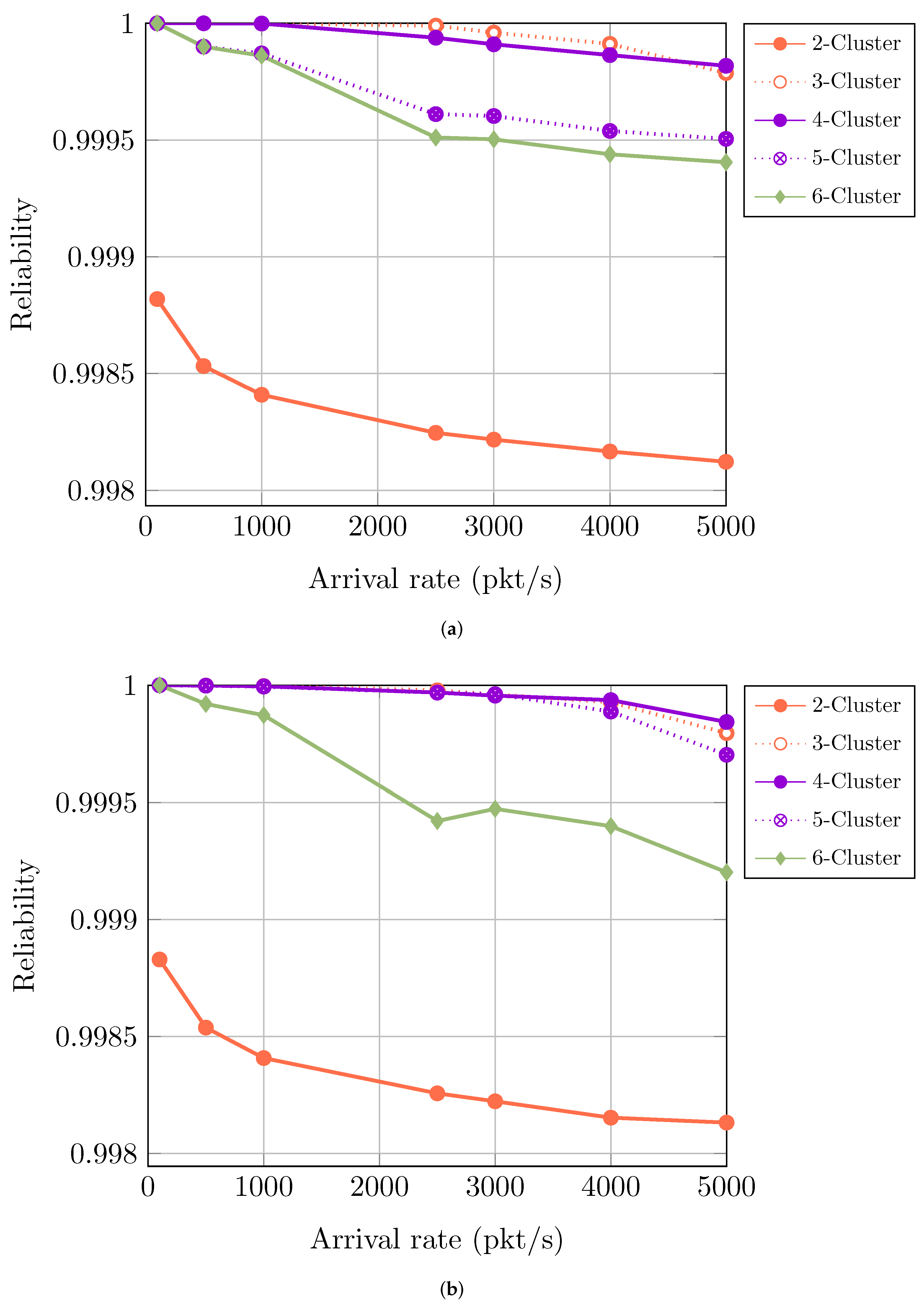
4.3.1. Reliability for Three Packet Duplication

In Figure 8, 3-packet duplication has more reliability when sensors are plotted in 4-clusters. At 5000 pkt/s, 4-clusters achieve reliability of 99.99045%. On the contrary, 2-, 3-, 5-, and 6-clusters at the same arrival conditions achieve the reliability of 99.9272%, 99.98703%, 99.96871%, and 99.8227% respectively.

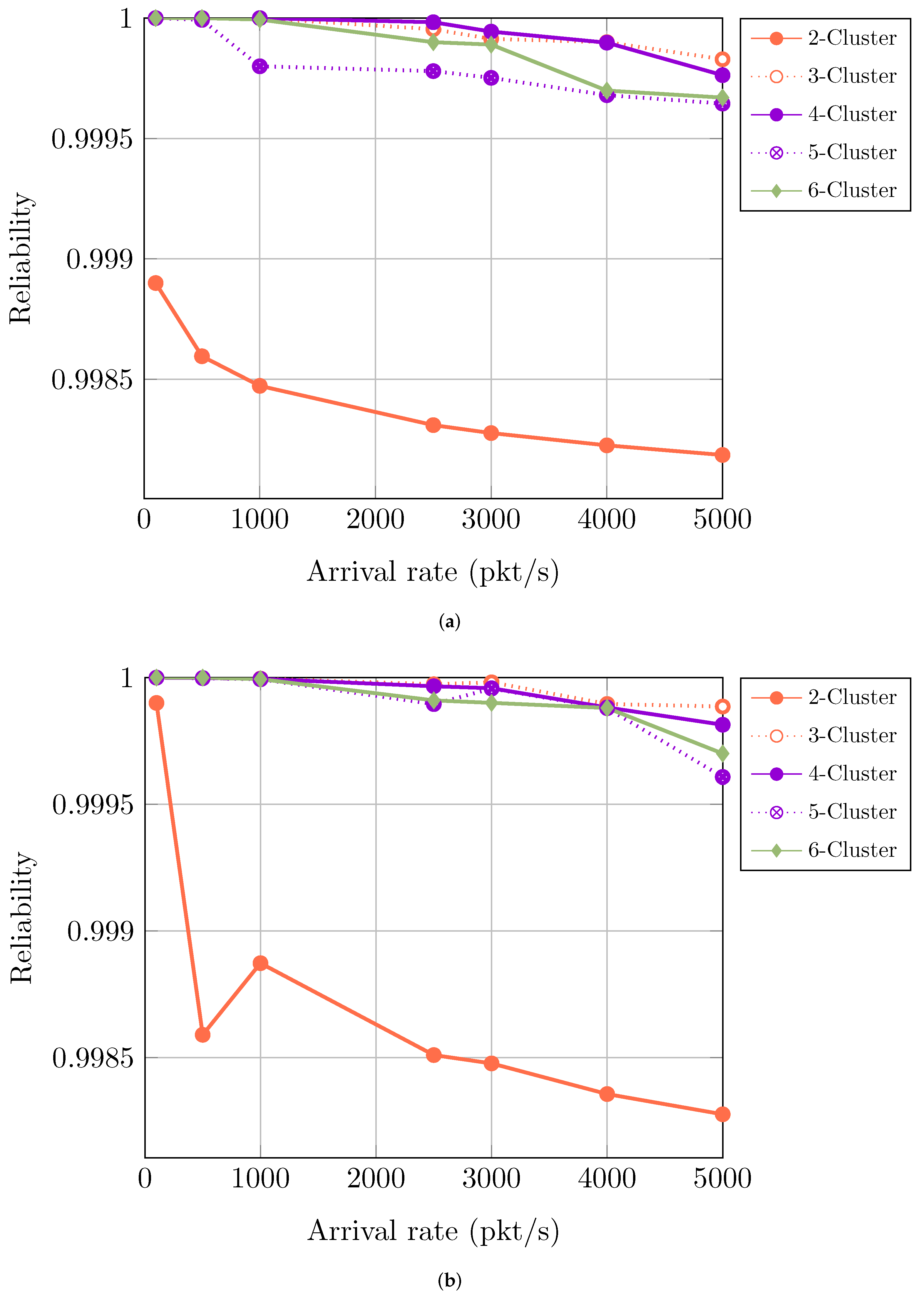
4.3.2. Reliability for Five Packet Duplication

In Figure 9, just like 3-, 5-packet duplication achieves the best reliability of 99.9843% when 4-clusters are used at an arrival rate of 5000 pkt/s. Moreover, 3- and 5-clusters showed nearly identical results, with the reliability of 99.9795% and 99.97027%, respectively. However, the reliability is significantly decreased when sensors are plotted with 2- and 6-clusters, as they achieve reliability of 99.8232% and 99.9202%, respectively.

4.3.3. Reliability for Seven Packet Duplication

In Figure 10, 7-packet duplication achieves the best reliability of 99.9886% when 3-clusters are used at an arrival rate of 5000 pkt/s. Having more duplication, there is a need for fewer subcarrier channels, which eventually reduces the number of clusters—using 120 subcarrier channels with 3-clusters and arrival conditions starting from 100 pkt/s to 2500 pkt/s the 7-packet duplication providing almost 100% reliability. At 5000 pkt/s, the reliability percentage is 99.9886%. If we take 4-clusters, at 5000 pkt/s, the reliability is 99.9814%. A 6-cluster placement offers a better reliability percentage than 5-clusters placement. The 5-clusters provide the reliability of 99.9608%. For 6-clusters, the percentage is 99.9700%. However, 2-clusters have only 99.8276% reliability. So for 3- and 5-packet duplication, we receive the best outcomes from 4-clusters. For 7-packet duplication, 3-clusters is the most suitable.

4.4. Collision Ratio
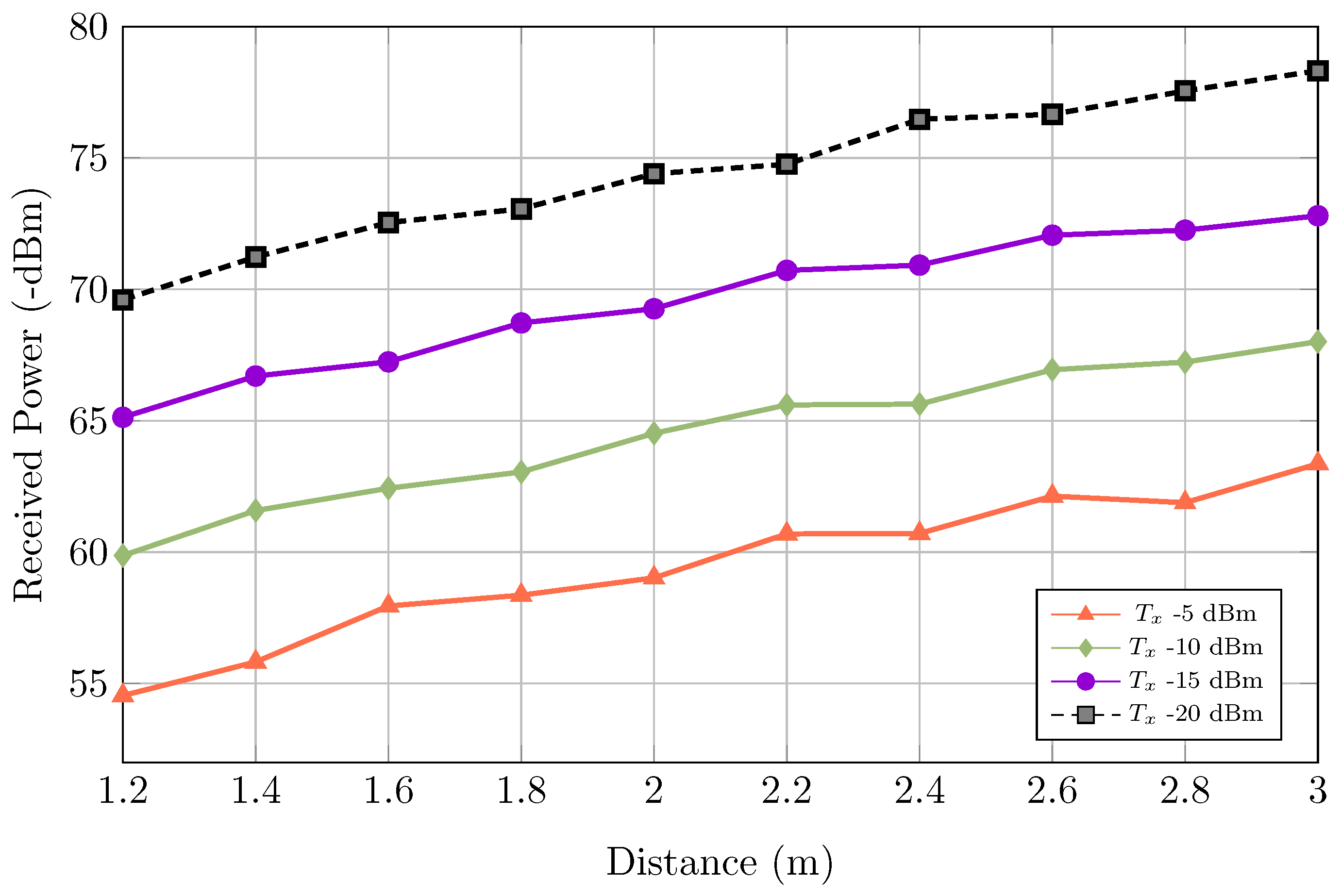
In OFSMA, collision happens when multiple sensors select the same subcarrier frequency channel. On the other hand, in our C-OFSMA, a collision occurs only when numerous sensors from one cluster try to transmit duplicate data and select the same subcarrier. Applying the C-OFSMA model, the overall collision of OFSMA is divided into two categories: inter-cluster collision and inner-cluster collision.
OFSMA   collision = Inter-cluster   collision + Inner-cluster   collision
C-OFSMA   collision = Inner-cluster   collision
Previously in the System Architecture section, we described our system fully minimizes the inter-cluster collision. The overall C-OFSMA collision compared with OFSMA was represented in Figure 11. A fixed 90 subcarrier channels and 6-clusters condition are considered for the proposed C-OFSMA system. In almost all cases of 3-, 5-, and 7-packet conditions, the collision of C-OFSMA is significantly lower than the OFSMA. For example, for 3-packet duplication and at an arrival rate of 5000 pkt/s C-OFSMA collision is 0.0728%, where OFSMA is 0.155%. For 5-packet duplication and at an arrival rate of 5000 pkt/s C-OFSMA collision is 0.0698% for the 6-cluster where OFSMA is 0.1351%. For 7-packet duplication and at an arrival rate of 5000 pkt/s C-OFSMA collision is 0.03%, OFSMA is 0.0584%.
In all higher arrival conditions, without inter-cluster collision, the C-OFSMA shows better reliability than the OFSMA. On the other hand, in almost all lower arrival conditions, the C-OFSMA achieves lower collision than OFSMA except 7-packet in 100 kt/s to 500 pkt/s lower arrival rate condition. For 7-packet 100 pkt/s arrival condition C-OFSMA collision 0.000001% and OFSMA collision 0.000005% and for 7-packet 500 pkt/s arrival condition C-OFSMA collision 0.000001% and OFSMA collision 0.000009%. These indicate the difference between C-OFSMA collision and OFSMA is almost the same. Thw 7-packet duplication creates more duplicated data. When we apply C-OFSMA in 7-packet lower arrival conditions, the inner-cluster collision is increased massively, as the duplicated data are increased along with the lowest arrival condition. This happens because sensors can only select their subcarrier from their f s e t . Consequently, the same subcarrier selection happens frequently. On the other hand, OFSMA conditions have no cluster, so they have no inner-cluster collision as well as the sensors can choose any subcarrier channel within the whole frequency band. The 7-packet 1000 pkt/s arrival condition C-OFSMA scheme collision 0.0006% and OFSMA scheme collision 0.00436%. That means from 1000 pkt/s to the above arrival condition, the C-OFSMA system can minimize the collision and show better performance.

4.5. Path Loss

We estimate the received power for different positions inside the vehicle. As all the general sensors and specialized audio and video sensors are placed randomly, we consider a transmit power range. To calculate received power in different distances, we consider −5 dBm, −10 dBm, −15 dBm, and −20 dBm transmit power, respectively. A fixed path loss exponent is used for the free-space medium, and the referred distance is the distance between the receiver antenna and the closest cluster. From Figure 12, it can be said that as the distance between sensors and receiver antenna increases, the received power decreases. With the increase in transmit power, received power is also increasing. For example, with −5 dBm transmit power, the received power is about −54.54 dBm, having a distance of 1.2 m. At the highest level of 3 m distance, received power decreases to −63.36 dBm. For −10 dBm and −15 dBm received power at 3 m distance, and we have received −68 dBm and −72.8 dBm, respectively.

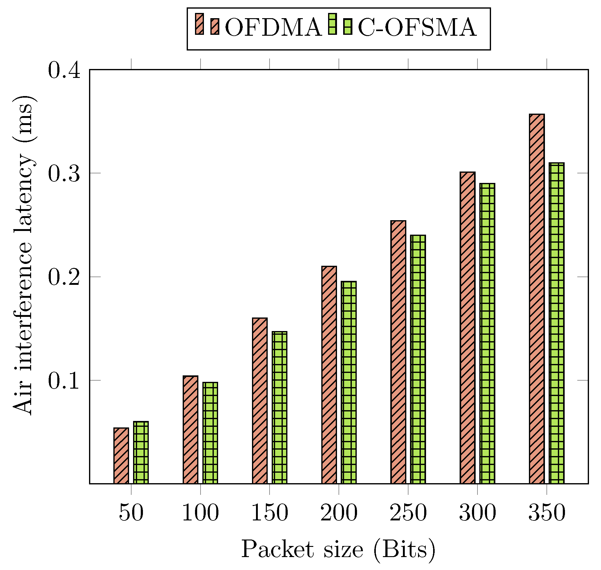
4.6. Latency Calculation for Different Packet Sizes

The OFSMA and C-OFSMA systems packet processing technique is similar, except for the subcarrier bandwidth requirement to achieve high transmission reliability within 0.2 ms air interface latency. Therefore, we chose to compare our proposed scheme with OFDMA for air interface latency calculation. In the OFDMA system, a data packet is divided into several subcarriers with the cyclic prefix appended to each data block. As the OFDMA system’s packet splitting mechanism consumes more time during transmission, the average packet size is growing. However, in the C-OFSMA system, the existing data packet is directly sent to a single subcarrier, and the subcarrier selection is random and unbiased. For simulation, 200 bits packet size is considered. With the increase in packet size, the transmission delay is also increased. Transmission latency depends on the scheme’s propagation delay and the system delay for a single packet. If the system delay of the C-OFSMA scheme is δ , and propagation delay is β , then the transmission latency α can be expressed as
α = δ + β
The system delay, δ is estimated from the simulation platform and is equivalent to the time consumed to transmit the bits from the sensor’s end to the receiver via Gaussian noisy channels. The propagation delay is calculated by the ratio of the packet size ρ and link rate R of the system. So the α can be represented as
α = ρ R + β
For different packet sizes (50–350 bits), we calculate the transmission latency in Figure 13. When considering the 200 bits packet size, the transmission latency is 0.1953 ms. With the expansion of packet size, the transmission latency is significantly increased. So the consideration of taking 0.2 ms latency as transmission delay for 200 bits packet size is justified.

4.7. Discussion

With the emerging applications of URLLC and the fast development of the sensor-based application, a Cluster-based multiple-access scheme named Cluster-based Orthogonal Frequency Subcarrier based Multiple Access (C-OFSMA) is proposed with 5G URLLC’s high requirement adaptation for intra-vehicular data transmission. The URLLC demanded high reliability, approximately 99.999% of data transmission within extreme short latency of less than 1 ms. We consider a short-range uplink communication system where the non-periodic sensors are ubiquitously distributed around the receiver. The Cluster divide, Bandwidth allocation strategy, random channel, and frequency selection are mentioned in the system model in Section 3. When transmitting a single packet from the duplications, a frequency band is first selected. Afterwards, a subcarrier channel f s e t x is also picked randomly. In our proposed system, a diverse number of clusters, frequency band, and subcarrier channels are included to ensure higher reliability of the packet transmission. The C-OFSMA implies that increasing the diversity causes decreasing the minimum subcarrier demands in each frequency band. Furthermore, analyzing the impacts of diverse packet duplication in minimum subcarrier detection and reliability response. Therefore, the C-OFSMA access scheme incorporated the packet diversity principle to ensure the URLLC’s expected 99.999% reliability and random operation allows short-latency within 1 ms packet transmission.

5. Conclusions

This paper proposes a Cluster-based Orthogonal Frequency Subcarrier Multiple Access (C-OFSMA) mechanism for future 5G automated intra-vehicular communication through multiple clusters. This C-OFSMA divides the region into numerous clusters according to the sensor’s location. Moreover, the system also classified the whole subcarrier frequency channel set into recurring frequency subcarrier channel subsets based on the cluster division. The clusters and their subcarrier restrict the sensors to select subcarrier channels from others. The goal behind this is to reduce the collision probability among clusters. The minimum subcarrier channels are evaluated that satisfy the URLLC recommended reliability of 99.999% and latency of 0.2 ms considering the 3-, 5-, and 7-packet duplication conditions.
Simulation results prove that the 3-packet duplication required 306 subcarrier channels, 5-packet duplication required 198 channels, and the 7-packet duplication required 180 channels to satisfy the 99.999% reliability at 5000 pkt/s arrival conditions. In addition, the total number of clusters is also calculated, which are appropriate for gaining higher reliability under minimum subcarrier channels conditions. The system offered significantly greater reliability in fixed 90 channels condition, having 3- and 4-clusters. Additionally, the system reliability under the fixed channel and fixed cluster conditions are also demonstrated through simulation analysis. The proposed mechanism outperforms the URLLC standard for intra-vehicular communication by considering critical aspects.
In a wireless sensor-based MAC protocol, energy consumption is a significant factor. Moreover, with the rapid growth of Electric Vehicles (EV), energy efficiency will draw more attention. Therefore, as possible future work, the proposed system will evaluate the energy performance transmitting, receiving, and regarding CPU for the sensor nodes, and might be applied for EV application. Finally, the proposed mechanism can be verified in other time-critical applications other than advanced vehicular communication.

Author Contributions

Conceptualization, M.A.H. and M.A.H.S.; methodology, M.A.H.S. and B.; software, M.A.H.S. and B.; validation, M.A.H., B. and M.A.H.S.; formal analysis, B. and M.A.H.S.; investigation, M.A.H. and A.K.; resources, M.A.H., M.M.R. and A.K.; data curation, M.A.H.S. and B.; writing—original draft preparation, M.A.H.S., A.K. and B.; writing—review and editing, M.A.H.S., M.A.H., A.K. and B.; visualization, M.A.H.S. and B.; supervision, M.A.H.; project administration, M.A.H. and M.M.R. All authors have read and agreed to the published version of the manuscript.

Funding

This research received no external funding.

Conflicts of Interest

The authors declare no conflict of interest.

Abbreviations

The following abbreviations are used in this manuscript:
C-OFSMACluster-based Orthogonal Frequency Subcarrier-based Multiple Access
OFSMAOrthogonal Frequency Subcarrier-based Multiple Access
URLLCUltra-Reliable Low-Latency Communication
WSNWireless Sensor Network
3GPP3rd Generation Partnership Project
eMBBevolved Mobile Broadband
mMTCmassive Machine Type Communication
URCUltra-Reliable Communication
TTITransmission Time Interval
CANController Area Network
LINLocal Interconnect Network
CDMACode-Division Multiple Access
OFDMOrthogonal Frequency-Division Multiplexing
QoSQuality of Service
HASHybrid Access Scheme
LDPCLow-Density Parity-Check
MIMOMultiple-input Multiple-output
DCADedicate Access Channel

References

  1. Chen, B.; Wan, J.; Shu, L.; Li, P.; Mukherjee, M.; Yin, B. Smart factory of industry 4.0: Key technologies, application case, and challenges. IEEE Access 2017, 6, 6505–6519. [Google Scholar] [CrossRef]
  2. Segura, D.; Khatib, E.J.; Munilla, J.; Barco, R. 5G Numerologies Assessment for URLLC in Industrial Communications. Sensors 2021, 21, 2489. [Google Scholar] [CrossRef]
  3. Kundaliya, B. Challenges of WSNs in IoT. In Wireless Sensor Networks-Design, Deployment and Applications; IntechOpen: London, UK, 2020. [Google Scholar]
  4. Elvas, L.B.; Ferreira, J.C. Intelligent Transportation Systems for Electric Vehicles. Energies 2021, 14, 5550. [Google Scholar] [CrossRef]
  5. Le, T.K.; Salim, U.; Kaltenberger, F. An overview of physical layer design for Ultra-Reliable Low-Latency Communications in 3GPP Releases 15, 16, and 17. IEEE Access 2020, 9, 433–444. [Google Scholar] [CrossRef]
  6. Sun, C.; She, C.; Yang, C. Energy-efficient resource allocation for ultra-reliable and low-latency communications. In Proceedings of the GLOBECOM 2017-2017 IEEE Global Communications Conference, Singapore, 4–8 December 2017; pp. 1–6. [Google Scholar]
  7. Guerrero-Ibáñez, J.; Zeadally, S.; Contreras-Castillo, J. Sensor technologies for intelligent transportation systems. Sensors 2018, 18, 1212. [Google Scholar] [CrossRef] [Green Version]
  8. Popovski, P.; Nielsen, J.J.; Stefanovic, C.; De Carvalho, E.; Strom, E.; Trillingsgaard, K.F.; Bana, A.S.; Kim, D.M.; Kotaba, R.; Park, J.; et al. Wireless access for ultra-reliable low-latency communication: Principles and building blocks. IEEE Netw. 2018, 32, 16–23. [Google Scholar] [CrossRef] [Green Version]
  9. Popovski, P. Ultra-reliable communication in 5G wireless systems. In Proceedings of the 1st International Conference on 5G for Ubiquitous Connectivity, Akaslompolo, Finland, 26–28 November 2014; pp. 146–151. [Google Scholar]
  10. Likas, A.; Vlassis, N.; Verbeek, J.J. The global k-means clustering algorithm. Pattern Recognit. 2003, 36, 451–461. [Google Scholar] [CrossRef] [Green Version]
  11. Hossain, A.; Pan, Z.; Saito, M.; Liu, J.; Shimamoto, S. Multiband Massive Channel Random Access in Ultra-Reliable Low-Latency Communication. IEEE Access 2020, 8, 81492–81505. [Google Scholar] [CrossRef]
  12. Hossain, A.; Pan, Z.; Saito, M.; Liu, J.; Shimamoto, S. Robotic Inner Signal Propagation and Random Access over Hybrid Access Scheme. Int. J. Comput. Netw. Commun. 2020, 12. [Google Scholar] [CrossRef]
  13. Tindell, K.; Hanssmon, H.; Wellings, A.J. Analysing Real-Time Communications: Controller Area Network (CAN). In RTSS; Citeseer: San Juan, PR, USA, 1994; pp. 259–263. [Google Scholar]
  14. CAN in Automation. Available online: https://www.can-cia.org (accessed on 21 April 2021).
  15. Huang, J.; Zhao, M.; Zhou, Y.; Xing, C.C. In-vehicle networking: Protocols, challenges, and solutions. IEEE Netw. 2018, 33, 92–98. [Google Scholar] [CrossRef]
  16. LIN Consortium. Available online: https://lin-cia.org (accessed on 23 April 2021).
  17. D’Orazio, L.; Visintainer, F.; Darin, M. Sensor networks on the car: State of the art and future challenges. In Proceedings of the IEEE 2011 Design, Automation & Test in Europe, Grenoble, France, 14–18 March 2011; pp. 1–6. [Google Scholar]
  18. Makowitz, R.; Temple, C. Flexray-a communication network for automotive control systems. In Proceedings of the 2006 IEEE International Workshop on Factory Communication Systems, Torino, Italy, 28–30 June 2006; pp. 207–212. [Google Scholar]
  19. Alparslan, O.; Arakawa, S.; Murata, M. Next Generation Intra-Vehicle Backbone Network Architectures. In Proceedings of the 2021 IEEE 22nd International Conference on High Performance Switching and Routing (HPSR), Paris, France, 7–10 June 2021; pp. 1–7. [Google Scholar]
  20. Rahman, M.A.; Ali, J.; Kabir, M.N.; Azad, S. A performance investigation on IoT enabled intra-vehicular wireless sensor networks. Int. J. Automot. Mech. Eng. 2017, 14, 3970–3984. [Google Scholar] [CrossRef]
  21. Rahman, M.A. Reliability analysis of ZigBee based intra-vehicle wireless sensor networks. In International Workshop on Communication Technologies for Vehicles; Springer: Cham, Switzerland, 2014; pp. 103–112. [Google Scholar]
  22. Liu, J.; Kato, N.; Ma, J.; Kadowaki, N. Device-to-device communication in LTE-advanced networks: A survey. IEEE Commun. Surv. Tutor. 2014, 17, 1923–1940. [Google Scholar] [CrossRef]
  23. Gomez, C.; Oller, J.; Paradells, J. Overview and evaluation of bluetooth low energy: An emerging low-power wireless technology. Sensors 2012, 12, 11734–11753. [Google Scholar] [CrossRef]
  24. Zhu, L.; Sun, S.; Menzel, W. Ultra-wideband (UWB) bandpass filters using multiple-mode resonator. IEEE Microw. Wirel. Components Lett. 2005, 15, 796–798. [Google Scholar]
  25. Kinney, P. Zigbee technology: Wireless control that simply works. In Proceedings of the Communications Design Conference, Boston, MA, USA, 13–16 October 2003; Volume 2, pp. 1–7. [Google Scholar]
  26. Iturri, P.L.; Aguirre, E.; Azpilicueta, L.; Garate, U.; Falcone, F. ZigBee radio channel analysis in a complex vehicular environment [wireless corner]. IEEE Antennas Propag. Mag. 2014, 56, 232–245. [Google Scholar] [CrossRef]
  27. Lu, N.; Cheng, N.; Zhang, N.; Shen, X.; Mark, J.W. Connected vehicles: Solutions and challenges. IEEE Internet Things J. 2014, 1, 289–299. [Google Scholar] [CrossRef]
  28. Holfeld, B.; Wieruch, D.; Wirth, T.; Thiele, L.; Ashraf, S.A.; Huschke, J.; Aktas, I.; Ansari, J. Wireless communication for factory automation: An opportunity for LTE and 5G systems. IEEE Commun. Mag. 2016, 54, 36–43. [Google Scholar] [CrossRef]
  29. Ganjalizadeh, M.; Di Marco, P.; Kronander, J.; Sachs, J.; Petrova, M. Impact of correlated failures in 5 g dual connectivity architectures for urllc applications. In Proceedings of the 2019 IEEE Globecom Workshops (GC Wkshps), Waikoloa, HI, USA, 9–13 December 2019; pp. 1–6. [Google Scholar]
  30. Ratiu, O.; Panagiotopoulos, N.; Vos, S.; Puschita, E. Wireless transmission of sensor data over UWB in spacecraft payload networks. In Proceedings of the 2018 6th IEEE International Conference on Wireless for Space and Extreme Environments (WiSEE), Huntsville, AL, USA, 11–13 December 2018; pp. 131–136. [Google Scholar]
  31. Iwabuchi, M.; Benjebbour, A.; Kishiyama, Y.; Ren, G.; Tang, C.; Tian, T.; Gu, L.; Cui, Y.; Takada, T. 5G Experimental Trials for Ultra-Reliable and Low Latency Communications Using New Frame Structure. IEICE Trans. Commun. 2018, E102, 381–390. [Google Scholar] [CrossRef]
  32. Voigtländer, F.; Ramadan, A.; Eichinger, J.; Grotepass, J.; Ganesan, K.; Canseco, F.D.; Pensky, D.; Knoll, A. 5G for the Factory of the Future: Wireless Communication in an Industrial Environment. arXiv 2019, arXiv:1904.01476. [Google Scholar]
  33. Jiang, X.; Pang, Z.; Zhan, M.; Dzung, D.; Luvisotto, M.; Fischione, C. Packet detection by a single OFDM symbol in URLLC for critical industrial control: A realistic study. IEEE J. Sel. Areas Commun. 2019, 37, 933–946. [Google Scholar] [CrossRef] [Green Version]
  34. Knapp, Á.; Wippelhauser, A.; Magyar, D.; Gódor, G. An Overview of Current and Future Vehicular Communication Technologies. Period. Polytech. Transp. Eng. 2020, 48, 341–348. [Google Scholar] [CrossRef]
  35. Islam, A.; Musavian, L.; Thomos, N. Performance Analysis of Vehicular Optical Camera Communications: Roadmap to uRLLC. In Proceedings of the 2019 IEEE Global Communications Conference (GLOBECOM), Waikoloa, HI, USA, 9–13 December 2019; pp. 1–6. [Google Scholar]
  36. Yoshizawa, T.; Baskaran, S.B.M.; Kunz, A. Overview of 5g urllc system and security aspects in 3gpp. In Proceedings of the 2019 IEEE Conference on Standards for Communications and Networking (CSCN), Granada, Spain, 28–30 October 2019; pp. 1–5. [Google Scholar]
  37. Hossain, M.; Saitou, M.; Pan, Z.; Liu, J.; Shimamoto, S. Orthogonal frequency subcarrier-based multiple random access in ultra reliability and low latency communication. In Proceedings of the IEEE Workshop Cyber Phys. Netw. (CPN), Montreal, QC, Canada, 13 January 2020. [Google Scholar]
  38. Ji, H.; Park, S.; Yeo, J.; Kim, Y.; Lee, J.; Shim, B. Ultra-reliable and low-latency communications in 5G downlink: Physical layer aspects. IEEE Wirel. Commun. 2018, 25, 124–130. [Google Scholar] [CrossRef] [Green Version]
  39. Singh, B.; Tirkkonen, O.; Li, Z.; Uusitalo, M.A. Contention-based access for ultra-reliable low latency uplink transmissions. IEEE Wirel. Commun. Lett. 2017, 7, 182–185. [Google Scholar] [CrossRef] [Green Version]
  40. Siddiqi, M.A.; Yu, H.; Joung, J. 5G ultra-reliable low-latency communication implementation challenges and operational issues with IoT devices. Electronics 2019, 8, 981. [Google Scholar] [CrossRef] [Green Version]
  41. Choi, Y.J.; Park, S.; Bahk, S. Multichannel random access in OFDMA wireless networks. IEEE J. Sel. Areas Commun. 2006, 24, 603–613. [Google Scholar] [CrossRef]
  42. Sen, S.; Dorsey, D.J.; Guérin, R.; Chiang, M. Analysis of slotted ALOHA with multipacket messages in clustered surveillance networks. In Proceedings of the MILCOM 2012-2012 IEEE Military Communications Conference, Orlando, FL, USA, 29 October–1 November 2012; pp. 1–6. [Google Scholar]
  43. Popovski, P.; Stefanović, Č.; Nielsen, J.J.; De Carvalho, E.; Angjelichinoski, M.; Trillingsgaard, K.F.; Bana, A.S. Wireless access in ultra-reliable low-latency communication (URLLC). IEEE Trans. Commun. 2019, 67, 5783–5801. [Google Scholar] [CrossRef] [Green Version]
  44. Zhang, Y.; Zhao, L.; Zheng, G.; Chu, X.; Ding, Z.; Chen, K.C. Resource allocation for open-loop ultra-reliable and low-latency uplink communications in vehicular networks. IEEE Trans. Veh. Technol. 2021, 70, 2590–2604. [Google Scholar] [CrossRef]
  45. Garg, D.; Narendra, N.C.; Tesfatsion, S. Heuristic and Reinforcement Learning Algorithms for Dynamic Service Placement on Mobile Edge Cloud. arXiv 2021, arXiv:2111.00240. [Google Scholar]
  46. Bala, D.; Islam, N.; Abdullah, I.; Hossain, M.A.; Alam, S. Analysis the Performance of OFDM Using BPSK, QPSK, 64-QAM, 128-QAM & 256-QAM Modulation Techniques. J. Electr. Eng. Electron. Control Comput. Sci. 2020, 7, 31–38. [Google Scholar]
  47. Goldsmith, A. Wireless Communications; Cambridge University Press: Cambridge, UK, 2005. [Google Scholar]
  48. Reis, S.; Pesch, D.; Wenning, B.L.; Kuhn, M. Empirical path loss model for 2.4 GHz IEEE 802.15. 4 wireless networks in compact cars. In Proceedings of the 2018 IEEE Wireless Communications and Networking Conference (WCNC), Barcelona, Spain, 15–18 April 2018; pp. 1–6. [Google Scholar]
Figure 1. A vehicle installed with a finite number of sensors for wireless backbone connectivity.
Network 02 00012 g001
Figure 2. System Model.
Network 02 00012 g002
Figure 3. Collision scenario of OFSMA.
Network 02 00012 g003
Figure 4. Collision scenario of proposed C-OFSMA.
Network 02 00012 g004
Figure 5. Collision analysis.
Network 02 00012 g005
Figure 6. Determine minimum subcarrier channels to satisfy URLLC’s reliability 99.999% for 3-, 5-, and 7-packet duplication. (a) Mathematical, (b) Simulation.
Network 02 00012 g006
Figure 7. Determine reliability using 90 channels for both OFSMA and C-OFSMA scheme.
Network 02 00012 g007
Figure 8. Determine reliability for different clusters using 3-packet duplication. (a) Mathematical, (b) Simulation.
Network 02 00012 g008
Figure 9. Determine reliability for different clusters using 5-packet duplication. (a) Mathematical, (b) Simulation.
Network 02 00012 g009
Figure 10. Determine reliability for different clusters using 7-packet duplication. (a) Mathematical, (b) Simulation.
Network 02 00012 g010
Figure 11. Collision percentages for different packet duplication.
Network 02 00012 g011
Figure 12. Determine received power at various points.
Network 02 00012 g012
Figure 13. Determine air interference latency in different packet size.
Network 02 00012 g013
Table 1. Comparison of existing protocols with different matrices.
SystemLatencyData RateChannel BandwidthTransmission Power
CAN [13]5 ms2.5 Mb/s50∼95 MHz−50 dBm
Bluetooth LE [23]3 ms305 kb/s2 MHz−20∼10 dBm
Ultra Wideband (UWB) [24]Evolving53∼480 Mb/s≥500 MHz−41.3 dBM
ZigBee [25]16 ms20∼250 kb/s2 MHz−32 dBm
OFSMA [11]0.1 ms1 Mb/s10 KHz−20 dBm
C-OFSMA0.2 ms1 Mb/s10 KHz−20∼−5 dBm
Table 2. Simulation Parameter.
ParameterValue
General sensors90
Subcarrier channels60∼560
Audio Sensors4
Video Sensors6
Dedicated subcarrier channels10
Carrier frequency5.9 GHz
Subcarrier bandwidth10 KHz
Packet size200 bits
Link speed1 Mbps
ModulationBPSK
Packet duplication3, 5, and 7
Arrival rate, λ 100∼5000 pkt/s
Slot duration0.2 ms
Simulation time500 s
Publisher’s Note: MDPI stays neutral with regard to jurisdictional claims in published maps and institutional affiliations.

