1. Introduction
Permanent magnet synchronous machines (PMSMs) have many advantages, such as high volumetric power density, high torque constant, simple construction, high efficiency, and accurate torque control even at very low speeds. As a result of their advantages, they are used extensively in many applications including automotive traction motors, renewable energy generation, aerospace, and industrial applications [
1,
2,
3,
4,
5]. These machines are synchronous machines that employ permanent magnets (PMs) on the rotor, rather than a wound rotor with copper winding, brushes, and slip rings. Today, PMs have an important role in the electromagnetic capability of PMSMs, and their mechanical failure, or structural damage, such as magnet structural cracks and breaks, can considerably affect the performance of PMSMs. Magnet defects are considered magnetic faults of PMSMs and their occurrence is lesser than mechanical and electrical faults, yet they are very important to the performance, reliability, maintenance, sustainability, and cost of PMSMs. The main reason for magnet faults is the armature reaction caused by high temperatures and currents, particularly when a strong starting torque is required. This high current can be produced by stator winding short-circuit current, inverter faults, and overload current. If this occurrence is repetitive, it may result in partial demagnetization of the PMs. Such partial demagnetization means that the electric motor (EM) would require a higher stator current to produce the same output torque as previously obtained. The higher stator current increases the temperature of the motor and may cause additional demagnetization and raise the stator current again. Magnetic materials, like permanent magnets, can easily suffer from structural damage (e.g., cracking) and faults due to electric shocks. For example, if a short-circuit current happens in the electric drive part of the motor. In [
6], the analysis of magnet faults for PMSMs is presented for three types of magnet cracks: horizontal, vertical, and zigzag. The effect of such a fault on the current and back EMF of the stator is discussed. To diagnose various magnetic, mechanical, and electrical faults, it is very important to model the faults and simulate them [
6,
7].
Magnet damage detection using drive analysis combined with machine learning is investigated in [
8]. The authors developed a diagnostic technique to predict (in less than 0.06 s) magnet damage based on the measured current. In another interesting work [
9], the researchers could estimate the magnet damage through back electromotive force EMF voltage, line current, as well as vibration for radial-flux PMSMs. It was found that the back EMF and stator current information alone are insufficient for a precise prediction. They proposed the use of current and vibration information in the prediction for higher accuracy. The magnet faults of PMSMs are estimated using different motor parameters. A magnetic fault in the motor makes disturbances in the magnetic field, which produces distortions in the magnetomotive forces. This occurrence introduces new additional components near the fundamental supply frequency [
10,
11], which leads to more fluctuations in the torque and speed, as well as higher vibration magnitudes. Another critical parameter is rotor resonance, which arises when the frequency of the force ripple drawn on the rotor is roughly the same as the rotor resonant frequency with the identical vibration mode. Hence, FEM-based simulations are essential to calculate the rotor vibration modes and resonant frequencies, and the torque and force ripples produced on the rotor. For high-speed motors, the rotor dynamic analysis and magnets are crucial to prevent structural defects [
12].
Mi Tang et al. [
13] studied an interesting approach to reusing the damaged magnets, due to overcurrent, in PMSMs. The researchers re-used the mechanical magnet defects by adding a repetitive observer (RO) to the active speed loop; both the speed control performance and the acoustic noise of the damaged PMSM could be developed comparable to its healthy kind. This research initiated the likelihood of improving the fault tolerance competence of healthy PMSMs or even reusing damaged PMSMs and nonetheless reaching high-performance operations.
In [
14], a new analytical method is introduced to determine the effects of the fault in the stator back EMF and the current waveform in PMSMs considering the frequency spectrum using the MEC. To verify the analytical model and its findings, two different PMSMs with different numbers of poles, slots, and coil configurations were examined. Melecio et al. [
15] investigated a fast phase variable abc model with consideration of computationally simple dynamic modeling for the PMSMs. Four different motor structures were studied, with different rotor and stator winding configurations, and under four different demagnetization modes by removing 50% of a specific magnet. Two types of uniform and local demagnetization were explored as well as their impact on the back current and driving force of the stator in both time and frequency domains. This study focused on the patterns of spectral effects of magnetic faults using FEM in PMSMs. By examining the patterns of spectral effects produced in the stator current, different states of demagnetization could be distinguished. Additionally, the magnetic faults in the FEM model were considered by changing either the flux density distribution produced by the PM or the geometrical shape of the PM for each case of magnetic fault. In [
16], the researchers developed a novel technique for sensing rotor eccentricity and local demagnetization for PMSMs using analog Hall sensor signals existing in the motor. Song et al. [
17] focused on the online detection of demagnetization and rotor eccentricity faults in PMSMs, employing Hall effect field sensor measurements. Intriguingly, they identified three significant parameters causing demagnetization faults. Next, they introduced a complex continuous wavelet transform (CCWT) to preprocess the fault signal. Their proposed CCWT approach was compared with other popular techniques, such as extreme value and Hilbert–Huang transform (HHT) methods. They validated their proposed demagnetization fault detection method with an accuracy of 93.7%. In [
18], a new method for local demagnetization failure in PMSMs is introduced. The researchers developed a cost-sensitive large-margin distribution machine to accurately diagnose the local demagnetization faults. They also minimized the total cost to enhance the diagnosis accuracy of large demagnetization.
In [
19], comprehensive modeling and analysis of the stator inter-turn fault and demagnetization influence in a BLDC motor is presented. The alteration in electromagnetic parameters, such as phase currents, back EMF, electromagnetic torque, mechanical speed, magnetic flux density, and flux linkage, are explored for the fault signatures. Similar investigations are conducted for brushless direct current (BLDC) machines [
20]. For example, the harmonic analysis of a BLDC motor under demagnetization conditions is presented. For the effect of the fault type, the value of 40% of the HC of two adjacent magnets in the rotor was changed. The researchers focused on the stator currents and back EMF.
Other investigators [
21] worked on the demagnetization fault compensation in a double rotor axial flux PMSM using the analytical inverse model. The purpose of this reference is to provide a fault-robust and oscillation-free controller capable of compensating for small and uniform demagnetization faults. To produce the effect of the demagnetization fault in the rotor poles of the machine, poles 3 and 4 were completely removed and pole 8 was reduced by 50%. The results in the healthy and faulty states were validated by simulations and tests. Some authors implemented optimization and machine learning (ML) algorithms to improve their designs to deal with demagnetization faults. In [
22], the researchers studied irreversible magnetism faults in spoke-type interior permanent magnet (IPM) motors. They offered an optimal design to minimize irreversible magnetism. For their optimization, Latin hypercube sampling, the Kriging model, and the genetic algorithm (GA) were performed and discussed. In [
23], a non-contact demagnetization fault diagnosis method using magnetic leakage signal based on wavelet scattering convolution network (WSCN) and semi-supervised deep rule-based (SSDRB) classifier for PMSMs is proposed. They benefited from improved feature engineering using WSCN, in addition to the SSDRB classifier, to increase the accuracy of demagnetization fault detection. Their ML-driven approach is utilized for local demagnetization fault detections under different conditions and is experimentally validated. In another work [
24], the influence of load characteristics on three-phase short-circuit (3PSC) fault and demagnetization of surface-mounted PMSMs (SPMSMs) is presented. They investigated the 3PSC responses and demagnetization of SPMSMs under typical types of loads, such as gravitational lift torque load, dry friction torque, viscous friction torque, and torque square of speed. They simulated and tested the demagnetization risks under different loads. Similarly, the researchers in [
25] studied the post-demagnetization torque ripple of SPMSMs following short-circuit faults. They found that the cogging torque rises with the demagnetization level. Also, the demagnetization introduces low-order harmonics in the back EMF and results in additional torque ripples under the same stator current, which also rises with demagnetization. Overall, the total torque ripple increases under demagnetization. Kaihui Zhao et al. [
26] developed a fast super-twisting algorithm-based sliding-mode Luenberger observer to monitor the demagnetization fault of a permanent rotor magnet in real time.
Considering recent studies [
6,
7,
8,
9,
10,
11,
12,
13,
14,
15,
16,
17,
18,
19,
20,
21,
22,
23,
24,
25,
26], the detection and diagnosis of the magnetic fault during cracking and breaking in PMSMs have not been investigated at different stages of the failure. This paper studies magnet structural damage fault and detection for the cases of (i) crack initialization, (ii) crack propagation, and (iii) broken PM. The developed PMSM models were simulated and analyzed using 2D FEM for fault index component identification. The proposed detection method is to determine whether the magnet defect is caused by the cracked and/or broken PM, which can be useful for prediction accuracy of magnetic faults, prevention, and maintenance purposes. The influence of such faults (i, ii, and iii) on predicted performance parameters, such as stator currents in terms of the frequency spectrum using fast Fourier transform (FFT), distribution of magnetic flux density, torque, power, losses, and efficiency is studied. Furthermore, the analysis and diagnosis of the magnetic faults with cracking and broken PMs are discussed. The impact of magnet cracks and breaks on the performance of the PMSM is discussed.
In
Section 1, recent advances and background research are reported. In
Section 2, the design specifications and structural features of the PMSM are discussed. The modeling of a benchmark PMSM is presented using 2D FEM in Ansys Maxwell software.
Section 3 presents the FEM-based results obtained from the simulation for both the healthy and faulty motors under the starting and loading cases with a full load. In
Section 5, to verify the correctness of the results, further analysis and simulation of faulty motors under different crack fault conditions and the effects on the performance of the PMSM are discussed. In
Section 6 and
Section 7, conclusions and future research prospects are given.
2. Modeling of the Surface-Mounted Permanent Magnet Synchronous Motor (SPMSM)
The magnet mechanical defect affects the flux linkage produced by the PMs. Due to such magnetic faults in the poles of the PMSM, the amplitude and direction of the flux linkage of the PM changes. In this study, frequency domain (i.e., FFT) detection was used to determine the changes introduced because of different structural defects.
To model and analyze the magnetic fault in the PMSM, the design requirements of the benchmark motor were used and are given in
Table 1, which were taken from [
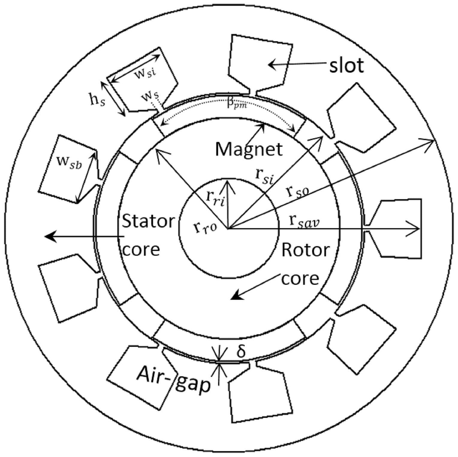
8]. The magnets are mounted on the surface of the rotor, and epoxy adhesives are used to fit them. A 2D geometry of the motor with structure-based parameters is presented in
Figure 1. The design parameters described in
Table 2 are based on [
8]. Additionally, the star connection was selected for the stator windings, and the steel-1010 core was chosen for the simulations.
Figure 2 indicates the motor simulation model, in which
Figure 2a shows the 2D CAD model, and
Figure 2b evinces the meshed SPMSM in the Ansys Maxwell environment. This tool is very useful software for analyzing the magnetic fields of electromagnetic objects such as motors, generators, coils, and all devices that work magnetically.
3. Simulation Results and Discussion
The 2D FEM-based results of the studied PMSM in both healthy and faulty states were investigated under a successive and continuous cracking and breaking of a PM. In this section, the motor is simulated. The research shows that electromagnetic variables such as current, voltage, flux, and torque are ideal indicators for detecting magnetic faults. In the case of a cracked or broken magnet, the unevenness of the air gap flux density causes some harmonics in the current of the stator windings. When there is no predicted fault in the motor, some preliminary signs of the demagnetization fault can be observed, due to magnet cracking, as the inherent faults of the motor from the signals like torque, induced voltage, and/or current. Manufacturing defects and unbalanced components of the machine can be among the inherent faults in the machine, which during the machining process or the occurrence of faults such as magnetic or short circuits can increase the fault.
Magnet structural defects occur when the motors operate under shocks and vibrations, manufacturing flaws, and fabrication failures. For this hypothetical assessment, this study evaluated four motors: (1) healthy (benchmark SPMSM) motor; (2) type A: faulty magnet cracking motor; (3) type B: faulty motor with increased magnet crack depth length; and (4) type C: faulty broken magnet. This study did not consider motor failure due to small magnet parts becoming free in the motor air gap causing winding breakdowns.
Figure 3 presents the applied methodology to conduct this study. Based on the assumption that the DC to AC inverter works ideally, the current is supplied to the motor windings. The saturation was not considered. All motor parameters are constant for comparison purposes. Next, the faulty motors were only modified through magnet geometry. The magnet geometries for each fault type (i.e., magnet structural defects) were provided by depth and width for practical designs. For each faulty motor, detailed steady state and transient FEM analyses were performed to highlight key performance parameters like torque and torque ripple. Based on driven electromagnetic data, e.g., flux linkage and inductance, the motor parameters like torque are calculated in the synchronous rotating reference frame:
where
is the motor pole number,
is the magnetic flux linkage,
and
are
-axis currents, and
and
are
-axis inductances. Magnetic flux linkage is one of the essential components of motor torque production. When the total PM flux linkage is in some way degraded due to magnet structural cracks or broken magnet pieces, motor torque will inevitably fall and several motor parameters, such as motor currents, induced voltage, noise, and vibrations, will be influenced. Such influence is evident in the frequency domain assessment of motor parameters and corresponding harmonic content.
Motor Performance Analysis Under Healthy and Magnet Damage Fault Conditions
In
Figure 2a, the healthy model without magnet structural defects (i.e., cracking fault) is presented. The performance of the healthy and faulty motors under the full load condition is discussed in this section. For the FEM model, the motor is simulated between the time of 0 ≤ t ≤ 0.4 s and the motor performance with a full load, equal by applying one constant load equal to TL = 30.57 Nm, is analyzed. The rotor speed is a constant synchronous value of 1500 rpm for steady-state simulations. The demagnetization faults caused by the faulty SPMSM, the successive crack, and eventually the broken PM were investigated. The successive PM faults were categorized based on the following three stages in this study: (A) initial crack; (B) increased crack length; and, eventually, (C) partially broken PM as given in
Table 3. To analyze the performance of the faulty conditions, these three stages were simulated. The simulations of the faulty motor according to
Table 3 were performed and analyzed for the demagnetization fault models, respectively, on one magnet of the rotor.
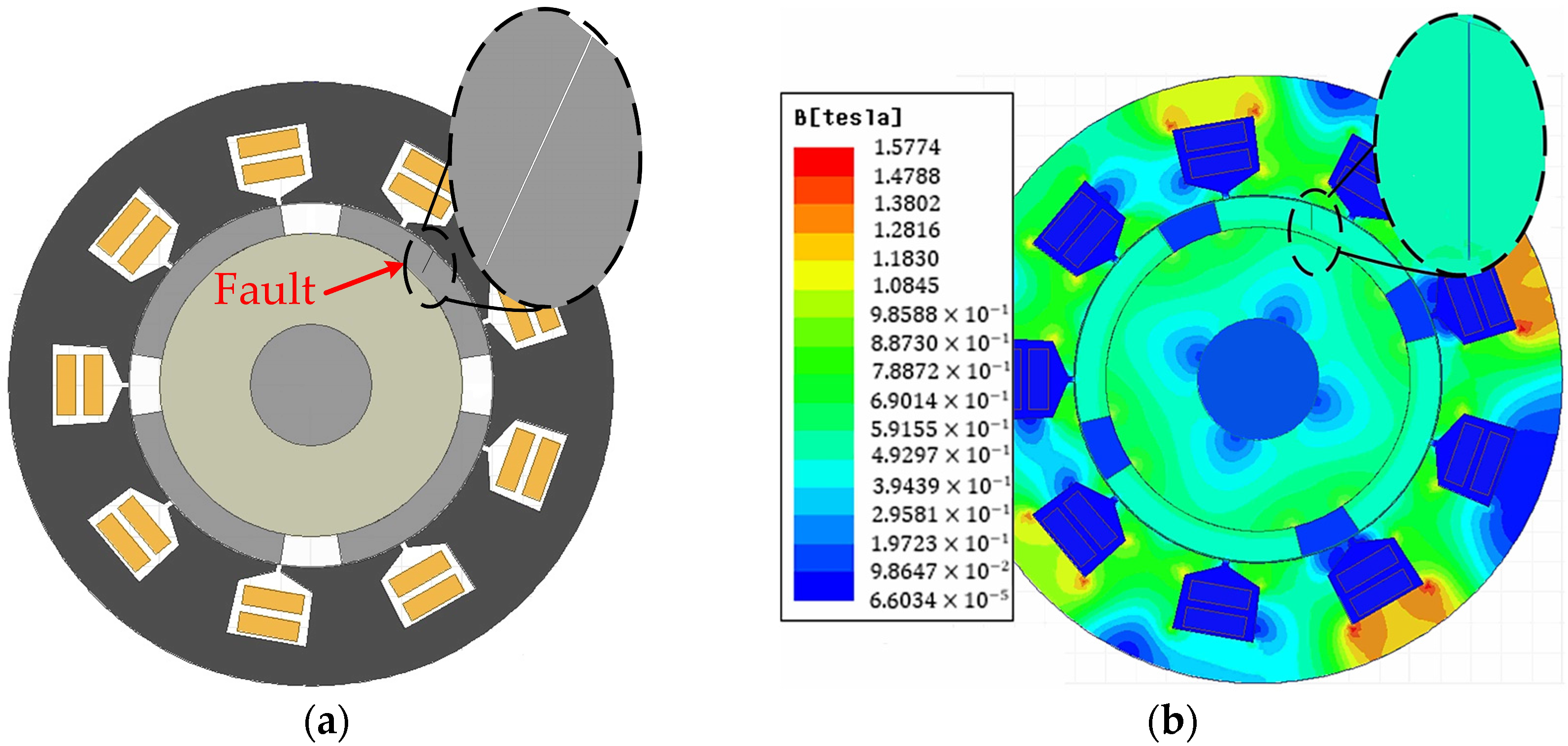
First, for the type A initial fault, one crack of a magnet in the rotor was created as a structural fault by making a crack with a width of 0.08 mm and depth of 8 mm, which is shown in
Figure 4a. The influence of such a crack was analyzed for the demagnetization fault predictions. In
Figure 4b, the impact of the crack can be observed on the magnetic flux density distribution. As can be seen, the magnetic flux density is weakened in the crack area, which indicates the reduction in the magnetic property of the PM.
Next, due to the mechanical properties of powder-based PMs, once there is a crack in the magnet, its length (severity) is likely to increase during the machine operation due to vibrations and cyclic loading (internal stress variations). In
Figure 5a, the type B fault is shown, which has gradually increased compared to the type A fault. In this stage, the depth length of the crack increased to 15 mm.
Figure 5b shows the flux density distribution. It can be seen that as the crack increases, the magnetic flux density is further weakened, which can result in a more significant reduction in the magnetic properties of the magnet and considerable impacts on motor performance.
Next, due to the brittle nature of magnet materials, cracks are likely to propagate and eventually lead to a partial breakage of the PM. In this section, the partially broken magnet caused by cracks is studied. The area of the healthy and defective magnet is 673.871 and 595.191 mm
2, respectively. The area of the removed part of the magnet is 78.68 mm
2. In
Figure 6a, fault type C, which is the most critical fault, is presented. The magnetic flux density distribution is simulated and shown in
Figure 6b. It can be seen that the magnetic flux density is weakened considerably, and its magnitude is reduced in the broken area. This result reveals that the magnetic field strength of the magnet decreased significantly.
The simulation results of the healthy and faulty motors with type A-C faults using 2D FEM are shown in
Figure 7 and
Figure 8. The simulation was carried out for 0.4 s. The magnets were magnetized radially. The PMSM driving torque was set to vary with the torque angle, which is the difference between the phase angles of the supplied and induced voltages. In terms of boundary conditions, magnetic flux density at independent and dependent boundaries match each other. The employed magnetic transient solver uses arbitrary time-varying voltage or current sources, set in an external circuit fully coupled with field quantities. The stator windings were set to stranded with a resistance of
.
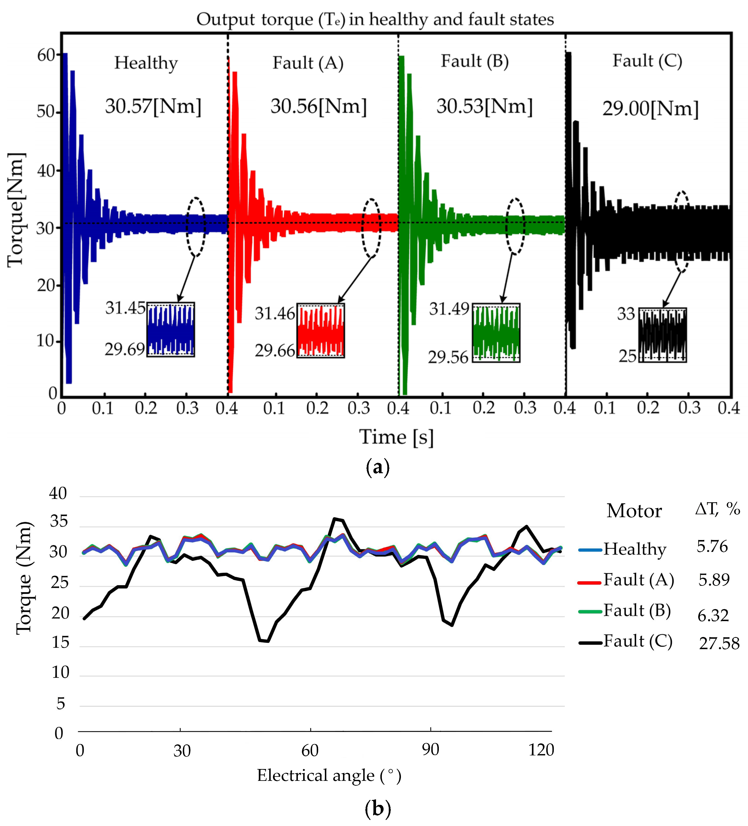
The predicted output torque of healthy and faulty motors under A-C faults is shown in
Figure 7a. The average output torque is considered equal to the load torque, TL = 30.57 Nm in blue. The torque curve under fault type A is shown in
Figure 7a in red, in which the torque ripple is almost similar to the healthy state and increased slightly. Also, the average rated load torque slightly decreased to TL = 30.56 Nm. The output torque with a type B fault is presented in
Figure 7a in green; the torque ripple in this increased fault increased slightly again from the type A fault and healthy motor. The average rated load torque decreased to TL = 30.53 Nm. The output torque with a type C fault is shown in
Figure 7a in black; the torque ripple produced in the output torque has larger values compared to the healthy motor and either of the other faults (A or B). The output torque decreased from 30.57 Nm to 29 Nm, which is more than 5%.
Figure 7b demonstrates the same output torque against the electrical angle for better visualization of magnet structural defects. The results report a critical increase in torque ripple by 27.5% and a drop in average torque by 5% only when a magnet is partially broken in the rotor.
The simulation performed in 0.4 s with full load in the healthy and type A–C faulty motor states could be observed on the torque and current in the frequency domain as demonstrated in
Figure 8a,b. The frequency spectrum of the output torque and current in the healthy and type A–C faulty motor states was computed using the fast Fourier transform (FFT), presented in
Figure 8a,b. In fault A, the crack is still small. However, the amplitude of some harmonics increased compared to the healthy FFT results in red. For example, in the torque spectrum, the amplitudes of 225, 450, 675, and 725 Hz frequencies clearly increased. Among these, the 225 and 725 Hz frequencies represented the most changes compared to other harmonic components, which can be considered more index and reliable components, and the 675 Hz frequency can be considered another component. The FFT of the stator currents in the type A fault is provided in
Figure 8b. In the current spectrum, the amplitudes of 175, 275, 400, 625, and 725 Hz frequencies had a more significant impact and created the most changes compared to other increased harmonics. Surprisingly, the 175 and 275 Hz frequencies did not appear until before the fault, which can be considered more index and reliable components in the type A fault in the current spectrum. It can also be seen in the torque spectrum that amplitudes of 225, 675, and 725 Hz frequencies in green increased again when the type B fault and the length of the crack increased, and frequencies 725 and 225 Hz showed the most significant changes during fault types A and B; thereby, these two frequencies can be considered as more indicative and reliable components in detecting fault types A and B. The frequency of 675 Hz can be considered as another component. As revealed in
Figure 8b by the harmonic content analysis of stator currents in fault type B in green, the amplitudes of frequencies 175, 275, 625, and 725 Hz drastically strengthened with the increase in fault. The amplitudes of frequencies 175 and 275 Hz, which appeared with the type A fault, also increased again. Hence, these two frequencies can be considered as more indicative and reliable components in detecting type A and type B faults in the current spectrum. It should be noted that the 625 and 725 Hz frequencies can be considered as other components. The harmonic content analysis of the torque in fault type C is shown in
Figure 8a in black. More harmonics have appeared in the faulty motor under fault type C, which indicates an increase in the severity of the demagnetization fault. This can lead to noise, vibration, harshness (NVH), and other negative effects on the motor. It is very important to detect and monitor the fault in the first place due to its minor impacts on the motor performance.
Figure 8a shows that the 75 Hz frequency did not appear in the torque spectrum until before the magnet was partially broken, which has the most influential change compared to other frequencies. The effect of this fault on the sidebands of the third and fourth harmonics, respectively, was observed in the spectrum of the torque and current. The 175 Hz harmonic can also be defined as significant, which could be introduced as other fault indices. However, the change in behavior of these two components is like other harmonics during faults, in which the 75 Hz frequency is the most prominent and therefore the most impactful and reliable metric for the detection of fault type C. The harmonic content analysis of the stator currents under the C fault state is shown in
Figure 8b in black. As can be seen, the harmonic components increased when the PM was partially broken (fault type C). The 25 Hz and 125 Hz frequencies did not appear in the spectrum of the stator currents before the type C fault, yet they can be seen with the impact created in this type of fault. These two components in the frequency spectrum of stator currents cause the most changes compared to other components. The behavior of other components was similar with increasing cracks: the 25 Hz frequency had the most impact and was the most dominant and reliable component for the diagnosing of fault type C using the stator currents. The 125 Hz frequency can be considered another index for the detection of the partially broken magnet fault.
The comparison of the amplitudes of harmonics appearing in the spectrum of the output torque and stator currents in healthy and faulty motor states is displayed in
Figure 9 and
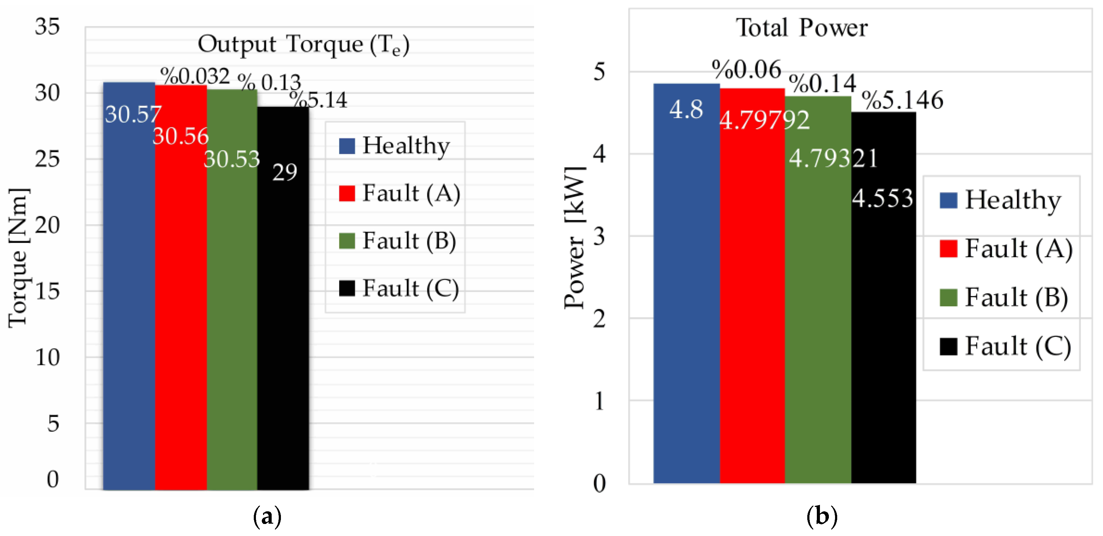
Figure 10. Reducing the output torque reduces the total rated power of the motor. The output power was simulated based on the rated load. In
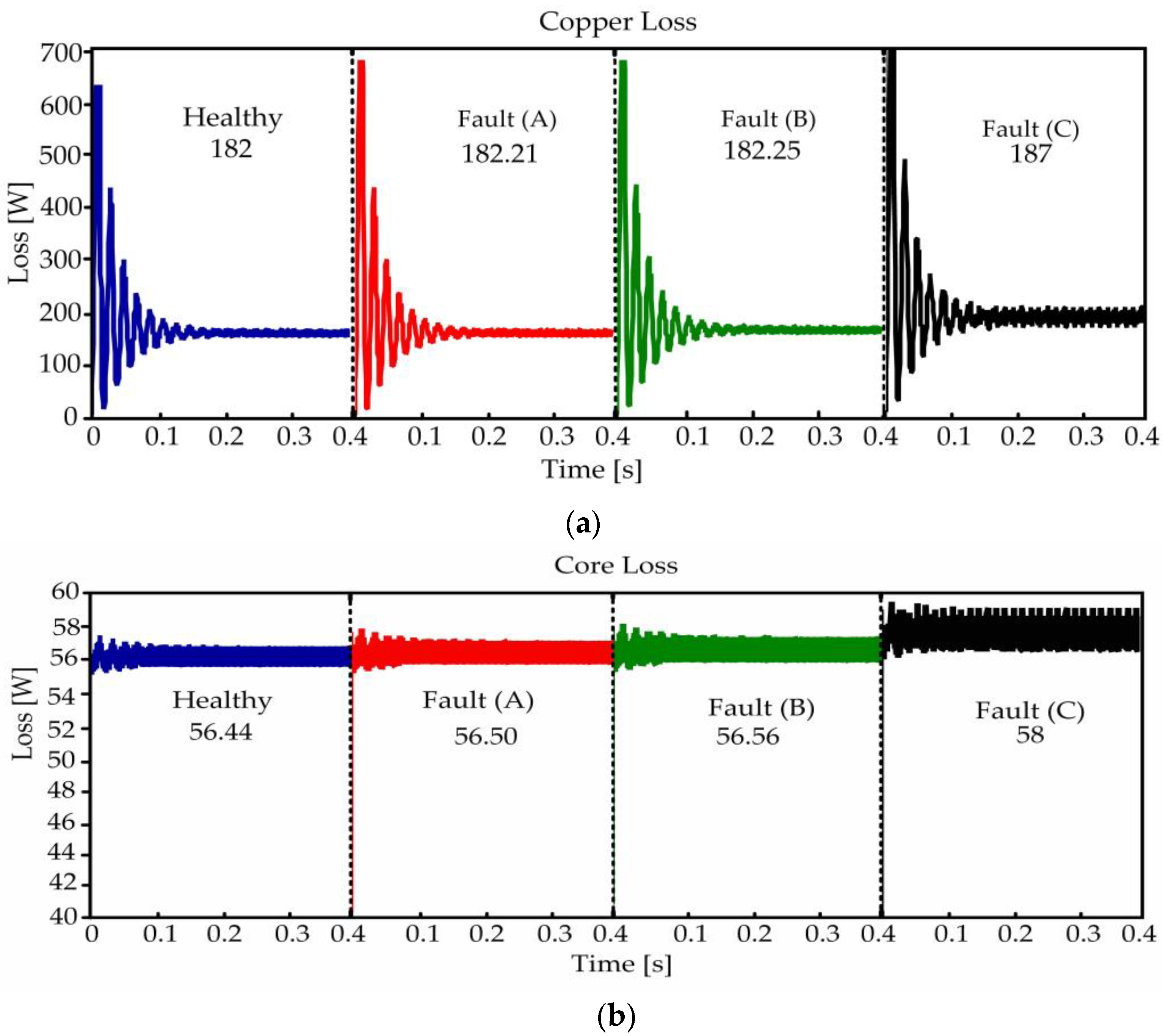
Figure 11a,b, the changes in the output torque and total power of the healthy and faulty motors under faults A–C are demonstrated. The results confirm cracks (i.e., types A and B) due to the decrease in torque, respectively, from 30.57 Nm to 30.56 and 30.53 Nm. These magnet structural defects can reduce the torque by less than 0.2% and result in the partial failure of the magnet (i.e., type C) due to the decrease in torque from 30.57 to 29 Nm. It can reduce the torque by more than 5%. Therefore, these defects can result in less than 2% and over 5% performance prediction errors (i.e., torque and total loss), respectively.
5. Additional Analysis and Simulation of the Faulty Motor Under Different Crack Fault Conditions
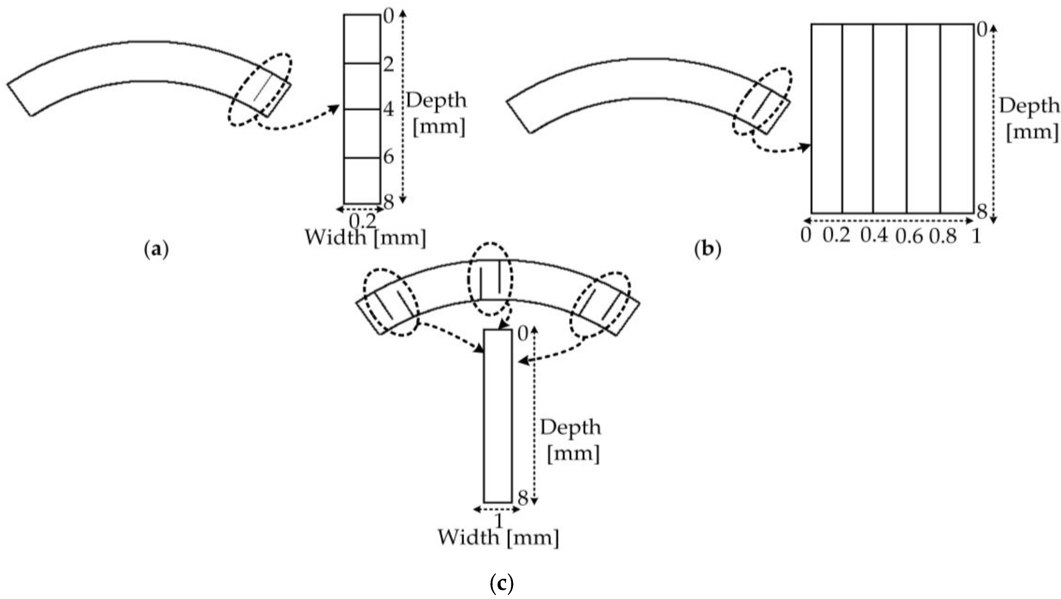
In order to analyze the accuracy of the proposed method of crack fault and crack propagation, various cracks with different depths, widths, and locations were analyzed and simulated as shown in
Figure 14a–c. To assess the fault, first, a crack with a width of 0.2 mm and a depth of 2 mm is created in the corner of the magnet. Then, the depth of the crack is increased by 2 mm in each step up to a depth of 8 mm, which is shown in
Figure 14a. In the next step, the width of the crack with a depth of 8 mm is analyzed for an increase of 0.2 mm in each step up to a width of 1 mm, which is shown in
Figure 14b. In the next step, six cracks with a depth of 8 mm and a width of 1 mm are created on the magnet in different directions as shown in
Figure 14c. With the diffusion and addition of each crack, the results are simulated and analyzed. The results of the simulation were analyzed in the domain of frequency spectrum on the output torque, stator currents, torque ripple, average output torque, and rated power of the motor in healthy and faulty conditions. The simulation of the first crack according to
Figure 15a was conducted using Ansys Maxwell, which can be seen in
Figure 15a.
Figure 15b,c indicate the frequency spectrum of the output torque and stator current, respectively. As can be seen in
Figure 15b, the amplitude of the frequency components of 225, 450, 675, and 725 Hz in the torque spectrum, which were introduced as fault indicators, increased with the increase in crack length.
In
Figure 15c, the amplitude of the harmonic components of 175, 275, 400, 625, and 725 Hz, which were introduced as fault indicators in the analysis of the harmonic content of the stator current, increased during the increase in the crack depth.
Table 5 shows the comparison of the results of increasing the crack depth on the average output torque, torque ripple, and rated power in healthy and defective conditions. In the first crack, the average torque and power decreased from 30.57 Nm to 30.48 Nm and 4.8 kW to 4.7853 kW, which decreased by 0.3%. Also, torque ripple from 5.76% to 6.5% showed an increase of 12.84%. In
Figure 16a,b, the results of the next stage simulation of the crack fault are shown according to
Figure 14b.
Figure 16a shows the crack model simulated using Ansys Maxwell.
Figure 16a,b show the spectrum analysis of the harmonic content of the output torque and stator currents, respectively. In
Figure 16, the amplitudes of frequency components are analyzed using 2D FEM simulations. A systematic increase in magnet structural defect (i.e., fault A) is introduced to examine the impact caused by magnet cracks from 2 to 8 mm. In
Figure 16a, the FFT shows that the frequency components of 225, 450, 675, and 725 Hz have adverse effects on output torque when the length of the crack increases. Such undesirable outcomes have also been seen for the 175, 275, 400, 625, and 725 Hz frequency components of stator current, which increased more than the other components when compared to the healthy motor in
Figure 16b. Relatedly, these effects can be seen in
Figure 17 and
Figure 18 when the width of the crack and cracks in different locations arise in structural defects introduced by faults B and C. As can be seen in
Figure 17a, in the torque spectrum at this stage of the fault, the introduced fault indicators such as the frequency components of 225, 450, 675, and 725 Hz increased with the increase in the crack width and showed more changes compared to other frequencies. In
Figure 17b, in the spectrum of the current amplitude, the component frequencies of 175, 275, 400, 625, and 725 Hz increased more than the previous faults with the increase in the crack width.
Table 6 compares the results of the changes in crack width in healthy and defective engine conditions. The average output torque and rated power decreased by 0.85% from 30.57 Nm and 4.8 kW to 30.31 Nm and 4.7586 kW, respectively, with the increase in crack width. The torque ripple showed a decrease of 17.88% compared to the healthy state.
Figure 18 exhibits the simulation of crack propagation produced using Ansys Maxwell.
Figure 18 b presents the frequency spectrum of the output torque in the healthy and fault states.
Table 5,
Table 6 and
Table 7 report the comparison of the overall results of the changes in crack growth and propagation in the healthy and defective states (i.e., faults A to C). The results show that the average output torque and rated power decreased by more than 5% from 30.57 Nm to 28.9 Nm and 4.8 kW to 4.537 kW, respectively, with crack propagation. As shown in
Table 7, the torque ripple interestingly increased from 5.76% to 13.63% compared to the healthy state and increased by more than 2 equal, which can cause motor noise and vibration. The results show the correctness of the indicators introduced in the faults. Therefore, detecting and identifying even a small error in the first place can prevent more errors and irreparable damages.
