
Changes in Material Behavior according to the Amount of Recycled Magnetic Materials in Polymer-Bonded Magnets Based on Thermoplastics


Institute of Polymer Technology, Friedrich-Alexander-Universität Erlangen-Nürnberg, 91058 Erlangen, Germany
*
Author to whom correspondence should be addressed.
Magnetism 2024, 4(1), 1-23; https://doi.org/10.3390/magnetism4010001
Submission received: 22 September 2023
/
Revised: 18 December 2023
/
Accepted: 25 December 2023
/
Published: 15 January 2024
Abstract
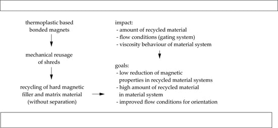
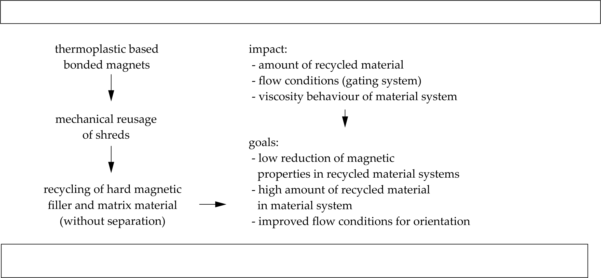
:The applications of polymer-bonded magnets are increasing within drive technology mostly because of new concepts concerning the magnetic excitation of direct current (DC) or synchronous machines. To satisfy this rising demand for hard magnetic filler particles—mainly rare earth materials—in polymer-bonded magnets, a recycling strategy for thermoplastic-based bonded magnets has to be found that can be applied to polymer-bonded magnets. The most important factor for the recycling strategy is the filler material, especially when using rare earth materials, as those particles are associated with limited resources and high costs. However, thermoplastic-based bonded magnets reveal the opportunity to reuse the compound material system without separation of the filler from the matrix. Most known recycling strategies focus on sintered magnets, which leads to highly limited knowledge in terms of strategies for recycling bonded magnets. This paper illustrates the impact of different amounts of recycling material within the material system on material behavior and magnetic properties that can be achieved by taking different flow conditions and varying gating systems into account. The recycled material is generated by the mechanical reuse of shreds. We found that a supporting effect can be achieved with up to 50% recycled material in the material system, which leads to only minimal changes in the material’s behavior. Furthermore, changes in magnetic properties in terms of recycled material are affected by the gating system. To reduce the reduction in magnetic properties, the number of pin points should be as low as possible, and they should located in the middle. The filler orientation of the recycled material is minimally influenced by the outer magnetic field and, therefore, mainly follows the flow conditions. These flow conditions are likely to be affected by elastic flow proportions with increasing amounts of recycled material.
1. Introduction
1.1. Magnetic Properties
The basis of magnetic properties—the smallest magnetic unit of a solid—can be described by a single electron and its magnetic moment, which is generated by the rotation of the electron around its axis or the proton [1]. Ferromagnetic materials are the largest group among magnetic behavior types, corresponding to a permanent magnetic moment without an outer magnetic field as long as the temperature is below the Curie temperature (TC). Hard magnets are a group of materials that exhibit ferromagnetic behavior with a characteristically high resistance to demagnetization [2].
Within hard magnetic fillers, two main groups have to be distinguished: ceramic materials such as strontium–ferrite–oxide (SrFeO) and rare earth materials such as neodymium–iron–boron (NdFeB) [3]. The magnetic properties of the application are highly affected by the filler type, resulting in not only different intrinsic magnetic properties, geometries and particle sizes but also different flow conditions, requiring outer magnetic field strengths for orientation and magnetization, as well as the possibility of generating agglomerates. Furthermore, each filler type can exhibit isotropic or anisotropic behavior relative to the crystal structure and the fabrication process [4]. As isotropic fillers are orientated randomly, whereas anisotropic fillers reveal a preferred direction through the orientation, the magnetic properties of anisotropic fillers can realize up to 85% of the saturation flux density (BS), whereas isotropic fillers account for only 50%. [5] After the orientation is the change in the geometric position of the filler; the potential of both types can only be used if the viscosity is low enough such that the movability within the matrix can be determined [6]. The orientation of hard magnetic fillers is determined through the integration of an outer magnetic field within the fabrication process, which can only take place when the movability of the fillers is high enough. Magnetization can take place during the fabrication process, as well as after this step, as it does not require a geometrical change in position but a change at the atomic level [7].
Polymer-bonded magnets are composed of at least a matrix material and a hard magnetic filler. Furthermore, the application of additives is possible to improve, for example, the flowability or the adherence between the two main components. The matrix material defines both the possible fabrication method and the total filler content. Therefore, injection-molded magnets are mostly based on a thermoplastic-based matrix with a limited filler grade of 65% of the volume [8]. Typically, polyamides (PA) such as PA12 or polyphenylene sulfide (PPS) are used for higher thermal resistance in a thermoplastic matrix [9]. On the other hand, the matrix of thermosets in bonded magnets is primarily manufactured in a pressing process [10] with a maximum filler grade of 85% of the volume. Therefore, it is likely that the magnetic properties of pressed magnets are increased relative to those of thermoset-based magnets [11].
1.2. Urgent Requirement of Recycling Strategies for Polymer-Bonded Magnets
Relative to polymer-bonded magnets, rare earth materials are a limited resource and are, therefore, the focus of the recycling strategies. Furthermore, NdFeB—as the typical representative of rare earth fillers—is the third leading rare earth material and, among permanent magnets, the strongest known material at the moment [12]. A proportion of 90% of the total worldwide production of NdFeB is used to produce permanent magnets [13]. Furthermore, a significant amount of NdFeB is applied to drive technology. Concerning the worldwide utilized NdFeB, 59% and 89% were applied in 2012 in 2018, respectively, in the electric motor industry, e-mobility and wind energy applications. It is assumed that such applications will account for up to 95% of NdFeB resources by 2030, especially given the significantly increasing demand expected in the e-mobility industry in the coming years [14]. However, applications involving the use of ceramic materials like SrFeO as the hard magnetic filler have increased in recent years as well. This goes along with a changed view of aspects such as resource-saving behavior and environmental protection [15]. Nevertheless, only 6% of permanent magnets are polymer-bonded magnets, which goes along with the fact that polymer-bonded magnet fabrication technology for driving applications is in the early stages of development [14].
Preliminary investigations of the application of polymer-bonded magnets to drive technology—so far based on thermoplastics—show the successful implementation of polymer-bonded magnets in synchronous reluctance motors in general. However, thermoplastic-based matrices are associated with a lack of chemical permanence and thermal resistance [16]. In addition to drive technology, polymer-bonded magnets have also been applied in sensors, for example, to detect motion or to determine the positions of objects using a Hall sensor [8]. Applications of polymer-bonded magnets to drive technology require a multipolar and complex magnetic field structure, which can only be fabricated by the injection molding process—not only because of process conditions but also in terms of financial and economic aspects. This method defines a thermoplastic matrix material at the moment, as—so far—thermoset-based polymer-bonded magnets cannot be fabricated by injection molding [17]. It has to be taken into account that the matrix material defines material behavior and processing conditions as well as the properties of the application. For example, thermoplastics exhibit lower thermal and chemical resistances than thermosets [18], which limits their possible applications to drive technology at the moment.
After the general proof that these new concepts can be implemented and subsequently highly change the construction of drive technologies, polymer-bonded magnets play an important role when it comes to finding new strategies to meet the actual demand in drive technologies. This is mainly based on the possibility of realizing multipolar and complex magnetic field structures in the injection molding process. The new concepts allow more efficient usage of the magnetic potential of the hard magnetic filler and its properties so that SrFeO is more likely to be used even though it has less initial magnetic properties compared to NdFeB. Therefore, the recycling strategies have to be focused on these upcoming applications in terms of polymer-bonded magnets—both for NdFeB and SrFeO.
1.3. Recycling Possibilities of Polymer-Bonded Magnets
To meet the demand for hard magnetic fillers, especially in applications of the drive technology, the general amount of material which is needed for the application can be reduced due to new concepts, which allow less material impact by similar or even higher application properties [19]. Furthermore, limited resources like NdFeB can be substituted following three different strategies: substantial (chemical elements are exchanged, for example, neodymium for praseodymium), material (different material system with similar properties) or functional (new technology) substitution [14].
The recycling of polymer-bonded magnets is the third possibility to ensure that the rising demand is met. It has to be distinguished between different target functions. The recycling strategies can be focused on the recovery of the pure matrix material, the pure hard magnetic particles or both materials. In terms of thermoplastic-based polymer-bonded magnets, the focus always lies on the hard magnetic filler, but thermoplastics allow the recycling of both materials simultaneously by mechanically producing and reusing shreds. However, multiple fusions can cause aging within thermoplastics. Another possibility is the thermal recycling or the reduction into monomers by applying the solvolysis method. To ensure a successful implementation of recycling strategies, the following aspects have to be ensured: a closed-loop economy, a return and a disassembly possibility. Therefore, a collection and segmentation system has to be established as well while speaking of recycling strategies for polymer-bonded magnets [20].
So far, the focus of recycling strategies in terms of permanent magnets lies on sintered ones. For example, [21] indicates a chemical route by metallurgical treatment in comparison to different other process routes to reach the best results in terms of the reutilization of sintered permanent magnets in electromotors. A theoretical method of recycling polymer-bonded magnets was depicted in [22], where the matrix material is removed through a solvent and the extracted filler is used again. However, this method has not been adopted for several different applications. The authors of [23] show a possible route of recycling polymer-bonded magnets based on thermoplastics by reusing shreds. Here, 100% recycled material was used, which led to a reduction in the magnetic properties by 20%. Furthermore, no investigations in terms of the gating system and with that changing flow conditions were conducted. So far, only a few investigations have been completed in terms of recycling polymer-bonded magnets, and none of them dealt with the question of how the material behavior is affected by different amounts of recycled material as well as the flow conditions by changing the gating systems.
Therefore, the aim of this paper was the generation of a general understanding of the material behavior within material systems with varying amounts of recycled material and the transfer to the test samples in terms of changing the gating system and with that flow conditions. The results should be transferred to define possible material systems and flow conditions relative to specifications of the deviation in terms of the magnetic properties.
2. Materials and Methods
2.1. Material
The experiments were conducted with two materials based on the thermoplastic matrix polyamide 12 (PA12). The hard magnetic fillers in the material systems have to be divided between the anisotropic strontium–ferrite–oxide (SrFeO) and the isotropic neodymium–iron–boron (NdFeB) with a constant filler grade of about 65 vol.-%. The exact amount of the fillers is a business secret and cannot be fully analyzed, as it is unknown whether other additives are added or not. The chosen materials were a commercial compound system of the type HM-1222H in terms of SrFeO and RNI-25LF2 in terms of NdFeB (Dowa Holdings Co., Ltd., Tokyo, Japan). As the paper investigates a recycling strategy of thermoplastic-based polymer-bonded magnets, the starting material was defined as a material type, which can be commonly obtained.
The mechanical reusage of the shreds was held in different proportions compared to the unrecycled, new material. The amount of recycled material (exact definition of recycled material in Section 2.2) differed between 0 and 100 vol.-% in steps of 25 vol.-%. In the case of 0 vol.-% recycled material, the commercial material system in the new and unused stadium was processed, whereas in terms of 100 vol.-% recycled material, no new material was part of the material system.
Table 1 presents the density ρ and the remanence BR of the two material types in its unrecycled stadium regarding the manufacturer specifications as well as the amount of the recycled material in the different material systems. Furthermore, Figure 1 shows the route of the dynamic scanning calorimetry (DSC) measurement of the two commercial material systems. In terms of the hard magnetic filler SrFeO, the specific enthalpy of both peaks is lower compared to NdFeB. Furthermore, the cooling peak is shifted to lower temperatures for SrFeO compared to NdFeB.
2.2. Fabrication of the Test Specimens
Using a Demag Ergotech 25/280-80 injection-molding machine (Sumitomo (SHI) Demag Plastics Machinery GmbH, Schwaig by Nuremberg, Germany) with a screw diameter of 18 mm, the test samples were fabricated pressure controlled. The circular test samples revealed an outer diameter of 30.6 mm, a breadth of 4 mm and a width of 5 mm. The outer magnetic field was placed radially around the cavity with 12 poles.
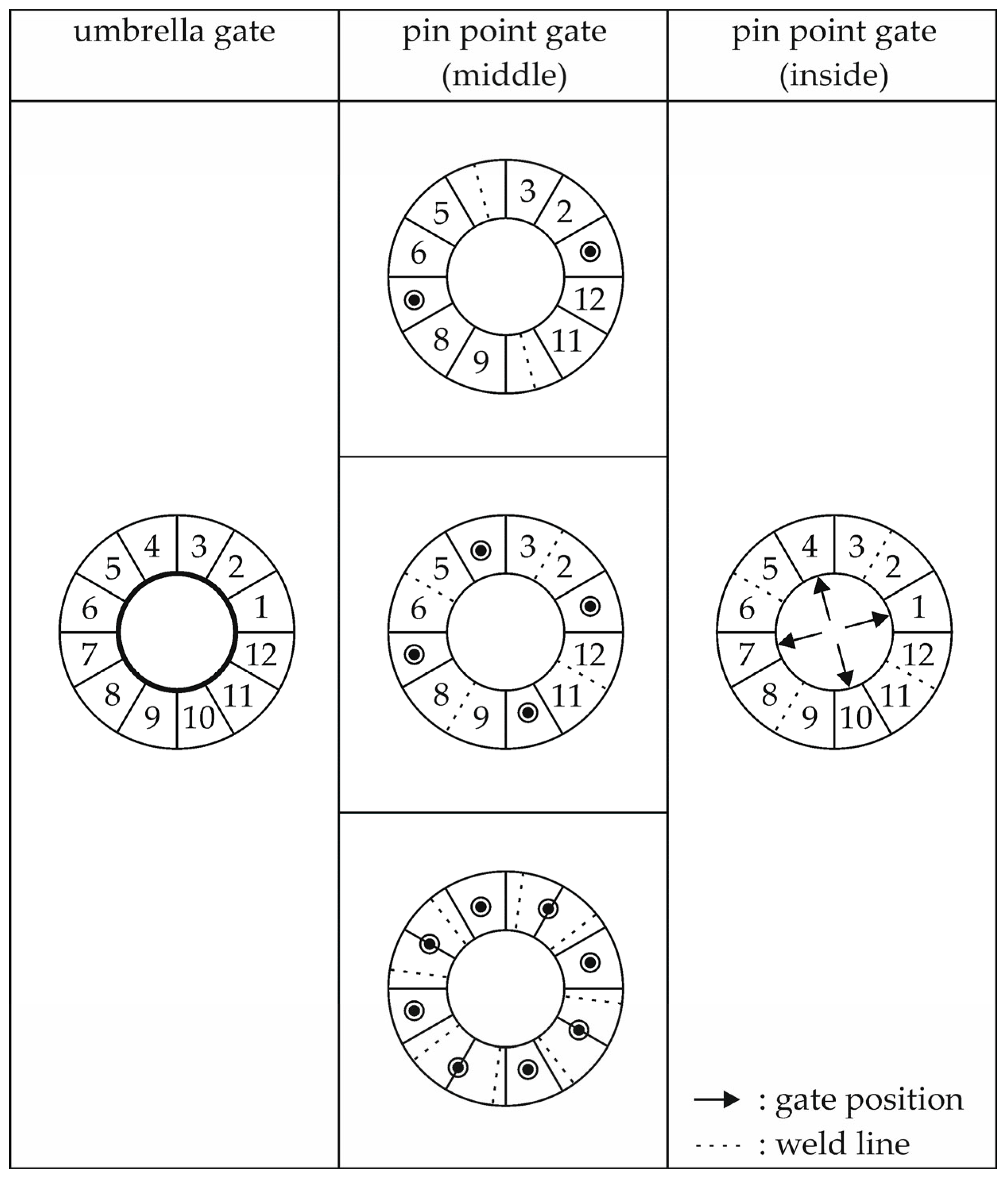
Within the experiments, different gating systems were used to change the flow conditions throughout the filling of the cavity. In addition to an umbrella gate, a two, four and eight-pin-point gating system was used, which was located in the middle of the ring segment diameter in the middle of the pole. Furthermore, a four-pin-point gate was considered, which was placed in the middle of the pole on the inner side of the ring. Figure 2 reveals the position of the different gating systems as well as the position of the weld line according to the filling conditions.
The processing parameters were set as shown in Table 2 and kept as constant as possible throughout the different material systems and gating systems. The changeover point had to be adopted in terms of the different material and gating systems to ensure a full filling of the cavity. With the increasing amount of recycled material in the material system as well as an increasing amount of pin points, the pressure of the changeover point had to be increased. Before the fabrication, the material was dried in a convection oven at 80 °C for four hours.
To ensure the fabrication of recycled material, the new and unrecycled material was extruded within the injection-molding machine. This extruded material was regranulated in a mill. This material will be called recycled material in the ongoing manuscript. In a manual mixing process, the amount of the new and the recycled material was combined to ensure the material systems with the different amounts of recycling material. Afterward, the materials systems were dried again in a convection oven at 80 °C for four hours before the fabrication.
The ring samples were magnetized in the tool during the injection molding; afterwards, mechanical reuse requires a demagnetization of the samples. This is an expensive process, so the first attempts for the strategy were held with extruded material, where demagnetization is not needed.
2.3. Characterization
2.3.1. Differential Scanning Calorimetry (DSC) following DIN EN ISO 11357
To define the heating and cooling behavior of the thermoplastic-based compound (new material and different amounts of recycled material) and especially to analyze changes in the material behavior due to aging effects, DSC measurements were carried out based on the DIN EN ISO 11357 [24] standard. Therefore, pellets with a weight of about 10 mg were used on the DSC of TA-Instruments (New Castle, DE, USA).
The material was tempered at 80 °C for 15 min. Afterwards, the material is heated from 0 to 220 °C with a constant rate of 20 K per minute in the first heating cycle. This step was followed by an isothermal hold of 0.5 min and the cooling of the material down to 0 °C at the same rate. Again, the temperature was held isothermal for 5 min before being reheated to 220 °C in the second heating cycle. To characterize the material behavior, the following indicators were used: the melting peak temperature (the second heating), the crystallization peak temperature, the general route and the shape of the peak.
In general, chemical aging effects are portrayed by a shift of the crystallization peak toward lower temperatures as well as a shift of the melting peak during the second heating cycle again toward lower temperatures. Furthermore, the melting peak could shape a double peak and could reveal a lower enthalpy [25].
2.3.2. Thermogravimetric Analysis (TGA) following DIN EN ISO 11358
A thermogravimetric analysis (TGA) was realized based on the DIN EN ISO 11358 [26] standard (type: TGA–Q 5000, TA Instruments, New Castle, DE, USA) to evaluate the change in the mass as an indicator of aging. The effect of aging would lead to a shift of the change in the mass toward lower temperatures or shorter times [25].
A dynamic measurement was realized under a nitrogen atmosphere after the material was pre-dried at 80 °C for 20 min. After that, the change in the mass was determined for each material system with the different amounts of recycling material while the temperature was raised between 50 and 800 °C with a constant rate of 20 K per minute. Furthermore, an isothermal measurement was held again under a nitrogen atmosphere at the temperature of 385 °C for 90 min.
2.3.3. Particle Size Distribution
Based on the residue of the TGA measurements, an optical camera with static image analysis (Morphology G3s, Malvern Panalytical GmbH, Kassel, Germany) portrayed the particle size distribution of the recycled filler materials. Within the measurement, the volume of filler samples was 5 mm3, and up to 80,000 particles were counted.
Furthermore, a scanning electron microscope (Gemini Ultra-Plus; manufacturer: Carl Zeiss AG, Oberkochen, Germany) was used to portray the size and geometry of the recycled filler material in comparison to the new filler material.
2.3.4. Determination of the Viscosity Behavior Based on a Rotational Viscometer
To analyze the viscosity behavior of the material, which is fabricated in the injection-molding process, the high-pressure capillary rheometer is more suitable due to the high-end process like shear rates compared to the rotational viscometer. However, highly filled materials tend to particle interaction and blocking within the analysis of the viscosity in a high-pressure capillary rheometer, especially with high degrees of recycled material. Therefore, the viscosity behavior was defined using a rotational viscometer (type: Discovery Hybrid Rheometer 2, TA Instruments, New Castle, DE, USA) based on two plates with a shearing load. Within the test setting, the shear rate was rather low compared to the actual process conditions. After the setting was kept constant for each material system, a comparison of the materials within this setting is said to be appropriate. Furthermore, the low shear rates lead to more precise results due to the high sensitivity of the measurement equipment.
To analyze the viscosity behavior, two measurement routes were taken. First, the complex viscosity η was defined at a constant setting of a temperature of 190 °C, an axial force of 5 N with 1 Hz frequency and an oscillation strain of 102. Within highly filled material systems, the oscillation is more suitable compared to the rotation, as the fillers become orientated homogenously in one direction, and it prevents the measuring plate from just sliding on the rough surface of the fillers.
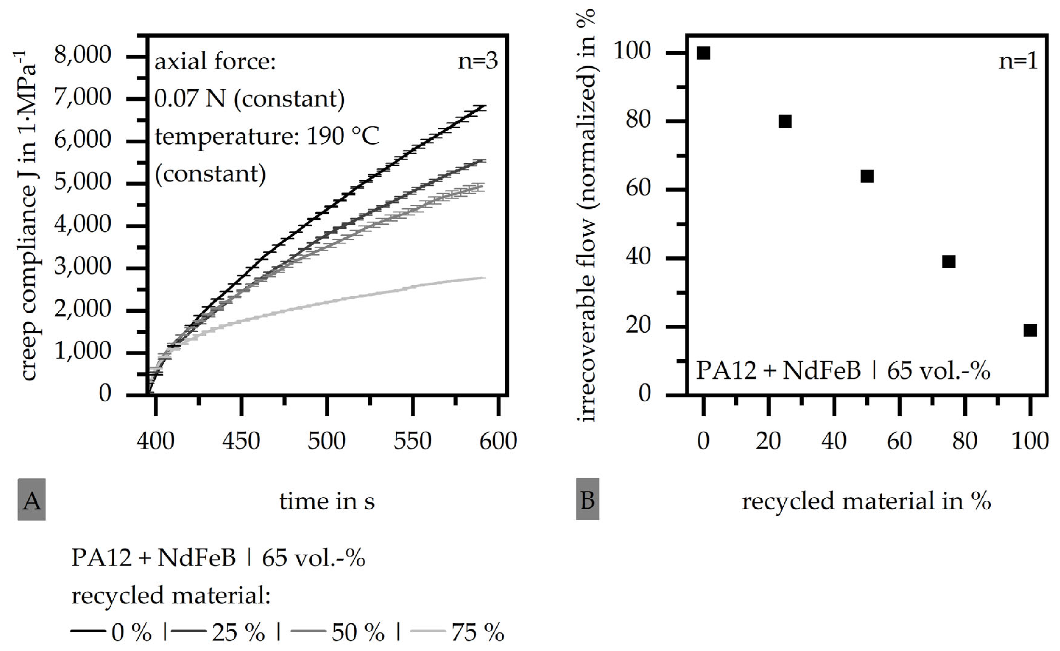
Within the second measuring route, the elastic and viscous flow amounts were defined by analyzing the creep compliance J. Therefore, a constant and low axial force of 0.07 N was applied to the test samples at a constant temperature of 190 °C, and the creep compliance J was measured. Setting a tangent to the slope of the high creep compliance J, the intersection with the axis of ordinates was determined, which reveals the elastic amount of the creep compliance JE according to Figure 3. The difference between the maximum of J and JE reveals the viscous amount JV and is also called the irrecoverable flow. [27]. Figure 3 depicts the route of a creep compliance J relative to the time schematically concerning the reached amount of JE and the maximum of J—called Jmax.
2.3.5. Magnetic Properties
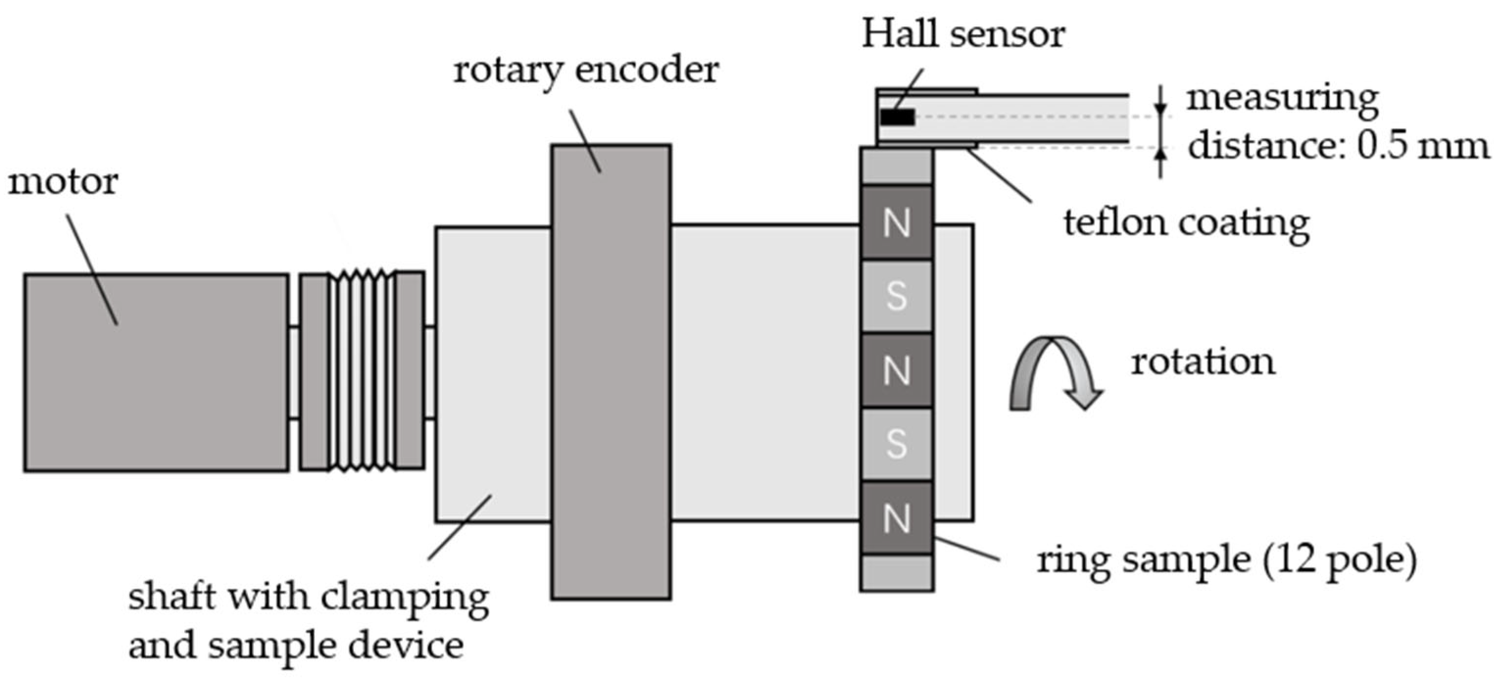
A specific test rig, shown schematically in Figure 4, allowed the determination of the magnetic flux density. Here, the circular test sample was picked up via a clamping device. A hall sensor allowed the tracking of the flux density relative to the rotation angle of the rotor. The angle was received simultaneously using a rotary encoder from Heidenhain GmbH (Traunreut, Germany). The shaft was driven by a motor with an adjustable speed and number of revolutions or running times so that the route of the magnetic flux density was determined for 360° or any multiple. The analyses of the magnetic properties were conducted at room temperature.
The route of the magnetic flux density should ideally reveal a sinus wave. Concerning the different gating systems, so-called characteristic poles were defined, where pole A reveals the pole of the gate and—for example—in the case of a two-pin-point gate, pole D is located at the weld line. In the case of the eight-pin-point gate system, there is singularity regarding the characteristic poles. In that case, every second gate is located on the pole division instead of the middle of the pole. With that, the weld line is located in between the middle of the pole and the pole division and therefore not at the position of the maximum. Those two special positions are defined with the characteristic pole b In the case of the weld line and c in the case of the second gate allocation. Figure 5 reveals an overview of the characteristic poles concerning the different gating systems. The maximum of the magnetic flux density at each characteristic pole was determined. Furthermore, the angle between two zero transitions was defined concerning the characteristic poles to analyze the pole accuracy. In terms of 12 poles, each pole width should exhibit 30°.
2.3.6. Filler Orientation
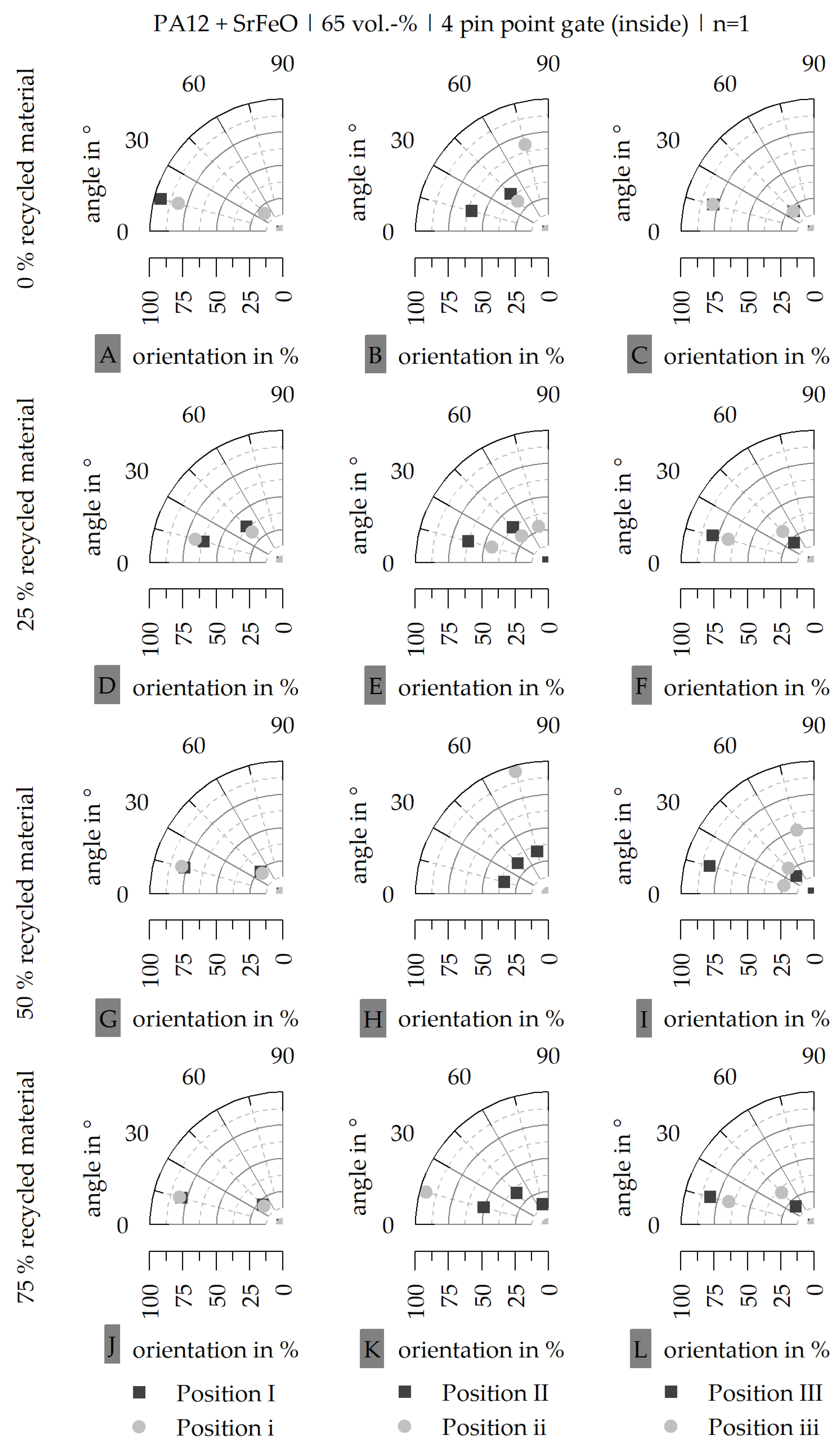
To define the filler orientation, the samples have to be prepared in the first step. Therefore, half of the circular test samples were embedded in cold-curing epoxy resin (type: Epofix, Struers GmbH, Ottensoos, Germany). Afterwards, the samples were divided in the center by a water-cooled saw to ensure a minimal temperature input. This preparation allowed the microscopic examinations in the center of the specimen width, which means that the images were taken perpendicular to the expected long axis of the filler. The specimens were polished before the images were taken by a stereo microscope (type: Axio Zoom. V16, Carl Zeiss AG, Oberkochen, Germany). The orientation was defined at different positions along pole A (gating position) and pole B for each circular test specimen. Afterwards, a gray scale threshold analysis was used to separate the matrix and the hardmagnetic fillers to evaluate the orientation of the fillers. Figure 6 shows the different preparation steps of the samples as well as the expected orientation. In both poles and the pole division, the orientation was analyzed near the edge of the sample (position I|II|III) and in the middle of the sample diameter (position i|ii|iii). Furthermore, position iv depicts the orientation at the middle of the sample diameter in between the middle of the pole and the pole division. Based on the current research data [28], the orientation in the edge of the sample is isotropic due to the fast cooling outer region of the melt. Therefore, no preferred orientation is expected in positions I to III. The orientation in the middle of the sample diameter follows the outer magnetic field.
3. Results and Discussion
3.1. Differential Scanning Calorimetry (DSC) following DIN EN ISO 11357
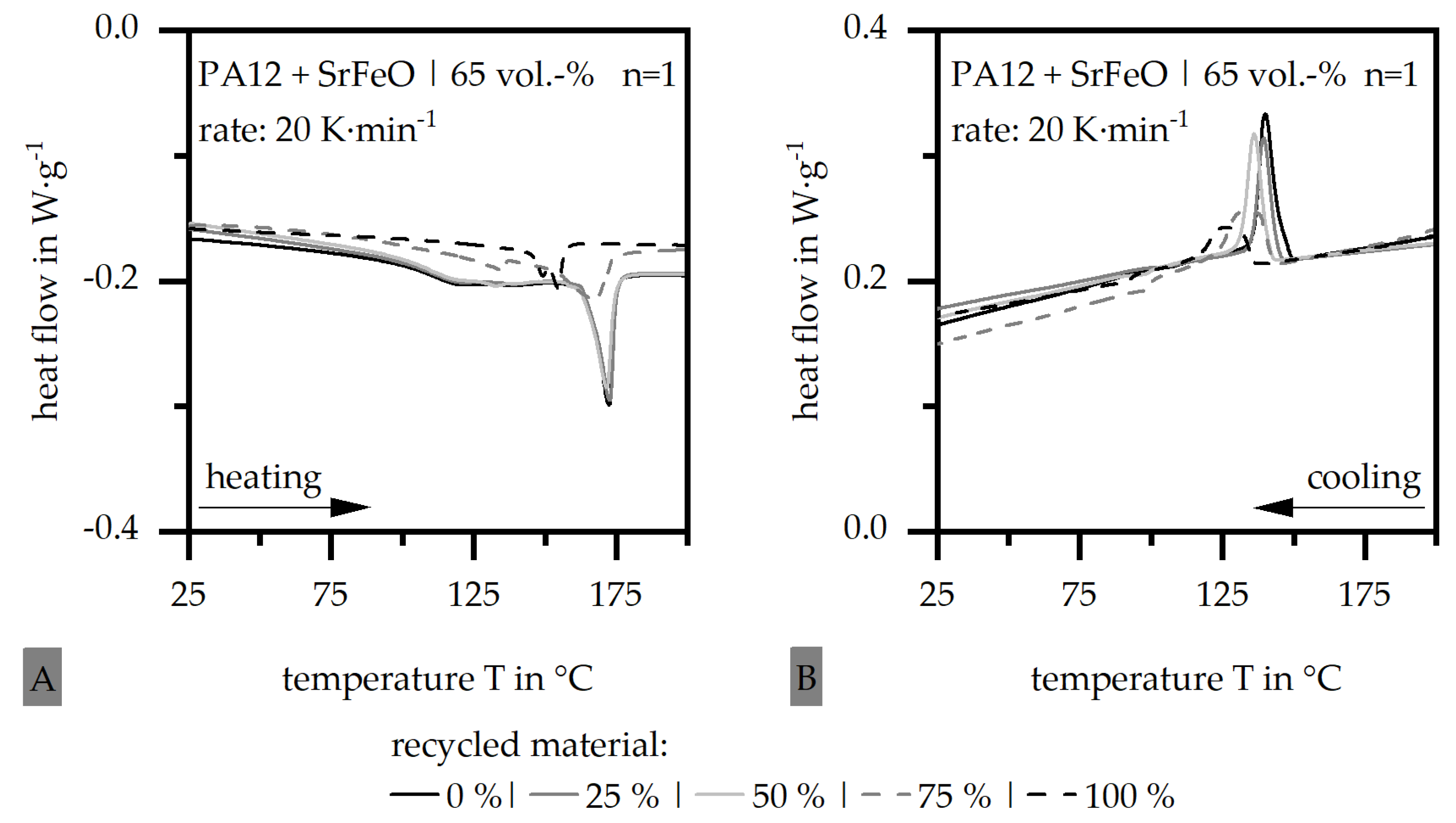
The route of the DSC measurement concerning the amount of recycled material is shown in Figure 7 for the hard magnetic filler SrFeO and in Figure 8 for NdFeB. In each figure, A depicts the route of the second heating and B depicts the route of the cooling. Figure 7A reveals a shift of melting peak with the amount of recycled material greater than 50% toward lower temperatures and a reduction in the enthalpy. If the recycled material reaches 100%, a double peak is shown. Furthermore, Figure 7B depicts a shift of the crystallization peak toward lower temperatures. This shift already starts with a low amount of recycled material, but a significant reduction in the enthalpy can be seen only with an amount greater than 50%. With that, chemical aging is likely to occur with an amount of recycled material greater than 50%. If the amount of the recycled material is under 50% or 50%, it can be assumed that the new material has enough supporting effect on the recycled material. With that, the change in the route of the DSC measurement and the kinetic behavior is similar between the new material and the mixed one with up to 50% recycled material.
A similar behavior can be seen in terms of Figure 8, where the melting point of the second heating and the crystallization peak of the cooling is already slightly shifted toward lower temperatures with a small amount of the recycled material. A significant reduction in the temperature and the enthalpy is only portrayed for the 100% recycled material. Furthermore, the general enthalpy level is higher for the hard magnetic filler NdFeB compared to SrFeO. As the filler itself does not take part in the reaction and phase transition, this difference is mainly due to the heat capacity and the thermal conductivity of the two filler systems. SrFeO depicts a heat capacity c of 0.64 J∙g−1∙K−1 and a thermal conductivity λ of 2.3 W∙m−1∙K−1, whereas NdFeB has a heat capacity of 0.42 J∙g−1∙K−1 and a thermal conductivity λ of 6.1 W∙m−1∙K−1. With that, the enthalpy level of NdFeB is higher, because λ is higher and c is lower. Therefore, more energy is needed to start and fulfill the phase transition in terms of a NdFeB filler material system.
3.2. Thermogravimetric Analysis (TGA) following DIN EN ISO 11358
Figure 9 shows the change in the mass in terms of the TGA measurement for the dynamic route (A) and the isothermal route at 385 °C (B) in terms of the hard magnetic filler NdFeB and relative to the amount of recycled material. The effect is similar in terms of the filler SrFeO so that the route of the TGA measurement is only portrayed in terms of NdFeB exemplarily. The dynamic TGA measurement (Figure 9A) depicts a reduction in the mass starting at approximately 350 °C and reaches a constant level after two plateaus at 90 weight-%. This corresponds to the filler grade of 65 vol.-%. If the amount of recycled material is greater than 50%, the route is shifted toward lower temperatures, which goes along with the fact that the final plateau is reached at 650 °C instead of 720 °C. The isothermal TGA measurement (Figure 9B) was held at 385 °C, as this temperature is the turning point of the first change in the mass of the dynamic routes in terms of a high amount of recycled filler. It can be clearly seen that the gradient of the change in the mass in terms of the isothermal measurements is increased with a higher amount of recycled material. Similar to the DSC measurement, the TGA measurement depicts a shift of the route, which indicates aging in the material relative to the amount of recycled material. Due to the reduction in the supporting effect of the new material with a higher amount of recycled material, aging comes more into effect and changes the material behavior enormously.
3.3. Particle Size Distribution
Figure 10 shows the particle size distribution of the new material (0% recycled filler material) and 100% recycled material in volumetric (A) and numerical (B) deposition in terms of NdFeB as filler material exemplarily. In terms of the volumetric distribution, there is only a little change between the two materials after the peak is located almost at the same particle size (roughly at 100 µm). In terms of the numerical deposition, a high amount of small particles (under 1 µm) appear, which might rely on residues of the pyrolysis during TGA measurement. Again, the peak is in a similar area concerning the two material systems, but the distribution is spread less. With respect to the distribution, the change in the filler size is only a little due to the recycling step. It is not expected that the recycling step has a significant impact on the filler itself. This can further be seen in Figure 10C, where the images of the particles in terms of 0% and 100% recycled material are portrayed.
3.4. Determination of the Viscosity Behavior Based on a Rotational Viscometer
Figure 11 shows the change in the complex viscosity η in terms of the amount of recycled material in the compound based on PA12 and SrFeO (A) as well as NdFeB (B) with a constant filler amount of 65 vol.-%. It has to be taken into account that the range of the scale of η highly differs between the two filler systems, where SrFeO reaches a value of η being about one decade higher compared to NdFeB. However, the value of η reduces with the increasing amount of recycled material. This might go along with the reduced chain length of the recycled material due to the temperature impact. The reduction in η is almost linear with the increase in the recycled material, but the slope differs highly between the two filler systems.
Furthermore, Figure 12A reveals the route of the creep compliance J in terms of the hard magnetic filler NdFeB exemplarily within the matrix PA12 and a filler grade of 65 vol.-% and relative to the amount of recycled material. The standard deviation is only shown for every 25th measuring point concerning the improved clarity. With the increasing amount of recycled material, the absolute value of the maximum of the creep compliance Jmax decreases. Furthermore, the amount of irrecoverable flow and with that the viscous amount JV decreases with higher recycled material proportions. Figure 12B shows the normalized relative amount of the irrecoverable flow against the amount of recycled material. It can be seen that the reduction in the irrecoverable flow is linear with the increase in the recycled material amount. Therefore, not only the viscosity itself is reduced relative to the recycled material (compared to Figure 11), but furthermore, the flow conditions within the material are changed. By reducing the amount of irrecoverable flow, the proportion of spontaneous distance changes between the molecules increases within the elastic flow [18]. This might lead to less freezing of the orientation of the hard magnetic filler due to the outer magnetic field, as the flow conditions are mainly based on spontaneous distance changes rather than irreversible deformation processes.
3.5. Magnetic Properties
Figure 13 shows the change in the magnetic flux density relative to the characteristic poles of each gating system (A–E) and the amount of recycled material exemplarily for the hard magnetic filler SrFeO. A fabrication of the test sample with 100% recycled material is possible only in terms of the gating system of a four-pin-point gate located at the inside. In the case of the other gating systems, more than 50% recycled material cannot be processed, despite the eight-pin-point gating system located in the middle of the sample. With that, the gating system clearly affects the possible amount of recycled material, which can be fabricated. The flow conditions within the gating system as well as the dimension of the gate itself define how much the amount of the recycled material interferes with the processing of the test samples. Furthermore, the magnetic properties are reduced with the increasing amount of recycled material. An exception is reached with the gating system of four pin points located in the middle and a recycled material amount of 50%, where the magnetic flux density reaches almost the level of 0% of recycled material. As the standard deviation is quite high for this value, it is not clear if the magnetic flux density can be increased by using 50% recycled material.
In Figure 14, the deviation of the magnetic flux density relative to 0% recycled material is depicted for the hard magnetic filler SrFeO (Figure 14A) and NdFeB (Figure 14B). The change in the magnetic flux density relative to the amount of recycled material is highly affected by the material or more precisely the hard magnetic filler as well as the gating system. For example, the change in the position of the four-pin-point gate from the middle to the inside increases the deviation in terms of SrFeO relative to NdFeB for 25% recycled material slightly. In terms of 50% recycled material, the deviation is significantly increased for the umbrella gate relative to the four-pin-point gate located in the middle. With that, the change in the magnetic flux density is not only affected by an increasing amount of recycled material but further by the gating system, which defines the deviation of the magnetic properties too. The usage of the hard magnetic filler SrFeO leads to a smaller reduction in the magnetic properties compared to NdFeB. With that, the supporting effect of the new material reveals more impact in terms of SrFeO than it does in terms of NdFeB when comparing the magnetic properties. If the application allows a reduction of 10% of the magnetic properties, only SrFeO and a small range of gating systems can be realized. With a reduction of 20%, the material range and the possible gating systems are widely expanded. Table 3 reveals the gating systems, which can be realized relative to the amount of recycled material for both filler types in a PA12 matrix with 65 vol.-% filler grade. Furthermore, Table 4 shows the samples relative to the gating system and the amount of recycled material, which reveal a reduction in the magnetic properties of 10% (Table 4A) and 20% (Table 4B) in terms of the hard magnetic filler SrFeO in a PA 12 matrix with 65 vol.-%. Table 5 shows the same results compared to Table 4 but for the hard magnetic filler NdFeB. In Table 3, Table 4 and Table 5, the combinations that cannot be fabricated are highlighted in gray.
Figure 15 reveals the pole accuracy in terms of the gating system (A–E) and the amount of recycled material exemplarily for the hard magnetic filler SrFeO in a PA12 matrix with 65 vol.-% filler grade. After the pole accuracy is similar for both hard magnetic filler types, only one of them is portrayed. The umbrella gate shows almost no deviation of the pole accuracy (Figure 15D), which is due to the homogeneous filling conditions relative to the gating system. Similar results can be realized by the eight-pin-point gate located in the middle (Figure 15C). In particular, the four-pin-point gates located in the middle (Figure 15B) and the inside (Figure 15E) reveal a high deviation of the pole accuracy with up to a 3° change in the pole width when using 75% recycled material. The effect of an increasing amount of recycled material is only minor with the tendency that the pole accuracy increases with the rising amount of recycled material. The exception is built by the four-pin-point gate located on the inside (Figure 15E), where the pole accuracy increases significantly. In terms of possible applications, the deviation of the pole accuracy should be less than 1°. Table 6 shows the possible configurations of the test samples concerning Table 4 and with that the selection of the configurations relative to the magnetic properties in terms of the hard magnetic material SrFeO in a PA12 matrix with 65 vol.-% filler grade. Table 7 depicts the possible configurations of the test samples relative to Table 5. Again, the combinations that cannot be fabricated are highlighted in gray in Table 6 and Table 7.
Taking the strict design rules of less than 10% deviation in terms of the magnetic properties relative to 0% recycled material and of less than 1° deviation of the pole accuracy into account, only 25% of recycled material can be used in terms of the material system for both filler types. In the case of SrFeO, the gating system of two and four-pin-point gates located in the middle, as well as the umbrella gate, can be used. For NdFeB, only the two-pin-point gate located in the middle allows a fabrication according to the design rules.
3.6. Filler Orientation
The filler orientation is only shown in terms of the hard magnetic filler SrFeO, as the general behavior is similar on both filler types in terms of the orientation behavior. Figure 16 shows the general orientation at each position according to Figure 6 within the test sample at the edge (A) and in the middle (B) of the sample for the material PA12 with SrFeO and a filler grade of 65 vol.-% as well as 50% recycled material exemplarily for a four-pin-point gate located in the middle. According to Figure 16A, the fillers are mainly orientated with the angle of 0°, which is different from the expected orientation relative to the current research data, where an isotropic orientation is predicted. This means that in the case of 50% recycled material, the fillers in the edge zone are orientated parallel to the flow direction due to a high shearing rate in this section of the flow channel. Relative to Figure 16B, only position iii follows the expected orientation according to the outer magnetic field. At the other positions of i, ii and iv, the orientation reveals an angle of 90°. This is typical in terms of the general flow conditions where the fillers in the middle of the flow channel are orientated perpendicular to the flow direction. However, this does not fit the outer magnetic field, which means that the flow conditions or more precisely the viscosity behavior hinders the fillers from being orientated relative to the outer magnetic field. At position iii, the orientation reveals an angle of 0°, which fits the outer magnetic field. This indicates that the missing orientation relative to the outer magnetic field at the positions i, ii and iv goes along with interference near the gate.
Figure 17 shows the orientation of the hard magnetic filler relative to the gating system exemplarily for the filler type SrFeO in a PA12 matrix with 65 vol.-% filler grade and 50% recycled material. In this case, the different gating systems according to Figure 2 were depicted despite the gate with eight pin points located in the middle. Since the fabrication of the test sample of 50% recycled material with that gating system was not possible, the orientation could not be shown. Within each gating system, the orientation does not completely follow the outer magnetic field conditions. Despite position ii featuring the two-pin-point gate located in the middle and the four-pin-point gate located on the inside, the orientation in the edge follows the flow conditions, which leads to an orientation parallel to the filling path but not following the outer magnetic field or an isotropic orientation. The expected orientation of 90° at position ii can be reached by every gating system despite the umbrella gate. However, positions i and iii reach the same orientation of 90° with some of the gating systems, which indicates that the outer magnetic field hardly affects the orientation of the hard magnetic fillers within the material system of 50% recycled material. Therefore, the reduction in the magnetic properties as shown in Figure 14 is probably not only due to the reduction in the orientation. The reason for this reduction lies further in sedimentation tendency and thermal caused reduction in the initial magnetic properties of the hard magnetic fillers.
Figure 18 depicts the orientation of the hard magnetic filler relative to the amount of recycled material exemplarily for the filler type SrFeO in a PA12 matrix with 65 vol.-% filler grade and a four-pin-point gate located on the inside. Figure 18A to C show the expected orientation relative to Figure 2 for 0% recycled material. With more than 0% recycled material, the orientation of the hard magnetic fillers follows mainly the flow conditions and hardly the outer magnetic field.
4. Conclusions
Within this paper, the influence of different gating systems and varying amounts of recycled material in the material system on the material behavior and the magnetic properties were successfully shown. With respect to the DSC and TGA measurements, it was proven that an amount of 50% or less recycled material leads to a supporting effect due to the new material. Within these material systems, the reduction in the material behavior is only low. Furthermore, the viscosity behavior was analyzed in terms of a rotational viscometer, where a general reduction in the complex viscosity η was proven. However, it was also shown that the flow conditions change in terms of the amount of recycled material with increasing elastic flow. This higher amount of spontaneous distance changes in material systems with highly recycled material leads to less supportive conditions in terms of the orientation process and with that in terms of reaching high magnetic properties. With respect to the particle size distribution, it is assumed that the recycling step has its main impact on the aging of the matrix material and only a little effect on the filler itself. With respect to the filler size distribution, there is no significant change, which could refer to a possible filler degradation.
The magnetic properties and the pole accuracy as well as the tolerated deviations of both reveal a narrowed amount of possible fabrication types for test samples with recycled materials. In terms of SrFeO as a hard magnetic filler, a fabrication with 50% recycled material is possible only within a 2-pin-point gate located in the middle. However, for this filler type, several different gating systems are possible in terms of 25% recycled material. In terms of NdFeB as a hard magnetic filler, only 2- and 4-pin-point gates located in the middle allow the fabrication of the test sample with only 25% recycled material. If narrow deviations of the magnetic properties and the pole accuracy (compared to 0% recycled material) are required in terms of the application, the amount of recycled material within the material system is limited. Furthermore, the gating system has to be chosen in terms of having as few pin points as possible, which should be located in the middle. On the other hand, the tolerated deviations in terms of material systems based on recycled material have to be reconsidered, as the application of recycled material might not be fully compared with new material and 0% recycled material.
The reduction in the magnetic properties goes along with the reduction in the orientation, as recycled material within the material system leads to a higher movability of the fillers within the matrix, but there is also a higher disturbance due to spontaneous distance changes. This leads to the fact that the orientation follows the flow conditions but not the outer magnetic field after the missing irreversible deformation processes in the viscous flow conditions do not freeze the orientation of the hard magnetic filler by the outer magnetic field. However, the reduction in the magnetic properties is not only caused by the lower possible orientation but further by the sedimentation tendency and thermal caused reduction in the initial magnetic properties of the hard magnetic fillers.
In summary, the main findings within this paper are outlined below:
- -
- A supportive effect due to the new material can only be reached with an amount of 50% or less recycled material.
- -
- The recycling process affects mainly the matrix material in terms of aging.
- -
- The possible magnetic properties and pole accuracy depend on the chosen amount of recycled material and the gating system.
- -
- The reduced magnetic properties in recycled materials are based on the lower orientation of the fillers.
- -
- The orientation of the fillers in recycled materials is highly influenced by the flow conditions rather than the outer magnetic field.
Future research will analyze the mechanism of the orientation of hard magnetic fillers within material systems with recycled material. Furthermore, additives shall be integrated within the material system to improve the movability of the hard magnetic fillers within material systems with recycled material so that the orientation and with that the magnetic properties can be improved. In addition, further characterization will be held to analyze the impact of the recycling step on the filler and the matrix material to further prove that the recycling step has no impact on the filler itself and does not lead to filler degradation.
Author Contributions
U.R.: conceptualization, methodology, validation, investigation, writing—original draft, visualization; D.D.: writing—review and editing, supervision, project. All authors have read and agreed to the published version of the manuscript.
Funding
This research was funded by the “Deutsche Bundesstiftung Umwelt” within the project “Recycling von Magnetwerkstoffen für die Verwendung in kunststoffgebundenen Dauermagneten” (reference number: 38099/01-31). We acknowledge financial support by Deutsche Forschungsgemeinschaft and Friedrich-Alexander-Universität Erlangen-Nürnberg within the funding program “Open Access Publication Funding”.
Data Availability Statement
Restrictions apply for the availability of these data. Data are available with the permission of the author.
Conflicts of Interest
The authors declare no conflicts of interest. The funders had no role in the design of the study; in the collection, analyses, or interpretation of data; in the writing of the manuscript, or in the decision to publish the results.
References
- Cassing, W.; Kuntze, K.; Ross, G. Dauermagnete: Mess- und Magnetisierungstechnik, 3rd ed.; Expert-Verlag: Renningen, Germany, 2018. [Google Scholar]
- Ivers-Tiffée, E.; Münch, W. Werkstoffe der Elektrotechnik, 10th ed.; B.G. Teubner Verlag: Wiesbaden, Germany, 2007. [Google Scholar]
- Grönefeld, M. Polymergebundene hartmagnetische Werkstoffe. In Magnetwerkstoffe für Technische Anwendungen; Haus der Technik e.V.: Essen, Germany, 2014. [Google Scholar]
- Hering, E.; Martin, R.; Stohrer, M. Physik für Ingenieure, 12th ed.; Springer Vieweg: Berlin, Germany, 2016. [Google Scholar]
- Schliesch, T. Kunststoffgebundene Dauermagnete: Werkstoffe, Auslegung und Prüftechnik. In Hochgefüllte Kunststoffe mit Definierten Magnetischen, Thermischen und Elektrischen Eigenschaften; Ehrenstein, G.W., Drummer, D., Eds.; Springer VDI Verlag: Düsseldorf, Germany, 2002; pp. 179–210. [Google Scholar]
- Johannaber, F.; Michaeli, W. Handbuch Spritzgießen, 2nd ed.; Carl Hanser Verlag: München, Germany, 2004. [Google Scholar]
- Krüger, G. Kunststoffgebundene und Metallische Magnete in Lösbaren Verbindungen; Carl Hanser Verlag: München, Germany, 2015. [Google Scholar]
- Drummer, D. Verarbeitung und Eigenschaften Kunststoffgebundener Dauermagnete. Ph.D. Thesis, Erlangen, Germany, 2004. [Google Scholar]
- Michalowsky, L.; Schneider, J. Magnettechnik: Grundlagen, Werkstoffe, Anwendungen, 3rd ed.; Vulkan Verlag: Essen, Germany, 2006. [Google Scholar]
- Ormerod, J.; Constantinides, S. Bonded permanent magnets: Current status and future opportunities (invited). J. Appl. Phys. 1997, 81, 4816–4820. [Google Scholar] [CrossRef]
- MS Schramberg GmbH & Co. KG, Umfassend. 2010. Available online: https://www.magnete.de/de.html (accessed on 26 October 2021).
- Gutfleisch, O.; Willard, M.A.; Brück, E.; Chen, C.H.; Sankar, S.G.; Liu, J.P. Magnetic materials and devices for the 21st century: Stronger, lighter, and more energy efficient. Adv. Mater. 2011, 23, 9506–9513. [Google Scholar] [CrossRef] [PubMed]
- Sprecher, B.; Kleijn, R.; Kramer, G.J. Recycling potential of neodymium: The case of computer hard disk drives. Environ. Sci. Technol. 2014, 48, 9506–9513. [Google Scholar] [CrossRef] [PubMed]
- Glöser-Chahoud, S.; Kühn, A.; Tercero Espinoza, L.A. Globale Verwendungsstrukturen der Magnetwerkstoffe Neodym und Dysprosium: Eine szenariobasierte Analyse der Auswirkung der Diffusion der Elektromobilität auf den Bedarf an Seltenen Erden. In Working Paper Sustainability and Innovation; Fraunhofer-Institut für System- und Innovationsforschung ISI: Karlsruhe, Germany, 2016. [Google Scholar]
- Ziegmann, G.; Kapustka, K. Recycling von Magnetischen Materialien aus Generatoren von Windkraftanlagen, Elektromotoren und Elektronikschrott: Kurztitel: IrmagMat; Abschlussbericht DBU, AZ: 34799/01; Projektträger, Technische Universität Clausthal Insitut für Polymerwerkstoffe und Kunststofftechnik: Clausthal-Zellerfeld, Germany, 2020. [Google Scholar]
- Rösel, U.; Drummer, D. Injection Molding of Multipolar Polymer-Bonded Magnets into Soft Magnetic Inserts for Rotors in Reluctance Motors. Magnetism 2021, 1, 3–21. [Google Scholar] [CrossRef]
- Rösel, U.; Drummer, D. Understanding the effect of material parameters on the processability of injection-molded thermosets-based bonded Magnets. Magnetism 2022, 2, 211–228. [Google Scholar] [CrossRef]
- Baur, E.; Brinkmann, S.; Osswald, T.; Rudolph, N.; Schmachtenberg, E. Saechtling Kunststoff Taschenbuch, 31st ed.; Carl Hanser Verlag: München, Germany, 2013. [Google Scholar]
- Dolgirev, J.; Kalter, M.; Urschel, S.; Funck, R.; Jung, J.; Schimmelpfennig, V. Resource-saving Cirulating Pump on basis of an Integrated Synchronous-Reluctance Drive System. In Proceedings of the IEEE 4th International Future Energy Electronics Conference (IFEEC), Singapore, 25–28 November 2019; pp. 1–7. [Google Scholar]
- Buchert, M.; Manhart, A.; Suttler, J. Untersuchung zu Seltenen Erden: Permanentmagnete im Industriellen Einsatz in Baden-Württemberg; Öko-Institut eV: Breisgau, Germany, 2014. [Google Scholar]
- Rast, U.; Blank, R.; Buchert, M.; Elwert, T.; Finsterwalder, F.; Hörnig, G.; Klier, T.; Langkau, S.; Marscheider-Weidermann, S.; Müller, J.-O.; et al. Recycling von Komponenten und Strategische Metallen aus Elektrischen Fahrantrieben: Kennwort: MORE (Motor Recycling); FKZ: Munchen, Germany, 2014. [Google Scholar]
- Meyer, F. Recycling von Neodym aus NdFeB-Magneten in Elektroaltgeräten: Potential und Mögliche Recyclingverfahren; Bachelorarbeit: Hamburg, Germany, 2021. [Google Scholar]
- Rösel, U.; Drummer, D. Possibilities in Recycling Magnetic Materials in Applications of Polymer-Bonded Magnets. Magnetism 2022, 2, 251–270. [Google Scholar] [CrossRef]
- DIN EN ISO 11357-1:2016; Kunststoffe—Dynamische Differenz Thermoanalyse (DSC)—Teil 1: Allgemeine Grundlagen. Deutsches Institut für Normung e. V.: Berlin, Germany, 2016.
- Ehrenstein, G.W.; Riedel, G.; Trawiel, P. Praxis der Thermischen Analyse von Kunststoffen, 2nd ed.; Carl Hanser Verlag: München, Germany, 2003. [Google Scholar]
- DIN EN ISO 11358-1:2022; Thermogravimetrie (TG) von Polymeren—Teil 1: Allgemeine Grundsätze. Deutsches Institut für Normung e. V.: Berlin, Germany, 2022.
- Netzsch-Gerätebau GmbH, Creep (Rheology). 2023. Available online: https://analyzing-testing.netzsch.com/en/training-know-how/glossary/creep-rheology (accessed on 12 September 2023).
- Kurth, K. Zum Spritzgießen Polorientierter Kunststoffgebundener Dauermagnete. Ph.D. Thesis, Lehrstuhl für Kunststofftechnik, Erlangen, Germany, 2019. [Google Scholar]
Figure 1.
Route of the dynamic scanning calorimetry (DSC) measurement of the two commercial material systems ((A): PA12 + SrFeO|(B): PA12 + NdFeB) with 0% recycled material.
Figure 1.
Route of the dynamic scanning calorimetry (DSC) measurement of the two commercial material systems ((A): PA12 + SrFeO|(B): PA12 + NdFeB) with 0% recycled material.
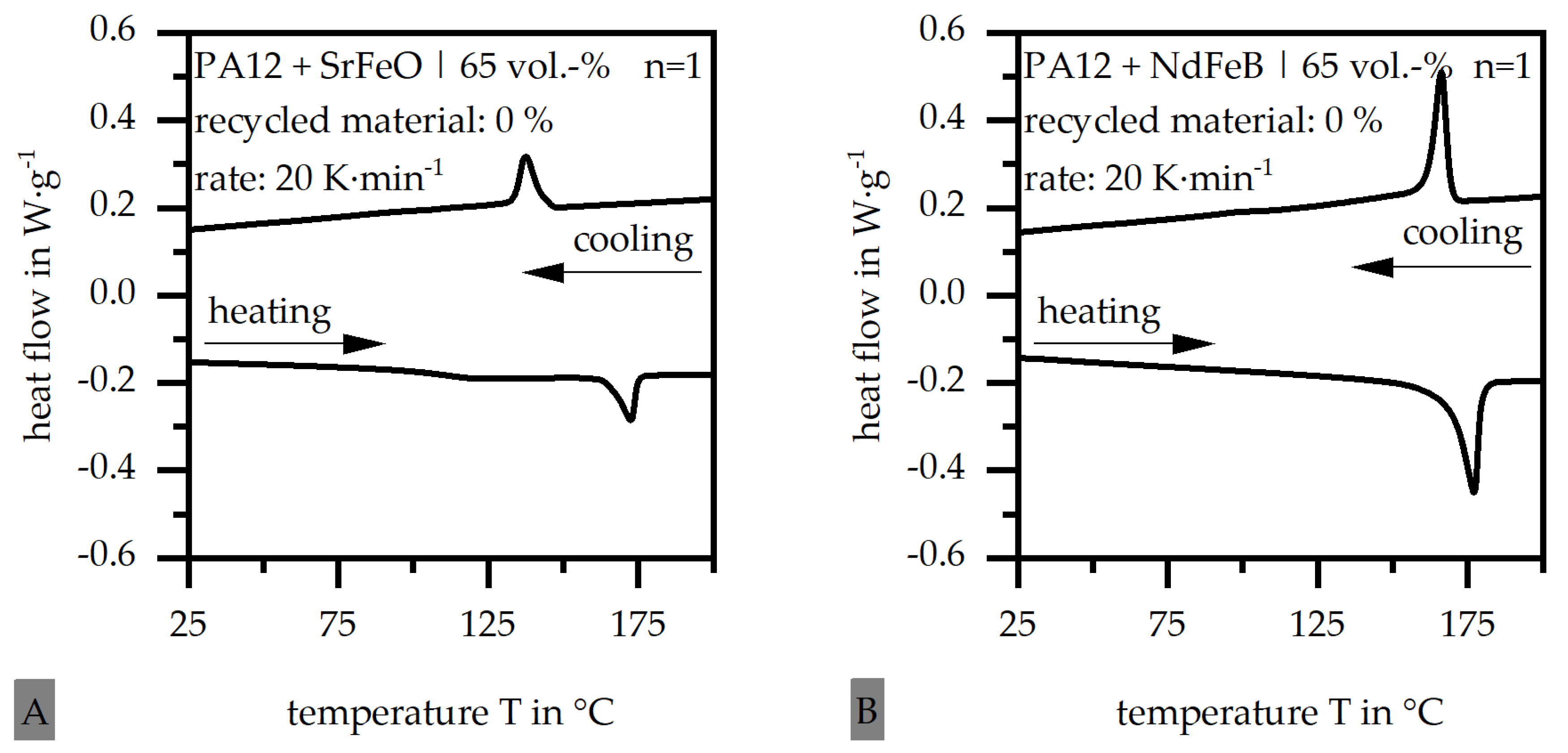
Figure 2.
Position of the gate and the weld line relative to the different gating systems and the 12 pole circular test specimen.
Figure 2.
Position of the gate and the weld line relative to the different gating systems and the 12 pole circular test specimen.

Figure 3.
Schematic route of the creep compliance J relative to the time.
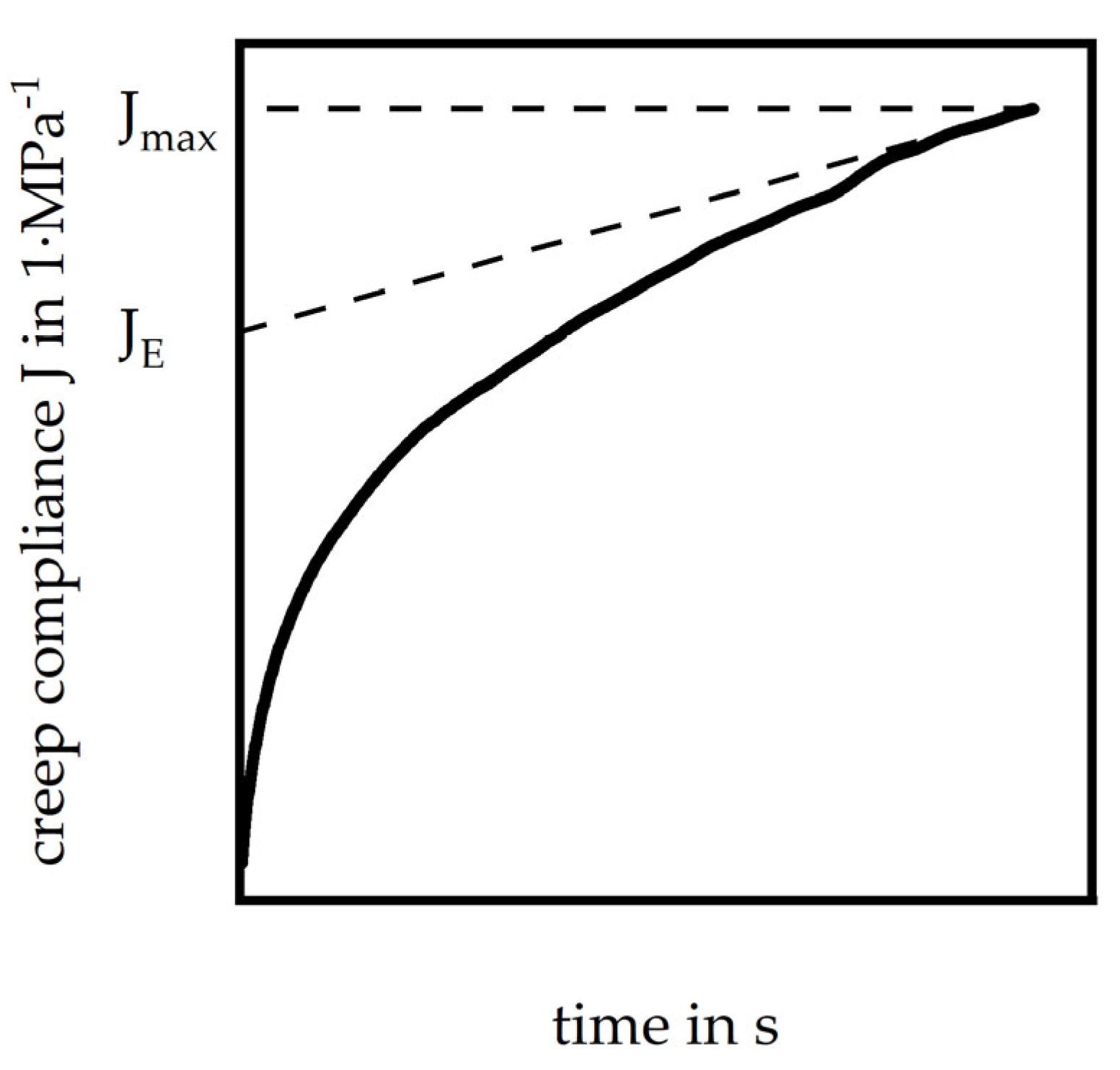
Figure 4.
Schematic setup of the test rig for determining the magnetic flux density on the ring (according to [23]).
Figure 4.
Schematic setup of the test rig for determining the magnetic flux density on the ring (according to [23]).

Figure 5.
Overview of the characteristic poles relative to different gating systems and the 12 pole circular test specimen.
Figure 5.
Overview of the characteristic poles relative to different gating systems and the 12 pole circular test specimen.
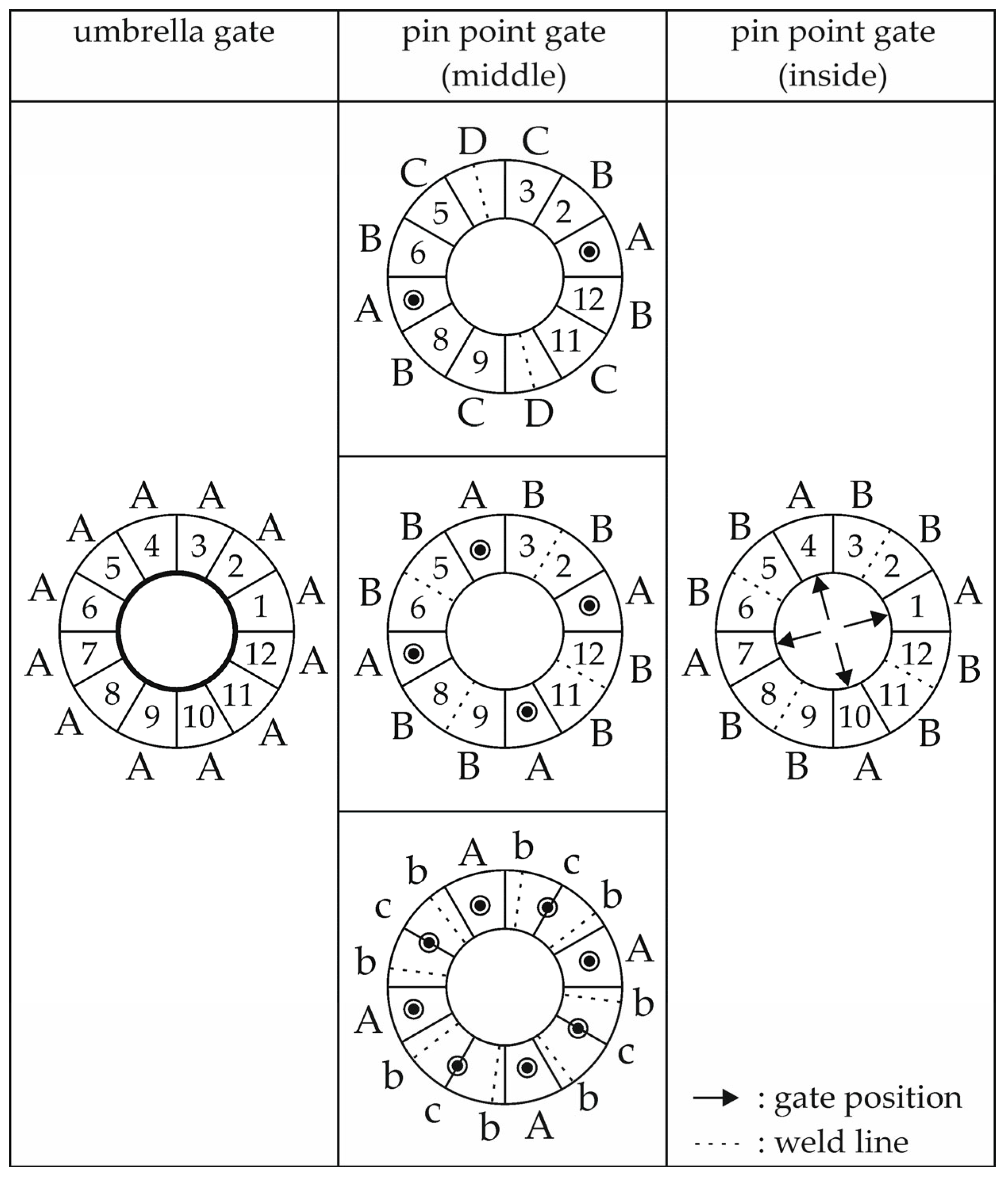
Figure 6.
Sample preparation steps and expected orientation relative to the different regions evaluated.
Figure 6.
Sample preparation steps and expected orientation relative to the different regions evaluated.

Figure 7.
Route of the DSC measurement ((A) second heating|(B) cooling) relative to the amount of recycled material in terms of the hard magnetic filler SrFeO (matrix: PA12|filler grade: 65 vol.-%).
Figure 7.
Route of the DSC measurement ((A) second heating|(B) cooling) relative to the amount of recycled material in terms of the hard magnetic filler SrFeO (matrix: PA12|filler grade: 65 vol.-%).

Figure 8.
Route of the DSC measurement ((A) second heating|(B) cooling) relative to the amount of recycled material in terms of the hard magnetic filler NdFeB (matrix: PA12|filler grade: 65 vol.-%).
Figure 8.
Route of the DSC measurement ((A) second heating|(B) cooling) relative to the amount of recycled material in terms of the hard magnetic filler NdFeB (matrix: PA12|filler grade: 65 vol.-%).

Figure 9.
Route of the TGA measurement ((A) dynamic|(B) isothermal) relative to the amount of recycled material in terms of the hard magnetic filler NdFeB (matrix: PA12|filler grade: 65 vol.-%).
Figure 9.
Route of the TGA measurement ((A) dynamic|(B) isothermal) relative to the amount of recycled material in terms of the hard magnetic filler NdFeB (matrix: PA12|filler grade: 65 vol.-%).
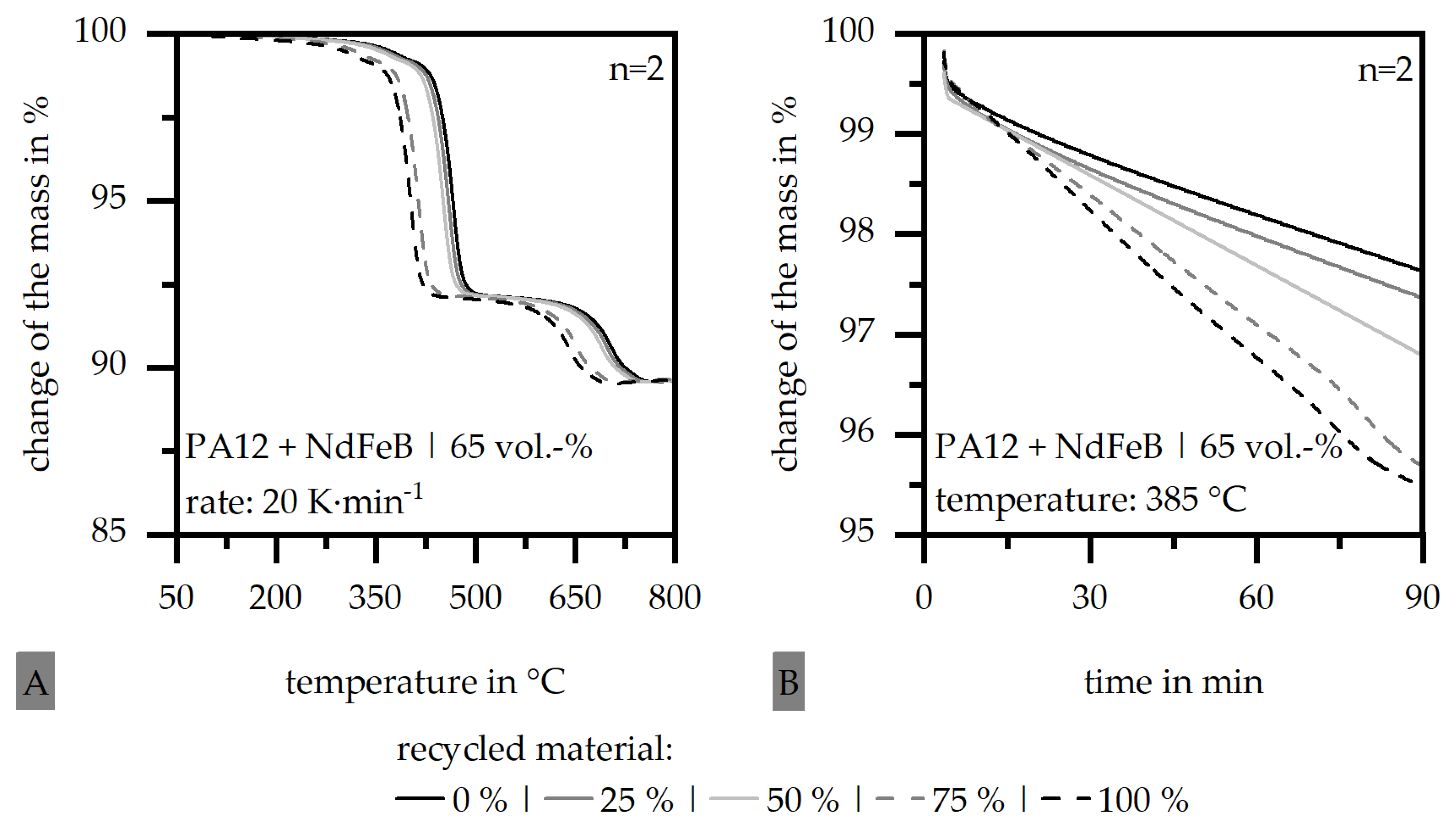
Figure 10.
Particle size distribution of 0% and 100% recycled material based in NdFeB as filler in volumetric (A) and numerical (B) deposition as well as particle images exemplarily (C).
Figure 10.
Particle size distribution of 0% and 100% recycled material based in NdFeB as filler in volumetric (A) and numerical (B) deposition as well as particle images exemplarily (C).
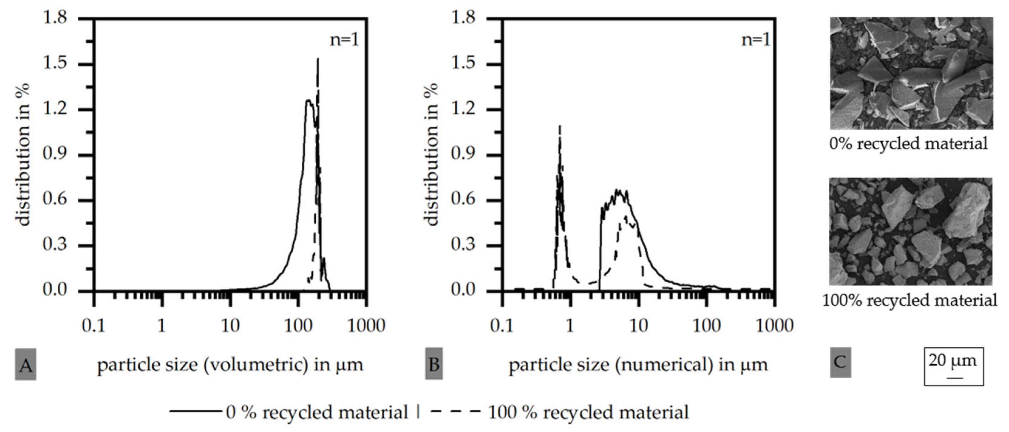
Figure 11.
Change in the complex viscosity η relative to the amount of recycled material in the material system for the hard magnetic filler SrFeO (A) and NdFeB (B) (matrix: PA12|filler grade: 65 vol.-%).
Figure 11.
Change in the complex viscosity η relative to the amount of recycled material in the material system for the hard magnetic filler SrFeO (A) and NdFeB (B) (matrix: PA12|filler grade: 65 vol.-%).
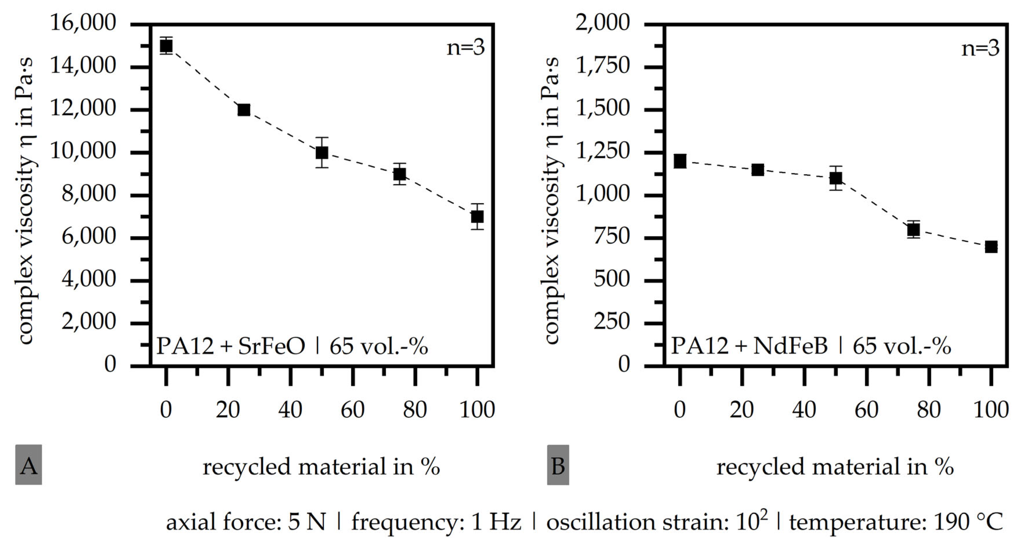
Figure 12.
Route of the creep compliance J (A) and relative amount of the normalized irrecoverable flow (B) relative to the amount of recycled material exemplarily for the hard magnetic filler NdFeB (matrix: PA12|filler grade: 65 vol.-%).
Figure 12.
Route of the creep compliance J (A) and relative amount of the normalized irrecoverable flow (B) relative to the amount of recycled material exemplarily for the hard magnetic filler NdFeB (matrix: PA12|filler grade: 65 vol.-%).

Figure 13.
Magnetic flux density relative to the characteristic poles of the different gating systems ((A) 2-pin-point gate (middle)|(B) 4-pin-point gate (middle)|(C) 8-pin-point gate (middle)|(D) umbrella gate|(E) 4-pin-point gate (inside)) and the amount of recycled material in terms of the hard magnetic filler SrFeO (matrix: PA12|filler grade: 65 vol.-%).
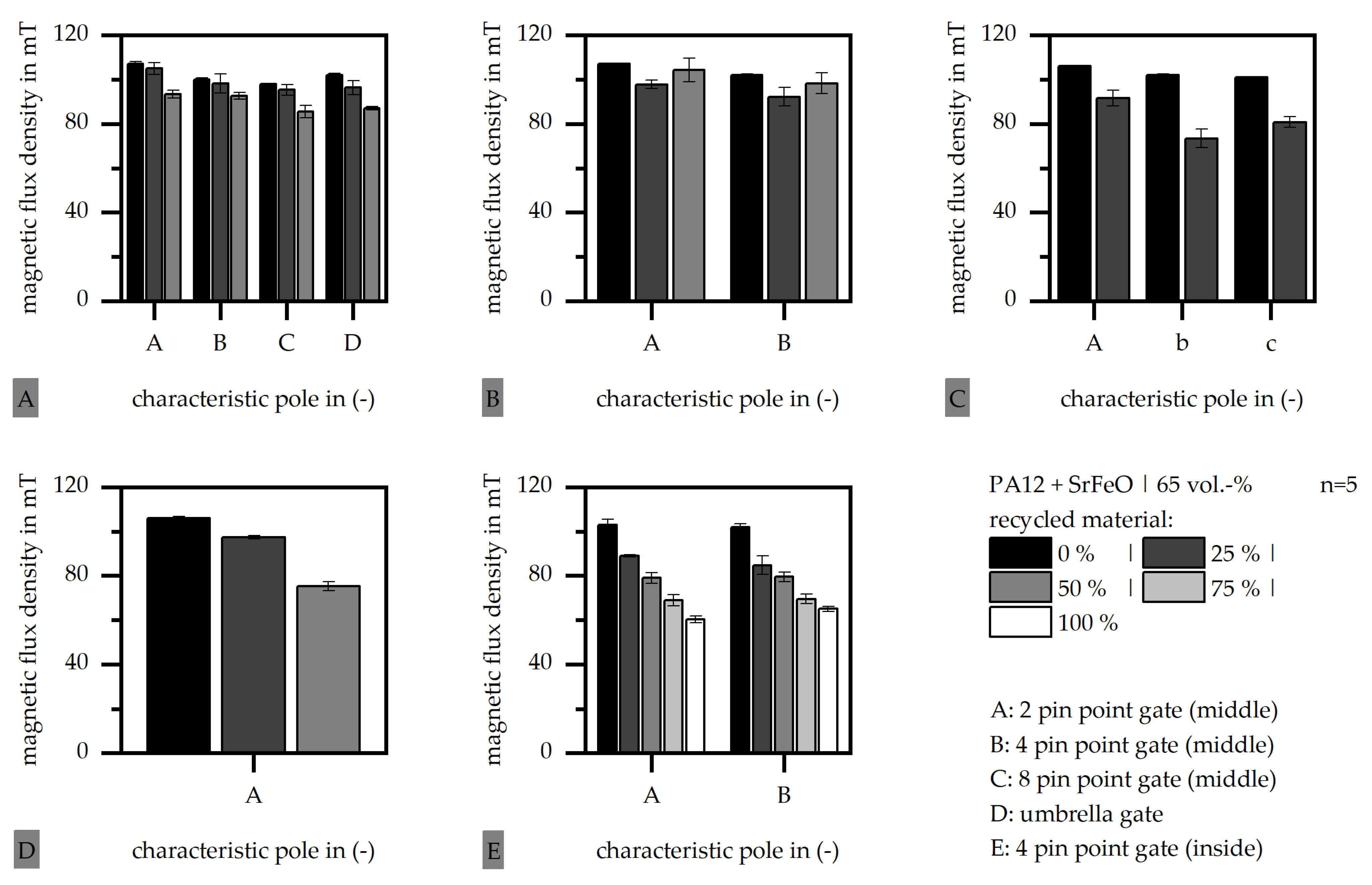
Figure 14.
Deviation of the magnetic flux density relative to 0% recycled material for the characteristic poles of the different gating systems and in terms of the amount of recycled material in terms of the hard magnetic filler SrFeO (A) and NdFeB (B) (matrix: PA12|filler grade: 65 vol.-%).
Figure 14.
Deviation of the magnetic flux density relative to 0% recycled material for the characteristic poles of the different gating systems and in terms of the amount of recycled material in terms of the hard magnetic filler SrFeO (A) and NdFeB (B) (matrix: PA12|filler grade: 65 vol.-%).

Figure 15.
Pole accuracy relative to the characteristic poles of the different gating systems ((A) 2-pin-point gate (middle)|(B) 4-pin-point gate (middle)|(C) 8-pin-point gate (middle)|(D) umbrella gate|(E) 4-pin-point gate (inside)) and the amount of recycled material in terms of the hard magnetic filler SrFeO (matrix: PA12|filler grade: 65 vol.-%).
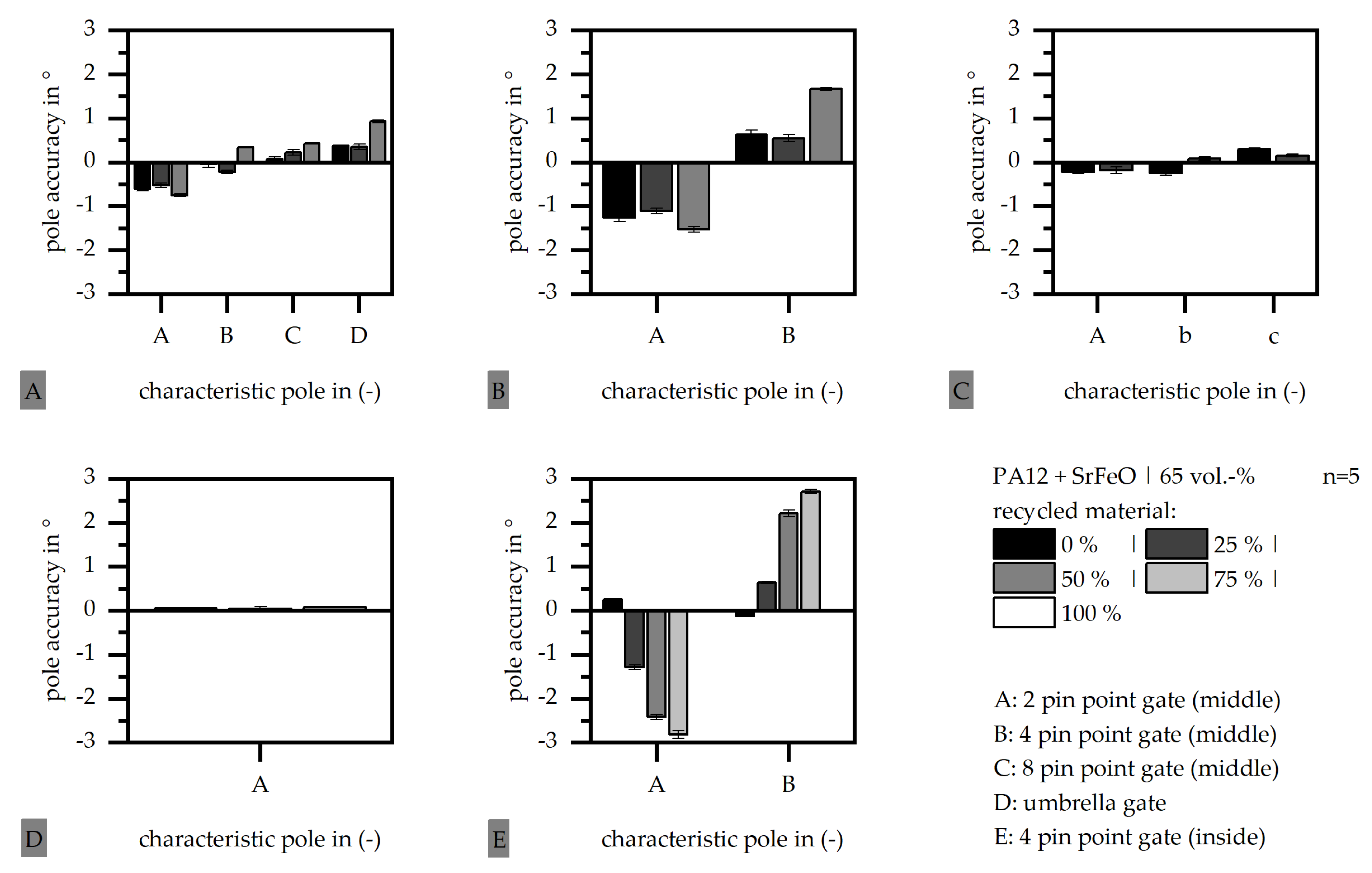
Figure 16.
Orientation of the hard magnetic fillers (exemplarily) relative to positions i to iii on the outside diameter (A) and to positions i to iv (B) for 4-pin-point gate (middle) in terms of the hard magnetic filler SrFeO (matrix: PA12|filler grade: 65 vol.-%) with 50% recycled material.
Figure 16.
Orientation of the hard magnetic fillers (exemplarily) relative to positions i to iii on the outside diameter (A) and to positions i to iv (B) for 4-pin-point gate (middle) in terms of the hard magnetic filler SrFeO (matrix: PA12|filler grade: 65 vol.-%) with 50% recycled material.
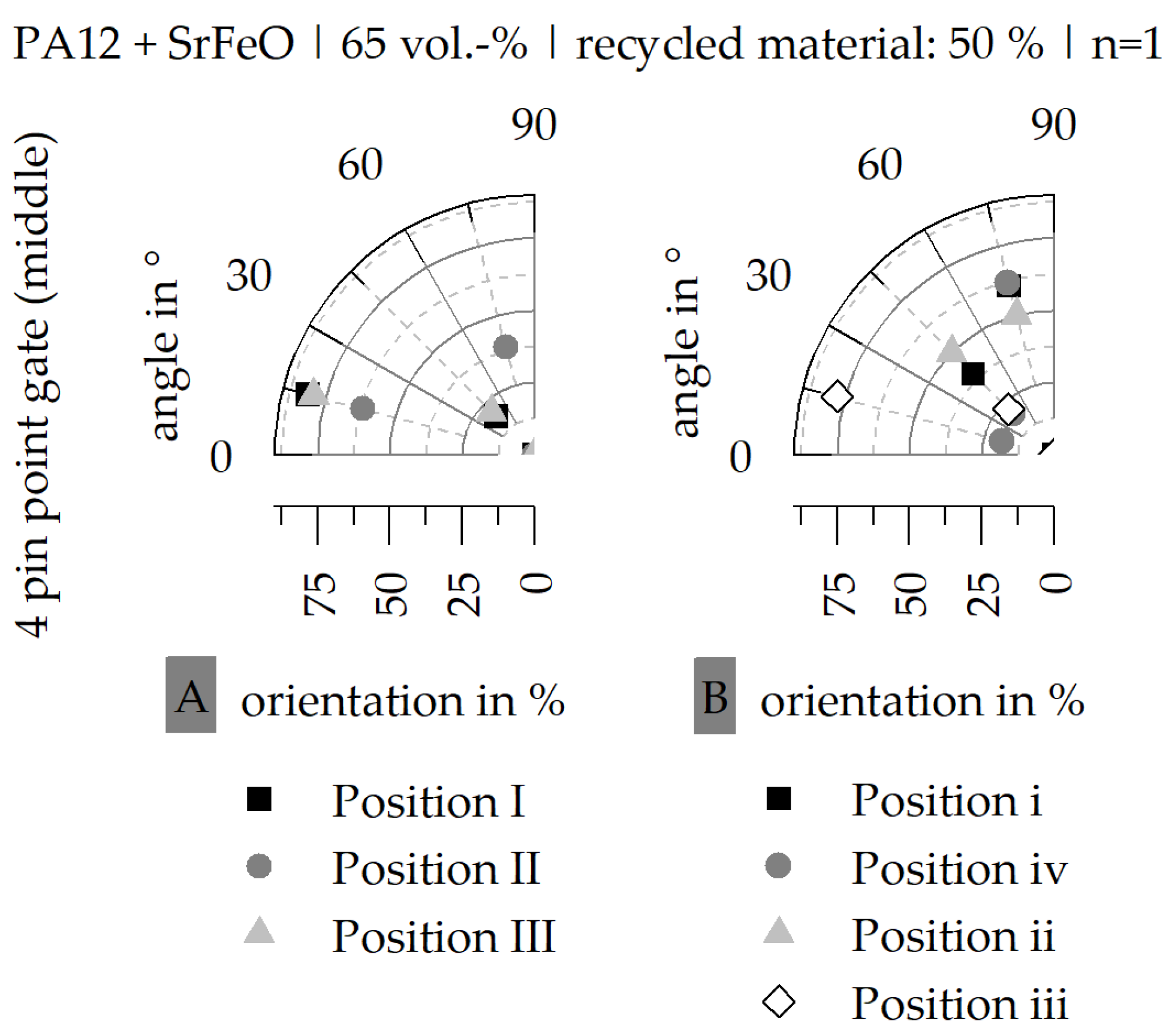
Figure 17.
Orientation of the hard magnetic fillers relative to the different gating systems ((A–C) 2-pin-point gate (middle)|(D–F) 4-pin-point gate (middle)|(G–I) umbrella gate|(J–L) 4-pin-point gate (inside)) in terms of the hard magnetic filler SrFeO (matrix: PA12|filler grade: 65 vol.-%) with 50% recycled material.

Figure 18.
Orientation of the hard magnetic fillers relative to amount of recycled material ((A–C) 0% recycled material|(D–F) 25% recycled material|(G–I) 50% recycled material|(J–L) 75% recycled material) in terms of the hard magnetic filler SrFeO (matrix: PA12|filler grade: 65 vol.-%) with a 4-pin-point gate (inside).


Table 1.
Specification of commercial material systems (unrecycled stadium) including the density ρ and the remanence BR (manufacturer specifications) as well as the amount of recycled material.
Table 1.
Specification of commercial material systems (unrecycled stadium) including the density ρ and the remanence BR (manufacturer specifications) as well as the amount of recycled material.
| Commercial Material | Type | Recycled Material in % | Density in g∙cm−3 | Remanence BR in mT |
|---|---|---|---|---|
| PA12 with SrFeO | HM-1222H | 0|25|50|75|100 | 3.85 | 313 |
| PA12 with NdFeB | RNI-25LF2 | 0|25|50|75|100 | 4.01 | 338 |
Table 2.
Processing parameters of injection molding to fabricate test samples (PA12 with 65 vol.-% SrFeO or NdFeB).
Table 2.
Processing parameters of injection molding to fabricate test samples (PA12 with 65 vol.-% SrFeO or NdFeB).
| Mass temperature | 280 °C |
| Mold temperature | 80 °C |
| Injection speed | 80 mm/s |
| Changeover point | 1000–2400 bar |
| Holding pressure | 500 bar |
Table 3.
Possibilities of fabrication test samples relative to the gating system and amount of recycled material (matrix: PA12|hard magnetic filler: SrFeO and NdFeB|filler grade: 65 vol.-%) (gray highlight: combinations are not possible to be fabricated).
Table 3.
Possibilities of fabrication test samples relative to the gating system and amount of recycled material (matrix: PA12|hard magnetic filler: SrFeO and NdFeB|filler grade: 65 vol.-%) (gray highlight: combinations are not possible to be fabricated).
| Gating System | 2 Pin Point (Middle) | 4 Pin Point (Middle) | 8 Pin Point (Middle) | Umbrella | 4 Pin Point (Inside) |
|---|---|---|---|---|---|
| Amount of Recycled Material in % | - | - | - | - | - |
| 0 | yes | yes | yes | yes | yes |
| 25 | yes | yes | yes | yes | yes |
| 50 | yes | yes | no | yes | yes |
| 75 | no | no | no | no | yes |
| 100 | no | no | no | no | yes |
Table 4.
Possibilities of fabrication test samples relative to the gating system and amount of recycled material with 10% (A) and 20% (B) reduction in the magnetic properties relative to 0% recycled material (matrix: PA12|hard magnetic filler: SrFeO|filler grade: 65 vol.-%) (gray highlight: combinations are not possible to be fabricated).
| Gating System | 2 Pin Point (Middle) | 4 Pin Point (Middle) | 8 Pin Point (Middle) | Umbrella | 4 Pin Point (Inside) |
|---|---|---|---|---|---|
| Amount of Recycled Material in % | - | - | - | - | - |
| A|B | A|B | A|B | A|B | A|B | |
| 25 | yes|yes | yes|yes | no|no | yes|yes | no|yes |
| 50 | no|yes | no|yes | - | no|no | no|no |
| 75 | - | - | - | - | no|no |
| 100 | - | - | - | - | no|no |
Table 5.
Possibilities of fabrication test samples relative to the gating system and amount of recycled material with 10% (A) and 20% (B) reduction in the magnetic properties relative to 0% recycled material (matrix: PA12|hard magnetic filler: NdFeB|filler grade: 65 vol.-%) (gray highlight: combinations are not possible to be fabricated).
| Gating System | 2 Pin Point (Middle) | 4 Pin Point (Middle) | 8 Pin Point (Middle) | Umbrella | 4 Pin Point (Inside) |
|---|---|---|---|---|---|
| Amount of Recycled Material in % | - | - | - | - | - |
| A|B | A|B | A|B | A|B | A|B | |
| 25 | yes|yes | no|yes | no|no | no|no | no|yes |
| 50 | no|no | no|yes | - | no|no | no|no |
| 75 | - | - | - | - | no|no |
| 100 | - | - | - | - | no|no |
Table 6.
Possibilities of fabrication test samples relative to the gating system and amount of recycled material with 10% (A) and 20% (B) reduction in the magnetic properties relative to 0% recycled material and with respect to a maximum of 1° pole accuracy (matrix: PA12|hard magnetic filler: SrFeO|filler grade: 65 vol.-%) (gray highlight: combinations are not possible to be fabricated).
| Gating System | 2 Pin Point (Middle) | 4 Pin Point (Middle) | 8 Pin Point (Middle) | Umbrella | 4 Pin Point (Inside) |
|---|---|---|---|---|---|
| Amount of Recycled Material in % | - | - | - | - | - |
| A|B | A|B | A|B | A|B | A|B | |
| 25 | yes|yes | yes|yes | no|no | yes|yes | no|no |
| 50 | no|yes | no|no | - | no|no | no|no |
| 75 | - | - | - | - | no|no |
| 100 | - | - | - | - | no|no |
Table 7.
Possibilities of fabrication test samples relative to the gating system and amount of recycled material with 10% (A) and 20% (B) reduction in the magnetic properties relative to 0% recycled material and with respect to a maximum of 1° pole accuracy (matrix: PA12|hard magnetic filler: NdFeB|filler grade: 65 vol.-%) (gray highlight: combinations that cannot be fabricated).
| Gating System | 2 Pin Point (Middle) | 4 Pin Point (Middle) | 8 Pin Point (Middle) | Umbrella | 4 Pin Point (Inside) |
|---|---|---|---|---|---|
| Amount of Recycled Material in % | - | - | - | - | - |
| A|B | A|B | A|B | A|B | A|B | |
| 25 | yes|yes | no|yes | no|no | no|no | no|no |
| 50 | no|no | no|no | - | no|no | no|no |
| 75 | - | - | - | - | no|no |
| 100 | - | - | - | - | no|no |
Disclaimer/Publisher’s Note: The statements, opinions and data contained in all publications are solely those of the individual author(s) and contributor(s) and not of MDPI and/or the editor(s). MDPI and/or the editor(s) disclaim responsibility for any injury to people or property resulting from any ideas, methods, instructions or products referred to in the content. |
© 2024 by the authors. Licensee MDPI, Basel, Switzerland. This article is an open access article distributed under the terms and conditions of the Creative Commons Attribution (CC BY) license (https://creativecommons.org/licenses/by/4.0/).
Share and Cite
MDPI and ACS Style
Rösel, U.; Drummer, D. Changes in Material Behavior according to the Amount of Recycled Magnetic Materials in Polymer-Bonded Magnets Based on Thermoplastics. Magnetism 2024, 4, 1-23. https://doi.org/10.3390/magnetism4010001
AMA Style
Rösel U, Drummer D. Changes in Material Behavior according to the Amount of Recycled Magnetic Materials in Polymer-Bonded Magnets Based on Thermoplastics. Magnetism. 2024; 4(1):1-23. https://doi.org/10.3390/magnetism4010001
Chicago/Turabian StyleRösel, Uta, and Dietmar Drummer. 2024. "Changes in Material Behavior according to the Amount of Recycled Magnetic Materials in Polymer-Bonded Magnets Based on Thermoplastics" Magnetism 4, no. 1: 1-23. https://doi.org/10.3390/magnetism4010001