1. Introduction
Isolated magnetic skyrmions are particle-like topological solitons with complex non-coplanar spin structure [
1,
2,
3,
4] stabilized in noncentrosymmetric magnetic materials by specific Dzyaloshinskii–Moriya interactions (DMI) [
5]. Phenomenologically, DMIs are expressed as the first derivatives of the magnetization
with respect to the spatial coordinates, the so called Lifshitz invariants (LI):
The skyrmion “knots” are robust against small perturbations and cannot be continuously unwound, i.e., DMI provides a viable stabilization mechanism, protecting skyrmions from radial instability [
1,
2] and overcoming the constraints of the Hobart–Derrick theorem [
6].
The skyrmion field configurations are elements of second homotopy group and can be characterized by a topological charge or skyrmion number [
7]:
describing how many times the magnetization field
within the single skyrmion wraps around the sphere
.
Chiral interactions having the same functional form as (
1) may appear also in many other systems: in ferroelectrics with a non-centrosymmetric parent paraelectric phase, non-centrosymmetric superconductors, multiferroics [
8,
9,
10], or even in metallic supercooled liquids and glasses [
11]. Localized states in these systems are also named skyrmions by analogy with the Skyrme model for mesons and baryons [
12]. Chiral liquid crystals (CLC) are considered as ideal model systems for probing the behavior of different modulated structures on the mesoscopic scale [
13].
The current focus of skyrmionics revolves around axisymmetric skyrmions within the saturated ferromagnetic state of non-centrosymmetric magnets [
2]. The magnetization twist is localized in two spatial directions (2D) and the axes of skyrmions are co-aligned with an applied magnetic field (in the present manuscript, the field is applied along
x), i.e., the magnetization in the center is opposite to the field and gradually rotates to the field-aligned state at the outskirt. Homogeneous extension of such magnetic textures into the third direction along the field forms skyrmionic filaments or strings. Recently, hexagonal skyrmion lattices (SkL) and isolated skyrmions (IS) of such a “standard” skyrmion variety were discovered in bulk chiral magnets near the Curie temperature [
14,
15,
16] and in nanolayered geometries over larger temperature intervals [
17,
18,
19,
20]. The internal structure of such
axisymmetric skyrmions, which is generally characterized by the repulsive inter-skyrmion potential, has been systematically investigated theoretically [
1,
2] and experimentally by spin-polarized scanning tunneling microscopy in PdFe bilayers with induced Dzyaloshinskii–Moriya interactions and strong easy-axis anisotropy [
4,
21]. It was found that the existence region of axisymmetric ISs is restricted by strip-out instabilities at low fields and a collapse at high fields. Due to the nanometer size of skyrmions, their topological stability, and possibility to manipulate by electric currents, the magnetic skyrmions are considered promising objects for the next-generation memory and logic devices [
22,
23,
24].
In Ref. [
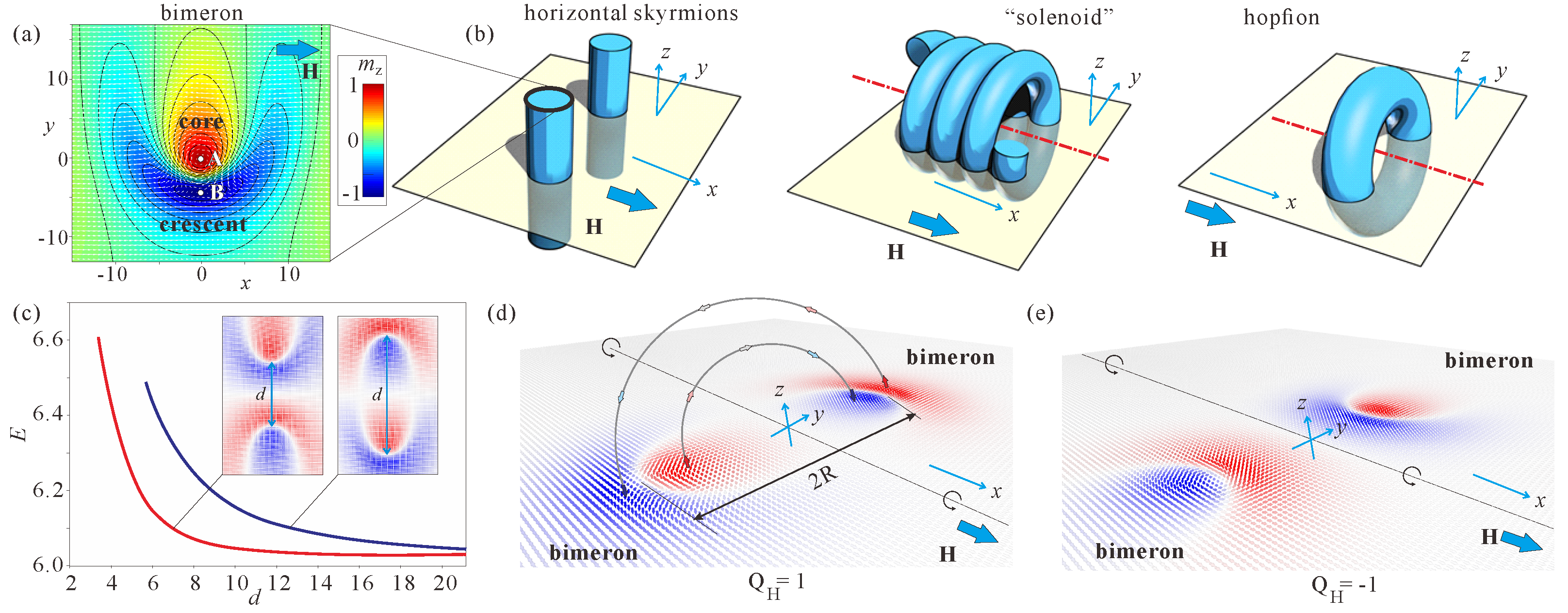
25], however, it was contended that the saturated state may permit yet another type of isolated skyrmions with their axes oriented perpendicular to the field. Such 2D skyrmions are compelled to develop a
non-axisymmetric shape in order to blend into the spin pattern of the homogeneous state and to preserve their total topological charge
computed in the plane
(
Figure 1a,c). Alternatively, the skyrmion cross-section can be thought of as a pair of merons with the topological charges
. For example, starting from the upper side of the depicted bimeron in the plane
(
Figure 1a), the magnetization makes the full swing from 0 to
: it passes through the points
A and
B with the magnetization parallel to the
z axis,
and
, which can be considered as centers of a circular skyrmion core and an anti-skyrmion crescent, respectively. Unlike the repulsive axisymmetric ISs, such non-axisymmetric skyrmions develop anisotropic skyrmion–skyrmion interaction [
25,
26]. Depending on the relative orientation of two individual skyrmions, this potential can be attractive, leading to the formation of biskyrmion or multiskyrmion chains, aligned along the axis connecting points
A and
B, as well as repulsive in the perpendicular direction (i.e., along
y) [
25].
Figure 1c exhibits the repulsive potential of two bimerons with opposite topological charges oriented inward either with their crescents (red curve) or with their cores (blue curve). Since the distorted crescent part is less spacious, the interaction potential in the first case shows pronounced repulsion at much smaller distances between bimerons (red curve). The distance
d is measured at the magnetization value
opposite to the field.
Interestingly, propagation of such skyrmion filaments into the third direction may give rise to a number of exotic spin textures (
Figure 1b). First of all, such skyrmions may run perpendicular to the field (along the
z axis in the present case, first panel in
Figure 1b). Such filaments were dubbed horizontal skyrmions in Ref. [
27]. It was shown that isolated horizontal skyrmions may attract/couple with ordinary skyrmions oriented along the field and thus form clusters with mutually orthogonal orientations of constituent skyrmions. In Ref. [
28], the horizontal skyrmions were shown to swirl into “solenoids”/“springs” with their axes parallel to the field (second panel in
Figure 1b). Such spin “solenoids” may exist in two varieties depending on which part of a curled 2D bimeron faces the interior. Subsequently, the solenoids may squeeze into ordinary skyrmions with both polarities (and therefore, opposite topological charges): within the homogeneous state, however, only the ISs with the negative polarity maintain although within the conical phase—both skyrmion varieties are feasible [
28]. The attraction between two skyrmion varieties may also lead to a family of so-called target-skyrmions [
28]: in this sense, the topological charge of the horizontal skyrmion may either add or subtract from the topological charge of the skyrmion along the field, i.e., “massive” targets with the multiple charges
Q can also be created.
In the present manuscript, we consider the swirling of horizontal skyrmions into the doughnut-shaped hopfions, i.e., we just wind the 2D bimeron texture around the
x axis (the field direction) until it forms a localized object. We show that two types of hopfions obtained by such a procedure (and thus having opposite Hopf indices (
4)) have quite distinct spin textures and internal properties. Most importantly, we pose the question of whether hopfions represent metastable states (local energy minima) in bulk chiral helimagnets, inevitably contract and transform into torons, or collapse altogether. We argue that competing cubic and exchange anisotropies constitute a valid mechanism behind hopfion metastability in chiral magnets. This would pave the way for possible applications of hopfions in spintronic devices.
2. Phenomenological Model
The standard model for magnetic states in bulk cubic non-centrosymmetric ferromagnets is based on the energy density functional [
5,
29]
including the principal interactions essential to stabilize modulated states: the exchange stiffness with constant
A, Dzyaloshinskii–Moriya coupling energy with constant
D, and the Zeeman energy;
is the unity vector along the magnetization vector
, and
is the magnetic field applied exclusively along
x-axis. The polar angle
of the magnetization is measured from the
x axis, the azimuthal angle
—from the
y axis.
For the forthcoming calculations, we use non-dimensional variables. The lengths are expressed in units of
, i.e., the length scales are related to the period of the spiral state in zero field
, and reflect the fact that the ground state of the system in the form of a single-harmonic mode is yielded as a result of the competition between the counter-acting exchange and DM interactions in Equation (
3). Thus,
introduces a fundamental length characterizing the magnitude of chiral modulations in non-centrosymmetric magnets.
, where
, is the reduced magnitude of the applied magnetic field. Within the isotropic model (
3), a conical single-harmonic spiral with the wave vector along the field represents the global energy minimum. The critical field value
marks the saturation of the conical phase into the ferromagnetic state. Since we aim at hopfions surrounded by the homogeneous state, the field value is taken,
.
As a main numerical tool to minimize the functional (
3), we use the MuMax3 software package (version 3.10), which calculates magnetization dynamics by solving the Landau–Lifshitz equation using the finite-difference discretization technique (see for details Ref. [
30]). The grid size is
and the cell size is equal along all coordinate axes,
. As an initial “seed” for numerical procedures, we use 2D bimeron pairs (as those depicted in
Figure 1d,e) with opposite topological charges/polarities. We prepared a set of such pairs with different distances
d between them: first, we use default initial states in the form of ordinary skyrmions with their axes along
z; then, by applying the field along
x, we obtain bimeron configurations (this is the reason why we have chosen the
x direction for the magnetic field also for three-dimensional (3D) spin textures). To prepare a 3D hopfion, we align the magnetization along circular trajectories connecting the characteristic magnetization points in the plane
; for example,
, which correspond to the centers of bimeron cores and crescents; additionally, we pin the magnetization
along the circle with the radius
R, which later will be referred to as a hopfion radius (
Figure 1d). After the relaxation procedure, we obtain hopfions of two varieties with variable radii
R. As compared with the methods based on the Ansatz solutions for hopfions [
31], the present approach has a number of advantages: (i) a trajectory along which one replicates bimerons can be entangled and encompass, for example, different knotted structures; thus, the search for multidimensional solitons can be systematized; it is often impossible to write an appropriate Ansatz for such particle-like states; (ii) one can investigate addition and subtraction of hopfions and investigate “nested” spin distributions, i.e., around a hopfion with
one could wind another hopfion with the opposite or the same Hopf index [
31]; (iii) one could obtain a smooth transformation between horizontal and vertical skyrmions and thus speculate about hopfions located in other coordinate planes.
3. Internal Structure of Hopfions
The structure of obtained hopfions is characterized by the Hopf invariant
, which can be calculated from the Whitehead integral expression [
32,
33]:
The components of the emergent magnetic field are given by
and cyclic permutations for
and
[
34].
is the corresponding vector potential,
. To find the components of
, one usually exploits the fact that the vector potential is far from unique, i.e., one can choose a differentiable scalar function
f on
to make zero one of the components of
, e.g.,
[
35]. Then, the other two components can easily be obtained by integrating
. By performing the integration according to (
4), we find that two types of hopfions have Hopf indices of opposite sign,
. In the following, the soliton with
will be called hopfion, whereas its counterpart – anti-hopfion.
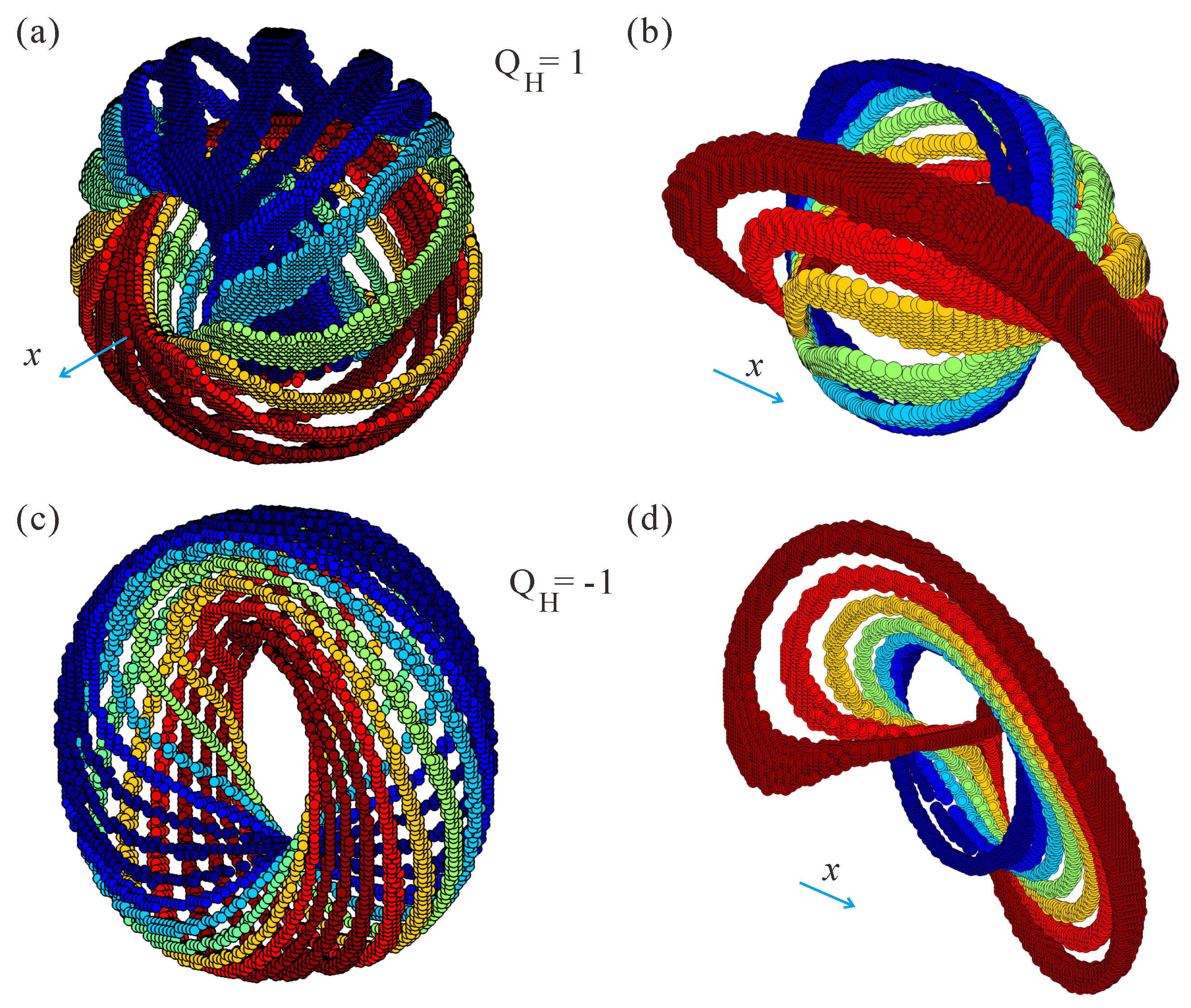
Plots of the preimages of hopfions and anti-hopfions are shown in
Figure 2. Preimage is the spatial region of the ferromagnet’s 3D space with a single
-orientation corresponding to a point on
[
31]. Preimages in
Figure 2a,c correspond to
and varying azimuthal angle
. The color scheme indicates the value of the
component varying from −1 (blue) to 1 (red) with the step
. Preimages in
Figure 2b,d correspond to the varying polar angle
and
; the color reflects the
magnetization component along the field with the same step
. Any pair of preimage curves links
times (in our case, just once), corroborating the interpretation of
as a linking number. Still, the network of preimages is obviously different.
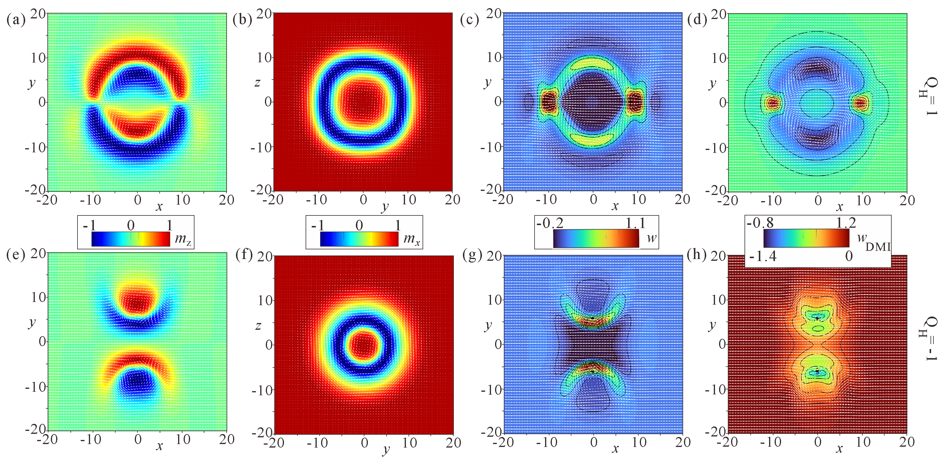
The internal spin patterns of hopfions and anti-hopfions are depicted in
Figure 3 for two cross-sections
(
Figure 3a,e) and
(
Figure 3b,f). Whereas in the former case, hopfions look as pairs of coupled bimerons with opposite polarities and can be differentiated whether the crescent faces exterior or the interior of a hopfion, in the latter case, hopfions represent so-called target skyrmions [
36,
37] (alternatively called skyrmioniums [
38]), in which the magnetization undergoes a rotation by the angle
. Note that the magnetization rotation occurs in accordance with the DMI, which prescribes the relation between the azimuthal angle of the magnetization and the cylindrical coordinate system, i.e.,
.
Distribution of the total energy density (
Figure 3c,g) and the energy density of the DMI (
Figure 3d,h) provide even more insight into distinct properties of hopfions. The hopfions (
Figure 3c,d) exhibit the parts with the unfavorable rotational sense against the DMI (red regions in
Figure 3d). The total energy density in
Figure 3c acquires an “egg”-like pattern with the positive energy density forming a shell. On the contrary, the anti-hopfion exhibits only one sense of rotation as shown by its DMI energy density (
Figure 3h). The positive energy density is also localized to quite narrow parts surrounding the crescents.
4. Metastability of Hopfions in Bulk Helimagnets
Within the isotropic model (
3), the total energy
W of hopfions computed with respect to the homogeneous state,
, represents almost a straight line (dashed black line in
Figure 4a): as a result, both hopfion varieties contract and decrease their radii to reduce the positive eigen-energy. Interestingly, the eigen-energies are degenerate and stay the same up to quite small hopfion sizes for both hopfion types. In this case, constituent bimerons (first and third panels in
Figure 4b) are spatially localized and do not significantly deform their internal structure. During the contraction process, the anti-hopfion transforms into a toron (
Figure 4c), which represents a localized particle consisting of two Bloch points at a finite distance and a convex-shaped skyrmion stretching between them [
39,
40]. In the transversal
cross-section, the magnetization rotates from the state
in the center till the state
at the outskirt as it would be in ordinary 2D skyrmions (second panel in
Figure 4c). The energy density distribution reflects a great energy penalty associated with point defects (third panel in
Figure 4c). The topological transition between the hopfion and the toron states was recently studied in a chiral magnet nanodisk sandwiched by two films with perpendicular magnetic anisotropy [
41].
The (
)-hopfion, however, simply collapses into the homogeneous state, the behavior being consistent with the transformation of “solenoids” considered in Ref. [
28].
To realize hopfions in bulk chiral ferromagnets, therefore, one should find a parameter range/region where static hopfions emerge as local or global minima of the free energy. Here, we notice that alternatively. hopfions can be embedded into a helical or conical background of chiral magnets and are called heliknotons [
42]. We, however, concentrate on the areas of phase diagrams with the homogeneous ferromagnetic background.
To make the search more systematic, we first pose the question, of whether the slope of the energy curve in
Figure 4a can be affected by additional anisotropies, which are inherent in cubic helimagnets. In particular, it is known that the cubic anisotropy
plays a significant role in bulk cubic helimagnets and may even lead to the thermodynamical stability of skyrmions far from the ordering temperatures [
43]. Recently, low-temperature skyrmions have been observed in the Mott insulator Cu
OSeO
, accompanied by tilted spirals. The theoretical explanation of SkL stability by the cubic anisotropy rather hinges on the effect imposed on one-dimensional spiral states than on skyrmions. In fact, the ideal magnetization rotation in the conical state is considerably impaired by the easy and hard anisotropy axes, e.g., for the field along
crystallographic directions. Through this mechanism, skyrmions, which are more resilient to anisotropy-induced deformations, due to their two-dimensional nature, gain stability. For our purpose of searching for metastable hopfions, this effect of cubic anisotropy on the conical state would also become helpful: we would like to decrease the field value (to avoid any possible hopfion collapse as observed for isolated skyrmions [
2]) but still stay within the homogeneous state. In Cu
OSeO
, the easy cubic axes are
(the anisotropy constant
), and the field co-aligned with one of these axes leads to the first-order phase transition between the conical and homogeneous states with the field value
much lower than
in the isotropic case [
43]. The green line in
Figure 4d shows the critical field
in dependence on the cubic anisotropy. In the following simulations, we will look for metastable hopfions exactly along this line. Furthermore, indeed, we find that the slope of the hopfion eigen-energy decreases by the simultaneous effect of the weaker magnetic field and the cubic anisotropy. In particular, (
)-hopfion acquires the smallest slope possible in this case for
(red line in
Figure 4a): to relax such a hopfion with mumax3 no additional pinning is needed, the relaxation procedure reaches some satisfactory accuracy and preserves hopfions; we believe that in the experiments the observation of hopfions for these anisotropy values would also become possible owing to larger relaxation times.
The anti-hopfion exhibits a slightly larger energy slope (dotted blue line in
Figure 4a), but the lower energy at smaller radii. This can be explained by the larger hopfion sizes for the included cubic anisotropy (second and fourth panels in
Figure 4b) and distortions of bimeron cores. The field value
for both curves corresponds to the line
for
.
The blue dashed line
in
Figure 4d signifies the phase transition between the FM state and a helicoid with the wave vector perpendicular to the field. For relatively large anisotropy values (to the right of the intersection point
C), this field value becomes higher than the field of the cone saturation
. Below the line
, hopfions are found to undergo elliptical distortions and elongations along the
x direction as was pointed out for isolated skyrmions: in this sense, ISs/hopfions serve as nuclei of the more energetically favorable helical phase.
Figure 4e shows the variation in the slope of the curves
,
, depending on the cubic anisotropy. At first, the slope drastically decreases following the tendency of the critical field
. Then, it reaches the minimum and starts to grow again, which is consistent with the inflection point of the line
.
As the second important step, to find the metastability region of hopfions, we engage the exchange anisotropy. In Cu
OSeO
, the exchange anisotropy
has easy
axes (i.e.,
) and therefore competes with the cubic anisotropy (
5). Interestingly, neither the conical state nor the helicoid “feel” the exchange anisotropy: energy of the exchange anisotropy is zero for the conical phase, since the magnetization derivatives in (
6) all vanish. Magnetization rotation in hopfions, on the contrary, acquires the negative
energy. At larger
values, an energy minimum corresponding to metastable hopfions appears (
Figure 4f). The mechanism is based on the energy balance between the cubic anisotropy and the exchange interaction, which make hopfions smaller, and the exchange anisotropy trying to inflate hopfions in order to increase the extension of rotational regions. We notice that the relatively large anisotropy values leading to hopfion metastability correspond to low temperatures in the bulk chiral host Cu
OSeO
. In Ref. [
43], the values
were found to reproduce the experimental results. Isolated hopfions, in this case, will be surrounded by the clusters of skyrmions and the domains of the tilted spiral states, which were experimentally shown to coexist in the low-temperature interval [
43]. This fact may impede direct and unambiguous observation of hopfions in this bulk helimagnet.
5. Discussion and Conclusions
Nowadays, 3D hopfions are of great interest due to their potential application in three-dimensional spintronic devices, the reason for this being the emergent electromagnetic response and non-trivial dynamic properties under external stimuli. Hopfions have recently been observed in magnetic [
44], ferroelectric [
45] and liquid crystals [
31,
39], and have been studied in Bose–Einstein condensates [
46]. Usually, one has to “create” some “special” conditions to observe hopfions: (i) in chiral liquid crystals, the difference in elastic constants alongside with the surface anchoring facilitate hopfion stability; (ii) in different nanostructures [
41] or multilayers [
44], one modifies the perpendicular magnetic anisotropy to create some energy barrier and prevent hopfion collapse; (iii) in frustrated systems [
47,
48] with the competing exchange interactions, both senses of the magnetization rotation are energetically equivalent and thus promote hopfions. Anyway, in these material systems, one may create even more complicated hopfions with the bimeron pattern rotating along the circular trajectory. In this case, the
cross-section would exhibit target-skyrmions with the anti-skyrmion fashion of rotation but no additional energy “penalty” due to the Lifshitz invariants. In the cross-sections
and
, different bimeron parts will face the hopfion interior.
In the present manuscript, we, however, use the standard Dzyaloshinskii model for bulk cubic helimagnets. The hopfion texture can be conventionally characterized by the linked set of preimages: the preimages corresponding to any point on a sphere densely fill the surface of an associated withrus The calculated Hopf invariant equals 1 for hopfions and −1 for anti-hopfions. We, however, give another perspective on the internal structure of hopfions. Hopfions are considered a result of the swirling of 2D bimerons formed perpendicular to the applied magnetic field. Such a method allows us to obtain not only the aforementioned -hopfions, but also speculate about more exotic spin textures as “solenoids” and/or horizontal skyrmions. In particular, the smooth connection of solenoids (which are essentially ordinary skyrmion filaments oriented along the field) and the horizontal skyrmions can easily be imagined and, thus, one may attempt to construct versatile 3D solitons. Moreover, the internal properties of hopfions can be analyzed starting from the 2D bimeron patterns or 2D target-skyrmions, i.e., the stability of 2D solitons is vital for the stability of 3D hopfions as well. In particular, we avoid spin patterns obtained in a 2D hopfion cross-section, which do not comply with the Lifshitz invariants for cubic helimagnets.
To find metastable hopfions surrounded by the homogeneous state, we supplement the model by the cubic and exchange anisotropies, which are innate in B20 systems such as Cu
OSeO
. The experiments invoked to indicate the hopfion presence in this bulk helimagnet should, however, take into account skyrmion clusters and tilted spiral states, which coexist with the homogeneous state in the suggested parameter range. At the same time, the inhomogeneous magnetic environment may induce hopfion nucleation. A similar strategy on hopfion observation was recently pursued in a cubic helimagnet FeGe [
49], in which the cubic anisotropy and the temperature-induced change in easy axes contribute to the hopfion metastability. The fractional hopfions and their ensembles have been created by flipping the external field or flowing a pulsed current.
At the same time, we admit that the influence of small anisotropic energy terms (cubic and exchange anisotropies) on the hopfion structures and the related question of hopfion stability are far from being completely answered in the present paper. Indeed, depending on the control parameters, one may encounter many degenerate homogeneous states stabilized by the cubic anisotropy as well as a multitude of local energy minima with states oblique with respect to the field (see for details Ref. [
50]). Thus, by varying the direction of the applied magnetic field with respect to the easy anisotropic axes, one may “strengthen” some parts of a hopfion (will be performed elsewhere).


