1. Introduction
Electromagnetic systems and applications are well-known systems in all scientific, industrial, and medical sectors where electromagnetic excitations are in use and necessary for acting and sensing. The concept of electromagnetic excitation is typically based on the physical principle of applying a dedicated DC or AC current to copper-based coils to generate a magnetic field strength. To apply the calculated magnetic force, it is usually necessary to increase the magnetic flux density. This will be realized by using ferromagnetic metals/steels and their alloys. The electromagnetic characteristics of these materials are primarily determined from their electrical conductivity and magnetic permeability. Depending on the realization concept, the three basic magnetic forces and their combinations are sources delivering the acting event, the Lorentz force, the reluctance force, and the force applied by permanent magnets.
Simple magnetic circuits and geometries can be analyzed using analytical techniques to compute the magnetic force, but when dealing with complex structures, these methods may not be adequate. Thus, in order to obtain precise solutions, it is essential to use numerical techniques that involve discretizing the geometry. One such widely used method is the finite element method (FEM) with standard workflow steps. In an initial step, the complete system must be analyzed according to their symmetrical properties, e.g., cylinder symmetrical, to choose the coordinate system setup 2D, xy, rφ, or 3D, xyz, r,φ,z. This workflow optimizes the simulation/calculation time. The next step built up the CAD elements of the complete system. Every element will be characterized by the geometrical dimension and by the specification of the electromagnetic property’s electrical conductivity and magnetic permeability. Finally, the system excitation will be defined by applying a dedicated current density on the excited element, e.g., the copper coil. The FEM work on the principle to realize a discretization of the complete space or area. Time dependency or time independent static conditions leads to different solvers and different handling of the FEM-calculated system matrix which will be solved. Without sufficient knowledge about the electrical conductivity and the magnetic permeability of all system elements the solutions deviates from the evaluated real electromagnetically system. Therefore, the magnetic system property permeability is one important input part which must be investigated before it is used in FEM. The aim of this paper is to first evaluate magnetic materials used in electromagnetic systems, the possible measure principles, and typical “islands values” of the magnetic permeability. Based on this, additional research will be proposed: how to evaluate the permeability by a mixed, an experimentally, and a simulated setup.
The general measuring of the magnetic material properties is described in the IEC (International Electrotechnical Commission) norms. The IEC 60404-2 [
1] uses an Epstein frame to analyze electrical grain oriented and not oriented steel strip and sheet for measurement applications in a frequency range between 0 and 400 Hz. The Epstein frame consists of a square based 25 cm frame with a primary and secondary coil. The core of this transformer consists of the metal probe to be examined. With knowledge of the geometrical properties, the primary coil current, and the secondary induction voltage, the field values of magnetic Field H and magnetic flux density B, and therefore the magnetic permeability, can be calculated. The IEC 60404-3 [
2] defines a procedure applicable for similar steel material such as the one described in IEC 60404-2 by means of a single sheet tester (SST) and is focused on measuring at power network frequency, e.g., 50 Hz. The SST core consists of the electrical sheet to be analyzed embedded in the outer primary coil (magnetization coil) and the inner secondary coil (voltage measurement coil). With direct comparison to the Epstein frame, the SST uses additional yoke core material silicon steel to lead the magnetic flux. As both methods are evaluation principles for analyzing electrical steel, the results are focused on steel applications which are in use for transformers and electric machines. The two norms work on the physical inductivity principle by using the time dependency Maxwell equations. Therefore, AC current is needed. The focus is the calculation of the magnetic properties permeability, the B(H) curve and the power losses. The evaluation and comparison of these norm-based principles will be described by [
3,
4]. The concluded content of both papers affects some restrictions of the measurement principles according to the accuracy of the results and the possibility to transform Epstein results into the more economical SST results. The IEC 60404-4 [
5] describes the method of measurement of d.c. magnetic properties of magnetically soft materials. One setup is proposed in case of field strength H lower than 10 kA/m. The procedure defines a DC source excitation of a toroid probe structure with a wrapped primary and secondary coil to analyze the magnet new curve and the hysteresis curve of soft magnetic material. The described norm-based principles refer to the measurement of magnetic properties, derived from these the magnet permeability, at environment temperature (23 ± 5) °C. The magnetic permeability values of an electrical grain oriented and not oriented steel strip and sheet is nonlinear and varies at room temperature between factor 10
2 and 10
5.
In manufacturing sectors producing groceries, meat, and medical tablets, the hygienic producing process requires the use of machine tool metal material stainless steel. In additional consumer sectors to avoid direct fuel contact, usage of stainless steel parts is also necessary. In [
6], the magnetic permeability for ten different ferritic and martensitic stainless steel alloys has been evaluated in two temperature conditions: the manufacturer-annealed probe at room temperature, and at a temperature of −196° (77 K, fluid nitrogen temperature). The inductive principle-based measurement uses AC current to generate an alternate magnetic field from the magnetizing coil. The stainless-steel probe (strip) was embedded and centered with the flux coil around the sample. All results of the magnetic permeability differ in value range between 50 and 1000 with, respectively, lower values at 77 K.
The paper [
7] describes the use of the inductivity principle by the excitation of a coil with a compensation step which involves adding a measurement without the specimen which is realized on CERN. The experiment was called permeameter and the focus was on reducing the deviations in the calculated magnetic properties. The integration step of the induced voltage by a high accuracy and high sampling rate A/D conversion was in focus of these deviation reductions. The maximum permeability of the measured nonoriented fully processed electrical steel was in range 1223.
Stainless steel and weak magnetic material with magnetic permeability values near 1 can be measured with high experimental preparation effort as the value near 1 will also be taken possession from diamagnetic (few smaller than 1) and paramagnetic (few higher than 1) matter. The paper [
8] proposed a setup to measure using a two-coil concept such as the norm [
2]. The specimen is a stainless steel plate with a thickness of 1 mm. Two measurements will be realized with and without the probe. The relationship of the reluctance of both setups directly leads to the magnetic permeability. The focus of the concept is the correction factors caused by the airgap field distribution in the region between the two cores where the specimen is located. The permeability measurement value range was evaluated from 1.00 to 1.01.
An interesting concept [
9] calculates using computer assistance simultaneously the magnetic permeability, thickness, and resistivity of moving iron and/or nickel sheets. The setup consists of two coils which enclose the metal probe. In a first step, two impedance values will be measured with an LCR meter with a coil configuration in a series-aiding and series-opposing direction. The setup will be evaluated on at least two different current frequencies between 100 Hz and 1 kHz. The knowledge of fixed values of the probe dimension and the resistivity leads to analysis using a computing system of a cost function minimum. The magnetic permeability has been observed in a range between 50 and 100.
Magnetic permeability has a significant influence on the magnetic field solution, and in general, it is influenced by factors such as hysteresis, anisotropy, and time dependence. The evaluated papers and standards are focused to measure the permeability with AC coil excitation. In all cases, the result of the magnetic permeability approximates a uniform and specimen internal homogenous value. To analyze internal specimen, the magnetic field distribution, and the permeability, FEM simulation is necessary. The magnetic permeability can be represented as a tensor-valued material parameter, with each element corresponding to its own hysteresis curve. The authors of [
10] describe and validate a model for the simulation-based investigation of the anisotropy of silicon steel in static magnetic fields. The model involves building a permeability matrix for different material properties, such as linear isotropic, linear orthogonal anisotropic, or nonlinear anisotropic, and integrating it into a numerical field calculation.
The simulation application part of this paper will be represented by the FEM software Ansys Maxwell with electromagnetic submodule for 2D and 3D simulation electronic desktop. One benefit of FEM is the accessibility of calculated field values in all spatial regions of the system. Evaluated FEM models are able to reduce the workload effort for system changes with rapid simulation model changes instead of building new time-consuming samples. The workflow of how to synthesis and analyze a system simulation is announced by [
11]. The Ansys submodule electronic desktop is used for an electrical synchronous motor example. To initiate an electric motor design a CAD creation tool called RMxprt starts with the CAD setup in 2D and 3D. A subsequent definition of the excitation and the electrical conductivity as well as the magnetic permeability of all motor components solve the system.
One important impact in the implementation and realization of FEM based solutions is the aspect of calculation time. A 3D simulation results in a discretization of the solution space and generates an inhomogeneous mesh. High mesh density on spatiality with high field solution changes. In [
12] a hybrid solution concept for reducing this calculation time is proposed. A combination of analytical and numerical solutions of the electrical machine reduces the size of the system matrix to solve an electric motor system.
To evaluate the FEM calculated permeability, it is necessary to combine the simulation result with experimental results. This kind of hybrid evaluation allows the measurement of system space parts with accessibility to the measurement device, the hall probe. This result will be combined with FEM field solutions. The solution step is an iterative change of the magnetic permeability with defined electrical conductivity. The solution fits to the measured values and extends the solution to the nonaccessible space part, the specimen internal inhomogeneous field distribution.
The workflow in this paper is in line with the electrical motor-based FEM reference papers with exception of DC excitation. In case of electrical motor simulation, the evaluation will be realized with measurement of the motor parameter mechanical torque and the induced voltage Back EMF.
2. Materials and Methods
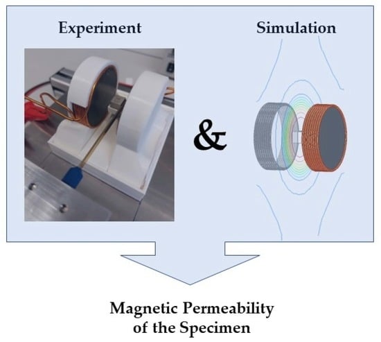
The basic concept of the experiment is to measure changes in magnetic fields outside a test object and compare them with FEM simulations to draw conclusions about the relative permeability μr within the object.
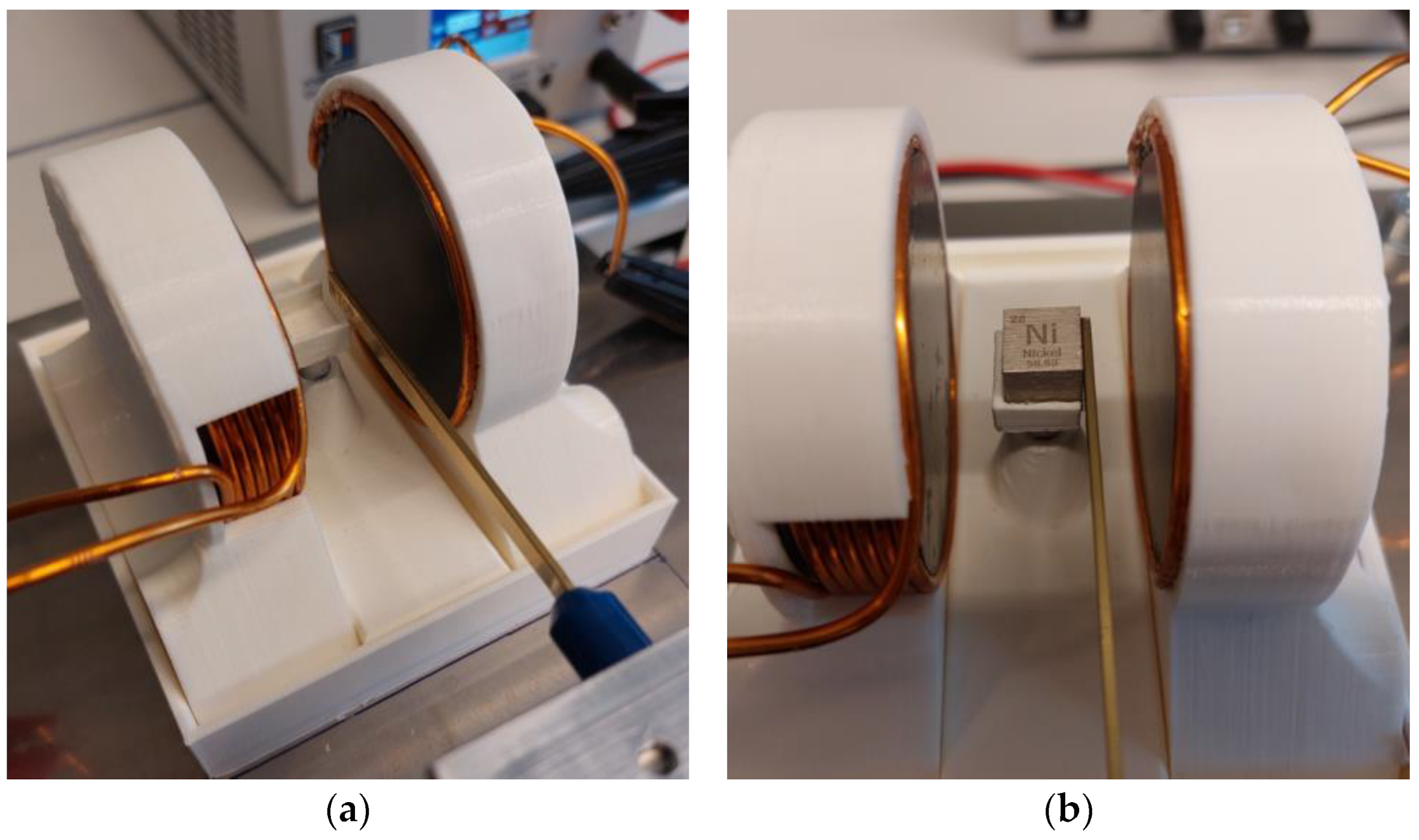
The Helmholtz coil principle is employed to generate a uniform magnetic field, which is measured using a Hall probe. To ensure that the magnetic flux is within a more measurable range, ferrite plates are positioned inside the coils. This also enhances the homogeneity of the magnetic field, making it easier to place the test object between the coils. To reduce inhomogeneities, nickel and iron cubes are used as they have planar surfaces. Non-magnetic brackets are produced via additive manufacturing and used to attach the coils and ferrites. The cubes can be positioned on a small plate at the center, as illustrated in
Figure 1.
Copper with a conductivity of σ = 58∙106 S/m was used as the coil material. The ferrite-material Fi339 was selected as the ferrite core material due to its nearly constant permeability within the range for the magnetic field lower than H < 50 A/m. The cubes are subject to a magnetic hysteresis whose behavior is unknown.
The implementation of these measures ensures a more precise and accurate measurement of the magnetic field, which in turn improves the reliability of the results obtained from the experiment. From the illustration presented in
Figure 2, one can observe the entire experimental arrangement, comprising the cross-slide table, magnetometer, and the process of data analysis carried out with the aid of a laptop.
A transverse Hall probe connected to a magnetometer measures the magnetic flux density B and can be moved manually in the x–y plane with a cross slide table. The alignment in the z-direction is preset by adjusting the height of the cube plate. According to the datasheet, when the Hall sensor touches the cube, the Hall element is 0.5 mm away from the contact surface. DC power supply with regulated current generates the static magnetic field. The measurement data collected by the magnetometer can be accessed through a USB interface and can be subsequently compared directly with the results obtained through simulations.
To determine the magnetic material properties, the measurement results are compared with a parameter study based on a magnetostatic finite element analysis. Due to the use of cubes as test objects, a 3D simulation is necessary, as seen in
Figure 3. If rotationally symmetrical test objects are used instead of cubes, the FEM model can be reduced to two dimensions.
In this case, if the boundary conditions are chosen appropriately, the geometric symmetry on the y–z plane can be used to halve the computational area. For this purpose, the magnetic field components tangential to the symmetry plane and the components normal to the outer surface of the calculation region are set to zero. The coils are modeled as separate individual windings through which the coil current flows as excitation. The hysteresis curve of the ferrite cores according to the Fi339 data sheet is integrated in the model. Based on the simulation results in the range of 1 A to 20 A, this hysteresis curve shows a nearly constant relative permeability of approximately 7200. The relative permeability of the cube was varied in logarithmic distance, from a value of 1 to 100 with 21 values, as seen in
Table 1.
To differentiate between high permeabilities during evaluation, the simulation’s energy error needs to be less than 0.005%. This results in a 3D mesh with over 6 million tetrahedrons and a simulation time over 3 h per variation. The calculation was performed with Ansys Electromagnetic Desktop 2022R2 with an AMD Ryzen Threadripper 3995wx processor.
The measurement was now carried out as follows with two different currents i1 = 5 A and i2 = 15 A. First, the magnetic field was measured for both currents without a test object and compared with the corresponding simulation. Since the windings in the experiment do not correspond exactly to the windings in the simulation and the properties of the ferrite cores are subject to a certain tolerance, these differences can be compensated for with the DC power supply. Specifically, the ends that do not completely close in the actual structure should be considered, whereas in the model all the windings are completely closed. To compensate the end effects, the current was increased by 0.1 A. Next, the cubes are placed on the central plate and the Hall probe is moved in the x-direction until they touch, and the Hall element inside the Hall probe is 0.5 mm away from the surface. Since the cubes are ferromagnetic, they have been heated beforehand so that they lose their magnetization. In y-direction, the Hall probe is moved from one corner to the other. Due to the high magnetic permeability of the ferromagnetic cube, the external homogeneous magnetic field is guided into the cube and concentrated at the edges, causing the magnetic field to be compressed at those locations. Thus, the center of the cube can be determined from the measurement of the magnetic flux density and the Hall probe can be fixed at this y-position. The alignment parallel to the z-axis between probe and object has been preset. After the position has been set, data collection can be performed for multiple currents. For each current and object, several individual measurements are taken, and the average value is calculated from them.
3. Results
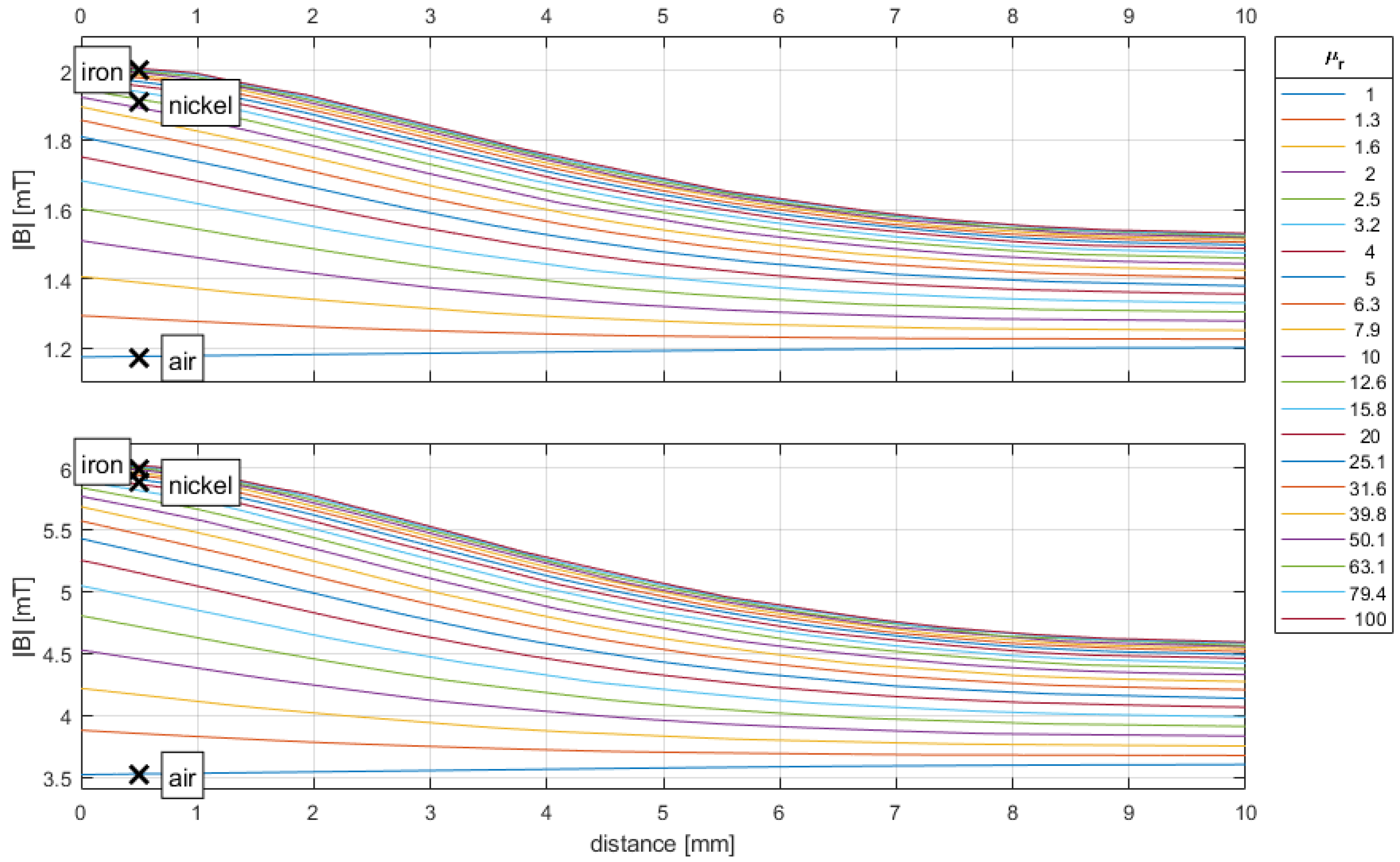
Once the data from the measurement and simulation processes have been gathered, they can be analyzed. As shown in
Figure 4, the outcome of the simulation is visually displayed in the form of a set of lines that illustrate the distance from the object surface to the ferrite core.
The value μr = 1 corresponds to an airgap between the coils without any object placed in between. In this case, no field amplification occurs, and the magnetic flux density B is at its lowest and is indicated by the bottom line. The measurement results are shown as crosses at the position of the hall element located at 0.5 mm. The measurement results for the experimental setup without any object and filled with air are in good agreement with the simulation results for both currents used in the experiment. The position x = 0 mm represents the surface of the cube, while x = 10 mm represents the surface of the ferrite core. When the permeability increases, more field lines are forced through the smaller surface of the cube, resulting in a higher magnetic flux density on the cube surface as compared to the ferrite core surface. In the absence of any foreign objects in the setup and filled with air, the field lines may expand in the middle, leading to a lower flux density.
The presence of a ferromagnetic cube significantly increases the magnetic flux density, with iron always exhibiting higher values than those of nickel. This indicates that iron is a better conductor of magnetic field lines than nickel. However, it is important to note that the behavior of the cubes is subject to magnetic hysteresis, which adds an element of uncertainty to the measurements. Nonetheless, the results demonstrate the effectiveness of the experimental setup in measuring the magnetic flux density of different materials, and the importance of material selection in achieving reliable and accurate results.
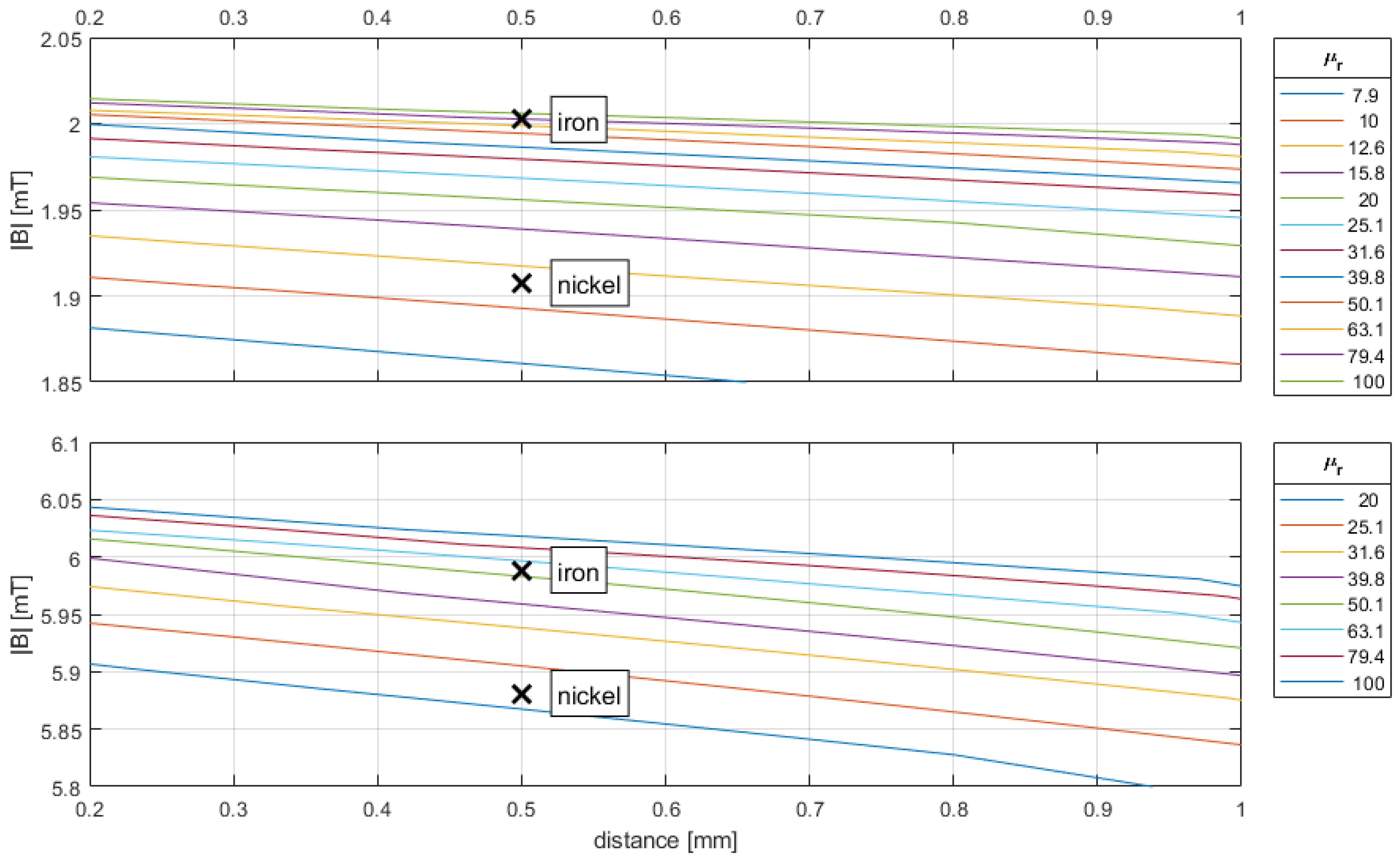
In
Figure 5, it can be observed that the relative permeability μ
r of nickel lies between 10 and 12.6 for a current of i
1 = 5 A and between 20 and 25.1 for a current of i
2 = 15 A. On the other hand, the relative permeability of the iron cube is just under 79.4 for a current of i
1 = 5 A and between 63.1 and 79.4 for a current of i
2 = 15 A.
To obtain a numeric value for the permeability of the cubes, the simulation results can be used to represent the relative permeability of the object as a function of the magnetic flux density at the measurement position, which is located 0.5 mm outside of the object. The appropriate function can be determined by curve fitting the individual simulation points. Various model functions were tested for this purpose, such as polynomial functions 8th order or gaussian functions third order. The Michaelis–Menten Equation (1), which is commonly used in biochemistry, provides the most accurate approximation, as can be seen in
Figure 6.
Both currents i
1 and i
2 yield the same parameter value of
a, which is
a = −0.6597496. For i
1 = 5 A, the value of
b is determined to be
b = −2.019155. When the current is i
2 = 15 A, the value of
b is tripled, resulting in
b = −6.057465. By substituting a measured value of the magnetic flux density
B at position
x = 0.5 into Equation (2), the relative permeability within the cubes can be determined.
Table 2 and the related
Figure 7 shows the finally determined values of the permeability inside the cube. The slight drop in the relative permeability of iron can be attributed to measurement inaccuracies. Further measurements of the iron sample, where the current is varied from 0 A to 20 A in steps of 1 A, exhibit a linear relationship between relative permeability
μr and magnetic flux density
B.
4. Conclusions
This paper presented a method for determining the relative permeability inside test-objects in magnetostatic fields. A simulation-based parameter study enables the determination of the relative permeability inside test objects by comparing field measurements outside the test object with simulation results. This represents an alternative measurement method for measuring magnetic flux density compared to the Epstein method. This method can be applied to analyze materials with varying magnetic permeability, such as stainless steel, even when the permeability is in the low range.
As shown in
Figure 3 and
Figure 4, magnetic materials with low relative permeability can be measured particularly well. Only para- and diamagnetic substances, whose relative permeability is nearly equal to 1, have too little influence on the magnetic field to allow for a reliable value to be determined. To examine the hysteresis behavior, it is necessary to increase currents through the coils to generate stronger magnetic fields within the sample. Since the magnetic flux increases for higher currents, it is important that the hysteresis behavior of the ferrite cores is well known and reproduced exactly in the FEM simulation, otherwise non-linear deviations between the simulation and measurement results will occur. The temperatures that come with the increased currents must also be considered. Either temperature-stable coils or ferrite cores must be used, otherwise a cooling system must be applied for temperature compensation.
It is important to note that the experimental prototype developed was manufactured with high tolerances. However, the measurement accuracy can be further improved by reducing the geometric tolerances, which would allow the FEM model to better match the actual measurement setup. Additionally, if the coils are not fully closed due to winding issues, this can also have an impact, but can be compensated by adjusting the current. It is crucial to ensure that the components used to attach the coils and samples do not expand or distort when heated, as this could lead to changes in distances and alignments.
To investigate frequency dependencies, alternating current can be applied to the coils. It is important to make the frame from nonconductive material to avoid the induction of eddy currents. These currents can distort the magnetic field and generate extra heat, interfering with accurate measurements.


