Abstract
An analytical study of the nonlinear response of imperfect stiffened doubly curved shells made of functionally graded material (FGM) is presented. The formulation of the problem is based on the first-order shear deformation shell theory in conjunction with the von Kármán geometrical nonlinear strain–displacement relationships. The nonlinear equations of the motion of stiffened double-curved shells based on the extended Sanders’s theory were derived using Galerkin’s method. The material properties vary in the direction of thickness according to the linear rule of mixture. The effect of both longitudinal and transverse stiffeners was considered using Lekhnitsky’s technique. The fundamental frequencies of the stiffened shell are compared with the FE solutions obtained by using the ABAQUS 6.14 software. A stepwise approximation technique is applied to model the functionally graded shell. The resulting nonlinear ordinary differential equations were solved numerically by using the fourth-order Runge–Kutta method. Closed-form solutions for nonlinear frequency–amplitude responses were obtained using He’s energy method. The effect of power index, functionally graded stiffeners, geometrical parameters, and initial imperfection on the nonlinear response of the stiffened shell are considered and discussed.
1. Introduction
For the last few decades, laminated composite materials have been extensively used in aerospace, civil, and marine engineering. They are well accepted due to their high strength-to-weight ratio, high corrosion resistivity, and very good fatigue characteristics. In many cases, the laminated plates undergo large-amplitude vibration, which may lead to delamination and crack initiation and create thermal stresses between layers. Their multilayer compositions and bonding phenomenon make them vulnerable to a mismatch of mechanical properties across the interfaces [1]. Recently, functionally graded materials (FGMs), a new type of composite material, have been introduced to overcome these drawbacks. The material design of FGMs has mechanical properties varying smoothly from one surface made of metal to another made of ceramic at the micron level [2].
In recent years, several studies have been conducted on the dynamical analysis of FGM plates and shells. Hashemi et al. [3] studied the effects of aspect ratios, gradient indices, and stiffness coefficients on the free vibration of functionally graded plates using first-order shear deformation theory (FSDT). Six combinations of boundary conditions were studied in their paper. Higher-order shear deformation theory (HSDT) and a meshless approach were adopted by Xiang et al. [4] to calculate the natural frequency of the functionally graded plates.
Cylindrical panels are found mainly in spacecraft, submarines, missiles, and other aircraft components, e.g., fuselage sections. To study the nonlinear vibration of stainless steel and nickel cylindrical shells, Strozzi and Pellicano [5] adopted the Sanders–Koiter theory. Their study was based on two steps: linear analysis to find the eigenfunctions and then nonlinear analysis based on the previously calculated functions. Pradhan et al. [6] derived the governing equations using Rayleigh’s method. The natural frequencies of the functionally graded cylindrical shells were evaluated based on Love’s shell theory. Then Pradhan et al. [6] extended their previous study to include different volume fraction indices and various boundary conditions. Shah et al. [7] adopted the Rayleigh–Ritz approach to find the linear natural frequencies of FGM thin cylindrical shells. By ignoring the shallowness of cylindrical shells, Bich and Xuan [8] introduced an improved Donnell shell theory to study the nonlinear vibration of functionally graded circular cylindrical shells. A very good agreement was observed comparing their results by using commercial software. Yang and Shen [9] studied the natural frequencies and the unstable regions of the functionally graded cylindrical panels under mechanical and thermal loads. Patel et al. [10] conducted a parametric study on the free vibration analysis of functionally graded elliptical and cylindrical shells using a finite element method based on a higher-order displacement model. Golpayegani et al. [11] investigated the free vibration behavior of functionally graded cylindrical shells with linearly varying thickness using the finite element method, analyzed the effects of geometric and material parameters under various boundary conditions, and validated the results against existing analytical solutions.
A generalized formulation of doubly curved shells, including two radii of curvature, has been considered in some papers. For example, Alijani et al. [12] studied the nonlinear forced vibration of simply supported FGM doubly curved shallow shells based on Donnell’s shell theory. In his study, to obtain numerical solutions, energy function was reduced to a system of infinite nonlinear ordinary differential equations (ODEs) using Galerkin’s method. Bich and Long [13] studied the nonlinear vibration and dynamical buckling of FGM cylindrical and doubly curved shallow shells subjected to mechanical load using the classical shell theory (CLPT). Matsunaga [14] presented a 2D higher-order theory to evaluate natural frequencies, stress distributions, and buckling stresses of a simply supported functionally graded shallow shell. Zannon et al. [15] analyzed the free vibration of functionally graded thick spherical shells using radial basis functions and third-order shear deformation theory, with numerical results validating the method for simply supported and clamped edge conditions. Sayyad et al. [16] analyzed the static and free vibration behavior of functionally graded material (FGM) sandwich shallow shells with double curvature, specifically hyperbolic and elliptical paraboloids, using various shell theories and a unified formulation and provided new insights and validated numerical results for different geometries and material configurations. A novel finite element model based on the improved first-order shear deformation theory to investigate the vibration behavior of functionally graded doubly curved shallow shells was studied by Benounas et al. [17]. This approach demonstrated its accuracy through comparison studies and conducted a comprehensive parameter analysis to inform future shell structure design and research.
In addition to discussing the unstiffened structures, the study of stiffened plates and shells is very significant and should be considered, merely because they are more realistic and have been utilized in the aerospace industry. Most of the following studies are based on the Lekhnitsky smeared technique. For example, Bich et al. [18] conducted a geometrically nonlinear vibrational analysis of eccentrically stiffened functionally graded double-curved shells based on FSDT under mechanical load. Duc [19] studied the nonlinear dynamic response of the stiffened FGM double-curved shallow shells being subjected to both transverse and compressive loads. Bich et al. [20] used the classical shell theory and the smeared stiffeners technique to study the nonlinear vibration and dynamic buckling of stiffened functionally graded cylindrical panels. The influence of the volume fraction index and the initial imperfection were taken into account in this study. Rahimi et al. [21] evaluated the vibrational behavior of ring-supported functionally graded cylindrical shells based on Sanders’ thin shell theory. Ritz method is used to derive the governing equations of motion. The influence of some boundary conditions was considered. Dung et al. [22] adopted a theoretical formulation in terms of displacement components based on Reddy’s third-order shear deformation theory (TSDT) to analyze the dynamic response of stiffened cylindrical shells made completely of FGM and filled inside by elastic foundations. Minh et al. [23] investigated the nonlinear vibration and dynamic responses of functionally graded graphene-reinforced composite stiffened panels under uniform temperature variation using advanced modeling techniques, numerical methods, and theoretical formulations. Bich et al. [24] presented a semi-analytical approach to investigate the nonlinear dynamic behavior of orthogonally stiffened functionally graded shallow shells using the classical thin shell theory. The effect of damping, mechanical, and critical buckling loads were taken into account in this work. Wattanasakulpong and Chaikittiratana [25] used the power law distribution and Mori–Tanaka homogenization scheme to define the material variational through the shell thickness. In their paper, stiffened shells with various radii of curvatures were considered in the evaluation of the nonlinear frequencies. A MATLAB-based and a COMSOL finite-element model were developed by Singh et al. [26] to estimate, for the first time, the free vibration characteristics of stiffened functionally graded folded plates in a hygrothermal environment, revealing significant effects of temperature and moisture on their dynamic behavior.
In all the above papers, the frequency responses of a Duffing equation were obtained numerically. Analytical solutions were found only in cases of weak nonlinearities. In contrast, the current work develops a closed-form solution for the amplitude–frequency relationship of a Duffing equation characterized by strong quadratic and cubic nonlinearities, using He’s energy balance method. The theoretical innovation lies in the tailored application of He’s method to simultaneously handle both quadratic and cubic terms, which typically complicate analytical treatment. Unlike conventional approaches, this formulation provides an explicit relationship that accurately captures nonlinear dynamic behavior without requiring numerical iteration. The solution’s accuracy is further supported by detailed parametric analyses, which offer critical insights into the effects of nonlinear stiffness coefficients on resonance characteristics. In addition to these analytical advancements, this study accounts for the contributions of both longitudinal and transverse stiffeners, using Lekhnitsky’s smeared technique, as well as their torsional effects, an aspect frequently neglected in prior works. Several cases with different volumetric fractions and parameters were analyzed to validate the accuracy of the proposed technique. Overall, this paper offers a robust analytical framework for understanding complex nonlinear oscillations in mechanical and structural systems and serves as a benchmark for future analytical and numerical studies in nonlinear dynamics.
2. Functionally Graded Double-Curved Shells
2.1. Modeling
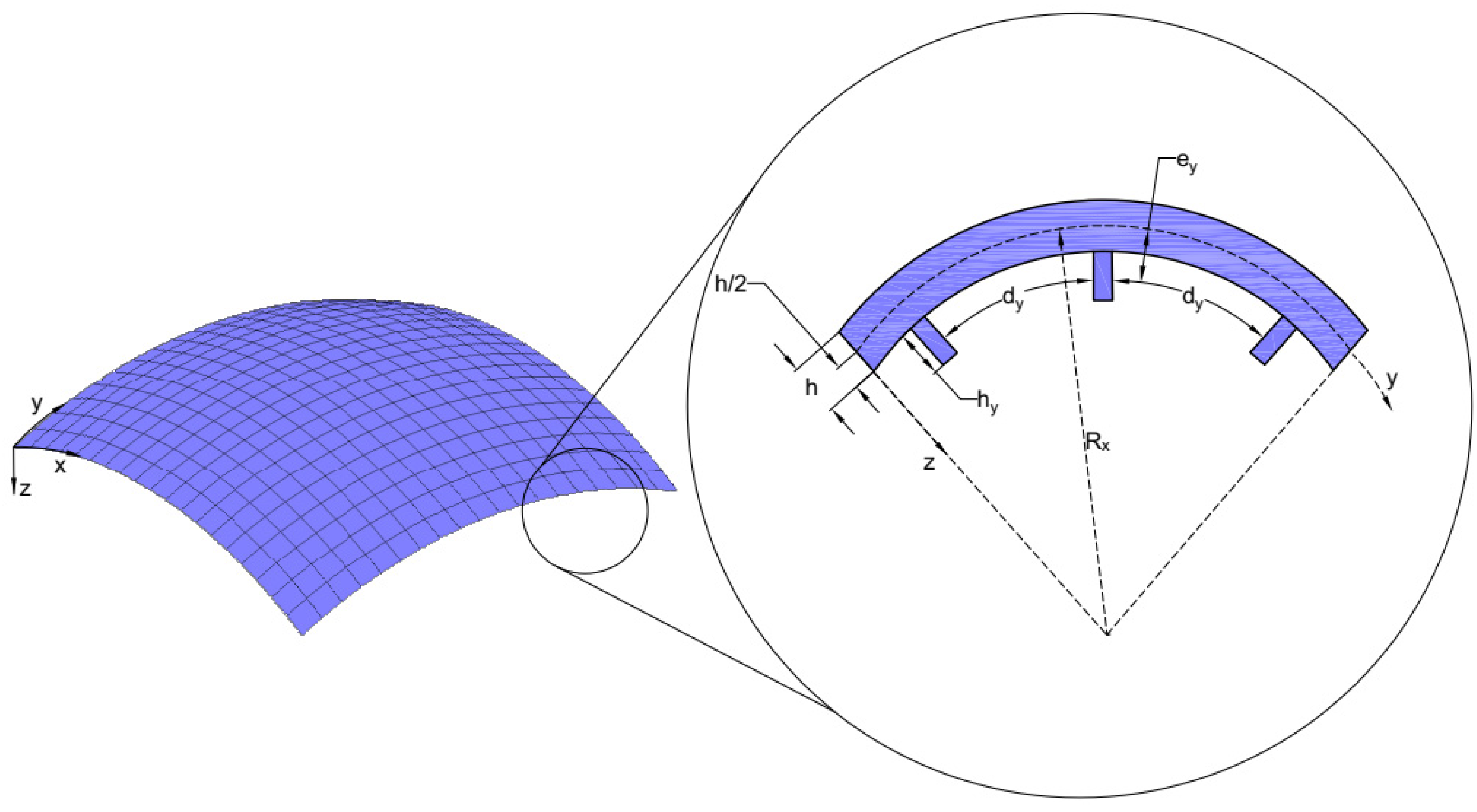
Consider an eccentrically stiffened, doubly curved, shallow shell made from functionally graded materials (FGM). The shallow shell is assumed to have a small rise-to-span ratio. In general, the middle surface of the shells should be defined by using curvilinear coordinates. But that is not the case with shallow shells. Here, the Cartesian coordinates (x, y, z) are established in which (x, y) define the plane of the middle surface and z on the thickness direction . The Cartesian coordinates, the radius of curvature Rx, and the configurations and dimensions of the transversal stiffeners are shown in Figure 1 below.
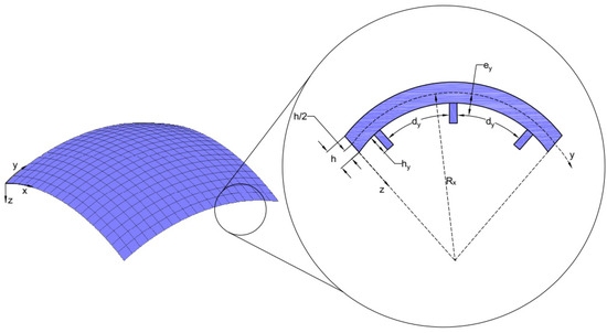
Figure 1.
A double-curved shell with configurations and dimensions of transversal stiffeners.
For the stiffeners in the x and y directions, dx and dy are the spacing between two consecutive longitudinal and transversal stiffeners, respectively. The values bx and by represent the width, and hx and hy represent the thickness. Finally, ex and ey are the eccentricities of the stiffeners with respect to the middle surface of the shell.
2.2. Material Properties
Functionally graded material consists of a mixture of metal (denoted by “m”) and ceramic (denoted by “c”). The top surface of the shell is considered to be metal and the bottom surface to be ceramic. To provide continuity between the shells and the stiffeners, it is assumed that the stiffeners are made of full metal when placed on the metal-rich side of the shell and made of full ceramic when placed on the ceramic-rich side. The volume fractions of ceramic and metal of the FGM shells and stiffeners are assumed to change through the thickness according to the power-law distribution [27]:
where , and are the volume fraction indices that define the material distribution and , and are the total thicknesses of the shells and stiffeners. In this paper, the FGM properties, , are assumed to be functions of the volume fractions and are related to the volume fractions and by the linear rule of mixture (Voigt’s model) as follows [27]:
where represents the Young’s modulus , the mass density , and the Poisson’s ratio .
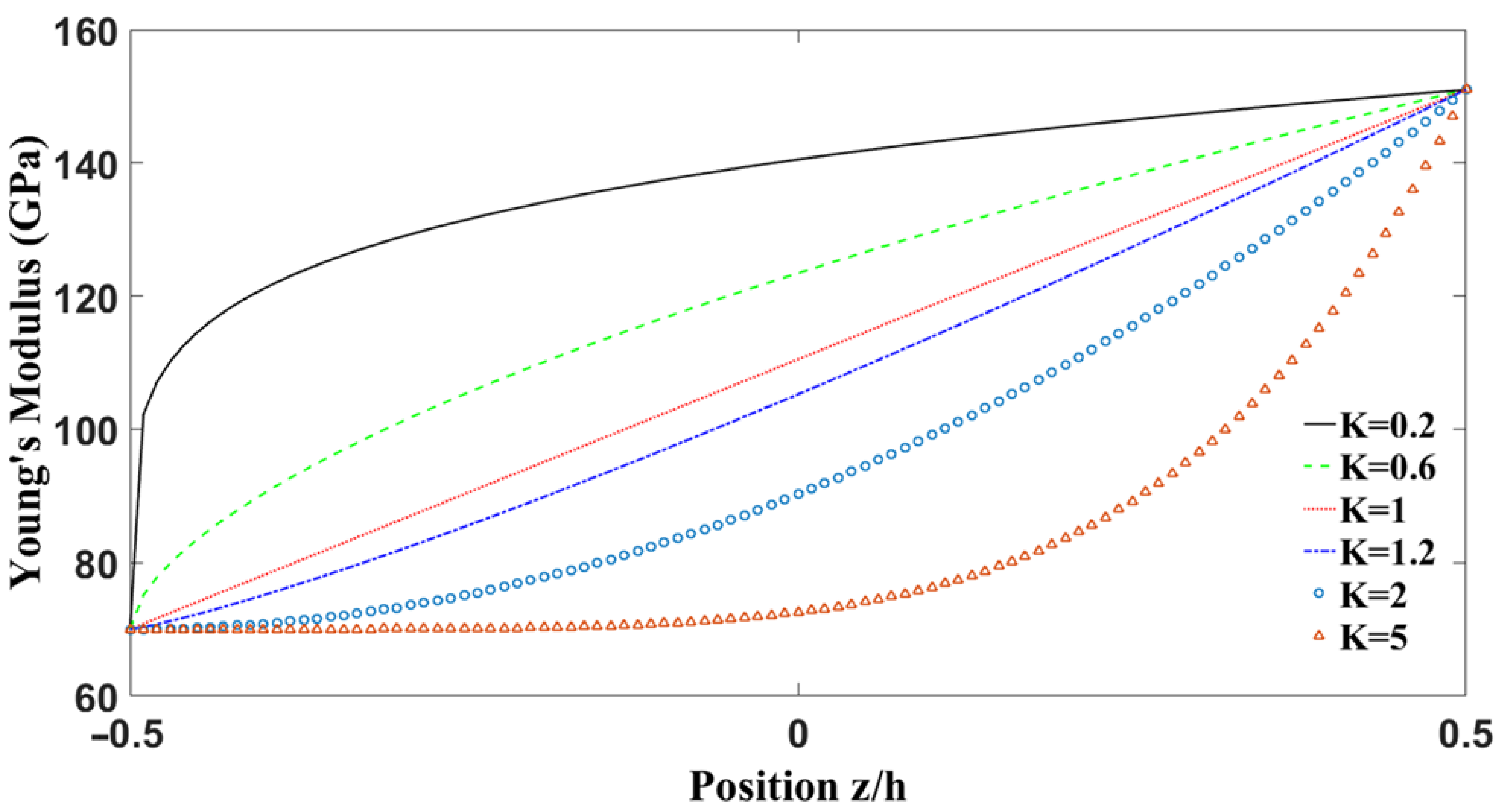
Figure 2 shows the variation of the modulus of elasticity of aluminum and zirconia ( FG shells with respect to the thickness for different power law indices. It can be seen that the Young’s modulus is smaller when the Ks are smaller.
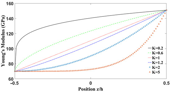
Figure 2.
Young’s modulus variations with respect to the dimensionless thickness of the shell for different volume fraction indices
3. Theoretical Formulation
3.1. Governing Equations
The displacement field based on the first-order shear deformation theory (FSDT) is defined as follows:
The FSDT requires a shear correction factor that depends not only on the geometric parameter of a structure but also on the boundary conditions and the applied load. In the case of isotropic and laminated composite shells, the shear correction factor is , but in the case of functionally graded materials, can be expressed as given by [28]:
Using the von Kármán type geometrical nonlinearity with imperfection and Sanders’s shell theory, the nonlinear strain–displacement relationship for a double curved shallow shell is given by [29] as follows:
where and are the normal strains, is the in-plane shear strain, are the transverse shear deformation, and is the initial shell imperfection, which represents a small deviation of the shell middle plane.
3.2. Constitutive Relations
The stress–strain relations by Hooke’s law for a functionally graded shell are defined as follows [25]:
where , , and .
It is assumed that the stiffeners are perfectly bonded to the FGM shell; therefore, the normal strain components of the double curved shell are similar to the skin. Hence, the stress–strain relations of the stiffeners in both the x and y directions can be written as follows [22]:
where , are the shear moduli of the stiffeners in the x and y directions, respectively. For the case of numerous identical and closely spaced stiffeners, the contribution of the stiffeners can be accounted for by using the “Lekhnitsky smeared stiffeners technique”. In other words, the effect of the stiffeners is assumed to be smeared over the skin where the twisting of the stiffeners is also included. The forces and moment resultants of the FGM stiffened double-curved shell under temperature are obtained by integrating their normal and shear stresses over its thickness as follows [30]:
Substituting Equations (6)–(8) into Equation (9) yields the constitutive relations as follows:
where the equivalent shell stiffness for a reinforced shell is
and are the shear moduli, and are the effective torsional constants, and are the second moment or area of the stiffeners with respect to the x and y axes, respectively, and are expressed as follows:
Matrices A, B, , and D represent the extensional, bending–extensional coupling, transverse shear, and bending stiffness, and are expressed as follows:
The expression of the force and moment resultants in Equation (10) can be expended and written in terms of displacements:
3.3. Equation of Motion
The nonlinear equations of motion for the imperfect eccentrically stiffened functionally graded doubly curved shell based on Sanders’s shell theory that accounts for the shear deformation are expressed as follows [25]:
where and , and are uniformly distributed pressures over the shell surface in the x, y, and z directions. are calculated by the following:
In order to investigate the dynamic movement of the stiffened doubly curved shell under mechanical load, the governing equations are required to be written in terms of displacements. By substituting Equation (14) into Equation (15), one can obtain the following:
where are the linear operators and are the nonlinear operators.
4. Solution Procedures
It can be seen that Equation (17) shows a high coupling between displacements and rotations. In order to solve the above coupled equations, some trigonometric series are used. Suppose that all four edges are simply supported and restrained from moving, in other words, all edges are immovable, then the following conditions are encountered [31].
The geometric boundary conditions given by Equation (18) are satisfied identically by employing the following doubly Fourier series equations:
where m and n denote the number of half waves in the x and y directions, respectively. The terms are the generalized coordinates, which are the unknown functions of time, t, and the coefficient, varying between 0 and 1, represents the size of the imperfection .
Furthermore, the external force for the static case can be expressed in the form of double trigonometric series as follows [29]:
The coefficients for the case of a uniformly distributed load are defined as follows:
where is the amplitude of the excitation. For the case of a sinusoidally distributed load:
Finally, for the case of a concentrated load:
Substituting Equations (19) and (20) into equations of motion (17) and then applying Galerkin’s method, five equations will be obtained in terms of the time-dependent variables as follows:
4.1. Linear Vibration Analysis Solution
By taking only the linear terms of Equation (24), and neglecting the effect of damping and imperfection, the equations above of motion can be written in a matrix form as follows:
Solving the resultant determinant leads to five frequencies. The smallest one of which is called the fundamental frequency.
4.2. Solution of Nonlinear Static Equations
Consider the FG double-curved shell with all four edges simply supported and subjected to a uniform external transverse load without any imperfection, damping effects, and inertial forces. After considering the assumptions above, the static deflection is determined by setting all the time derivative terms in Equation (24a), Equation (24b), Equation (24d) and Equation (24e) equal to zero and solving the resulting equations in terms of displacement components Then substituting the results into Equation (24c) without the time derivatives (static equation) to obtain the static–deflection curves of the eccentrically FGM double-curved shells:
Note that in Equation (26) is not a function of time and is given either by Equation (21), Equation (22), or Equation (23).
4.3. Solution of Nonlinear Dynamic Equations
For this case, Huy Bich [18] and Kobayashi and Leissa [32] investigated the effect of inertia terms on nonlinear vibration. It was shown that neglecting both the in-plane and rotational inertia terms did not cause significant errors. Hence, solving Equation (24a), Equation (24b), Equation (24d) and Equation (24e) for and then substituting the results into Equation (24c), the nonlinear dynamic response of a stiffened FG double-curved shallow shell, also known as the extended Duffing equation, will be obtained. Note that the original Duffing equation contains only a cubic nonlinear term, whereas the extended Duffing equation includes the quadratic term in addition to the cubic term as follows:
where is the global mass, is the damping coefficient, is the linear stiffness, are coefficients of the nonlinear quadratic and cubic terms (nonlinear stiffness), respectively, and is the imperfection coefficient.
For the case of a perfect structure, the extended Duffing equation above becomes the following:
Nonlinear responses of Equations (28) and (29) are investigated using the fourth-order Runge–Kutta numerical method combined with the following initial conditions:
4.4. Amplitude–Frequency Curve
The nonlinear amplitude frequency response of the stiffened double-curved shell is studied. The harmonic balance method was applied using single and multi-harmonic terms, and the He’s energy balance is considered to obtain a closed-form solution for the strongly nonlinear Duffing equation.
4.4.1. Nonlinear Forced Vibration for Isotropic Shells
Nonlinear vibration of the stiffened FGM double-curved shell is considered under uniformly distributed pressure . To obtain a closed-form frequency–amplitude response of nonlinear forced vibration, the harmonic balance method is applied. Only a single harmonic term is used for isotropic shells. The excitation is assumed to be harmonic of the form . The response is assumed to be . Using Galerkin’s method by multiplying Equation (27) by , respectively, then integrating both results over the period of nonlinear oscillation, the equation of the amplitude–frequency curve of nonlinear forced vibration with imperfection is expressed as follows:
For the case of a perfect shell, the forced nonlinear amplitude–frequency curve above becomes the following:
4.4.2. Nonlinear Free Vibration of Isotropic Shell
For the nonlinear free vibration, we neglect the damping coefficient as well as the external loads in Equation (27) above. In this case, the frequency–amplitude equation for nonlinear free vibration with imperfection will be given as follows:
For the case of a flat shell (a panel), the free nonlinear amplitude–frequency equation above becomes the following:
4.4.3. Nonlinear Free Vibration of FGM Shell
In order to explore the effect of both quadratic and cubic nonlinear terms in the frequency response, multi-term harmonic balance method needs to be used to study the free vibration behavior of an FGM shell. Therefore, a four-term periodic solution such as the following is used:
where are neglected because they are considered too small compared to . Substituting Equation (33) into Equation (27) after neglecting the applied load gives the following expression of the frequency variation with respect to the amplitude:
4.4.4. Nonlinear Forced Vibration of FGM Shell
In order to find a closed form solution for the strongly nonlinear Duffing equation above, He’s energy balance method is adopted [33]. A variational principle of extended Duffing Equation (27) is calculated, then a Hamiltonian is developed. From which the frequency response is obtained by adopting the collocation method [34]. The amplitude–frequency relationship can be expressed as follows:
5. Numerical Results Validation and Discussion
In this section, natural frequency, nonlinear static, and dynamic analysis of simply supported stiffened and unstiffened functionally graded materials doubly curved shell with different geometric parameters and material power law indices under different mechanical loads are analyzed and validated. Throughout this paper, we consider a metal-ceramic FGM shell that is made of either aluminum and alumina ( or stainless steel and silicon nitride ). As previously stated (Section 2.2), the FGM properties in this study were assumed to depend on the volume fraction. The volume fractions of ceramic and metal in the FGM shells and stiffeners were considered to vary through the thickness based on a power-law distribution. The material properties of the selected metal and ceramic used to fabricate the FGMs are listed in Table 1.

Table 1.
Material properties of the FGM shell.
5.1. Natural Frequency Results
A comparison of the dimensionless frequency of simply supported aluminum and alumina ( double-curved shallow shells for various volume fraction indices and radii of curvature are calculated in Table 2. The obtained results are compared with those presented by Bich [24] based on classical thin shell theory, by Chorfi and Houmat [35] using the first-order shear deformation theory, and by Quan and Duc [34] based on the higher-order shear deformation theory.
Table 2.
Comparison of the fundamental natural frequency parameter for FGM double-curved shallow shells (a/b = 1, b/h = 10).
The fundamental natural frequencies (rad/s) of stiffened and unstiffened Al/Al2O3 FGM spherical panels are shown in Table 3 below. The stiffeners are made of alumina ceramic and Poisson’s ratio is chosen to be 0.3. A good agreement can be witnessed with comparison to those obtained by Bich [24] based on the classical plate theory. The natural frequencies of the stiffened spherical shells are greater than those of unstiffened shells. The natural frequencies are dependent on the volume fraction index. They decrease as the power indices increase. This is very reasonable due to the fact that the values of the elasticity modulus decrease as K increases.
Table 3.
The fundamental frequencies of the natural vibration (rad/s) of stiffened and unstiffened Al/Al2O3 spherical panels ().
To illustrate the accuracy of the proposed approach of stiffened isotropic and FGM double-curved shallow shells based on the Lekhnitsky smeared stiffeners technique, the first three natural frequencies (rad/s) of stiffened and unstiffened aluminum and zirconia FGM rectangular panels are calculated and shown in Table 4 and Table 5, respectively.
Table 4.
Natural frequency of a rectangular aluminum plate with longitudinal, transversal, and orthogonal stiffeners
Table 5.
Natural frequency of a rectangular Al/ZrO2 plate with longitudinal, transversal, and orthogonal stiffeners (
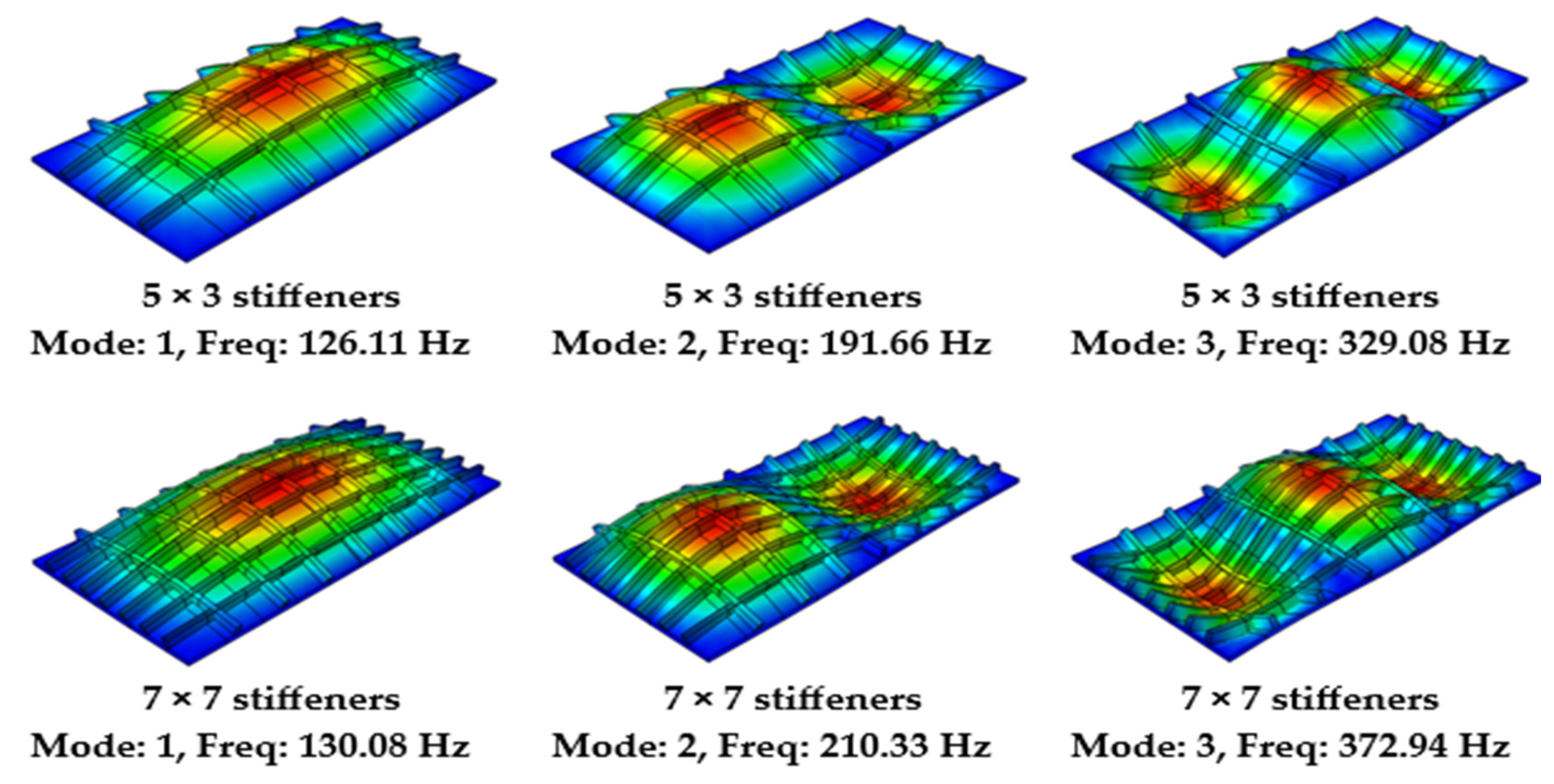
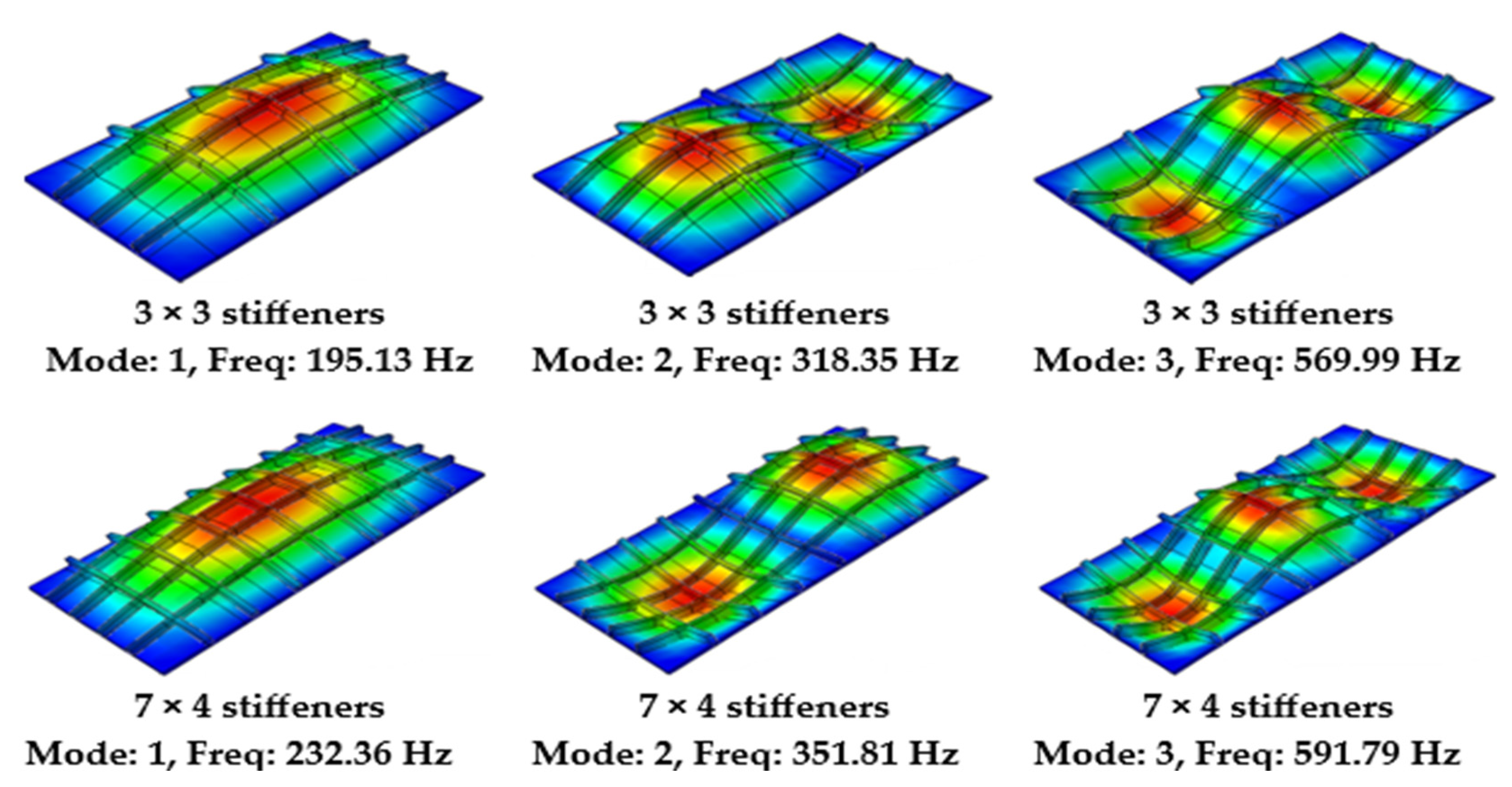
The stiffeners are made of aluminum and Poisson’s ratio is chosen to be 0.3 for simplicity. The results are compared with the FE solutions obtained by ABAQUS 6.14 software using the eight-node doubly curved shell element (S8R). A step wise approximation is applied to model the material property gradations of the rectangular FGM. To accomplish the convergence of the results, the thickness is divided into 160 layers where the stiffness matrix for each layer is calculated and then assigned at the centroid of each specific layer. Figure 3 and Figure 4 show the mode shapes of the aluminum and FGM plates with different stiffener configurations. A strong agreement is observed between the calculated results and the finite element (FE) solutions, validating the calculations performed thus far.

Figure 3.
Frequency and mode shapes of a stiffened rectangular aluminum plate using ABAQUS.

Figure 4.
Frequency and mode shapes of a stiffened rectangular Al/ZrO2 plate using ABAQUS.
5.2. Nonlinear Static Analysis
The nonlinear static analysis of a mechanically loaded, simply supported, functionally graded, doubly curved shell made of aluminum (Al) and zirconia (ZrO2) with a different power index K is considered. The shell is under static bi-sinusoidal transverse loading. Table 6 shows the non-dimensional deflection of a plate formulated based on classical plate theory (CPT) and first-order shear deformation theory (FSDT) obtained by Carrera [36], and higher-order shear theory (HSDT) obtained by Parandvar and Farid [37]. It can be seen that our results are in excellent agreement with the one based on FSDT in the following table.
Table 6.
Comparison of the non-dimensional deflection of a simply supported plate under static bi-sinusoidal transverse loading
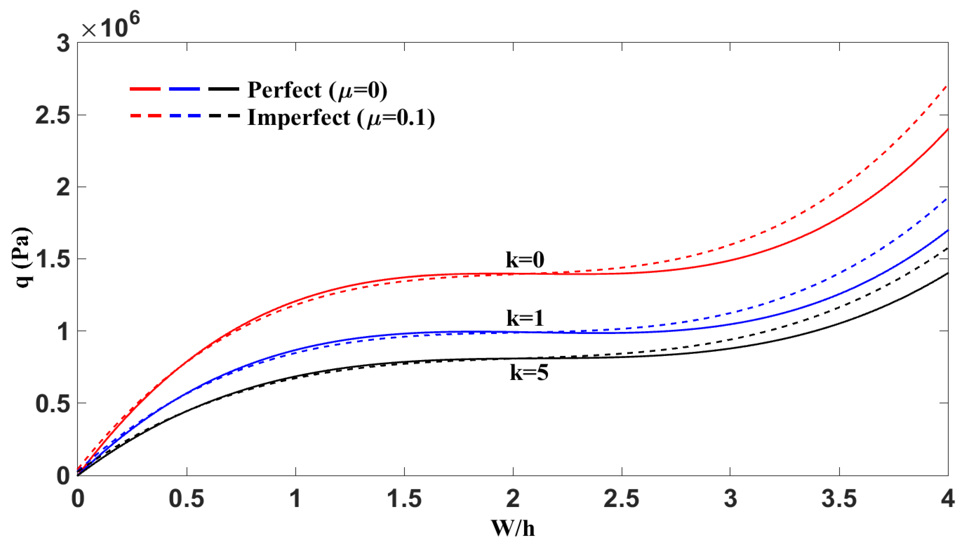
Figure 5 shows the nonlinear variation of the mechanical load q with respect to the dimensionless maximum deflection W/h for various power-law indices k = 0, 1, and 5. Both perfect (μ = 0) and imperfect (μ = 0.1) panel configurations are considered. The analysis showed that increasing the power-law index k led to a reduction in load-bearing capacity for the same deflection, indicating that higher k values, which correspond to softer material gradation in functionally graded materials, result in lower structural stiffness. Additionally, the presence of initial imperfections consistently decreased the structural capacity, with imperfect panels showing higher deflections under the same loading compared to their perfect counterparts. All the curves exhibited strongly nonlinear behavior, particularly for lower k values. This plot emphasized the significant role of both material gradation and geometric imperfections in the panels’ nonlinear mechanical response. Remarkably, as the volume fraction index increased, the response curves became less nonlinear and more stable, and the snap-through behavior transitioned into a smoother, more gradual response.
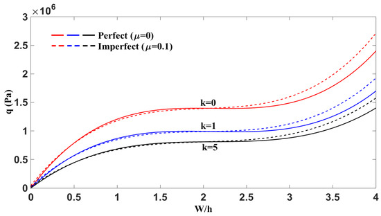
Figure 5.
Effect of volume fraction exponent k and imperfection µ on the nonlinear response of cylindrical panels (a/b = 1.1, b/h = 50, h = 0.01, a/Ry = 0.5).
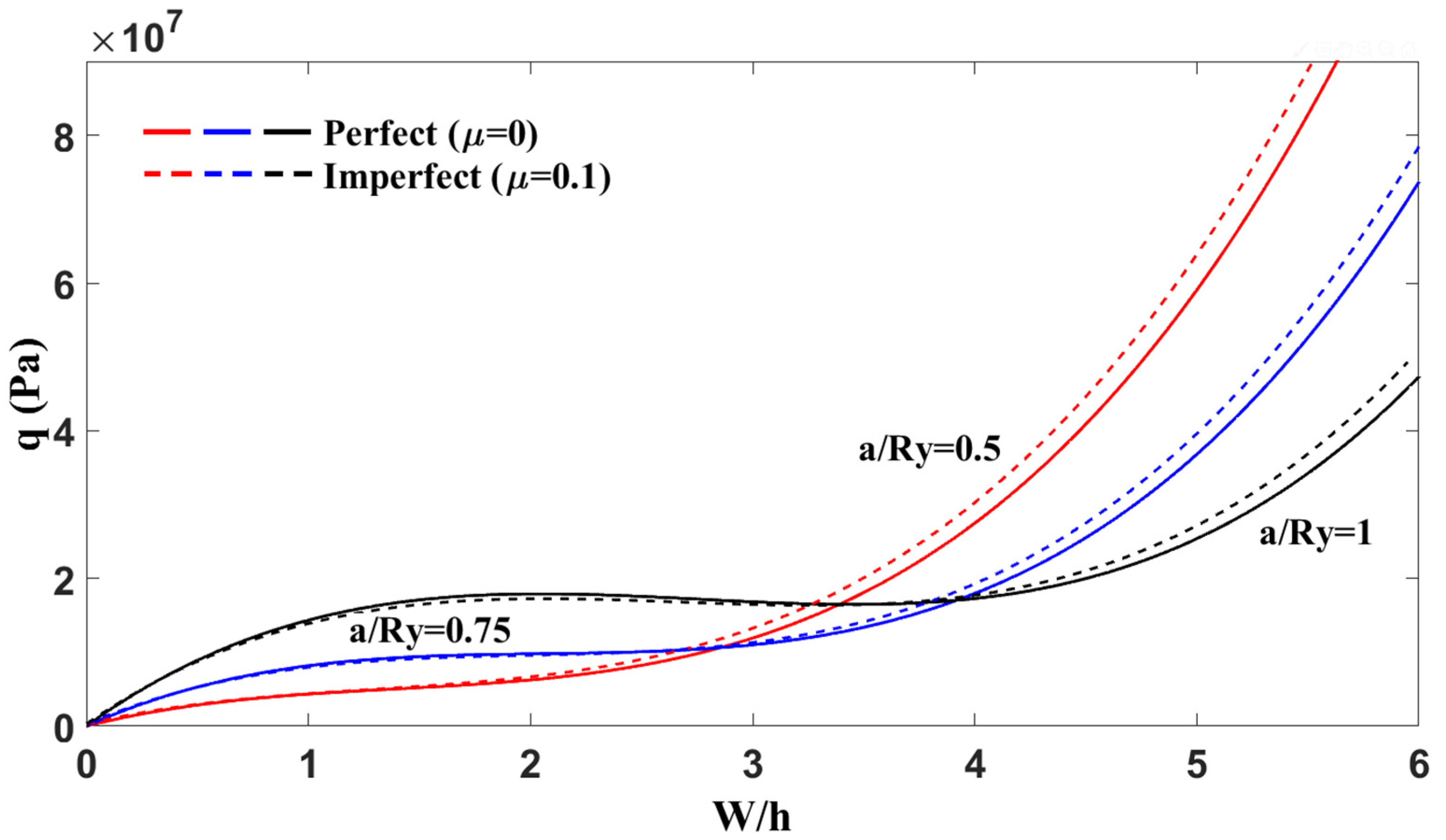
The nonlinear mechanical response of cylindrical panels shown in Figure 6 was examined by analyzing the variation of mechanical load q with respect to the dimensionless maximum deflection W/h for different length-to-radius ratios a/Ry = 0.5, 0.75 and 1, under both perfect (μ = 0) and imperfect (μ = 0.1) conditions. The results demonstrated that panels with lower a/Ry values (i.e., higher radius of curvature) become shallower and exhibit significantly higher stiffness and load-bearing capacity, as evidenced by the steeper rise in their load–deflection curves. On the contrary, increasing the a/Ry ratio led to a more flexible structural behavior and a smoother, more gradual nonlinear response. The presence of initial imperfections further reduced the structural stiffness across all cases, with imperfect panels consistently showing greater deflections under the same loading. Additionally, the snap-through response became less abrupt and more stable as the curvature decreased, highlighting the important role of geometric parameters and imperfections in the nonlinear performance of cylindrical panels.
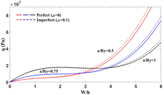
Figure 6.
Effect of the length-to-radius ratio and imperfection µ on the nonlinear response of cylindrical panels (a/b = 1, b/h = 30, K = 1).
5.3. Nonlinear Dynamic Analysis
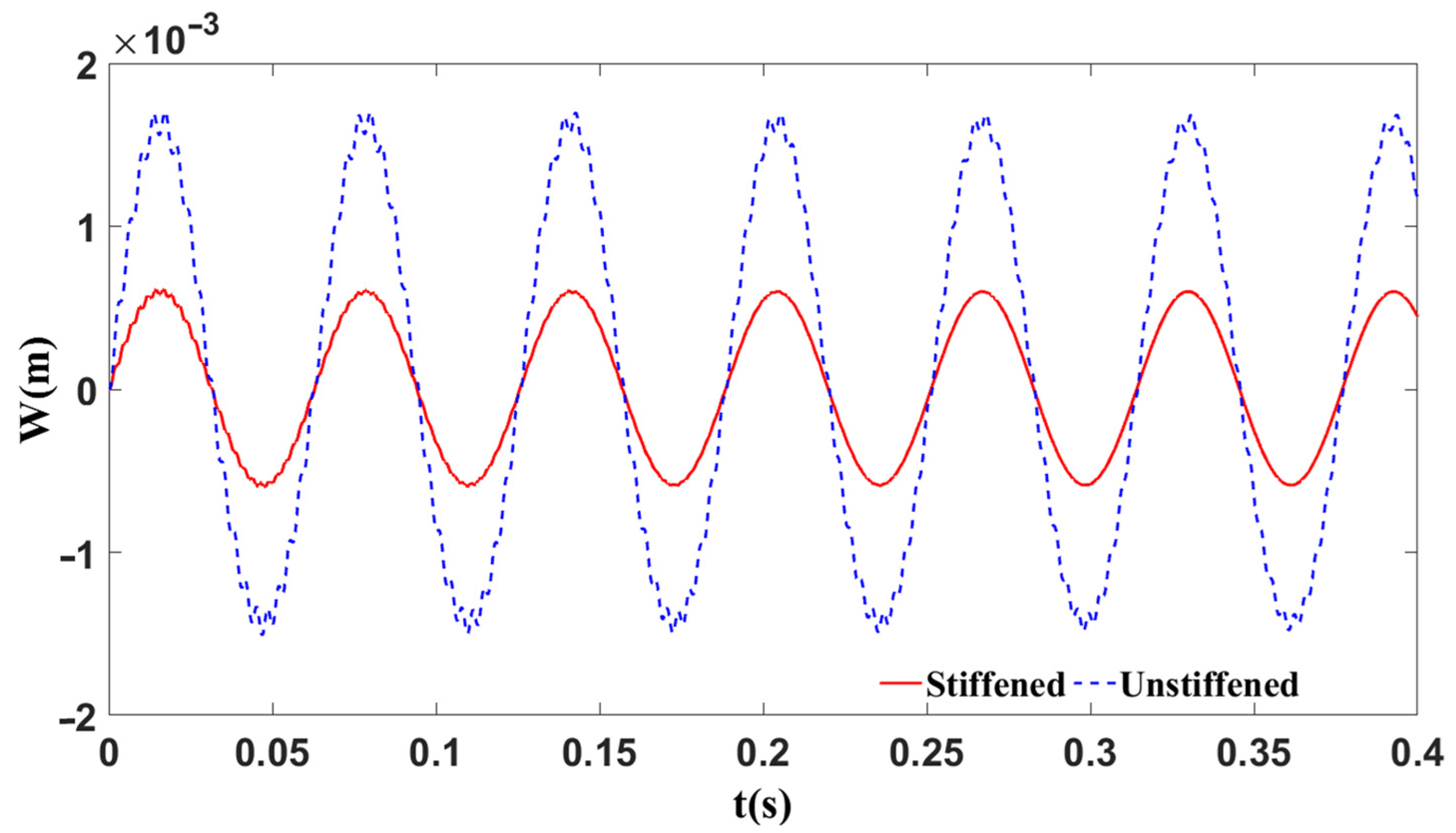
The nonlinear dynamic analysis of an eccentrically stiffened functionally graded material double-curved shallow shell subjected to a mechanical load is calculated. The shell is made of aluminum (Al) and alumina (Al2O2) and the stiffeners are made of alumina. Both longitudinal and transversal stiffeners are assumed to be identical. The nonlinear response is solved by using the fourth-order Runge–Kutta method with 3000 steps to reach convergence. Figure 7 below illustrates the nonlinear dynamic responses of stiffened and unstiffened spherical panels under sinusoidal mechanical excitation . The results showed that the unstiffened panel exhibited significantly larger vibration amplitudes, reaching nearly while the stiffened panel maintained displacements below . This substantial reduction in amplitude for the stiffened panel highlights the effectiveness of structural stiffeners in enhancing dynamic stability. Although both configurations demonstrated similar vibration frequencies, the overall response was distinctly nonlinear, particularly for the unstiffened panel. The findings emphasize the critical role of stiffening elements in reducing nonlinear oscillations and improving the structural integrity of spherical panels under dynamic loading conditions.
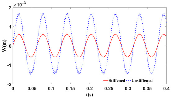
Figure 7.
Nonlinear responses of stiffened and unstiffened spherical panels
5.4. Nonlinear Frequency Response
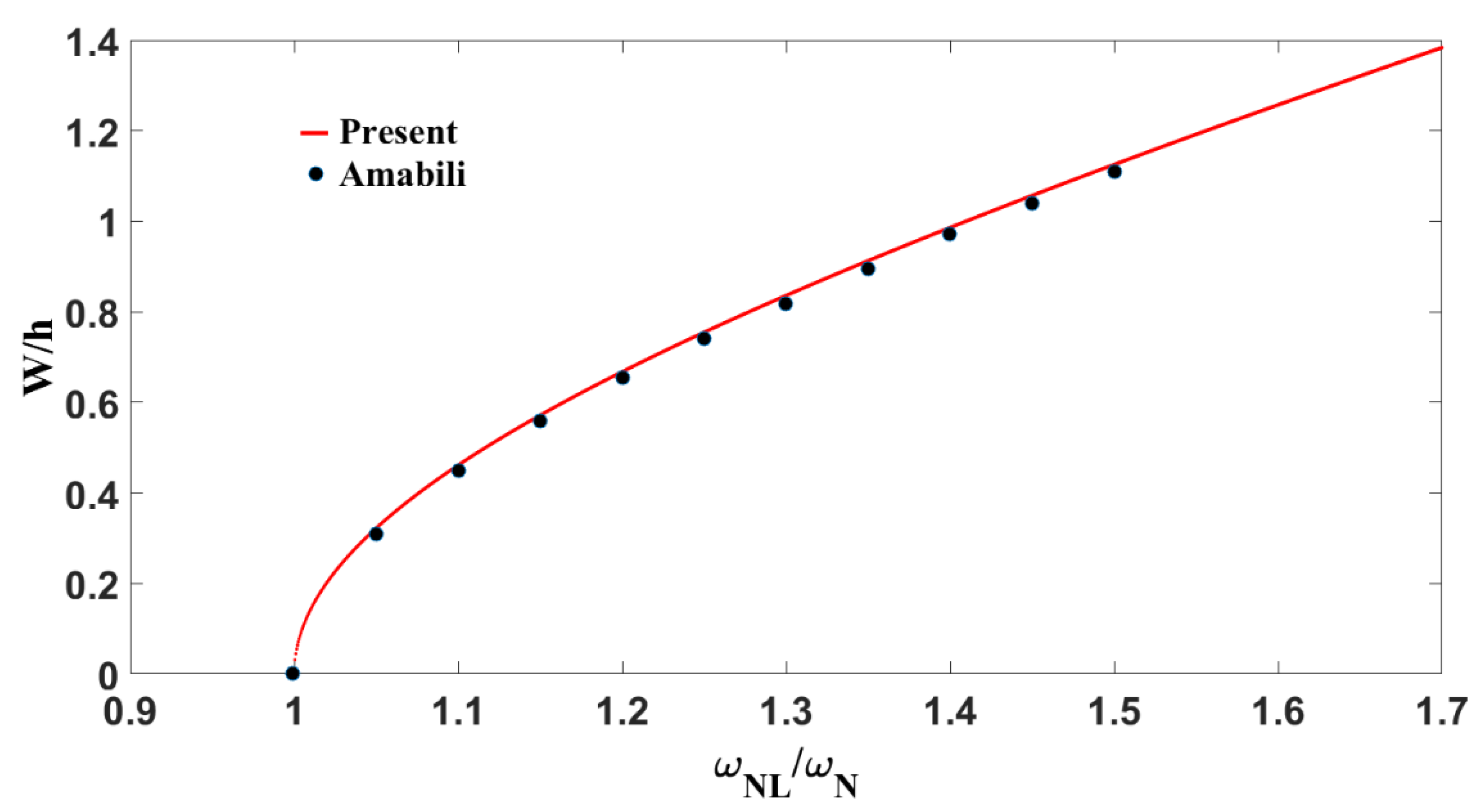
In order to validate the present solution technique, the results for nonlinear frequency–response obtained here are compared with previously published papers in this area. For this purpose, several examples are considered here. The first study was performed for a simply supported aluminum square plate with immovable edges. The so-called “backbone” obtained (frequency–amplitude curve of nonlinear free vibration) is compared with the one obtained by Amabili [38] as seen in Figure 8. The present results are in excellent agreement with the reference data from Amabili, confirming the accuracy of the developed model in capturing large-amplitude vibration behavior. The curve demonstrates a clear hardening-type nonlinear response, where the frequency increases with deflection due to geometric stiffening effects. For small deflections the plate exhibits linear behavior with . As the deflection increases to moderate levels ( W/h, the system transitions into a nonlinear regime characterized by in-plane stretching and increased stiffness. Beyond , strong geometric nonlinearity dominates, resulting in a frequency shift. This nonlinear stiffening is critical in the dynamic analysis of lightweight structural components, where neglecting such effects may lead to inaccurate predictions of resonance conditions and potential structural failure.
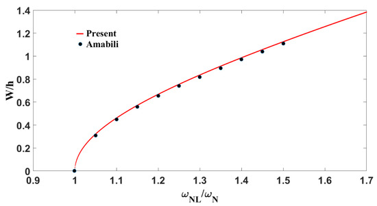
Figure 8.
Backbone for a square, simply supported, immovable aluminum plate .
The next study was conducted on the same immovable aluminum plate previously described, but under a concentrated harmonic force at the center of magnitude and a modal damping ratio of .
The dimensionless transverse displacement is plotted against the normalized excitation frequency . The plot reveals a typical softening-type nonlinear behavior, where the frequency decreases with increasing amplitude, leading to a leftward-bending response curve. As the excitation frequency increases, the system follows a stable upper branch until it reaches a critical turning point, beyond which a sudden jump to a lower amplitude occurs; this is known as the jump-down phenomenon. On the contrary, when the frequency is decreased, the system exhibits a jump-up behavior. This response is a sign of strong geometric nonlinearity and amplitude-dependent stiffness reduction. The moderate damping present smooths the response without eliminating the nonlinear effects. It can be seen in Figure 9 below that the calculated results were in excellent agreement with the ones given by Amabili [38], validating the model’s capability in capturing the complex nonlinear dynamic behavior under forced vibration. Such findings are essential for accurately predicting resonance and ensuring the structural integrity of thin-walled aerospace components subjected to large dynamic loads.
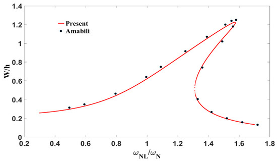
Figure 9.
The frequency–amplitude curve of the nonlinear vibrations of an immovable aluminum plate under F = 1.74 N and ζ = 0.065.
For the case of functionally graded material plates, both quadratic and cubic nonlinear terms exist. Therefore, in order to validate the present formulation, frequency–response curves for nonlinear free and forced vibrations are calculated and compared with previously published works.
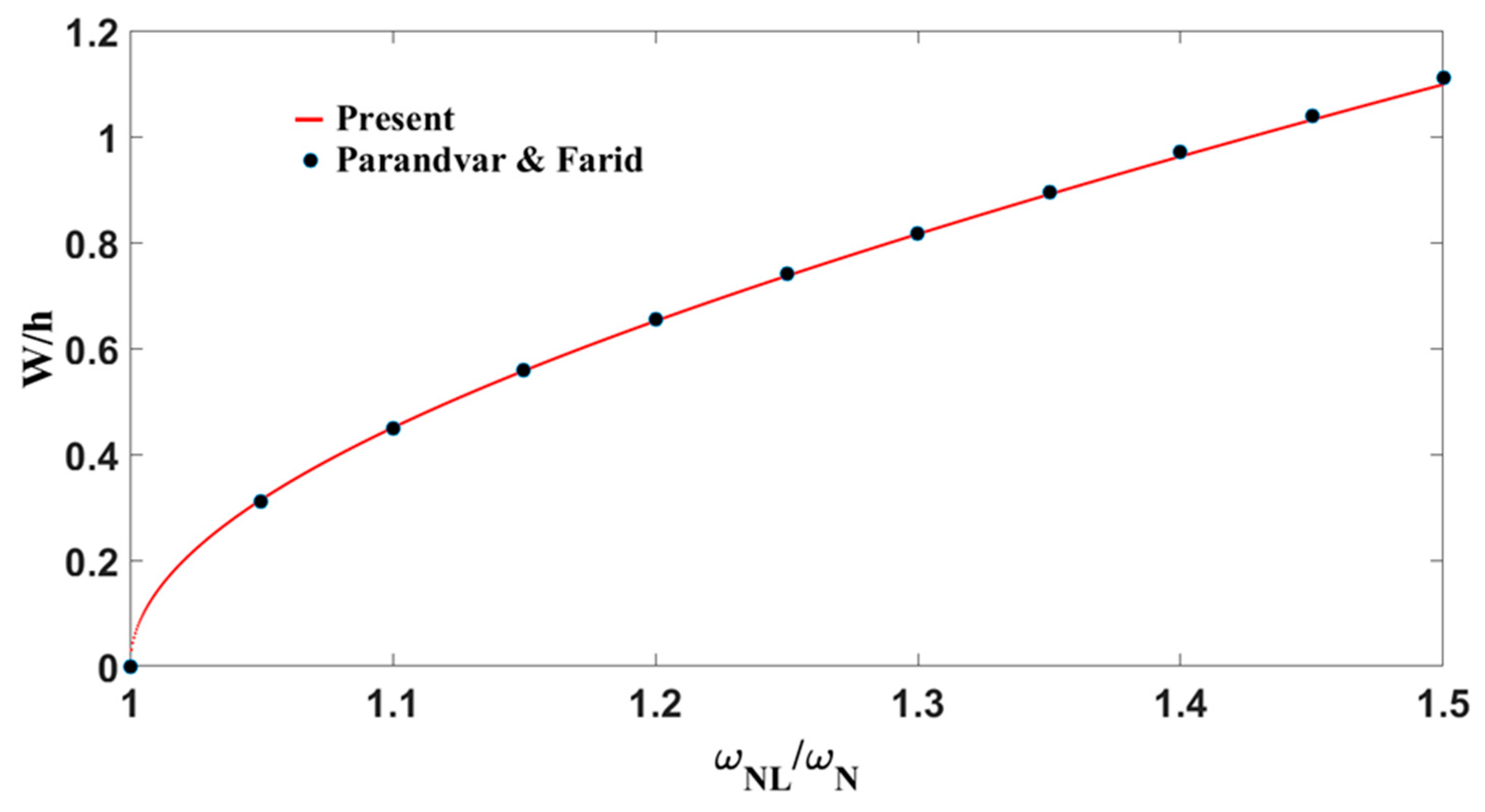
The backbone curve for a simply supported square plate with immovable edges made of was studied. The results obtained here were compared with Parandvar and Farid [37] in Figure 10 bellow and a very good agreement was found.
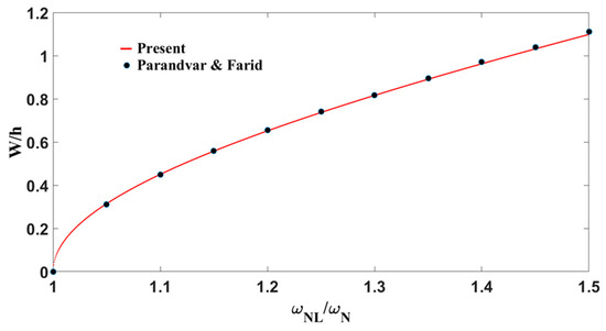
Figure 10.
Backbone curve for a square simply supported immovable plate ( and
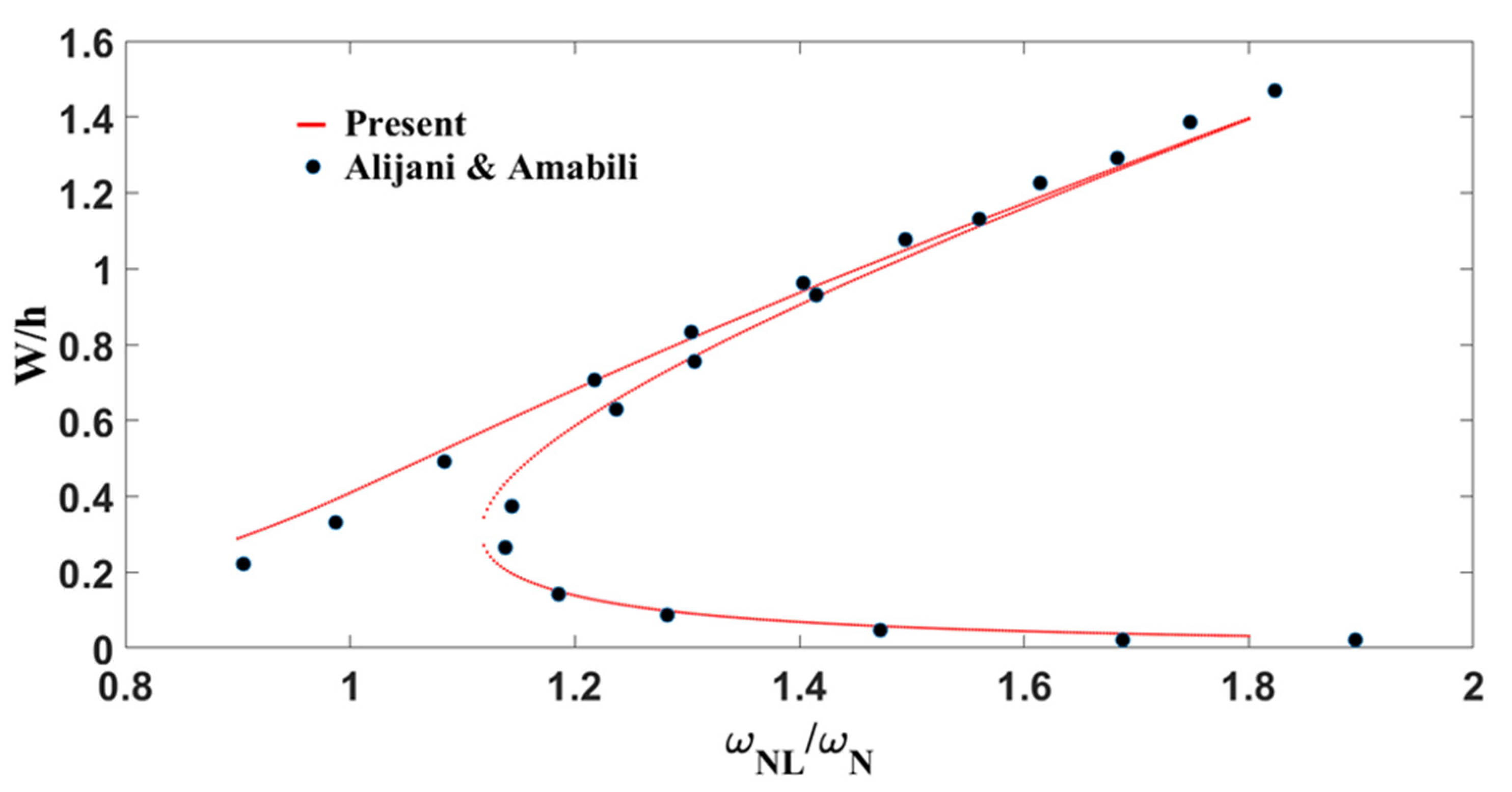
Next, the calculation of the amplitude frequency relationship for the same simply supported immovable FGM plate was carried out and compared to Alijani and Amabili [39]. Figure 11 shows the forced vibration frequency–response plot of . It can be seen that the present results are in good agreement with those of Alijani and Amabili. Similar nonlinear behavior and dynamic phenomena were observed for both the pure metal and the functionally graded material (FGM) cases.
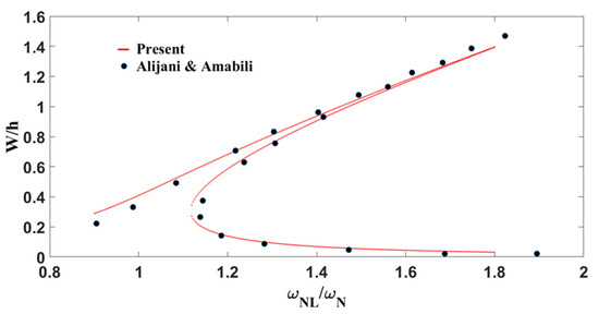
Figure 11.
The frequency–amplitude curve of the nonlinear vibration of an immovable plate (, ) under concentrated and damping
After validating the adopted method, the frequency response of a functionally graded stiffened spherical shell is considered. The structure is made of aluminum (Al) and alumina (.
It can be seen from both plots (Figure 12 and Figure 13), that the frequency–amplitude curves of the forced vibration responses are asymptotic to the free vibration responses. Here both cases display an initial softening behavior followed by hardening. This is due to very high excitation leading to the geometric nonlinearity of the stretching type.
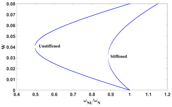
Figure 12.
The frequency–amplitude curve of the free nonlinear vibration of stiffened and unstiffened spherical shells;
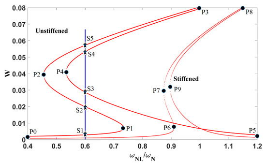
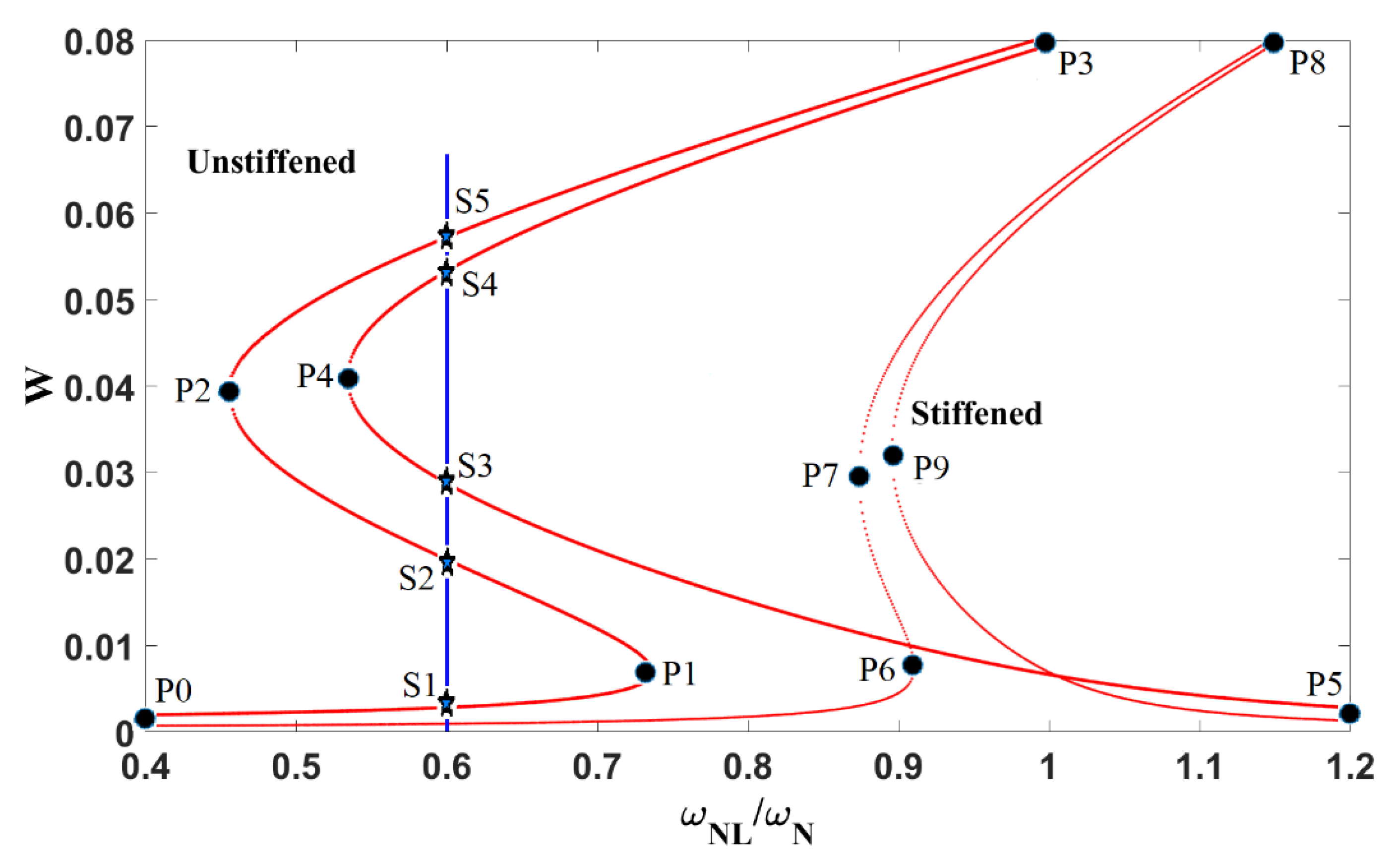
Figure 13.
The frequency–amplitude curve of the forced nonlinear vibration of stiffened and unstiffened spherical shells under a uniformly distributed load
The points at which the motion changes its behavior, from stable to unstable and vice versa, are referred to as “Saddle-node Bifurcations”. P1, P2, P3, and P4 for the unstiffened spherical shell and P6, P7, P8, and P9 for the stiffened one are called bifurcation points. Table 7 shows the change of motion between two consecutive bifurcation points as well as the change of behavior. For the unstiffened curve in Figure 13, one can observe that, at some dimensionless frequency ratios (, five solutions exist theoretically (S1, S2, S3, S4, and S5). However, this is practically not possible.
Table 7.
Practical behavior of the amplitude–frequency curves of the forced nonlinear vibrations of stiffened and unstiffened FGM spherical shells.
Based on the motion behavior in Table 7, solution S2 and S4 belong to two unstable regions; therefore, they are considered unstable points and cannot be achieved practically. It can be seen that the unstable region and the softening behavior of the unstiffened spherical shell are much bigger than in the stiffened one. Hence, the inclusion of stiffeners effectively increases structural stiffness, reduces the amplitude sensitivity to excitation, and suppresses the severity of nonlinear dynamic instabilities. These findings underscore the critical role of stiffening in enhancing the dynamic stability and robustness of thin-walled shell structures under harmonic loading.
6. Conclusions
The primary objective of this study was to develop a closed-form analytical solution for the amplitude–frequency response of an extended Duffing equation incorporating strong quadratic and cubic nonlinearities, using He’s energy balance method. The effect of structural stiffeners was modeled via the Lekhnitsky smeared technique, which efficiently captures their influence across the thickness of the shell, including torsional contributions, an aspect often neglected in prior work. Based on this formulation, the nonlinear static and dynamic responses of imperfect, stiffened, functionally graded double-curved shells were thoroughly analyzed. The theoretical model, built upon the first-order shear deformation theory and von Kármán geometric nonlinearity, was validated against the existing literature and demonstrated excellent agreement, confirming the reliability of the proposed approach. A detailed parametric study showed that increasing the power-law index reduces structural stiffness due to a higher metallic volume fraction. Geometric imperfections were also found to significantly affect load–deflection behavior, especially in shallow and cylindrical panels. The addition of stiffeners effectively suppressed nonlinear vibration amplitudes and enhanced the dynamic stability of spherical shells without notably altering their fundamental frequencies.
Despite its strengths, the current approach has limitations. The use of FSDT, while computationally efficient, may compromise accuracy for thicker shells, a limitation that could be addressed in future work using higher-order shear deformation theories. Moreover, no experimental validation was performed; thus, future studies should include physical testing, such as with 3D-printed FGM models or digital image correlation (DIC) measurements, to directly verify the predictions. Incorporating Airy stress functions is also recommended to simplify the governing equations and reduce computational effort.
Author Contributions
Conceptualization, H.E.; methodology, B.A.; software, B.A.; validation, B.A.; formal analysis, B.A.; investigation, B.A.; resources, H.E. and B.A.; data curation, K.J.; writing—original draft preparation, B.A.; writing—review and editing, H.E. and B.A; visualization, B.A.; supervision, H.E.; project administration, H.E.; All authors have read and agreed to the published version of the manuscript.
Funding
This research received no external funding.
Data Availability Statement
The raw data supporting the conclusions of this article will be made available by the authors on request.
Conflicts of Interest
The authors declare no conflict of interest.
References
- Reddy, J.N. Analysis of Functionally Graded Plates. Int. J. Numer. Meth. Engng. 2000, 47, 663–684. [Google Scholar] [CrossRef]
- Kawasaki, A.; Watanabe, R. Concept and P/M Fabrication of Functionally Gradient Materials. Ceram. Int. 1997, 23, 73–83. [Google Scholar] [CrossRef]
- Hosseini-Hashemi, S.; Rokni Damavandi Taher, H.; Akhavan, H.; Omidi, M. Free Vibration of Functionally Graded Rectangular Plates Using First-Order Shear Deformation Plate Theory. Appl. Math. Model. 2010, 34, 1276–1291. [Google Scholar] [CrossRef]
- Xiang, S.; Kang, G.; Liu, Y. A Nth-Order Shear Deformation Theory for Natural Frequency of the Functionally Graded Plates on Elastic Foundations. Compos. Struct. 2014, 111, 224–231. [Google Scholar] [CrossRef]
- Strozzi, M.; Pellicano, F. Nonlinear Vibrations of Functionally Graded Cylindrical Shells. Thin-Walled Struct. 2013, 67, 63–77. [Google Scholar] [CrossRef]
- Pradhan, S.C.; Loy, C.T.; Lam, K.Y.; Reddy, J.N. Vibration Characteristics of Functionally Graded Cylindrical Shells under Various Boundary Conditions. Appl. Acoust. 2000, 61, 111–129. [Google Scholar] [CrossRef]
- Shah, A.G.; Mahmood, T.; Naeem, M.N. Vibrations of FGM Thin Cylindrical Shells with Exponential Volume Fraction Law. Appl. Math. Mech. Engl. Ed. 2009, 30, 607–615. [Google Scholar] [CrossRef]
- Bich, D.H.; Xuan Nguyen, N. Nonlinear Vibration of Functionally Graded Circular Cylindrical Shells Based on Improved Donnell Equations. J. Sound Vib. 2012, 331, 5488–5501. [Google Scholar] [CrossRef]
- Yang, J.; Shen, H.-S. Free Vibration and Parametric Resonance of Shear Deformable Functionally Graded Cylindrical Panels. J. Sound Vib. 2003, 261, 871–893. [Google Scholar] [CrossRef]
- Patel, B.P.; Gupta, S.S.; Loknath, M.S.; Kadu, C.P. Free Vibration Analysis of Functionally Graded Elliptical Cylindrical Shells Using Higher-Order Theory. Compos. Struct. 2005, 69, 259–270. [Google Scholar] [CrossRef]
- Golpayegani, I.F.; Arani, E.M.; Foroughifar, A.A. Finite Element Vibration Analysis of Variable Thickness Thin Cylindrical FGM Shells under Various Boundary Conditions. Mater. Perform. Charact. 2019, 8, 491–502. [Google Scholar] [CrossRef]
- Alijani, F.; Amabili, M.; Karagiozis, K.; Bakhtiari-Nejad, F. Nonlinear Vibrations of Functionally Graded Doubly Curved Shallow Shells. J. Sound Vib. 2011, 330, 1432–1454. [Google Scholar] [CrossRef]
- Bich, D.H.; Long, V.D. Non-Linear Dynamical Analysis of Imperfect Functionally Graded Material Shallow Shells. Vietnam J. Mech. 2010, 32, 1–14. [Google Scholar] [CrossRef] [PubMed]
- Matsunaga, H. Free Vibration and Stability of Functionally Graded Circular Cylindrical Shells According to a 2D Higher-Order Deformation Theory. Compos. Struct. 2009, 88, 519–531. [Google Scholar] [CrossRef]
- Zannon, M.; Abu-Rqayiq, A.; Al-bdour, A. Free Vibration Frequency of Thick FGM Spherical Shells Based on a Third-Order Shear Deformation Theory. Eur. J. Pure Appl. Math. 2020, 13, 766–778. [Google Scholar] [CrossRef]
- Sayyad, A.S.; Ghugal, Y.M.; Kant, T. Higher-Order Static and Free Vibration Analysis of Doubly-Curved FGM Sandwich Shallow Shells. Forces Mech. 2023, 11, 100194. [Google Scholar] [CrossRef]
- Benounas, S.; Belarbi, M.-O.; Van Vinh, P.; Daikh, A.A.; Fantuzzi, N. Finite Element Model for Free Vibration Analysis of Functionally Graded Doubly Curved Shallow Shells by Using an Improved First-Order Shear Deformation Theory. Structures 2024, 64, 106594. [Google Scholar] [CrossRef]
- Huy Bich, D.; Dinh Duc, N.; Quoc Quan, T. Nonlinear Vibration of Imperfect Eccentrically Stiffened Functionally Graded Double Curved Shallow Shells Resting on Elastic Foundation Using the First Order Shear Deformation Theory. Int. J. Mech. Sci. 2014, 80, 16–28. [Google Scholar] [CrossRef]
- Duc, N.D. Corrigendum to “Nonlinear Dynamic Response of Imperfect Eccentrically Stiffened FGM Double Curved Shallow Shells on Elastic Foundation” [Compos. Struct. 99 (2013) 88–96]. Compos. Struct. 2013, 102, 306–314. [Google Scholar] [CrossRef]
- Bich, D.H.; Dung, D.V.; Nam, V.H. Nonlinear Dynamical Analysis of Eccentrically Stiffened Functionally Graded Cylindrical Panels. Compos. Struct. 2012, 94, 2465–2473. [Google Scholar] [CrossRef]
- Rahimi, G.H.; Ansari, R.; Hemmatnezhad, M. Vibration of Functionally Graded Cylindrical Shells with Ring Support. Sci. Iran. 2011, 18, 1313–1320. [Google Scholar] [CrossRef]
- Duc, N.D.; Thiem, H.T. Dynamic Analysis of Imperfect FGM Circular Cylindrical Shells Reinforced by FGM Stiffener System Using Third Order Shear Deformation Theory in Term of Displacement Components. Lat. Am. J. Solids Struct. 2017, 14, 2534–2570. [Google Scholar] [CrossRef]
- Minh, T.Q.; Nam, V.H.; Duc, V.M.; Hung, V.T.; Ly, L.N.; Phuong, N.T. Nonlinear Vibration and Dynamic Buckling Responses of Stiffened Functionally Graded Graphene-reinforced Cylindrical, Parabolic, and Sinusoid Panels Using the Higher-order Shear Deformation Theory. Z. Angew. Math. Mech. 2024, 104, e202300580. [Google Scholar] [CrossRef]
- Bich, D.H.; Dung, D.V.; Nam, V.H. Nonlinear Dynamic Analysis of Eccentrically Stiffened Imperfect Functionally Graded Doubly Curved Thin Shallow Shells. Compos. Struct. 2013, 96, 384–395. [Google Scholar] [CrossRef]
- Wattanasakulpong, N.; Chaikittiratana, A. An Analytical Investigation on Free Vibration of FGM Doubly Curved Shallow Shells with Stiffeners under Thermal Environment. Aerosp. Sci. Technol. 2015, 40, 181–190. [Google Scholar] [CrossRef]
- Singh, A.K.; Pal, A.; Sahu, A.; Roy, A. Non-Linear Strain Based FE Model for Free Vibration Analysis of Stiffened Functionally Graded Folded Plates in Hygrothermal Environment. Mech. Based Des. Struct. Mach. 2025, 53, 1–31. [Google Scholar] [CrossRef]
- Reddy, J.N.; Chin, C.D. Thermomechanical Analysis of Functionally Graded Cylinders and Plates. J. Therm. Stress. 1998, 21, 593–626. [Google Scholar] [CrossRef]
- Lee, Y.Y.; Zhao, X.; Reddy, J.N. Postbuckling Analysis of Functionally Graded Plates Subject to Compressive and Thermal Loads. Comput. Methods Appl. Mech. Eng. 2010, 199, 1645–1653. [Google Scholar] [CrossRef]
- Brush, D.O.; Almroth, B.O. Buckling of Bars, Plates, and Shells; McGraw-Hill: New York, NY, USA, 1975. [Google Scholar]
- Birman, V. Plate Structures; Springer Science & Business Media: Berlin/Heidelberg, Germany, 2011; Volume 178, ISBN 978-94-007-1714-5. [Google Scholar]
- Chia, C.-Y. Nonlinear Analysis of Plates; McGraw-Hill Inc.: New York, NY, USA, 1980; ISBN 0-07-010746-7. [Google Scholar]
- Kobayashi, Y.; Leissa, A.W. Large Amplitude Free Vibration of Thick Shallow Shells Supported by Shear Diaphragms. Int. J. Non-Linear Mech. 1995, 30, 57–66. [Google Scholar] [CrossRef]
- He, J.-H. Some Asymptotic Methods for Strongly Nonlinear Equations. Int. J. Mod. Phys. B 2006, 20, 1141–1199. [Google Scholar] [CrossRef]
- Quan, T.Q.; Duc, N.D. Nonlinear Vibration and Dynamic Response of Shear Deformable Imperfect Functionally Graded Double-Curved Shallow Shells Resting on Elastic Foundations in Thermal Environments. J. Therm. Stress. 2016, 39, 437–459. [Google Scholar] [CrossRef]
- Chorfi, S.M.; Houmat, A. Non-Linear Free Vibration of a Functionally Graded Doubly-Curved Shallow Shell of Elliptical Plan-Form. Compos. Struct. 2010, 92, 2573–2581. [Google Scholar] [CrossRef]
- Carrera, E.; Brischetto, S.; Cinefra, M.; Soave, M. Effects of Thickness Stretching in Functionally Graded Plates and Shells. Compos. Part B Eng. 2011, 42, 123–133. [Google Scholar] [CrossRef]
- Parandvar, H.; Farid, M. Large Amplitude Vibration of FGM Plates in Thermal Environment Subjected to Simultaneously Static Pressure and Harmonic Force Using Multimodal FEM. Compos. Struct. 2016, 141, 163–171. [Google Scholar] [CrossRef]
- Amabili, M. Nonlinear Vibrations of Rectangular Plates with Different Boundary Conditions: Theory and Experiments. Comput. Struct. 2004, 82, 2587–2605. [Google Scholar] [CrossRef]
- Alijani, F.; Amabili, M. Effect of Thickness Deformation on Large-Amplitude Vibrations of Functionally Graded Rectangular Plates. Compos. Struct. 2014, 113, 89–107. [Google Scholar] [CrossRef]


Disclaimer/Publisher’s Note: The statements, opinions and data contained in all publications are solely those of the individual author(s) and contributor(s) and not of MDPI and/or the editor(s). MDPI and/or the editor(s) disclaim responsibility for any injury to people or property resulting from any ideas, methods, instructions or products referred to in the content. |
© 2025 by the authors. Licensee MDPI, Basel, Switzerland. This article is an open access article distributed under the terms and conditions of the Creative Commons Attribution (CC BY) license (https://creativecommons.org/licenses/by/4.0/).