1. Introduction
The success of the Standard Model (SM) in describing matter and interactions cannot be overstated, but it is not a complete description: it does not explain dark matter and dark energy [
1], it predicts charge-parity (CP) violations in the strong force, which have not yet been observed [
1,
2,
3], and there is no quantized description of gravity [
1]. This incompleteness has lead to many theories to fill the gaps in the SM.
One such approach is hypothesizing an interaction mediated by an as-yet undiscovered boson [
4,
5]. If the hypothetical boson is massive it leads to Yukawa-like interactions [
6], but if it is massless, the interaction will be parameterized with a power law [
7]. This power law is typically written as a correction to Newtonian gravity and for two point masses is expressed as
where
G is Newton’s gravitational constant,
and
are point masses separated by a distance
r,
is the strength of the correction relative to gravity for a particular power of
n, and
is a constant used to preserve the dimension of the interaction; in this work
m. The value of
was chosen to be the same as in Ref. [
8] so that the
reported in this work can be directly compared to the
found in Ref. [
8].
Previous experiments to probe both power law and Yukawa-like deviations in Newtonian gravity were reported in Refs. [
8,
9,
10]. One experiment to probe hypothetical Yukawa-like interactions was carried out in 2016 [
11]. The Yukawa-like interaction of the form
was probed and the experiment placed the best limits on
for a range of
nm, where
is the strength of the correction and
is the Compton wavelength of a massive hypothetical boson [
11]. The experiment consisted of a spherical test mass attached to a micromechanical oscillator that was brought within 200 nm of a source mass made of alternating Au and Si sections, and the force was measured between the two masses. The set-up was not designed to probe power law extensions of the SM and was expected to not be sensitive enough to improve those limits. However, a reanalysis of the force measurements from [
11] and a full analysis with the data was never carried out in the context of a power law.
This work carries out a full analysis considering power law extensions of the SM on the force measurements in [
11] as well as on new data. The limits obtained are not an improvement over the current best limits [
8,
10], so we discuss what would need to be done for the approach in [
11] to improve limits on power law extensions to the SM.
2. Materials and Methods
Ref. [
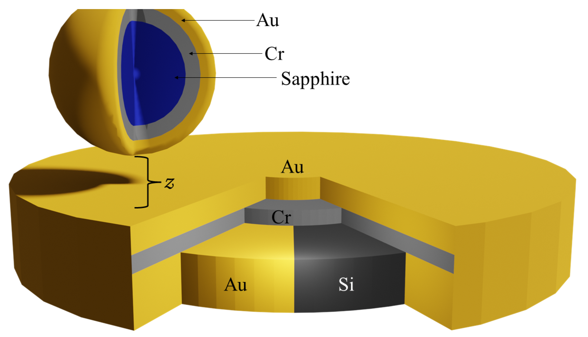
11] used a differential force measurement technique between a spherical test mass attached to a micromechanical oscillator and a source mass. The test mass was a sphere composed of 3 layers; a central sapphire core with a 149.3 ± 0.2
m radius covered by 10 nm of Cr followed by 250 nm of Au (see
Figure 1 for a cross-sectional diagram of the test and source mass). The sphere was glued to a 500 × 500
m micromechanical oscillator and the system had a quality factor Q ∼ 7200. The deflection of the test mass was measured through a change in capacitance between the oscillator’s plate and electrodes located below the plate.
The source mass was a layered structure consisting of BK7 Schott glass followed by a 2.10 ± 0.02
m layer of alternating sections of Au and Si. The Au and Si sectors shared a common layer of a 10 ± 1 nm Cr wetting layer, on top of which was a 150 nm Au layer covering the sample. The shared top Au layer thickness was chosen to be larger than the effective penetration depth of the Casimir force. In this way, the contribution due to the Casimir force is the same whether the test mass is located over a Si sector or an Au sector and leads to a Casimir-less measuring technique as described in [
12].
The test mass was brought to within 200 nm of the source mass’s surface, and at this separation the minimum detectable force is 12 fN/. The closest the masses could be brought is ∼200 nm without the Casimir force making the sphere jump into contact and ruining the whole experiment. The sensitivity also decreases as the separation increases.
The source mass was rotated so that the sections alternated under the test mass at the oscillator’s resonant frequency. Doing so makes the experiment select the first harmonic of the force commensurate with the period of the samples.
While the source masses used to set limits on the Yukawa-like interaction [
11] had upwards of 300 Au and Si sections, there were source masses that had only two, 1 mm wide, sections of alternating gold and silicon, as depicted in
Figure 2. One sample had an inner radius of 2.5 mm and the other had an inner radius of 5 mm. The layered structure is the same as the 300 section samples, except the wetting layer is Ti. The data taken with these larger source masses were not previously analyzed.
To extract limits on
, the force due to the potential expressed in Equation (
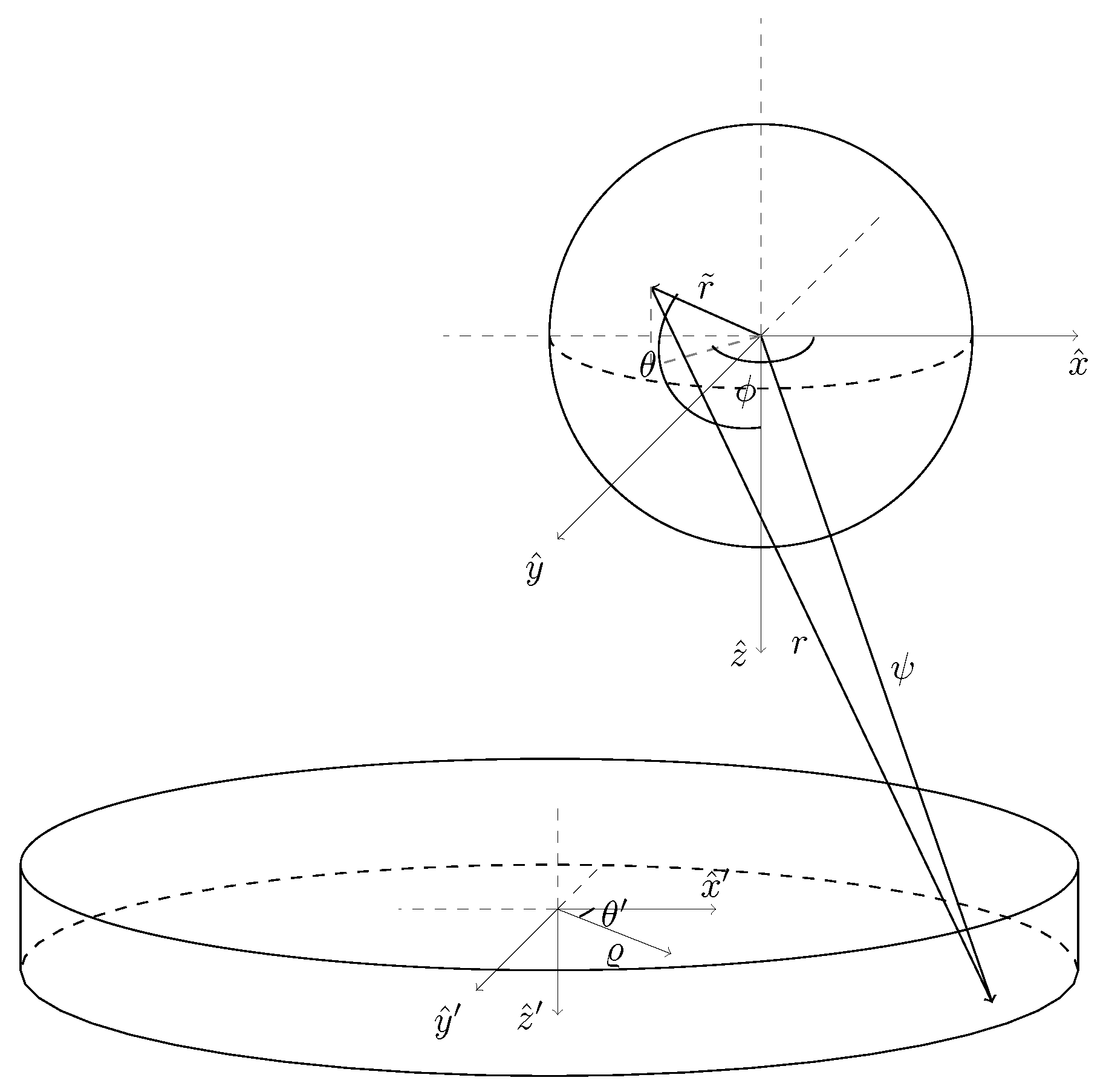
1) was calculated by integrating over the experimental geometry. First, the interaction between a spherical test mass and an arbitrary point in the source mass was calculated analytically with a coordinate system centered at the sphere, shown as the unprimed coordinate system in
Figure 3, using spherical coordinates (
), where
and
are the polar and azimuthal angle, respectively. The potential energy between the sphere and the source mass is
where
R is the radius of the sphere,
and
are the densities of the sphere and the point, respectively,
is the distance from the center of the sphere to the arbitrary point in the source mass, and
is the differential volume of the source mass; see
Appendix A for details. It was verified that Equation (
3) does not diverge for
2, 3, and 4 by taking the limit of Equation (
3) as
2, 3, and 4, respectively. These limits can be seen in
Appendix A. The integrals over the source mass were carried out using cylindrical coordinates (
,
,
) in the primed coordinate system, see
Figure 3, centered in the middle of the source mass. In the primed coordinate system
where
is the radial variable integrated between the inner and outer radius of the sample,
is the angular extent of the sample,
is the radial distance to the sphere,
is the angular position of the sphere,
is the vertical position of the center of the sphere, and
is the vertical coordinate integrated over the thickness of the sample.
The experiment is only sensitive to forces in the vertical direction. Normally, calculating the force in the
z direction would be carried out by
where
is the differential force in the vertical direction that needs to be integrated over the geometry of the source mass. However, since Equation (
5) needs to be integrated along
, calculating the derivative explicitly can be avoided because the operations are the inverse of each other, meaning that the integral of Equation (
5) over the source mass in
z is simply the difference of Equation (
3) evaluated at the
integration limits of the source mass,
and
.
where
is the area element of the source mass that remains to be integrated. A polar coordinate system centered at the center of the sample, the primed coordinate system in
Figure 3, is used for the last two integrals. The area element is expressed as
, where (
,
) are the polar coordinates in the primed system. The integrals over
and
were done numerically with Python code using SciPy version 1.11.4 packages [
13].
In order to obtain the correct interaction from the layered geometry, the numerical integrations were carried out three times, once for each of the three different layers of the test mass. Each test mass layer was considered to be a solid sphere with corresponding radii of
149.30
m,
149.31
m, and
149.56
m for sapphire, Cr, and Au, respectively. As an example, for
n = 3 the integrations for each layer are
Equations (
7)–(
9) are the integrals over the source mass geometry carried out after the limit of Equation (
3) was taken as
3, where
and
are Equation (
4) evaluated at
and
, respectively. The integrals for the other powers were carried out in the same manner. Once the integrals for each test mass layer are carried out, the total force due to the layered structure of the source mass and test mass (
Figure 1) is
where
,
,
, and
are the densities of Au, Cr, sapphire, and Si, respectively,
indicates the total force in the
z-direction for the power
, and the factor out front,
, accounts for the difference when the sphere is over an Au or Si sector in the source mass. Furthermore, since the first two layers are a shared layer of Au and Cr, the contributions of these layers to the interaction are subtracted out.
The total force was calculated with the test mass at different angular positions (
),
Figure 4. The amplitude of the first harmonic for a particular power,
, of the force commensurate with the period,
, of the sectors was equated to the error bars of the force measurements,
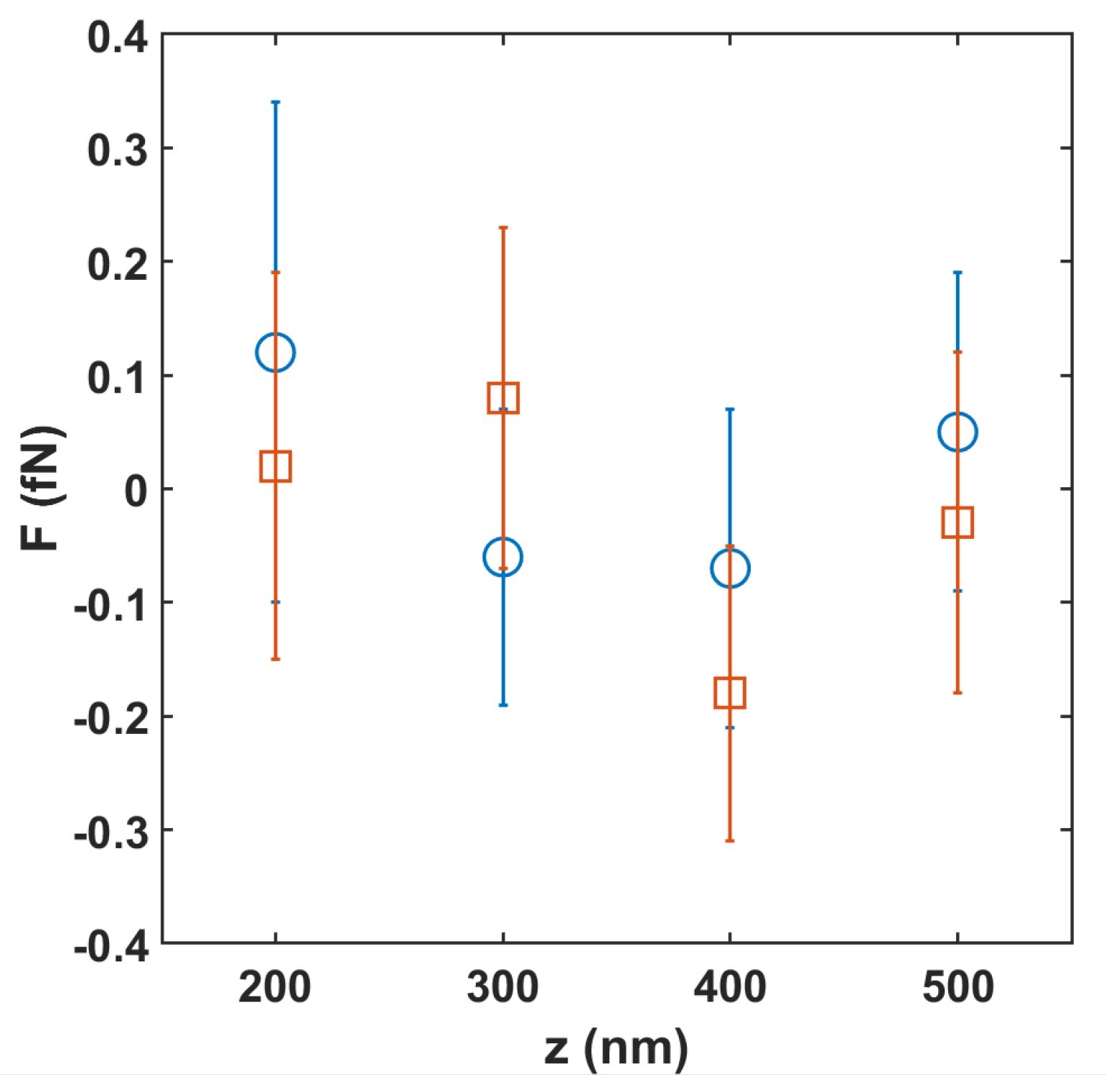
The error bar value is
fN at a separation of 300 nm, as shown in
Figure 5. Equating the calculated first harmonic of the force to the experimental error bar allows limits on
to be extracted,
The same method to determine limits was used for the powers of
1 to 5.
Table 1 shows the limits placed on
from both the 300 sector source masses used in [
11] and the 4 sector source mass with inner radius of 2.5 mm as depicted in
Figure 2.
4. Discussion
While the experiment did not yield better limits on
, changes could be made that would improve the system’s sensitivity. For example, if the source masses were designed with a power law in mind, the limits could be further improved.
Figure 6 shows the potential limits for
as a function of the sample’s radial extent (
) for a thickness of 2 mm. The limits have a similar functional dependence with the other dimensions of the sample as the radius increases. The improvement is attributed to the larger volume of interaction improving the sensitivity of the measurement, yielding better limits. However, the improvement gained in the limits by increasing the source mass’s volume quickly diminishes.
Altering the test mass to also have a larger volume of interaction could provide a small improvement on power law limits. Considering a system, like the one proposed in [
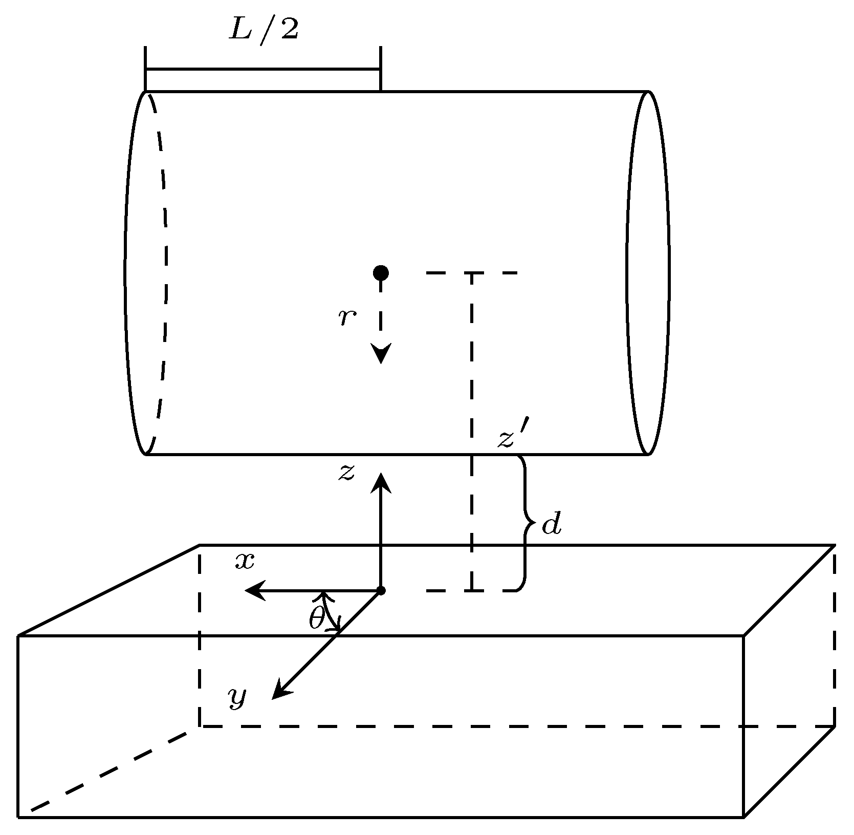
14], where the test mass is cylindrical. If the spherical test mass is exchanged for a cylindrical one, and we carry out a similar analysis ot the one described above, the expected limits using the new test mass can be calculated. The details of the calculation can be found in
Appendix B. The following is the expression of the force between a cylindrical test mass and an infinite slab with thickness
mm along the vertical direction
where
,
, and
m the length of the cylinder. The expected limits for the powers
using a cylindrical test mass are listed in
Table 2, calculated using a separation
nm. Only the power
is expected to improve by about an order of magnitude using a cylinder. Using a cylinder with a length of 500
m and radius of curvature
m optimizes the sensitivity given the constraints of the micromechanical oscillator and the lithographic fabrication method of the cylinder.
Other aspects of the experimental design could be change but would either have little impact or have fabrication limitations. One could conceivably use source mass materials that have larger difference in density since, as seen in Equation (
10), the response is proportional to the difference in densities between the two materials. Changing the source materials, however, will not improve the signal by more than a factor of ∼2 if using Osmium and air. Certainly, our selection of Au and Si is not optimal, but as they are relatively easy to work with, we think it is a convenient selection. In regards to the test mass, Au is again a suitable choice. A thicker layer of Au would benefit the experiment; however, we started to observe a peel off of the Au from the sphere at 300 nm.


