Abstract
Graphene, a two-dimensional material with remarkable electrical, thermal, and mechanical properties, has revolutionized the fields of electronics, energy storage, and nanotechnology. This review presents a comprehensive analysis of graphene synthesis techniques, which can be classified into two primary approaches: top-down and bottom-up. Top-down methods, such as mechanical exfoliation, oxidation-reduction, unzipping carbon nanotubes, and liquid-phase exfoliation, are highlighted for their scalability and cost-effectiveness, albeit with challenges in controlling defects and uniformity. In contrast, bottom-up methods, including chemical vapor deposition (CVD), arc discharge, and epitaxial growth on silicon carbide, offer superior structural control and quality but are often constrained by high costs and limited scalability. The interplay between synthesis parameters, material properties, and application requirements is critically examined to provide insights into optimizing graphene production. This review also emphasizes the growing demand for sustainable and environmentally friendly approaches, aligning with the global push for green nanotechnology. By synthesizing current advancements and identifying critical research gaps, this work offers a roadmap for selecting the most suitable synthesis techniques and fostering innovations in scalable and high-quality graphene production. The findings serve as a valuable resource for researchers and industries aiming to harness graphene’s full potential in diverse technological applications.
1. Introduction
Graphene is a two-dimensional material consisting of a single layer of carbon atoms arranged in a hexagonal lattice pattern [1], as shown in Figure 1. Each carbon atom in graphene binds to its three neighbors through sp2 hybridization, forming a sigma bond (σ) in the field, and the pi bond (π) is delocalized above and below the field [2]. Since it was first successfully isolated by Andre Geim and Konstantin Novoselov in 2004, graphene has garnered widespread attention among scientists due to its remarkable physical properties and potential for diverse applications in various technological fields. This discovery even received international recognition through the award of the Nobel Prize in Physics in 2010 [3].
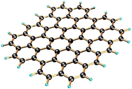
Figure 1.
Graphene Structure Pictures [4].
The advantages of graphene lie in its unique combination of properties, including extremely high electrical and thermal conductivity, outstanding mechanical strength, optical transparency, flexibility, and a large specific surface area [5]. These properties are derived from two-dimensional atomic structures and sp2 bonding systems, which are highly stable and enable the free and efficient movement of electrons in the field. These characteristics make it very promising for application in electronic devices, energy storage, sensors, composite materials, as well as biomedical and environmental technologies [6].
The high prospects of graphene in diverse applications demand efficient and stable synthetic ways to produce quality graphene materials. For its application, graphene has been required to fulfill necessary properties including a well-defined layer number, uniform lateral dimension, low defects, and high purity. These characteristics strongly influence graphene’s performance in its final application since its electrical, mechanical, and chemical properties are very much dependent on its structure and composition [7]. The choice of raw materials is an important consideration to meet the application requirements of graphene specifications. Graphite is the most popular C precursor due to the fact that it can easily be exfoliated into graphene sheets due to its layered structure [8]. The structural transformation from graphite to graphene is illustrated in Figure 2. Moreover, graphite is abundant, relatively inexpensive, and chemically stable, making it an excellent source material for various graphene synthesis methods [9]. In addition to graphite, other low-cost carbon sources, such as biomass, including coconut shells and candlenut shells, have also been explored [10]. However, biomass-derived precursors typically require longer processing times to develop a carbon-like structure and to effectively remove inherent impurities [11].
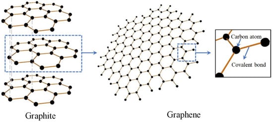
Figure 2.
Graphite to Graphene Schematic Diagram [12].
In addition to the selection of raw materials, the diversity of graphene synthesis approaches that have been developed adds complexity in determining the most effective production strategy. Each of these methods can be used to give a different reaction product, based on reaction conditions, processing stage, and added advanced material. Thus, a comprehensive understanding of these methods is necessary for selecting the one that meets most of the application requirements and research questions [13]. However, despite the availability of various methods, the process of graphene synthesis, in general, still faces major challenges that cannot be considered simple. Regardless of the type of raw material and method used, this process requires highly controlled conditions for a layer of graphene to form without damaging its atomic structure [14]. Errors in process control can result in greater structural defects, changes in particle size, or contamination, which reduces the quality and performance of the resultant graphene [15].
As the synthesis of graphene is increasingly researched and developed, it is necessary to prepare a review that would capture all the approaches that have been undertaken as well as highlight the problems encountered and possible frameworks for further development. The purpose of this article is to provide a comprehensive review of different graphite-based graphene synthesis methods, looking into the main characteristics, concentrating on factors determining the quality of the end product, prospective applications or innovations post-processing, and how these could further advance modern science. In this way, this review will enhance scientific understanding and development of graphene in various technological domains.
2. Graphene Synthesis
The synthesis of graphene is a fundamental stage in the widespread use of this material. Various methods have been developed to obtain graphene from carbon sources, especially graphite, which has a layered structure resembling graphene itself. In the scientific context, these synthesis techniques can generally be classified into two main approaches, namely top-down and bottom-up methods. These two contrasting approaches are illustrated in Figure 3. This classification not only reflects the direction of the synthesis approach but also determines the characteristics of the resulting graphene products [16].
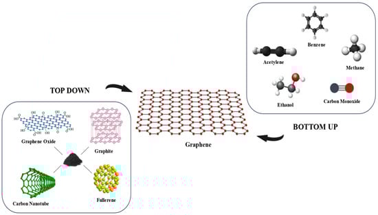
Figure 3.
Precursors for top-down and bottom-up graphene synthesis approaches.
The top-down approach involves separating the graphene layer from the bulk material, such as graphite, fullerene, carbon nanotubes, and graphene oxide through an exfoliation process or chemical reaction, resulting in thin sheets of graphene [17]. Meanwhile, the bottom-up approach forms graphene from simple carbon-based precursors, such as methane, benzene, acetylene, carbon monoxide, and ethanol, through an atomic assembly process via chemical vapor deposition or other synthesis techniques. Top-down methods are generally better suited for large-scale production at lower costs, although control over the number of layers and structural defects is often a challenge [18]. In contrast, the bottom-up method offers better control over the structure of graphene but with greater complexity and process costs [19]. The following is the schematic of the graphene synthesis method, as shown in Figure 4.
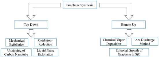
Figure 4.
Top-Down and Bottom-Up Graphene Synthesis Flowchart [20].
Numerous top-down and bottom-up methods for graphene synthesis have been developed. Depending on the advanced treatment and reaction conditions, each method has a different set of working principles, stages, and outcomes. A thorough analysis of these methods is provided in the section that follows, beginning with a top-down strategy and moving on to a bottom-up strategy.
2.1. Top Down
One of the main methods for creating graphene is the top-down approach, which uses physical and chemical procedures to separate the graphene layer from the bulk material, like graphite. Large amounts of graphene are known to be produced using this method, but maintaining product quality is frequently difficult. The following are the top-down graphene synthesis techniques:
2.1.1. Mechanical Exfoliation
Mechanical exfoliation is a top-down method of producing graphene, where layers of graphite are separated using mechanical forces, such as normal or shear forces, to overcome the van der Waals tensile forces between layers. This method avoids major chemical reactions and is comparatively easy and economical by using mechanical energy to exfoliate graphite into single-layer or multilayer graphene [21]. There are several physical methods for performing mechanical exfoliation, and each has unique properties. These are a few methods that are frequently employed in this approach.
Micromechanical Cleavage
Micromechanical cleavage is an exfoliation technique that utilizes the adhesion force of an adhesive (e.g., tape) to physically exfoliate the graphene layer. Geim and Novoselov first introduced this technique, and it was later refined using polymers such as PMMA and PDMS [22]. The use of PMMA is more effective in producing monolayer graphene, while PDMS tends to produce multilayers. This suggests that PMMA is better suited for producing high-quality graphene with a thickness of one [23].
In addition to the exfoliation method using adhesives, a new technique has been developed based on a single diamond tip that is very sharp. This method utilizes a single, very sharp diamond tip for precise exfoliation down to the atomic scale. This approach is capable of producing high-quality multilayer graphene with a thickness of tens of nanometers and a lateral size of about 900 × 300 μm. The use of ultrasonic vibrations (33.1 kHz, 2.1 V) was shown to be able to lower the ID/IG ratio from ~0.90 to ~0.73 and the crystallite size from ~24 nm to ~17 nm, indicating an improvement in the quality and stability of the MLG. TEM analysis showed a more organized structure as well as the emergence of nanohorns, which have the potential for gas storage applications [24].
Sonication
Sonication is a commonly used auxiliary technique in the graphene synthesis method that utilizes high-frequency ultrasonic waves to generate mechanical energy through the phenomenon of cavitation. Ultrasonic waves create microscopic bubbles that collapse rapidly, resulting in intense shear forces that can overcome the Van der Waals forces between graphite layers. As a result, sonication facilitates the exfoliation of graphite into graphene, often in liquid-phase systems, rather than serving as a standalone synthesis method. This process can be conducted without the need for aggressive chemical reagents [25].
The effectiveness of sonication techniques in graphene synthesis is highly dependent on the duration, sonication power, solvent type, and initial treatment of graphite materials. Sonication not only facilitates mechanical exfoliation but can also cause structural defects in graphene sheets, depending on process conditions. Therefore, characterization analysis, such as FTIR, SEM, Raman, and XRD, is important to evaluate the exfoliation outcomes, ranging from the presence of functional groups and morphology to the degree of defects and crystallinity of graphene [26]. The following is a summary of the characterization data, as presented in Table 1.

Table 1.
Summary of characterization data assisted by sonication techniques.
Sonication effectively exfoliates graphite into graphene, as evidenced by an increase in the ID/IG ratio (Raman), a flaky sheet morphology (SEM), and an angular shift of 2θ (XRD), indicating an increase in interlayer spacing. Changes in the intensity of functional groups in FTIR also indicate surface chemical modifications. Overall, sonication is a simple and effective support technique that requires optimization to produce high-quality graphene with minimal defects.
Ball Milling
Ball milling is an auxiliary mechanical technique used within top-down approaches for graphene production, involving the grinding of graphite using steel or ceramic balls in a rotating container. The mechanical impact and shear forces generated during this process facilitate the exfoliation of graphite layers into thinner sheets. Although not strictly considered a synthesis method, ball milling is known for its simplicity, low cost, and suitability for large-scale graphene preparation.
There are two methods for the ball mill technique: wet methods and dry methods. The dry method is a simpler procedure because it does not require solvents. In contrast, the wet method uses solvents like ethanol or water to help create graphene suspensions, lower frictional heat, and speed up the graphite peeling process. However, it requires additional steps for the separation and drying of the final product [32]. The following are the differences in the characteristics of graphene from dry and wet ball milling, as shown in Table 2.
Table 2.
Summary of characterization data assisted by wet and dry ball milling techniques.
The wet and dry ball-mill methods both produce thinly coated graphene/GO with increased defects and decreased crystallinity. The wet method results in a more homogeneous structure and higher quality, suitable for electronics, sensors, and energy. The dry method produces graphene with higher oxygen functionalities, suitable for adsorption, catalysts, and composites, and is simpler, cheaper, and more environmentally friendly for large-scale production [43].
Fluid Dynamics
Fluid dynamics is an auxiliary technique used in top-down approaches for graphene production, utilizing the movement of fluids and their interactions with solid surfaces. In graphene synthesis, this principle is used to exfoliate graphite into a thin layer of graphene without the use of harmful chemicals. This process relies on a high-speed flow of fluid that generates mechanical forces, such as friction, turbulence, cavitation, and differential pressure, to overcome the van der Waals forces between graphite layers. This technique is considered efficient and environmentally friendly, and has the potential to be developed on an industrial scale [44].
The three primary fluid dynamics-assisted exfoliation techniques are the Vortex Fluidic Device (VFD), Pressure-driven Fluid Dynamics (PFD), and Mixer-driven Fluid Dynamics (MFD). VFD utilizes a fast-rotating tube to produce a thin layer of fluid and applies a gentle shear force to exfoliate graphite. PFD involves the flow of graphite suspension through a narrow channel under high pressure, triggering exfoliation through a combination of shear forces, turbulence, and cavitation. Meanwhile, MFDs utilize mixing tools such as rotor-stator mixers or blenders to produce high shear forces evenly, suitable for efficient large-scale graphene production [45]. The following table summarizes the graphene characterization data generated by the three techniques, as shown in Table 3.
Table 3.
Summary of characterization data assisted by fluid dynamics-based exfoliation techniques.
Fluid dynamics techniques offer a promising, greener alternative to chemical methods for graphene production. VFD is effective for producing graphene with minimal defects, but its throughput is limited. PFD enables size control and high efficiency, although it requires high pressure and complex equipment. MFD provides a cost-effective and practical solution for large-scale graphene processing. With ongoing technological advancements, fluid dynamics-assisted approaches represent a strong potential route for sustainable and commercial-scale graphene production.
Supercritical Fluids
A supercritical fluid is a substance that exists at temperatures and pressures above its critical point, where the boundary between the liquid and gaseous phases is lost. Under these conditions, the fluid has liquid-like properties with high density while also having high diffusivity, like gases. This combination of properties allows supercritical fluids to penetrate the interlayer gaps of graphite and facilitate exfoliation without the need for harsh chemicals. In addition, when the pressure is lowered, the rapid expansion of the fluid results in an effective separating force between graphite layers [46].
In graphene synthesis, supercritical fluids can be divided into two main types: inert and reactive. Inert fluids such as CO2 do not react chemically with graphene, making them suitable for producing pure graphene. In contrast, reactive fluids such as supercritical ethanol not only aid in exfoliation but can also modify the surface of graphene through chemical reactions. The selection of this type of fluid is adjusted to the needs of the desired graphene end application [47]. The following table lists the differences in graphene characteristics generated through the two supercritical fluid approaches, as shown in Table 4.
Table 4.
Summary of characterization data produced by supercritical fluid methods.
Exfoliation of graphene with pure SC-CO2 tends to result in less homogeneous structures and a higher number of defects. In contrast, the use of SC-ethanol is more effective in producing graphene with a more stable thickness distribution, a more regular structure, and a lower defect rate. Thus, SC-ethanol is superior for the synthesis of high-quality graphene.
Detonation Technique
The detonation technique is a graphene synthesis method that utilizes the explosive reaction of carbon compounds, such as acetylene, in the presence of oxygen or oxidizing agents to produce graphene nanosheets. The high temperatures and pressures created during the detonation process break down carbon molecules and facilitate the formation of graphene structures [52]. This method is very fast, does not require a catalyst, and is capable of producing high-quality graphene efficiently, making it suitable for large-scale production. The following table summarizes the graphene characterization data generated by this method, as shown in Table 5.
Table 5.
Summary of characterization data produced by detonation methods.
The detonation technique is capable of producing high-quality graphene with a good crystalline structure, minimal defects (low ID/IG), and a varying number of layers. This process is fast, catalyst-free, and suitable for large-scale production, making it an efficient and promising method for graphene synthesis.
2.2. Oxidation-Reduction
The oxidation-reduction method is a graphene synthesis technique that involves oxidizing graphite to produce graphene oxide (GO), followed by exfoliation and chemical reduction to form reduced graphene oxide (rGO) [57]. This process begins with the oxidation of graphite using strong oxidizers, such as sulfuric acid, nitric acid, or potassium permanganate, which introduces oxygen functional groups, including hydroxyl, epoxy, and carboxyl, into the graphite layer [58]. This function group increases the distance between layers, allowing exfoliation into GO sheets through sonication in solvents such as water [59]. The resulting GO is hydrophilic and easily dispersed; however, it lacks the conductive properties of graphene due to the disruption of the sp2 structure caused by oxidation [60].
The reduction stage is performed to remove the oxygen group and restore the sp2 carbon structure, using reducing agents such as hydrazine, sodium borohydride, or thermal methods to produce reduced graphene oxide (rGO) [61]. Although this method enables the production of large quantities of graphene at a low cost, rGO often exhibits structural defects and oxygen group residues that degrade its electronic properties compared to pure graphene [62]. The quality of graphene can be improved by optimizing the reduction conditions, such as using environmentally friendly reducing agents or electrochemical reduction methods [63]. The oxidation-reduction method is very popular due to its scalability and ease of process; however, the main challenge is minimizing defects for applications that require high-quality graphene [64].
The different processes for oxidizing and reducing graphene will be covered in this section, along with how they affect the final product’s quality and characteristics. The primary focus is on how these techniques affect graphene’s conductivity, defects, and structure for the best possible applications.
2.2.1. Oxidation Method
The properties and applications of graphene can be greatly impacted by the classification of oxidation methods used in graphene synthesis, such as chemical, thermal, and electrochemical oxidation. It is essential to comprehend this method in order to optimize graphene for a variety of applications.
2.2.2. Chemical Oxidation
Chemical oxidation is the initial stage in the synthesis of rGO, where graphite is converted to graphene oxide (GO) using a strong oxidizing agent in an acidic solution. The most common method is the Hummers’ method or its modification, which uses a combination of potassium permanganate (KMnO4) and sulfuric acid (H2SO4), often with the addition of sodium nitrate (NaNO3) [65]. In some variations of these methods, oxidizing agents such as nitric acid (HNO3), peroxide (H2O2), or a mixture of phosphoric acid (H3PO4) and potassium permanganate (KMnO4) are also used [66]. This reaction introduces various oxygen groups such as hydroxyl, epoxy, and carboxyl into the graphite structure, making GO water-soluble and ready for the reduction process to rGO [67].
Thermal Oxidation
In order to introduce oxygen groups at high temperatures, thermal oxidation entails heating graphite with oxygen or other oxidizing gases. To increase the effectiveness of functional group recognition, this technique is frequently used in conjunction with chemical oxidation [68]. Compared to chemical oxidation, thermal oxidation produces graphene with fewer defects because it allows for controlled oxidation at high temperatures. In addition, this method is often used in conjunction with chemical reduction to produce rGO that has better conductivity [69].
Electrochemical Oxidation
This method utilizes an electric current to oxidize graphite in an electrolyte solution, which can be a neutral salt solution, such as sodium sulfate (Na2SO4), or an environmentally friendly electrolyte solution that is less harsh than a strong chemical agent [70]. This process avoids the use of harmful chemical oxidizers such as KMnO4 and strong acids, making it safer and more environmentally friendly [71].
Reduction Method
The following is the reduction of graphene oxide (GO): the structure and electrochemistry of rGO are impacted by techniques like chemical, thermal, and electrochemical treatments, which in turn affect the properties and uses of materials.
Chemical Reduction
The cost-effectiveness and scalability of chemical reduction make it a popular choice. In order to eliminate the oxygen groups from graphene oxide (GO) and partially restore the graphitic structure, reducing agents such as sodium borohydride, hydrazine, metals, L-ascorbic acid, and urea are used in this process. Reduction capacity, toxicity, and environmental impact can all be impacted by changing the choice of reducing agents [72].
Thermal Reduction
Thermal reduction is achieved by heating graphene oxide (GO) in an inert atmosphere, such as argon or nitrogen, to remove oxygen groups as gases (e.g., CO and CO2) [73]. This method does not require any additional chemicals and can produce rGO with high conductivity. However, the process requires good temperature control to prevent damage to the carbon structure [74].
Electrochemical Reduction
Electrochemical reduction involves the use of an electric current to reduce graphene oxide (GO) inside an electrochemical cell [75]. GO is used as an electrode, and when it is given a negative voltage, the oxygen groups on its surface are removed through electron transfer. This method is fast and clean and allows for good control over the reduction results, making it widely considered for sustainable applications [76]. The following table summarizes the graphene characterization data obtained via the oxidation-reduction method, as shown in Table 6.
Table 6.
Summary of characterization data produced by oxidation-reduction methods.
The synthesis of rGO begins with the oxidation of graphite using thermal, chemical (Hummers), or electrochemical methods to introduce oxygen groups that facilitate exfoliation. Furthermore, reductions are carried out chemically (using NaBH4, hydrazine, or ascorbic acid), thermally, or electrochemically to remove these oxygen groups, improve the sp2 structure, and decrease the defects, which is reflected in the decrease in the Raman ID/IG ratio and changes in the XRD pattern.
2.2.3. Unzipping of Carbon Nanotube
The unzipping of carbon nanotubes (CNT) is a top-down method for the synthesis of graphene, specifically graphene nanoribbons (GNR), by splitting the cylindrical structure of the CNT into flat graphene tapes [85]. This process utilizes a CNT wall composed of rolled graphene sheets, resulting in GNR with a width and length that depend on the dimensions of the CNT [86]. While effective for producing graphene with controlled edges, this method can cause structural damage [87]. Various methods, as follows, can unzip carbon nanotubes (CNT) into graphene nanoribbons (GNR):
Oxidative Zipper Retraction
This method utilizes strong oxidizers to break the carbon bonds in carbon nanotubes (CNTs), resulting in graphene nanoribbons (GNRs). This process is general and flexible, allowing the regulation of GNR properties through oxidation rates [88]. Nonetheless, harsh chemical conditions often damage the structure of CNT crystals and degrade their conductivity [89].
Catalytic Zipper Opening
This technique uses microwaves and metal nanoparticles, like palladium, to efficiently accelerate the unzipping of carbon nanotubes. Although layered GNR can be produced using this process, the primary obstacles are the possibility of metal contamination and the requirement for stringent reaction control [90].
Electrochemical Zipper Opening
The CNT zipper can be opened with a high degree of precision and little damage thanks to this method, which uses an electric field in the electrolyte medium. Although it necessitates specialized equipment and rigorous electrochemical condition control, this method works well for nitrogen-doped CNTs [91].
Sonochemical Zipper Opening
This process utilizes ultrasonic waves to open the CNT mechanically. This method is relatively inexpensive and simple, and can produce GNR with smooth edges. However, the quality of the final product may vary due to limited control over the process.
A comparison of the characteristics of graphene nanoribbon (GNR) generated through various carbon nanotube (CNT) unzipping methods is presented in the following table to highlight the advantages and limitations of each approach, as shown in Table 7.
Table 7.
Summary of characteristics of GNR against various methods for unzipping CNT.
Each CNT unzipping method produces a GNR with its advantages and limitations. The oxidative method is easy to do but poses many defects. Catalytic and electrochemical methods produce purer GNR with a more intact structure, although the process is more complex. Sonochemistry is relatively simple, yielding smooth-edged results, but it is not easy to control. The selection of methods depends on the target application and practical considerations such as purity, efficiency, and environmental impact.
2.2.4. Liquid-Phase Exfoliation
Liquid-phase exfoliation (LPE) is a top-down method of graphene synthesis that utilizes solvents or chemicals to separate the graphene layers from the graphite. Unlike mechanical exfoliation, which is physical in nature, this method utilizes chemical interactions or reactions to weaken the forces between layers [96]. Some of the techniques included in chemical exfoliation include:
Graphite Intercalation Compounds (GIC)
GIC is a compound that results from the insertion of chemicals (such as metals or acid molecules) into a graphite layer to widen the distance between layers to facilitate the process of exfoliating graphene through heating or ultrasonication [97]. Intercalation with alkali metals, such as potassium, can increase the distance between graphite layers from 0.34 nm to approximately 0.53 nm. This increase weakens the interlayer van der Waals force, making it easier to exfoliate into graphene [98].
Intercalation with acid molecules, such as HClO4, can produce graphene with high exfoliation efficiency. This intercalation widens the distance between graphite layers, as evidenced by the XRD peak at 2θ = 23.1°. After sonication, the separate layers reform into graphene. The Raman spectrum showed an increase in the peaks of D and G, signaling an increase in disorder and successful exfoliation [99].
Chemical Exfoliation with Organic Solvents
Chemical exfoliation with organic solvents is a method of separating the graphene layer from graphite by utilizing a solvent with a surface tension close to that of graphene (30–40 mJ/m2) [98]. Solvents such as N-methyl-2-pyrrolidone (NMP), dimethylformamide (DMF), and dimethyl sulfoxide (DMSO) are commonly used because they are able to stabilize graphene in suspension and improve exfoliation efficiency [100].
Method Chemical Exfoliation with pure organic solvents produces low-concentration graphene (<0.1 mg/mL). The addition of organic salts such as sodium citrate, sodium tartrate, potassium sodium tartrate, and EDTA disodium has been shown to significantly improve exfoliation efficiency, resulting in high-quality graphene (1–3 layers, oxide-free, and defective) with concentrations of up to ~1 mg/mL in 2 h of sonication [101].
Chemical Exfoliation with Ionic Liquid Exfoliation
Liquid-phase exfoliation with ionic liquid is an environmentally friendly top-down method to produce graphene from graphite. The ionic liquid acts as a stable solvent with a corresponding surface tension, thus allowing the separation of the graphene layer without damaging its structure [102], as shown in Table 8.
Table 8.
Summary of ionic liquid type against characteristic graphene via LPE.
[Ntf2]-based ionic liquids, specifically [C4C1im][Ntf2] and [Pyrr4,1][Ntf2], produce graphene with high concentrations, ≤5 layer counts, and the best purity. In contrast, ionic liquids with other anions, such as [C(CN)3] and [Otf], show low efficiency and high oxidation rates, signaling the crucial role of ionic structures in exfoliation quality. Ionic liquids have been shown to produce high-concentration graphene dispersions without chemical modifications, but their use is still limited due to their high price and high viscosity, which affect the efficiency of exfoliation [103].
Chemical Exfoliation with Surfactants
Liquid exfoliation with surfactants is a method to separate graphite into graphene sheets in solution using ultrasonication, where surfactants function to stabilize graphene sheets so that they do not clump together. This method is effective, simple, and suitable for large-scale graphene production [104], as shown in Table 9.
Table 9.
Summary of Surfactants on Characteristics of Graphene via LPE.
From Table 9, of the six types of surfaces studied, exfoliation with Triton X-100 resulted in the highest concentration of graphene (~0.29 mg/mL) in (~1 mg/mL) surfactant. TEM and AFM show thin sheets with a thickness of 1–3 nm and <5 layers. The average flake size of 46.83 μm2 obtained from SDOC samples indicates a complete and quality graphene morphology. Raman and XPS in the Triton X-100 sample showed low defects and dominance of sp2 structures. The best dispersion stability is also demonstrated by Triton X-100 and Tween 80, with more than 80% of the graphene remaining dispersed after 700 h [105].
Exfoliation with Low-Boiling-Point Solvent
Exfoliation with a low-boiling-point solvent is a method of separating a layer of graphite into graphene using a volatile solvent. High-boiling-point solvents were previously widely used because they were effective, but they were difficult to vaporize and could cause clumping during drying. The use of low-boiling-point solvents is a solution to overcome this problem [106], as shown in Table 10.
Table 10.
Summary of Solvent type against effectiveness via LPE.
Exfoliation with volatile solvents yields good-quality graphene, with a thickness of <5 layers and a low defect rate based on TEM and Raman analyses. Solvents such as isopropanol and chloroform are not only easy to evaporate but are also able to maintain the stability of graphene dispersion. In contrast, high-boiling-point solvents produce higher concentrations, but they tend to cause aggregation during drying, which can degrade the quality of graphene [107].
Exfoliation with Electrochemistry
Electrochemical exfoliation is a fast and environmentally friendly method of producing graphene oxide from graphite using an electric current in an electrolyte solution. This process does not require strong oxidizers, is suitable for large-scale production, and is capable of producing < 10-layer nanosheets with a lateral size of >1 μm [108].
The shape of graphite has a significant effect on the results of electrochemical exfoliation. Compressed graphite powder produces graphene with a lateral size of >30 μm and a yield of 65% [109]. Natural powder produces GO with an oxygen content of 25.3 at.%, an ID/IG ratio of 0.85, and ±9 layers [110]. Graphite foil produces ~1.0 nm thick GO, consisting of 1–3 layers, with a yield of up to 96%, while rods break easily and flake exfoliate quickly but with a lower yield (<40%) [111].
In addition, the type of electrolyte also determines the quality of the graphene formed. H2SO4 (0.5 M) electrolytes produce an ID/IG of 0.35 with rapid blistering, Li2SO4 (0.5 M) produces an ID/IG of 0.25 with moderate exfoliation, and NaClO4 (1 M) produces an ID/IG of 0.17 with non-destructive intercalation [112]. Electrolytes such as HClO4 and HNO3 form epoxy and alkoxy groups, and (NH4)2SO4 allows doping of N and S, while ozone produces 1–3 layers of GO with 16.37 at.% oxygen and 1.21 ID/IG [113]. This data confirms that the combination of graphite shape and the right type of electrolyte greatly determines the quality and efficiency of GO production.
2.3. Bottom-Up
The bottom-up approach is a graphene synthesis strategy that is carried out by gradually forming the structure of graphene from small molecular units such as carbon atoms, usually through chemical processes or deposition. This method generally produces high-quality graphene with a good level of structural control, although scalability and production costs are major challenges. The following techniques are used in the synthesis of graphene by the bottom-up method:
2.3.1. Chemical Vapor Deposition (CVD)
Chemical vapor deposition (CVD) is a vacuum deposition method to produce high-quality graphene through the chemical reaction of a gas precursor on a hot substrate, such as copper or nickel [114]. This process produces the carbon atoms that make up graphene by breaking down gases like methane [115]. For electronics and sensor applications, CVD makes it possible to create graphene with a large surface area and a consistent crystal structure [116]. To reduce flaws in the graphene layer, this procedure necessitates rigorous regulation of temperature, pressure, and gas flow [117].
Temperature
The temperature of synthesis has a major impact on the quality of graphene generated using the CVD process. The number of layers, purity, degree of defects, and interaction with the substrate are all influenced by temperature. High-quality graphene is characterized by uniform coatings, slight defects, high purity, and good substrate interactions, all depending on temperature settings during the process [118]. The following sections discuss the impact of various low, high, and ultra-high temperature ranges on these aspects, as shown in Table 11.
Table 11.
Summary of temperature reactor conditions against graphene characterization via CVD.
By increasing layer uniformity, decreasing defects, and enhancing substrate interactions, high temperatures enhance graphene quality; however, they can also increase energy consumption and cause substrate damage. Although they use less energy, low temperatures can cause quality degradation. For some applications, extremely high temperatures are advantageous, but they must be carefully managed to avoid aggravating flaws or damaging the substrate. These factors must be balanced in order to optimize the CVD process and produce graphene of the appropriate quality.
Pressure
The quality of graphene produced by CVD is greatly influenced by process pressures, whether atmospheric, low, or ultra-vacuum. This pressure affects the number of layers, defects, purity, and interaction with the substrate, with each condition offering its own advantages and challenges [122], as shown in Table 12.
Table 12.
Summary of Pressure reactor conditions against graphene characterization via CVD.
CVD pressure influences graphene growth by altering the viscous boundary layer, which affects the diffusion of active carbon species such as CHₓ radicals to the substrate. Higher pressures thicken this layer, limiting diffusion and reducing nucleation, while lower pressures enhance precursor transport and uniformity [126]. Thus, ultra-high vacuum favors high-purity synthesis, whereas APCVD offers scalability. However, graphene quality also depends on substrate and precursor [127].
Wall
The quality of graphene synthesized with CVD is affected by the configuration of the walls/substrates, both cold walls and hot walls [128]. Here are the differences in graphene results obtained from cold-wall and hot-wall configurations in the CVD method, as shown in Table 13.
Table 13.
Summary of cold-wall and hot-wall configurations against graphene characterization via CVD.
Although the key differences are outlined above, the choice between cold-wall and hot-wall CVD ultimately depends on the target application. Cold-wall systems are gaining interest in industrial settings due to their fast thermal response, while hot-wall systems remain a benchmark for high-quality graphene. Continued optimization of both methods is crucial to balancing performance and scalability.
Deposition Time
Growth rate and deposition time in CVD significantly influence graphene quality. Recent strategies, such as chemically assisted and site-specific growth, enable faster deposition by enhancing precursor dissociation or guiding localized growth, respectively. A comparison with conventional CVD is shown in Table 14.
Table 14.
Comparison of Growth Mechanisms and Graphene Quality between Conventional and Accelerated CVD Strategies.
These advanced strategies not only shorten the deposition time but also provide greater control over domain size, growth location, and material quality, offering significant advantages for scalable and application-specific graphene production.
Gas Flow State
The quality of graphene produced through CVD is affected by the gas flow method, which is an open and closed CVD system. Open systems use a continuous flow of gases, while closed systems maintain a static gas environment. These two methods affect the number of layers, the defect density, and the purity of graphene in different ways, as shown in Table 15.
Table 15.
Summary of gas flow configurations against graphene characterization via CVD.
The choice between open and closed CVD systems depends on the specific quality needs of the graphene application. Open systems are better suited for large-scale production with less uniformity and fewer defects, while closed systems offer better control over the purity and thickness of the coating, ideal for applications that require high quality.
Activated Manner
The synthesis of graphene by various CVD methods, such as thermal, plasma, and laser, has a major effect on the number of layers, defect density, and purity. Each method has advantages and disadvantages that affect the final quality of graphene [136], as shown in Table 16.
Table 16.
Comparison of traditional and emerging CVD techniques for graphene synthesis.
Graphene growth in conventional CVD relies on thermal decomposition and surface diffusion, yielding uniform layers. In PECVD, plasma-induced ion bombardment and localized energy input accelerate nucleation but increase defects and vertical growth. Laser-CVD uses focused heating for patterned growth, while TCVD enhances efficiency through controlled thermal conditions.
2.3.2. Arc Discharge Method
The arc discharge method is a bottom-up graphene synthesis technique that uses the discharge of electricity between graphite electrodes in a gaseous environment to form a carbon plasma, which condenses into graphene, usually few-layer graphene (FLG). High-quality graphene with a good crystalline structure is produced by this process, which vaporizes carbon atoms from graphite at high temperatures, followed by atomic reassembly into graphene sheets. To guarantee homogeneity and purity, however, exact control of variables like gas pressure and current is necessary [141]. Large-scale production is possible with this straightforward process, but minimizing contamination and flaws is a challenge [142]. According to the research that has been done, the following factors influence the quality of graphene using the arc discharge method:
Effect of Buffer Gas Type
Table 17 summarizes how the type of buffer gas greatly affects the properties and quality of graphene produced by arc discharge.
Table 17.
Summary of the effect of gas type on the quality of graphene via arc discharge methods.
By using various gases, the arc release method creates graphene with unique properties: argon for high-quality multilayers, hydrogen for pure graphene with little contamination, nitrogen-hydrogen mixtures for scalability and quality balance, and helium for monolayers. The particular requirements of the application are taken into consideration when choosing the gases.
Effect of Current Type
The structure, purity, and general quality of the synthesized graphene are greatly influenced by the type of electric current used in the arc discharge, whether it be direct current (DC) or alternating current (AC). The relative impact of the two existing types on different facets of graphene production is compiled in Table 18.
Table 18.
Summary of the effect of current type on the quality of graphene via arc discharge methods.
Although the DC and AC arc release methods have their advantages, their selection depends on specific needs in graphene synthesis, such as the desired quality, structure, and production scale. The DC method is generally preferred to produce high-quality graphene with double or more layers and minimal defects, while the AC method is superior in large-scale production as it offers more flexible control over the structural characteristics of graphene.
Effects of Pressure
Because it directly affects the final graphene’s morphology, purity, and structural quality, pressure is a crucial parameter in arc discharge techniques. The effects of various pressure ranges on graphene properties are compiled in Table 19.
Table 19.
Summarizes the impact of pressure using arch discharge techniques on graphene quality.
The trade-off between pressure regulation and the desired graphene properties must be taken into account, even though the arc release method works well for graphene synthesis. While medium and high pressures are more beneficial for creating graphene with fewer layers and higher purity, low pressures are less suitable for creating high-purity graphene. The pressure choice needs to be customized to meet the demands of the final graphene’s particular application.
Effect of Reaction Temperature
Reaction temperature plays a crucial role in determining the number of layers, growth rate, and purity of graphene synthesized via arc discharge. The kinetic energy available at different temperatures influences the atomic mobility, plasma behavior, and overall structural integrity of the resulting material. Table 20 summarizes the effects of various temperature ranges on graphene quality.
Table 20.
Summary of reaction temperature against quality graphene via arch discharge methods.
The arc release method is effective in producing graphene, but the temperature must be carefully controlled to optimize the number of layers and purity. High temperatures accelerate growth but can also contribute to defects, whereas low temperatures yield single-layer graphene with fewer defects. Medium temperatures provide balance, resulting in multilayer graphene with high purity, which is crucial for tailoring it to specific applications.
Effect of Reaction Time
The number of layers, growth rate, and purity of graphene produced by arc discharge are all significantly influenced by the reaction temperature. Atomic mobility, plasma behavior, and the final material’s overall structural integrity are all influenced by the kinetic energy accessible at various temperatures. Table 21 summarizes the relationship between reaction time and graphene quality.
Table 21.
Summary of reaction time against quality graphene via arc discharge methods.
The arc removal method has the ability to control the number of layers and the purity of graphene, which is very important for adapting its properties to a specific application. Rapid synthesis is particularly suitable for applications that require high purity and fewer layers, whereas longer synthesis can produce graphene with more layers, making it suitable for applications that require thicker structures. However, the balance between the number of layers and purity must be carefully managed to optimize material performance according to the application’s specific needs [157].
Effect of Chamber Type
The configuration of the reaction chamber influences the quality, purity, and number of layers of graphene. Table 22 summarizes the effects of different chamber types on graphene produced via arc discharge.
Table 22.
Summary of reaction chamber type against quality graphene via arch discharge methods.
Although enclosed spaces typically produce graphene with high purity and fewer layers, this type may be less suitable for applications that demand large yields. In contrast, open and semi-open spaces, while at risk of producing more defects, are more suitable for mass production. Therefore, the selection of the type of space should be tailored to the needs of the application, taking into account the balance between the number of layers, purity, and yield [158].
2.3.3. Epitaxial Growth of Graphene on Silicon Carbide
Epitaxial growth of graphene on silicon carbide (SiC) substrates is a synthesis method in which a layer of graphene is formed directly on the surface of the SiC crystal through a process of thermal decomposition at high temperatures, generally above 1200 °C [159]. At this temperature, the silicon atoms from the surface of SiC evaporate, leaving behind carbon atoms that then compose themselves into a graphene structure [160]. This process is often carried out in an atmosphere of inert gases such as argon to control the sublimation rate and improve the uniformity of the graphene layer [161]. The uniqueness of this method is that it does not require the process of transferring graphene to other substrates, thus reducing the risk of contamination and mechanical damage [162].
In the process of epitaxial growth of graphene on silicon carbide, there are several important factors that significantly affect the quality and characteristics of the graphene layer produced. Factors that affect the quality of graphene with this method include the following:
Surface
SiC substrates have two surface sides, namely the silicon side (Si-face) and the carbon side (C-face), which significantly affect the growth outcome of graphene. On the Si-face, growth usually results in a uniform monolayer graphene layer that bonds to the substrate via a buffer layer, which can modify the electronic properties of graphene [163]. In contrast, growth on the C-face produces a multilayer of graphene with a random orientation, resulting in electronic properties that resemble substrate-free graphene [164]. Due to its advantages in uniformity, stability, and ability to produce graphene layers over large areas, this epitaxial method holds great promise for high-speed electronics applications and quantum metrology standards [160]. The following are the results of graphene analysis with the difference between Si-face and C-face, as shown in Table 23.
Table 23.
Summary of the effect of substrates on graphene characteristics via SiC methods.
Graphene from the Si-face has a regular epitactic structure, smooth surface, and controllable monolayer thickness, making it suitable for precision electronics applications such as field-effect transistors (FETs) and sensors. In contrast, graphene from the C-face tends to grow in multilayer forms with random orientations and corrugated surfaces, yet offers higher electron mobility and weak interactions with substrates, making it more suitable for applications such as capacitors, batteries, or transparent conductors [165].
Temperature
Growth temperature plays an important role in the quality of graphene synthesized through the epitaxial growth method on silicon carbide (SiC) because it directly affects the evaporation rate of silicon (Si) from the SiC surface and the formation of graphene layers [166]. At high temperatures, Si atoms evaporate from the surface, leaving behind carbon atoms that are then composed into graphene structures [167]. Temperatures that are too low can lead to incomplete or irregular graphene formation, while too high a temperature can lead to rapid evaporation of Si, resulting in a thick, non-uniform, or deformed layer of graphene [168]. The following are the results of graphene analysis with temperature differences, as shown in Table 24.
Table 24.
Summary of Temperature growth against graphene characteristics via SiC methods.
Optimal growth temperatures produce graphene monolayers with the highest electron mobility, while temperatures that are too low or too high produce low-quality graphene due to inadequate thickness or structural defects [169].
Pressure
Pressure greatly affects the evaporation rate of silicon during the epitaxial growth of graphene from SiC. At low pressures, silicon evaporates faster, which can lead to uncontrolled growth of graphene and rough surfaces [170]. In contrast, the use of an inert atmosphere, such as argon at high pressure, can slow the evaporation of silicon, allowing the carbon to be composed more stably into a finer and more uniform layer of graphene [171]. The following are the results of graphene analysis with pressure differences, as shown in Table 25.
Table 25.
Summary of pressure effects against graphene characteristics via SiC methods.
The pressure during the epitaxial growth of graphene greatly affects its quality. At low pressures, silicon evaporates too quickly, so graphene is heavily deformed and morphologically rough. Whereas at inert atmospheric pressure, the sublimation rate is inhibited, resulting in a smoother, uniform, and high-quality layer of graphene [172].
Catalyst
By aiding in the breakdown of silicon from the SiC surface, catalysts in the epitaxial growth of graphene in silicon carbide contribute to the acceleration and direction of the graphene layer formation process. Graphene can grow more regularly and with fewer defects if a catalyst is present to control the silicon sublimation rate. Because they make it easier for carbon atoms to come together to form graphene structures, metal-based catalysts like nickel and copper are frequently employed.
However, the use of metal catalysts must also be considered so as not to cause contamination that can degrade the quality of graphene, especially in its electronic properties. Additionally, catalysts can influence the morphology and size of graphene domains, enabling growth with larger crystals and more uniform layers [173]. The following are the results of graphene analysis without a catalyst and with a catalyst, as shown in Table 26.
Table 26.
Summary of Catalyst effects against graphene characteristics via SiC methods.
The use of Ni–Cu catalysts on graphene epitaxial growth in 3C–SiC/Si significantly improved the quality of graphene, resulting in a monolayer structure with a low ID/IG ratio (~0.24), a smooth surface, and uniform morphology. Without catalysts, the graphene produced is multilayer, has high defects, and has a rough surface.
3. Graphene Modification During Synthesis
In addition to controlling graphene quality, modifications during or after synthesis are also essential for tuning its properties to meet specific application needs. Several approaches, such as doping, surface functionalization, and single-atom incorporation, have been shown to enhance conductivity, stability, and electrocatalytic performance. The following Table 27 summarizes some recent strategies for graphene modification reported in the literature.
Table 27.
Type of modification for graphene-based materials.
Various graphene modification techniques enable the adjustment of its physical and chemical properties for specific applications, ranging from flexible devices to energy catalysts. Through the integration of these approaches, graphene continues to evolve into a more functional and versatile material across diverse technological fields.
4. Critical Comparison and Future Perspectives
The advancement of graphene synthesis has led to the development of a wide range of methodologies, each offering distinct advantages and limitations depending on material quality, production scalability, cost, and environmental sustainability. A simplified overview of all synthesis methods discussed is presented in Table 28.
Table 28.
Comparison of Graphene Synthesis Methods.
Oxidation-reduction and liquid-phase exfoliation methods are the most widely adopted techniques due to their high yield and scalability. These top-down approaches are capable of producing graphene in gram-scale quantities using relatively simple and cost-effective processes. However, they are often associated with high defect levels and poor control over layer number, primarily due to harsh chemical treatments or high-energy exfoliation processes. Despite these limitations, such methods are particularly attractive for applications that prioritize surface area and functionalization over structural perfection, such as in energy storage, polymer composites, and water treatment systems [190].
In contrast, chemical vapor deposition (CVD) remains the most reliable method for synthesizing high-quality monolayer graphene with excellent crystallinity and low defect density. As a bottom-up approach, CVD enables precise control over layer formation through thermally activated decomposition of carbon precursors on catalytic metal substrates. The resulting graphene films are highly uniform and suitable for advanced applications in nanoelectronics, sensors, and photonics. However, the high cost of equipment and energy input and the relatively low throughput limit its scalability for commercial production [191].
Recent developments in green synthesis methods, particularly fluid dynamics-assisted exfoliation and supercritical fluid techniques, offer promising alternatives by reducing chemical waste and improving environmental friendliness. These methods rely on physical forces, such as shear flow and pressure fluctuations, to delaminate graphite without significant chemical oxidation, thus producing fewer defects while maintaining moderate yields. Nonetheless, challenges related to layer uniformity and process reproducibility remain to be addressed [192].
Other specialized methods, such as epitaxial growth on silicon carbide (SiC), arc discharge, and carbon nanotube unzipping, cater to niche applications. Epitaxial growth provides ultra-pure graphene suitable for quantum and high-frequency devices, though it is limited by high temperature requirements and substrate cost [193]. Arc discharge and detonation techniques can rapidly produce graphene-like materials but often result in mixed carbonaceous by-products, requiring additional purification. Unzipping carbon nanotubes, meanwhile, offers a route to graphene nanoribbons with tunable band gaps for nanoelectronic devices, yet suffers from low yield and complex processing [194].
In summary, oxidation-reduction and liquid-phase exfoliation are the most utilized methods in terms of production yield and scalability, while CVD offers superior graphene quality for high-end applications. Moving forward, the integration of green chemistry principles and the development of hybrid or multi-step synthesis routes that balance quality, cost, and sustainability will be key. Establishing standardized metrics for graphene quality and employing AI-driven process optimization may further facilitate the transition from laboratory-scale research to industrial-scale production.
5. Conclusions
Graphene is a two-dimensional material that is stronger, more conductive, and more heat-resistant than other materials. Scientists have come up with several techniques to produce graphene, employing both top-down and bottom-up methods. Top-down processes like mechanical exfoliation, oxidation-reduction, arc discharge, unzipping carbon nanotubes, and liquid-phase exfoliation are all examples of procedures that are usually easy to use and may be employed to produce things on a large scale. But this method usually creates graphene that has structural problems and sizes that are not always the same.
On the other hand, bottom-up technologies like chemical vapor deposition (CVD) and epitaxial growth on carbide may generate high-quality graphene with a nice crystal structure and a number of layers that can be controlled. However, this method does need intricate, costly, and inefficient equipment for making things in large quantities. Because of this, it is better for high-tech uses that need very high purity and accuracy.
There is still no one-size-fits-all approach to manufacturing graphene that works for all purposes. So, the way that graphene is made should alter depending on the final goal, which could be to generate the best graphene possible or to speed up the process. We need to work on building graphene synthesis procedures that are better for the environment and use green chemistry to help make production more sustainable in the future.
Author Contributions
Conceptualization, J.A.A.H. and A.I.Y.T.; methodology, Y.G.O.M., S.T.C.L.N., and R.S.; software, Y.G.O.M., S.T.C.L.N., and R.S.; validation, S.T.C.L.N. and R.S.; investigation, Y.G.O.M.; resources, J.A.A.H., Y.G.O.M., S.T.C.L.N., R.S., and R.G.; writing—original draft preparation, J.A.A.H., Y.G.O.M., S.T.C.L.N., and R.S.; writing—review and editing, J.A.A.H. and J.H.; supervision, J.A.A.H.; project administration, J.A.A.H.; funding acquisition, J.A.A.H. All authors have read and agreed to the published version of the manuscript.
Funding
This research supported by LPDP under International Mobility Staff Scheme-WCP 2021.
Institutional Review Board Statement
Not applicable.
Informed Consent Statement
Not applicable.
Data Availability Statement
The data are contained within the article.
Conflicts of Interest
The authors declare no conflicts of interest.
Abbreviations
The following abbreviations are used in this manuscript:
| SLG | Single-layer graphene |
| FLG | Few-layer graphene |
| MLG | Multilayer graphene |
| PMMA | Polymethyl methacrylate |
| PDMS | Polydimethylsiloxane |
| FTIR | Fourier Transform Infrared |
| SEM | Scanning Electron Microscopy |
| XRD | X-ray Diffraction |
| AFM | Atomic Force Microscopy |
| TEM | Transmission Electron Microscopy |
| DMF | Dimethylformamide |
| NMP | N-Methyl-2-pyrrolidone |
| SC | Supercritical |
| RDX | Research Department Explosive |
| ER-GO | Explosively Reduced Graphene Oxide |
| SEG | Solvent-Exfoliated Graphene |
| SDOC | Sodium Deoxycholate |
| SDBS | Sodium Dodecylbenzenesulfonate |
| SDS | Sodium Dodecyl Sulfate |
| HTAB | Hexadecyltrimethylammonium Bromide |
| CG | Concentration of Graphene |
| Csur | Concentration of Surfactant |
| CMC | Critical Micelle Concentration |
| APCVD | Atmospheric Pressure Chemical Vapor Deposition |
| LPCVD | Low-Pressure Chemical Vapor Deposition |
| PECVD | Plasma Enhanced Chemical Vapor Deposition |
| TCVD | Thermal Chemical Vapor Deposition |
References
- Ares, P.; Novoselov, K.S. Recent Advances in Graphene and Other 2D Materials. Nano Mater. Sci. 2022, 4, 3–9. [Google Scholar] [CrossRef]
- Sur, U.K. Graphene: A Rising Star on the Horizon of Materials Science. Int. J. Electrochem. 2012, 2012, 237689. [Google Scholar] [CrossRef]
- Hancock, Y. The 2010 Nobel Prize in Physics—Ground-Breaking Experiments on Graphene. J. Phys. D Appl. Phys. 2011, 44, 473001. [Google Scholar] [CrossRef]
- Radadiya, T. An Properties of Graphene. Int. J. Mech. Eng. Inf. Technol. 2015, 3, 983–992. [Google Scholar] [CrossRef]
- Ali Tahir, A.; Ullah, H.; Sudhagar, P.; Asri Mat Teridi, M.; Devadoss, A.; Sundaram, S. The Application of Graphene and Its Derivatives to Energy Conversion, Storage, and Environmental and Biosensing Devices. Chem. Rec. 2016, 16, 1591–1634. [Google Scholar] [CrossRef] [PubMed]
- Luan, D. Applications of Graphene in Different Fields. MATEC Web Conf. 2023, 386, 03015. [Google Scholar] [CrossRef]
- Li, S. Analysis of Large-Scale High-Quality Graphene Production and Applications. Appl. Comput. Eng. 2024, 63, 84–89. [Google Scholar] [CrossRef]
- Yan, Y.; Nashath, F.Z.; Chen, S.; Manickam, S.; Lim, S.S.; Zhao, H.; Lester, E.; Wu, T.; Pang, C.H. Synthesis of Graphene: Potential Carbon Precursors and Approaches. Nanotechnol. Rev. 2020, 9, 1284–1314. [Google Scholar] [CrossRef]
- Grayfer, E.D.; Makotchenko, V.G.; Nazarov, A.S.; Kim, S.J.; Fedorov, V.E. Graphene: Chemical Approaches to the Synthesis and Modification. Russ. Chem. Rev. 2011, 80, 751–770. [Google Scholar] [CrossRef]
- Manik, Y.G.O.; Goh, B.T.; Siburian, R.; Alias, Y. Synthesis of Graphene Nanosheets from Coconut and Candlenut Shells: Large-Scale Production and Application in Fe Ion Adsorption and Electrochemical Properties. ACS Omega 2025, 10, 3338–3350. [Google Scholar] [CrossRef]
- Manik, Y.G.O.; Goh, B.T.; Siburian, R. Low-Cost Synthesis of Biochar-Like Graphene From Coconut Shells: Enhancing Conductivity for Electrochemical Applications. Rasayan J. Chem. 2025, 18, 318–324. [Google Scholar] [CrossRef]
- Li, H.; Zhao, G.; Zhang, H. Recent Progress of Cement-Based Materials Modified by Graphene and Its Derivatives. Materials 2023, 16, 3783. [Google Scholar] [CrossRef]
- Edwards, R.S.; Coleman, K.S. Graphene Synthesis: Relationship to Applications. Nanoscale 2013, 5, 38–51. [Google Scholar] [CrossRef] [PubMed]
- Buzaglo, M.; Bar, I.P.; Varenik, M.; Shunak, L.; Pevzner, S.; Regev, O. Graphite-to-Graphene: Total Conversion. Adv. Mater. 2017, 29, 1603528. [Google Scholar] [CrossRef] [PubMed]
- Bhatt, M.D.; Kim, H.; Kim, G. Various Defects in Graphene: A Review. RSC Adv. 2022, 12, 21520–21547. [Google Scholar] [CrossRef] [PubMed]
- Biliak, R. Methods of Obtaining Graphene. Comput. Probl. Electr. Eng. 2023, 13, 1–8. [Google Scholar] [CrossRef]
- Patel, R.V.; Patel, R.H.; Chaki, S.H. Synthesis and Characterization of 2D Graphene Sheets from Graphite Powder. AIP Conf. Proc. 2018, 1961, 030002. [Google Scholar] [CrossRef]
- Tour, J.M. Top-down versus Bottom-up Fabrication of Graphene-Based Electronics. Chem. Mater. 2014, 26, 163–171. [Google Scholar] [CrossRef]
- Moreno, C.; Vilas-Varela, M.; Kretz, B.; Garcia-Lekue, A.; Costache, M.V.; Paradinas, M.; Panighel, M.; Ceballos, G.; Valenzuela, S.O.; Peña, D.; et al. Bottom-up Synthesis of Multifunctional Nanoporous Graphene. Science 2018, 360, 199–203. [Google Scholar] [CrossRef]
- Santhiran, A.; Iyngaran, P.; Abiman, P.; Kuganathan, N. Graphene Synthesis and Its Recent Advances in Applications—A Review. C 2021, 7, 76. [Google Scholar] [CrossRef]
- Yi, M.; Shen, Z. A Review on Mechanical Exfoliation for the Scalable Production of Graphene. J. Mater. Chem. A 2015, 3, 11700–11715. [Google Scholar] [CrossRef]
- Sinclair, R.C.; Suter, J.L.; Coveney, P.V. Micromechanical Exfoliation of Graphene on the Atomistic Scale. Phys. Chem. Chem. Phys. 2019, 21, 5716–5722. [Google Scholar] [CrossRef]
- Mbayachi, V.B.; Ndayiragije, E.; Sammani, T.; Taj, S.; Mbuta, E.R.; Khan, A.U. Graphene Synthesis, Characterization and Its Applications: A Review. Results Chem. 2021, 3, 100163. [Google Scholar] [CrossRef]
- Jayasena, B.; Subbiah, S. A Novel Mechanical Cleavage Method for Synthesizing Few-Layer Graphenes. Nanoscale Res. Lett. 2011, 6, 95. [Google Scholar] [CrossRef] [PubMed]
- Telkhozhayeva, M.; Teblum, E.; Konar, R.; Girshevitz, O.; Perelshtein, I.; Aviv, H.; Tischler, Y.R.; Nessim, G.D. Higher Ultrasonic Frequency Liquid Phase Exfoliation Leads to Larger and Monolayer to Few-Layer Flakes of 2D Layered Materials. Langmuir 2021, 37, 4504. [Google Scholar] [CrossRef] [PubMed]
- Lavin-Lopez, M.P.; Valverde, J.L.; Sanchez-Silva, L.; Romero, A. Solvent-Based Exfoliation via Sonication of Graphitic Materials for Graphene Manufacture. Ind. Eng. Chem. Res. 2016, 55, 845–855. [Google Scholar] [CrossRef]
- Liyanage, C.D.; Kumar, H.; Perera, I.; Abeykoon, P.G.; Chen, F.; Joya, J.S.; Suib, S.L.; Adamson, D.H. Synthesis of Graphene Oxide: Effect of Sonicating during Oxidation. Carbon N. Y. 2024, 223, 119047. [Google Scholar] [CrossRef]
- Nguyen, Y.H.; Mai, P.T.; Nguyen, N.P.T.; Van Tran, H.; Nguyen, H.T.M.; Van Nguyen, A.T.; Nguyen, D.V.; Doan, P.D.; Phan, M.N.; Bui, T.H. Fabrication of Graphene from Graphite Using High-Powered Ultrasonic Vibrators. Mater. Res. Express 2024, 11, 025006. [Google Scholar] [CrossRef]
- Sargın, F.; Ak Azem, F.; Kanbur, K.; Birlik, I.; Türk, A. Evaluating the Impact of Sonication Process on Graphene Oxide Structural Properties. Ömer Halisdemir Üniversitesi Mühendislik Bilim. Derg. 2024, 13, 1139–1149. [Google Scholar] [CrossRef]
- Htwe, Y.Z.N.; Mariatti, M.; Chow, W.S.; Suda, Y.; Thant, A.A. Effect of Sonication Time on the Production of Graphene by Electrochemical Exfoliation Method. J. Phys. Conf. Ser. 2018, 1082, 012031. [Google Scholar] [CrossRef]
- Azimi, Z.; Alimohammadian, M.; Sohrabi, B. Graphene Quantum Dots Based on Mechanical Exfoliation Methods: A Simple and Eco-Friendly Technique. ACS Omega 2024, 9, 31427–31437. [Google Scholar] [CrossRef]
- Ahn, J.H.; Kim, Y.J.; Hwang, S.J.; Chung, H.S. High Energy Ball Milling of Catalytically Synthesized Carbon Nanotubes. Mater. Sci. Forum 2007, 534–536, 193–196. [Google Scholar] [CrossRef]
- Zhao, W.; Fang, M.; Wu, F.; Wu, H.; Wang, L.; Chen, G. Preparation of Graphene by Exfoliation of Graphite Using Wet Ball Milling. J. Mater. Chem. 2010, 20, 5817–5819. [Google Scholar] [CrossRef]
- Gaurav, A.; Paul, G. Synthesis and Characterization of Graphene Oxide Nanosheets by Mechanical Exfoliation Using Ball Milling. J. Phys. Conf. Ser. 2024, 2818, 012034. [Google Scholar] [CrossRef]
- Hu, K.; Brambilla, L.; Sartori, P.; Moscheni, C.; Perrotta, C.; Zema, L.; Bertarelli, C.; Castiglioni, C. Development of Tailored Graphene Nanoparticles: Preparation, Sorting and Structure Assessment by Complementary Techniques. Molecules 2023, 28, 565. [Google Scholar] [CrossRef] [PubMed]
- Liang, D.; Yan, L.; Huang, K.; Li, Y.; Ai, F.; Zhang, H.; Jiang, Z. Effect of Different Rotational Speeds on Graphene-Wrapped Sic Core-Shell Nanoparticles in Wet Milling Medium. Materials 2021, 14, 944. [Google Scholar] [CrossRef] [PubMed]
- Myekhlai, M.; Munkhbayar, B.; Lee, T.; Tanshen, M.R.; Chung, H.; Jeong, H. Experimental Investigation of the Mechanical Grinding Effect on Graphene Structure. RSC Adv. 2014, 4, 2495–2500. [Google Scholar] [CrossRef]
- Mahmoud, A.E.D.; Stolle, A.; Stelter, M. Sustainable Synthesis of High-Surface-Area Graphite Oxide via Dry Ball Milling. ACS Sustain. Chem. Eng. 2018, 6, 6358–6369. [Google Scholar] [CrossRef]
- Brandão, A.T.S.C.; Costa, R.; Silva, A.F.; Pereira, C.M. Sustainable Preparation of Nanoporous Carbons via Dry Ball Milling: Electrochemical Studies Using Nanocarbon Composite Electrodes and a Deep Eutectic Solvent as Electrolyte. Nanomaterials 2021, 11, 3258. [Google Scholar] [CrossRef]
- Zhu, H.; Cao, Y.; Zhang, J.; Zhang, W.; Xu, Y.; Guo, J.; Yang, W.; Liu, J. One-Step Preparation of Graphene Nanosheets via Ball Milling of Graphite and the Application in Lithium-Ion Batteries. J. Mater. Sci. 2016, 51, 3675–3683. [Google Scholar] [CrossRef]
- Dash, P.; Dash, T.; Rout, T.K.; Sahu, A.K.; Biswal, S.K.; Mishra, B.K. Preparation of Graphene Oxide by Dry Planetary Ball Milling Process from Natural Graphite. RSC Adv. 2016, 6, 12657–12668. [Google Scholar] [CrossRef]
- Awan, Z.; Naqvi, A.A.; Shahid, Z.; Butt, F.A.; Raza, F. Synthesis and Characterization of Graphene Sheets from Graphite Powder by Using Ball Milling. Rev. UIS Ing. 2022, 21, 71–76. [Google Scholar] [CrossRef]
- Jeon, I.Y.; Choi, H.J.; Jung, S.M.; Seo, J.M.; Kim, M.J.; Dai, L.; Baek, J.B. Large-Scale Production of Edge-Selectively Functionalized Graphene Nanoplatelets via Ball Milling and Their Use as Metal-Free Electrocatalysts for Oxygen Reduction Reaction. J. Am. Chem. Soc. 2013, 135, 1386–1393. [Google Scholar] [CrossRef] [PubMed]
- Yi, M.; Shen, Z.; Zhu, J. A Fluid Dynamics Route for Producing Graphene and Its Analogues. Chinese Sci. Bull. 2014, 59, 1794–1799. [Google Scholar] [CrossRef]
- Yi, M.; Shen, Z. Fluid Dynamics: An Emerging Route for the Scalable Production of Graphene in the Last Five Years. RSC Adv. 2016, 6, 72525–72536. [Google Scholar] [CrossRef]
- Pang, Y.X.; Yew, M.; Yan, Y.; Khine, P.; Filbert, A.; Manickam, S.; Foo, D.C.Y.; Sharmin, N.; Lester, E.; Wu, T.; et al. Application of Supercritical Fluid in the Synthesis of Graphene Materials: A Review. J. Nanoparticle Res. 2021, 23, 204. [Google Scholar] [CrossRef]
- Morales Ibarra, R.; Goto, M.; García-Serna, J.; García Montes, S.M. Graphene Exfoliation with Supercritical Fluids. Carbon Lett. 2021, 31, 99–105. [Google Scholar] [CrossRef]
- Gao, H.; Hu, G. Graphene Production via Supercritical Fluids. RSC Adv. 2016, 6, 10132–10143. [Google Scholar] [CrossRef]
- Shang, T.; Feng, G.; Li, Q.; Zheng, Y. Production of Graphene Nanosheets by Supercritical CO2 Process Coupled with Micro-Jet Exfoliation. Fullerenes Nanotub. Carbon Nanostructures 2017, 25, 691–698. [Google Scholar] [CrossRef]
- Rangappa, D.; Sone, K.; Wang, M.; Gautam, U.K.; Golberg, D.; Itoh, H.; Ichihara, M.; Honma, I. Rapid and Direct Conversion of Graphite Crystals into High-Yielding, Good-Quality Graphene by Supercritical Fluid Exfoliation. Chem.—A Eur. J. 2010, 16, 6488–6494. [Google Scholar] [CrossRef]
- Hadi, A.; Karimi-Sabet, J.; Moosavian, S.M.A.; Ghorbanian, S. Optimization of Graphene Production by Exfoliation of Graphite in Supercritical Ethanol: A Response Surface Methodology Approach. J. Supercrit. Fluids 2016, 107, 92–105. [Google Scholar] [CrossRef]
- Shtertser, A.A.; Dudina, D.V.; Ulianitsky, V.Y.; Batraev, I.S.; Rybin, D.K.; Lukyanov, Y.L.; Larichkin, A.Y.; Ukhina, A.V.; Zhdanov, A.A. Metal–Nanocarbon Composite Coatings Produced by Detonation Spraying with In Situ Carbon Generation. J. Therm. Spray Technol. 2021, 30, 1837–1849. [Google Scholar] [CrossRef]
- Nepal, A.; Singh, G.P.; Flanders, B.N.; Sorensen, C.M. One-Step Synthesis of Graphene via Catalyst-Free Gas-Phase Hydrocarbon Detonation. Nanotechnology 2013, 24, 245602. [Google Scholar] [CrossRef] [PubMed]
- Wright, J.P.; Sigdel, S.; Corkill, S.; Covarrubias, J.; LeBan, L.; Nepal, A.; Li, J.; Divigalpitiya, R.; Bossmann, S.H.; Sorensen, C.M. Synthesis of Turbostratic Nanoscale Graphene via Chamber Detonation of Oxygen/Acetylene Mixtures. Nano Sel. 2022, 3, 1054–1068. [Google Scholar] [CrossRef]
- Ye, B.Y.; Wang, J.Y.; Geng, X.H.; An, C.W.; Ding, P.H. One-Step Synthesis of Graphene Nanosheets through Explosive Process. Inorg. Nano-Metal Chem. 2017, 47, 1216–1219. [Google Scholar] [CrossRef]
- Guo, Y.H.; Zhuo, D.X.; Wu, L.X.; Ma, L.; Weng, Z.X.; Wang, R. A Facile and Efficient Method to Prepare Exfoliated and Reduced Graphene Nanosheets by Detonation. Adv. Mater. Res. 2014, 937, 260–266. [Google Scholar] [CrossRef]
- Dreyer, D.R.; Park, S.; Bielawski, C.W.; Ruoff, R.S. The Chemistry of Graphene Oxide. Chem. Soc. Rev. 2010, 39, 228–240. [Google Scholar] [CrossRef]
- Stankovich, S.; Dikin, D.A.; Piner, R.D.; Kohlhaas, K.A.; Kleinhammes, A.; Jia, Y.; Wu, Y.; Nguyen, S.B.T.; Ruoff, R.S. Synthesis of Graphene-Based Nanosheets via Chemical Reduction of Exfoliated Graphite Oxide. Carbon N. Y. 2007, 45, 1558–1565. [Google Scholar] [CrossRef]
- Eda, G.; Chhowalla, M. Chemically Derived Graphene Oxide: Towards Large-Area Thin-Film Electronics and Optoelectronics. Adv. Mater. 2010, 22, 2392–2415. [Google Scholar] [CrossRef]
- Zhu, Y.; Murali, S.; Cai, W.; Li, X.; Suk, J.W.; Potts, J.R.; Ruoff, R.S. Graphene and Graphene Oxide: Synthesis, Properties, and Applications. Adv. Mater. 2010, 22, 3906–3924. [Google Scholar] [CrossRef]
- Pei, S.; Cheng, H.M. The Reduction of Graphene Oxide. Carbon N. Y. 2012, 50, 3210–3228. [Google Scholar] [CrossRef]
- Chua, C.K.; Pumera, M. Chemical Reduction of Graphene Oxide: A Synthetic Chemistry Viewpoint. Chem. Soc. Rev. 2014, 43, 291–312. [Google Scholar] [CrossRef] [PubMed]
- Gao, X.; Jang, J.; Nagase, S. Hydrazine and Thermal Reduction of Graphene Oxide: Reaction Mechanisms, Product Structures, and Reaction Design. J. Phys. Chem. C 2010, 114, 832–842. [Google Scholar] [CrossRef]
- Chen, D.; Feng, H.; Li, J. Graphene Oxide: Preparation, Functionalization, and Electrochemical Applications. Chem. Rev. 2012, 112, 6027–6053. [Google Scholar] [CrossRef] [PubMed]
- Alam, S.N.; Sharma, N.; Kumar, L. Synthesis of Graphene Oxide (GO) by Modified Hummers Method and Its Thermal Reduction to Obtain Reduced Graphene Oxide (RGO)*. Graphene 2017, 6, 73348. [Google Scholar] [CrossRef]
- Paton-Carrero, A.; Valverde, J.L.; Garcia-Alvarez, E.; Lavin-Lopez, M.P.; Romero, A. Influence of the Oxidizing Agent in the Synthesis of Graphite Oxide. J. Mater. Sci. 2020, 55, 2333–2342. [Google Scholar] [CrossRef]
- Das, P.; Ibrahim, S.; Chakraborty, K.; Ghosh, S.; Pal, T. Stepwise Reduction of Graphene Oxide and Studies on Defect-Controlled Physical Properties. Sci. Rep. 2024, 14, 294. [Google Scholar] [CrossRef]
- Li, L.; Yao, X.; Li, H.; Liu, Z.; Ma, W.; Liang, X. Thermal Stability of Oxygen-Containing Functional Groups on Activated Carbon Surfaces in a Thermal Oxidative Environment. J. Chem. Eng. Japan 2014, 47, 21–27. [Google Scholar] [CrossRef]
- Lee, B.J.; Jeong, G.H. Thermal Oxidation of Synthesized Graphenes and Their Optical Property Characterization. J. Nanosci. Nanotechnol. 2011, 11, 6084–6088. [Google Scholar] [CrossRef]
- Bhullar, S.S.; Liu, W.W. A Review of the Effect of Different Electrolytes on the Synthesis of Graphene Sheets by Electrochemical Exfoliation. Int. J. Nanoelectron. Mater. 2024, 17, 279–283. [Google Scholar] [CrossRef]
- Pei, S.; Wei, Q.; Huang, K.; Cheng, H.M.; Ren, W. Green Synthesis of Graphene Oxide by Seconds Timescale Water Electrolytic Oxidation. Nat. Commun. 2018, 9, 145. [Google Scholar] [CrossRef]
- Affi, J.; Handayani, M.; Anggoro, M.A.; Esmawan, A.; Sabarman, H.; Satriawan, A.; Shalannanda, W.; Siburian, R.; Anshori, I. Electrochemical and Capacitive Behavior of Reduced Graphene Oxide from Green Reduction of Graphene Oxide by Urea for Supercapacitor Electrodes. J. Mater. Sci. Mater. Electron. 2023, 34, 1638. [Google Scholar] [CrossRef]
- Cataldo, F.; Putz, M.V.; Ursini, O.; Angelini, G.; Garcia-Hernandez, D.A.; Manchado, A. A New Route to Graphene Starting from Heavily Ozonized Fullerenes: Part 1—Thermal Reduction under Inert Atmosphere. Fuller. Nanotub. Carbon Nanostruct. 2016, 24, 52–61. [Google Scholar] [CrossRef]
- Sengunthar, P.; Patel, S.; Thankachen, N.; Joshi, U.S.; Pandya, R.J. Controlled Synthesis of Reduced Graphene Oxide Sheets on Large Scale Using Thermal Exfoliation. ECS Trans. 2022, 107, 19943–19948. [Google Scholar] [CrossRef]
- Feng, X.; Chen, W.; Yan, L. Electrochemical Reduction of Bulk Graphene Oxide Materials. RSC Adv. 2016, 6, 80106–80113. [Google Scholar] [CrossRef]
- Kholib, N.S.; Liu, W.W. Graphene Synthesis by Electrochemical Reduction of Graphene Oxide and Its Characterizations. Int. J. Nanoelectron. Mater. 2023, 16, 717–724. [Google Scholar] [CrossRef]
- Nair, S.S.; Saha, T.; Dey, P.; Bhadra, S. Thermal Oxidation of Graphite as the First Step for Graphene Preparation: Effect of Heating Temperature and Time. J. Mater. Sci. 2021, 56, 3675–3691. [Google Scholar] [CrossRef]
- Lesiak, B.; Trykowski, G.; Tóth, J.; Biniak, S.; Kövér, L.; Rangam, N.; Stobinski, L.; Malolepszy, A. Chemical and Structural Properties of Reduced Graphene Oxide—Dependence on the Reducing Agent. J. Mater. Sci. 2021, 56, 3738–3754. [Google Scholar] [CrossRef]
- Zhou, M.; Guo, L.; Lin, F.; Liu, H. Electrochemistry and Electrocatalysis of Polyoxometalate-Ordered Mesoporous Carbon Modified Electrode. Anal. Chim. Acta 2007, 587, 124–131. [Google Scholar] [CrossRef]
- Yang, L.; Zhang, L.; Jiao, X.; Qiu, Y.; Xu, W. The Electrochemical Performance of Reduced Graphene Oxide Prepared from Different Types of Natural Graphites. RSC Adv. 2021, 11, 4042–4052. [Google Scholar] [CrossRef]
- Mawatha, B.; Lanka, S. Spectroscopic Analysis of Mass-Scale Prepared GO and RGO from Vein Graphite through Compositional Improvement. Sri Lankan J. Phys. 2024, 25, 13–34. [Google Scholar] [CrossRef]
- Mhlongo, J.T.; Tlhaole, B.; Linganiso, L.Z.; Motaung, T.E.; Linganiso-Dziike, E.C. Microwave-Assisted Reduction of Graphene Oxide to Reduced Graphene Oxide. Processes 2025, 13, 216. [Google Scholar] [CrossRef]
- Hidayat, R.; Wahyuningsih, S.; Ramelan, A.H. Simple Synthesis of RGO (Reduced Graphene Oxide) by Thermal Reduction of GO (Graphene Oxide). IOP Conf. Ser. Mater. Sci. Eng. 2020, 858, 012009. [Google Scholar] [CrossRef]
- Thakur, A.; Kumar, S.; Pathania, P.; Pathak, D.; Rangra, V.S. SYNTHESIS of RGO-ZnO COMPOSITES for THERMAL, ELECTRICAL and ANTIBACTERIAL STUDIES. Surf. Rev. Lett. 2017, 24, 1750095. [Google Scholar] [CrossRef]
- Kosynkin, D.V.; Higginbotham, A.L.; Sinitskii, A.; Lomeda, J.R.; Dimiev, A.; Price, B.K.; Tour, J.M. Longitudinal Unzipping of Carbon Nanotubes to Form Graphene Nanoribbons. Nature 2009, 458, 872–876. [Google Scholar] [CrossRef]
- Jiao, L.; Zhang, L.; Wang, X.; Diankov, G.; Dai, H. Narrow Graphene Nanoribbons from Carbon Nanotubes. Nature 2009, 458, 877–880. [Google Scholar] [CrossRef]
- Cano-marquez, A.G.; Rodríguez-macias, F.J.; Campos-delgado, J.; Espinosa-gonzalez, C.G.; Tristan-lopez, F.; Ramírez-gonzalez, D.; Cullen, D.A.; Smith, D.J.; Terrones, M.; Vega-cantu, Y.I. Ex-MWNTs: Graphene Sheets and Ribbons Produced by Lithium Intercalation and Exfoliation of Carbon Nanotubes. Nano Lett. 2009, 9, 1527–1533. [Google Scholar] [CrossRef]
- Dimiev, A.M.; Khannanov, A.; Vakhitov, I.; Kiiamov, A.; Shukhina, K.; Tour, J.M. Revisiting the Mechanism of Oxidative Unzipping of Multiwall Carbon Nanotubes to Graphene Nanoribbons. ACS Nano 2018, 12, 3985–3993. [Google Scholar] [CrossRef]
- Al-Tamimi, B.H.; Farid, S.B.H.; Chyad, F.A. Modified Unzipping Technique to Prepare Graphene Nano-Sheets. J. Phys. Conf. Ser. 2018, 1003, 012020. [Google Scholar] [CrossRef]
- Luo, Z.; Xiang, D.; Pei, X.; Wang, L.; Zhao, Z.; Sun, W.; Ran, M.; Dai, T. Enhanced Performance of Palladium Catalyst Confined Within Carbon Nanotubes for Heck Reaction. Catal. Lett. 2021, 151, 3230–3238. [Google Scholar] [CrossRef]
- Lee, H.J.; Lim, J.; Cho, S.Y.; Kim, H.; Lee, C.; Lee, G.Y.; Sasikala, S.P.; Yun, T.; Choi, D.S.; Jeong, M.S.; et al. Intact Crystalline Semiconducting Graphene Nanoribbons from Unzipping Nitrogen-Doped Carbon Nanotubes. ACS Appl. Mater. Interfaces 2019, 11, 38006–38015. [Google Scholar] [CrossRef]
- Hu, X.; Hu, Y.; Huang, J.; Zhou, N.; Liu, Y.; Wei, L.; Chen, X.; Zhuang, N. One-Step Oxidation Preparation of Unfolded and Good Soluble Graphene Nanoribbons by Longitudinal Unzipping of Carbon Nanotubes. Nanotechnology 2018, 29, 145705. [Google Scholar] [CrossRef] [PubMed]
- Janowska, I.; Ersen, O.; Jacob, T.; Vennégues, P.; Begin, D.; Ledoux, M.J.; Pham-Huu, C. Catalytic Unzipping of Carbon Nanotubes to Few-Layer Graphene Sheets under Microwaves Irradiation. Appl. Catal. A Gen. 2009, 371, 22–30. [Google Scholar] [CrossRef]
- Ko, D.; Choi, J.; Yan, B.; Hwang, T.; Jin, X.; Kim, J.M.; Piao, Y. A Facile and Scalable Approach to Develop Electrochemical Unzipping of Multi-Walled Carbon Nanotubes to Graphene Nanoribbons. J. Mater. Chem. A 2020, 8, 22045–22053. [Google Scholar] [CrossRef]
- Xie, L.; Wang, H.; Jin, C.; Wang, X.; Jiao, L.; Suenaga, K.; Dai, H. Graphene Nanoribbons from Unzipped Carbon Nanotubes: Atomic Structures, Raman Spectroscopy, and Electrical Properties. J. Am. Chem. Soc. 2011, 133, 10394–10397. [Google Scholar] [CrossRef]
- Arifutzzaman, A.; Ismail, A.F.; Yaacob, I.I.; Alam, M.Z.; Khan, A.A. Experimental Investigation of Concentration Yields of Liquid Phase Exfoliated Graphene in Organic Solvent Media. IOP Conf. Ser. Mater. Sci. Eng. 2019, 488, 012001. [Google Scholar] [CrossRef]
- Chacón-Torres, J.C.; Wirtz, L.; Pichler, T. Raman Spectroscopy of Graphite Intercalation Compounds: Charge Transfer, Strain, and Electron-Phonon Coupling in Graphene Layers. Phys. Status Solidi Basic Res. 2014, 251, 2337–2355. [Google Scholar] [CrossRef]
- MOOSA, A.A.; ABED, M.S. Graphene Preparation and Graphite Exfoliation. Turkish J. Chem. 2021, 45, 493–519. [Google Scholar] [CrossRef]
- Wu, W.; Liu, M.; Gu, Y.; Guo, B.; Ma, H.X.; Wang, P.; Wang, X.; Zhang, R. Fast Chemical Exfoliation of Graphite to Few-Layer Graphene with High Quality and Large Size via a Two-Step Microwave-Assisted Process. Chem. Eng. J. 2020, 381, 122592. [Google Scholar] [CrossRef]
- Qamar, S.; Ramzan, N.; Aleem, W. Graphene Dispersion, Functionalization Techniques and Applications: A Review. Synth. Met. 2024, 307, 117697. [Google Scholar] [CrossRef]
- Du, W.; Lu, J.; Sun, P.; Zhu, Y.; Jiang, X. Organic Salt-Assisted Liquid-Phase Exfoliation of Graphite to Produce High-Quality Graphene. Chem. Phys. Lett. 2013, 568–569, 198–201. [Google Scholar] [CrossRef]
- Xu, Y.; Cao, H.; Xue, Y.; Li, B.; Cai, W. Liquid-Phase Exfoliation of Graphene: An Overview on Exfoliation Media, Techniques, and Challenges. Nanomaterials 2018, 8, 942. [Google Scholar] [CrossRef]
- Bordes, E.; Morcos, B.; Bourgogne, D.; Andanson, J.M.; Bussière, P.O.; Santini, C.C.; Benayad, A.; Gomes, M.C.; Pádua, A.A.H. Dispersion and Stabilization of Exfoliated Graphene in Ionic Liquids. Front. Chem. 2019, 7. [Google Scholar] [CrossRef]
- Griffin, A.; Nisi, K.; Pepper, J.; Harvey, A.; Szydłowska, B.M.; Coleman, J.N.; Backes, C. Effect of Surfactant Choice and Concentration on the Dimensions and Yield of Liquid-Phase-Exfoliated Nanosheets. Chem. Mater. 2020, 32, 2852–2862. [Google Scholar] [CrossRef]
- Wang, S.; Yi, M.; Shen, Z. The Effect of Surfactants and Their Concentration on the Liquid Exfoliation of Graphene. RSC Adv. 2016, 6, 56705–56710. [Google Scholar] [CrossRef]
- Choi, E.Y.; Choi, W.S.; Lee, Y.B.; Noh, Y.Y. Production of Graphene by Exfoliation of Graphite in a Volatile Organic Solvent. Nanotechnology 2011, 22, 365601. [Google Scholar] [CrossRef] [PubMed]
- Neill, A.O.; Khan, U.; Nirmalraj, P.N.; Boland, J.; Coleman, J.N.; Lotya, M.; Hernandez, Y.; King, P.J.; Smith, R.J.; Nicolosi, V.; et al. Graphene Dispersion and Exfoliation in Low Boiling Point Solvents. J. Phys. Chem. 2011, 115, 5422–5428. [Google Scholar] [CrossRef]
- Zhao, M.; Casiraghi, C.; Parvez, K. Electrochemical Exfoliation of 2D Materials beyond Graphene. Chem. Soc. Rev. 2024, 53, 3036–3064. [Google Scholar] [CrossRef] [PubMed]
- Achee, T.C.; Sun, W.; Hope, J.T.; Quitzau, S.G.; Sweeney, C.B.; Shah, S.A.; Habib, T.; Green, M.J. High-Yield Scalable Graphene Nanosheet Production from Compressed Graphite Using Electrochemical Exfoliation. Sci. Rep. 2018, 8, 14525. [Google Scholar] [CrossRef]
- Salverda, M.; Thiruppathi, A.R.; Pakravan, F.; Wood, P.C.; Chen, A. Electrochemical Exfoliation of Graphite to Graphene-Based Nanomaterials. Molecules 2022, 27, 8643. [Google Scholar] [CrossRef]
- Brisebois, P.P.; Siaj, M. Harvesting Graphene Oxide-Years 1859 to 2019: A Review of Its Structure, Synthesis, Properties and Exfoliation. J. Mater. Chem. C 2020, 8, 1517. [Google Scholar] [CrossRef]
- Xia, Z.; Bellani, V.; Sun, J.; Palermo, V. Electrochemical Exfoliation of Graphite in H2SO4, Li2SO4and NaClO4solutions Monitored: In Situ by Raman Microscopy and Spectroscopy. Faraday Discuss. 2021, 227, 291–305. [Google Scholar] [CrossRef] [PubMed]
- Liu, W.W.; Aziz, A. Review on the Effects of Electrochemical Exfoliation Parameters on the Yield of Graphene Oxide. ACS Omega 2022, 7, 33719–33731. [Google Scholar] [CrossRef] [PubMed]
- Reina, A.; Jia, X.; Ho, J.; Nezich, D.; Son, H.; Bulovic, V.; Dresselhaus, M.S.; Kong, J. Large Area, Few-Layer Graphene Films on Arbitrary Substrates by Chemical Vapor Deposition. Am. Chem. Soc. 2008, 9, 30–35. [Google Scholar] [CrossRef]
- Li, X.; Cai, W.; An, J.; Kim, S.; Nah, J.; Yang, D.; Piner, R.; Velamakanni, A.; Jung, I.; Tutuc, E.; et al. Large-Area Synthesis of High-Quality and Uniform Graphene Films on Copper Foils. Science 2009, 324, 1312–1314. [Google Scholar] [CrossRef]
- Bhaviripudi, S.; Jia, X.; Dresselhaus, M.S.; Kong, J. Role of Kinetic Factors in Chemical Vapor Deposition Synthesis of Uniform Large Area Graphene Using Copper Catalyst. Nano Lett. 2010, 10, 4128–4133. [Google Scholar] [CrossRef]
- Chae, S.J.; Güneş, F.; Kim, K.K.; Kim, E.S.; Han, G.H.; Kim, S.M.; Shin, H.; Yoon, S.M.; Choi, J.Y.; Park, M.H.; et al. Synthesis of Large-Area Graphene Layers on Poly-Nickel Substrate by Chemical Vapor Deposition: Wrinkle Formation. Adv. Mater. 2009, 21, 2328–2333. [Google Scholar] [CrossRef]
- Memon, N.K.; Tse, S.D.; Chhowalla, M.; Kear, B.H. Role of Substrate, Temperature, and Hydrogen on the Flame Synthesis of Graphene Films. Proc. Combust. Inst. 2013, 34, 2163–2170. [Google Scholar] [CrossRef]
- Zhang, C.; Man, B.Y.; Jiang, S.Z.; Yang, C.; Liu, M.; Chen, C.S.; Xu, S.C.; Feng, D.J.; Bi, D.; Liu, F.Y.; et al. Facile Synthesis of Graphene on Single Mode Fiber via Chemical Vapor Deposition. Appl. Surf. Sci. 2014, 307, 327–332. [Google Scholar] [CrossRef]
- Sun, L.; Yuan, G.; Gao, L.; Yang, J.; Chhowalla, M.; Gharahcheshmeh, M.H.; Gleason, K.K.; Choi, Y.S.; Hong, B.H.; Liu, Z. Chemical Vapour Deposition. Primer 2021, 1, 5. [Google Scholar] [CrossRef]
- Thodkar, K.; Plodinec, M.; Gramm, F.; Kunze, K. ISCOPEM2D V1.0: An In Situ Method to Characterize and Compare Chemical Vapor Deposition Graphene Films Using Quality Matrix Approaches. Phys. Status Solidi—Rapid Res. Lett. 2024, 18, 2300391. [Google Scholar] [CrossRef]
- Donglah, N.A.B.H.; Adenan, N.B.M.; Sabet, M. Effects of Pressure Variations in the Quality of Graphene Production through Chemical Vapor Deposition by Regression. AIP Conf. Proc. 2023, 2643, 10–14. [Google Scholar] [CrossRef]
- Kumar, R.; Mehta, B.R. A Parametric Study on the Influence of Synthesis and Transfer Conditions on the Quality of Graphene. J. Nanosci. Nanotechnol. 2017, 17, 286–299. [Google Scholar] [CrossRef] [PubMed]
- Lee, B.; Chu, W.; Li, W. Effects of Process Parameters on Graphene Growth via Low-Pressure Chemical Vapor Deposition. J. Micro Nano-Manuf. 2020, 8, 031005. [Google Scholar] [CrossRef]
- Kahyaoğlu, A.; Ünlü, Ö. Graphene Growth in Different Thickness by Chemical Vapor Deposition Method. Düzce Üniversitesi Bilim ve Teknol. Derg. 2023, 11, 787–798. [Google Scholar] [CrossRef]
- Fauzi, F.B.; Ismail, E.; Ani, M.H.; Syed Abu Bakar, S.N.; Mohamed, M.A.; Majlis, B.Y.; Md Din, M.F.; Azam Mohd Abid, M.A. A Critical Review of the Effects of Fluid Dynamics on Graphene Growth in Atmospheric Pressure Chemical Vapor Deposition. J. Mater. Res. 2018, 33, 1088–1108. [Google Scholar] [CrossRef]
- Chen, K.; Zhou, X.; Cheng, X.; Qiao, R.; Cheng, Y.; Liu, C.; Xie, Y.; Yu, W.; Yao, F.; Sun, Z.; et al. Graphene Photonic Crystal Fibre with Strong and Tunable Light–Matter Interaction. Nat. Photonics 2019, 13, 754–759. [Google Scholar] [CrossRef]
- Arjmandi-Tash, H.; Lebedev, N.; van Deursen, P.M.G.; Aarts, J.; Schneider, G.F. Hybrid Cold and Hot-Wall Reaction Chamber for the Rapid Synthesis of Uniform Graphene. Carbon N. Y. 2017, 118, 438–442. [Google Scholar] [CrossRef]
- Saeed, M.; Alshammari, Y.; Majeed, S.A.; Al-Nasrallah, E. Chemical Vapour Deposition of Graphene—Synthesis, Characterisation, and Applications: A Review. Molecules 2020, 25, 3856. [Google Scholar] [CrossRef]
- Piner, R.; Li, H.; Kong, X.; Tao, L.; Kholmanov, I.N.; Ji, H.; Lee, W.H.; Suk, J.W.; Ye, J.; Hao, Y.; et al. Graphene Synthesis via Magnetic Inductive Heating of Copper Substrates. ACS Nano 2013, 7, 7495–7499. [Google Scholar] [CrossRef]
- Cheng, T.; Sun, L.; Liu, Z.; Ding, F.; Liu, Z. Theoretical Calculation Boosting the Chemical Vapor Deposition Growth of Graphene Film. APL Mater. 2021, 9, 060906. [Google Scholar] [CrossRef]
- Liu, C.; Xu, X.; Qiu, L.; Wu, M.; Qiao, R.; Wang, L.; Wang, J.; Niu, J.; Liang, J.; Zhou, X.; et al. Kinetic Modulation of Graphene Growth by Fluorine through Spatially Confined Decomposition of Metal Fluorides. Nat. Chem. 2019, 11, 730–736. [Google Scholar] [CrossRef] [PubMed]
- Cheng, S.; Sheng, D.; Mukherjee, S.; Dong, W.; Huang, Y.; Cao, R.; Xie, A.; Fischer, R.A.; Li, W. Carbon Nanolayer-Mounted Single Metal Sites Enable Dipole Polarization Loss under Electromagnetic Field. Nat. Commun. 2024, 15, 9077. [Google Scholar] [CrossRef] [PubMed]
- Tursunkulov, O.; Allabergenov, B.; Abidov, A.; Kim, S.-Y.; Jeon, H.-W.; Jeong, S.-W.; Kim, S. Comparison Characteristic of Large Area Graphene Films Grown by Chemical Vapor Deposition with Nano-Graphite Structures. Int. J. Mater. Mech. Manuf. 2013, 1, 324–327. [Google Scholar] [CrossRef]
- Shinde, D.B.; Chaturvedi, P.; Vlassiouk, I.V.; Smirnov, S.N. Unique Role of Dimeric Carbon Precursors in Graphene Growth by Chemical Vapor Deposition. Carbon Trends 2021, 5, 100093. [Google Scholar] [CrossRef]
- Wang, J.; Ren, Z.; Hou, Y.; Yan, X.L.; Liu, P.Z.; Zhang, H.; Zhang, H.X.; Guo, J.J. A Review of Graphene Synthesis at Low Temperatures by CVD Methods. Xinxing Tan Cailiao/New Carbon Mater. 2020, 35, 193–208. [Google Scholar] [CrossRef]
- Cao, N.; Qi, T.; Qi, H.; Di, Y.; Li, M.; Jia, Y.; Jin, X.; Zang, X. An Alternative Mechanism of Dry Reforming Enhanced Growth of High-Quality Graphene: CO2-Assisted CVD. Chem. Eng. J. 2024, 479, 147477. [Google Scholar] [CrossRef]
- Li, N.; Zhen, Z.; Xu, Z.; Zhang, R.; Mu, R.; He, L. The Growth of Large-Sized Graphene Domains by Faraday Cage-Assisted Plasma Enhanced Chemical Vapor Deposition. Appl. Surf. Sci. Adv. 2021, 6, 100154. [Google Scholar] [CrossRef]
- Lee, S.; Park, W.K.; Yoon, Y.; Baek, B.; Yoo, J.S.; Kwon, S.B.; Kim, D.H.; Hong, Y.J.; Kang, B.K.; Yoon, D.H.; et al. Quality Improvement of Fast-Synthesized Graphene Films by Rapid Thermal Chemical Vapor Deposition for Mass Production. Mater. Sci. Eng. B 2019, 242, 63–68. [Google Scholar] [CrossRef]
- Zhang, C.; Zhang, J.; Lin, K.; Huang, Y. Laser-Assisted Chemical Vapor Deposition Setup for Fast Synthesis of Graphene Patterns. Rev. Sci. Instrum. 2017, 88, 053907. [Google Scholar] [CrossRef]
- Wu, Y.; Wang, B.; Ma, Y.; Huang, Y.; Li, N.; Zhang, F.; Chen, Y. Efficient and Large-Scale Synthesis of Few-Layered Graphene Using an Arc-Discharge Method and Conductivity Studies of the Resulting Films. Nano Res. 2010, 3, 661–669. [Google Scholar] [CrossRef]
- Li, N.; Wang, Z.; Zhao, K.; Shi, Z.; Gu, Z.; Xu, S. Large Scale Synthesis of N-Doped Multi-Layered Graphene Sheets by Simple Arc-Discharge Method. Carbon N. Y. 2010, 48, 255–259. [Google Scholar] [CrossRef]
- Wu, C.; Dong, G.; Guan, L. Production of Graphene Sheets by a Simple Helium Arc-Discharge. Phys. E Low-Dimensional Syst. Nanostructures 2010, 42, 1267–1271. [Google Scholar] [CrossRef]
- Subrahmanyam, K.S.; Panchakarla, L.S.; Govindaraj, A.; Rao, C.N.R. Simple Method of Preparing Graphene Flakes by an Arc-Discharge Method. J. Phys. Chem. C 2009, 113, 4257–4259. [Google Scholar] [CrossRef]
- Wu, X.; Liu, Y.; Yang, H.; Shi, Z. Large-Scale Synthesis of High-Quality Graphene Sheets by an Improved Alternating Current Arc-Discharge Method. RSC Adv. 2016, 6, 93119–93124. [Google Scholar] [CrossRef]
- Gupta, N.; Gupta, S.M.; Sharma, S.K. Carbon Nanotubes: Synthesis, Properties and Engineering Applications. Carbon Lett. 2019, 29, 419. [Google Scholar] [CrossRef]
- Antisari, M.V.; Gattia, D.M.; Brandão, L.; Marazzi, R.; Montone, A. Carbon Nanostructures Produced by an AC Arc Discharge. Mater. Sci. Forum 2010, 638–642, 1766–1771. [Google Scholar] [CrossRef]
- Horikoshi, S.; Arai, Y.; Ahmad, I.; Decamillis, C.; Hicks, K.; Schauer, B.; Serpone, N. Application of Variable Frequency Microwaves in Microwave-Assisted Chemistry: Relevance and Suppression of Arc Discharges on Conductive Catalysts. Catalysts 2020, 10, 777. [Google Scholar] [CrossRef]
- Szczesniak, P. Challenges and Design Requirements for Industrial Applications of AC/AC Power Converters without DC-Link. Energies 2019, 12, 1581. [Google Scholar] [CrossRef]
- Gattia, D.M.; Vittori Antisari, M.; Marazzi, R. AC Arc Discharge Synthesis of Single-Walled Nanohorns and Highly Convoluted Graphene Sheets. Nanotechnology 2007, 18, 255604. [Google Scholar] [CrossRef]
- Wang, Z.; Li, N.; Shi, Z.; Gu, Z. Low-Cost and Large-Scale Synthesis of Graphene Nanosheets by Arc Discharge in Air. Nanotechnology 2010, 21, 175602. [Google Scholar] [CrossRef]
- Kumar, R.; Singh, R.K.; Dubey, P.K.; Kumar, P.; Tiwari, R.S.; Oh, I.K. Pressure-Dependent Synthesis of High-Quality Few-Layer Graphene by Plasma-Enhanced Arc Discharge and Their Thermal Stability. J. Nanoparticle Res. 2013, 15, 1847. [Google Scholar] [CrossRef]
- Zhou, X.Y.; Guo, Y.P.; Yang, R.J.; Huang, F.L.; Li, J.M. A Novel Preparation Method of Multi-Layer Graphene with High-Crystallinity Based on Liquid Exfoliation Method by Using Expandable Graphite. Phys. Status Solidi Basic Res. 2019, 256, 1800657. [Google Scholar] [CrossRef]
- Levchenko, I.; Cvelbar, U.; Keidar, M. Graphene Flakes in Arc Plasma: Conditions for the Fast Single-Layer Growth. Graphene 2016, 05, 81–89. [Google Scholar] [CrossRef]
- Kane, A.; Hinkov, I.; Brinza, O.; Hosni, M.; Barry, A.H.; Cherif, S.M.; Farhat, S. One-Step Synthesis of Graphene, Copper and Zinc Oxide Graphene Hybrids via Arc Discharge: Experiments and Modeling. Coatings 2020, 10, 308. [Google Scholar] [CrossRef]
- Volotskova, O.; Levchenko, I.; Shashurin, A.; Raitses, Y.; Ostrikov, K.; Keidar, M. Single-Step Synthesis and Magnetic Separation of Graphene and Carbon Nanotubes in Arc Discharge Plasmas. Nanoscale 2010, 2, 2281–2285. [Google Scholar] [CrossRef]
- Rego, G.; Caldas, P.; Ivanov, O.V. Arc-Induced Long-Period Fiber Gratings at INESC TEC. Part I: Fabrication, Characterization and Mechanisms of Formation. Sensors 2021, 21, 4914. [Google Scholar] [CrossRef]
- Awoji, M.O.; Onoja, A.D.; Echi, M.I. Synthesis of Graphene Via Arc Discharge and Its Characterization: A Comparative Approach. East Eur. J. Phys. 2023, 2023, 252. [Google Scholar] [CrossRef]
- Riedl, C.; Coletti, C.; Starke, U. Structural and Electronic Properties of Epitaxial Graphene on SiC(0001): A Review of Growth, Characterization, Transfer Doping and Hydrogen Intercalation. J. Phys. D. Appl. Phys. 2010, 43, 374009. [Google Scholar] [CrossRef]
- Emtsev, K.V.; Bostwick, A.; Horn, K.; Jobst, J.; Kellogg, G.L.; Ley, L.; McChesney, J.L.; Ohta, T.; Reshanov, S.A.; Röhrl, J.; et al. Towards Wafer-Size Graphene Layers by Atmospheric Pressure Graphitization of Silicon Carbide. Nat. Mater. 2009, 8, 203–207. [Google Scholar] [CrossRef]
- Ouerghi, A.; Silly, M.G.; Marangolo, M.; Mathieu, C.; Eddrief, M.; Picher, M.; Sirotti, F.; El Moussaoui, S.; Belkhou, R. Large-Area and High-Quality Epitaxial Graphene on off-Axis Sic Wafers. ACS Nano 2012, 6, 6075–6082. [Google Scholar] [CrossRef]
- De Heer, W.A.; Berger, C.; Ruan, M.; Sprinkle, M.; Li, X.; Hu, Y.; Zhang, B.; Hankinson, J.; Conrad, E. Large Area and Structured Epitaxial Graphene Produced by Confinement Controlled Sublimation of Silicon Carbide. Proc. Natl. Acad. Sci. USA 2011, 108, 16900–16905. [Google Scholar] [CrossRef]
- Riedl, C.; Coletti, C.; Iwasaki, T.; Zakharov, A.A.; Starke, U. Quasi-Free-Standing Epitaxial Graphene on SiC Obtained by Hydrogen Intercalation. Phys. Rev. Lett. 2009, 103, 246804. [Google Scholar] [CrossRef] [PubMed]
- Tzalenchuk, A.; Lara-Avila, S.; Kalaboukhov, A.; Paolillo, S.; Syväjärvi, M.; Yakimova, R.; Kazakova, O.; Janssen, T.J.B.M.; Fal’Ko, V.; Kubatkin, S. Towards a Quantum Resistance Standard Based on Epitaxial Graphene. Nat. Nanotechnol. 2010, 5, 186–189. [Google Scholar] [CrossRef] [PubMed]
- Kim, M.; Hwang, J.; Shields, V.B.; Tiwari, S.; Spencer, M.G.; Lee, J.W. SiC Surface Orientation and Si Loss Rate Effects on Epitaxial Graphene. Nanoscale Res. Lett. 2012, 7, 186. [Google Scholar] [CrossRef] [PubMed]
- Wang, D.; Zhang, Y.; Zhang, Y.; Lei, T.; Guo, H.; Wang, Y.; Tang, X.; Wang, H. Raman Analysis of Epitaxial Graphene on 6H-SiC (0001) Substrates under Low Pressure Environment. J. Semicond. 2011, 32, 113003. [Google Scholar] [CrossRef]
- Al-Temimy, A.; Riedl, C.; Starke, U. Growth and Characterization of Epitaxial Graphene on SiC Induced by Carbon Evaporation. Mater. Sci. Forum 2010, 645–648, 593–596. [Google Scholar] [CrossRef]
- Robinson, Z.R.; Jernigan, G.G.; Bussmann, K.M.; Nyakiti, L.O.; Garces, N.Y.; Nath, A.; Wheeler, V.D.; Myers-Ward, R.L.; Gaskill, D.K.; Eddy, C.R. Graphene Growth on SiC(000-1): Optimization of Surface Preparation and Growth Conditions. In Proceedings of the Carbon Nanotubes, Graphene, and Emerging 2D Materials for Electronic and Photonic Devices VIII, San Diego, CA, USA, 9–13 August 2015; Volume 9552. [Google Scholar] [CrossRef]
- Vesapuisto, E.; Kim, W.; Novikov, S.; Lipsanen, H.; Kuivalainen, P. Growth Temperature Dependence of the Electrical and Structural Properties of Epitaxial Graphene on SiC(0001). Phys. Status Solidi Basic Res. 2011, 248, 1908–1914. [Google Scholar] [CrossRef]
- Palmer, J.; Kunc, J.; Hu, Y.; Hankinson, J.; Guo, Z.; Berger, C.; De Heer, W.A. Controlled Epitaxial Graphene Growth within Removable Amorphous Carbon Corrals. Appl. Phys. Lett. 2014, 105, 023106. [Google Scholar] [CrossRef]
- Göckeritz, R.; Schmidt, D.; Beleites, M.; Seifert, G.; Krischok, S.; Himmerlich, M.; Pezoldt, J. High Temperature Graphene Formation on Capped and Uncapped SiC. Mater. Sci. Forum 2011, 679–680, 785–788. [Google Scholar] [CrossRef]
- Lei, T.M.; Deng, P.F.; Zhang, Y.M.; Guo, H. Epitaxial Graphene Growth on 6H-SiC (0001) Substrate by Confinement Controlled Sublimation of Silicon Carbide. Adv. Mater. Res. 2013, 709, 62–65. [Google Scholar] [CrossRef]
- Mishra, N.; Boeckl, J.J.; Tadich, A.; Jones, R.T.; Pigram, P.J.; Edmonds, M.; Fuhrer, M.S.; Nichols, B.M.; Iacopi, F. Solid Source Growth of Graphene with Ni-Cu Catalysts: Towards High Quality in Situ Graphene on Silicon. J. Phys. D. Appl. Phys. 2017, 50, 095302. [Google Scholar] [CrossRef]
- Li, M.; Yin, B.; Gao, C.; Guo, J.; Zhao, C.; Jia, C.; Guo, X. Graphene: Preparation, Tailoring, and Modification. Exploration 2023, 3, 20210233. [Google Scholar] [CrossRef]
- Shin, Y.; Lee, Y.; Jo, C.; Kim, Y.; Park, S. Co(O) 4 (N)-type Single-atom-based Catalysts and Ligand-driven Modulation of Electrocatalytic Properties for Reducing Oxygen Molecules. EcoEnergy 2024, 2, 154–168. [Google Scholar] [CrossRef]
- Tarigan, K.; Siburian, R.; Anshori, I.; Widiarti, N.; Alias, Y.B.; Goh, B.T.; Huang, J.; Bahfie, F.; Manik, Y.G.O.; Goei, R.; et al. Synthesis and Characterization of Coconut-Derived Graphene Nano Sheet (GNS) and Its Properties in Nickel/GNS and Zinc/GNS Hybrid Electrodes. Processes 2024, 12, 1943. [Google Scholar] [CrossRef]
- Xiang, M.; Fan, W.; Lin, W.; Zhou, S.; Li, F.; Yang, Z.; Dong, S. Triple Kill: Fabrication of Composites Coming from Waste Face Masks, Polystyrene Microplastics, Graphene, and Their Electromagnetic Interference Shielding Behaviors. Carbon Neutralization 2023, 2, 616–628. [Google Scholar] [CrossRef]
- Zhai, H.; Liu, J.; Liu, Z.; Li, Y. Functional Graphene Fiber Materials for Advanced Wearable Applications. Adv. Fiber Mater. 2025, 7, 443–468. [Google Scholar] [CrossRef]
- Kim, Y. Controllable Synthesis and Optoelectronic Applications of Wafer-Scale MoS2 Films. Mater. Res. Express 2022, 9, 125004. [Google Scholar] [CrossRef]
- Endoh, N.; Akiyama, S.; Tashima, K.; Suwa, K.; Kamogawa, T.; Kohama, R.; Funakubo, K.; Konishi, S.; Mogi, H.; Kawahara, M.; et al. High-Quality Few-Layer Graphene on Single-Crystalline Sic Thin Film Grown on Affordable Wafer for Device Applications. Nanomaterials 2021, 11, 392. [Google Scholar] [CrossRef]
- George, G.; Sisupal, S.B.; Tomy, T.; Kumaran, A.; Vadivelu, P.; Suvekbala, V.; Sivaram, S.; Ragupathy, L. Facile, Environmentally Benign and Scalable Approach to Produce Pristine Few Layers Graphene Suitable for Preparing Biocompatible Polymer Nanocomposites. Sci. Rep. 2018, 8, 11228. [Google Scholar] [CrossRef]
- An, J.; Wen, C.; Chen, C.; Qiu, X. Structural Defects of Graphene Oxidation Reduction and Its High-Efficiency Structural Reforming Technology. Int. J. Photoenergy 2021, 2021, 8894830. [Google Scholar] [CrossRef]
- Fernandes, J.; Nemala, S.S.; De Bellis, G.; Capasso, A. Green Solvents for the Liquid Phase Exfoliation Production of Graphene: The Promising Case of Cyrene. Front. Chem. 2022, 10, 878799. [Google Scholar] [CrossRef]
- Thambiliyagodage, C.; Wijesekera, R. Ball Milling—A Green and Sustainable Technique for the Preparation of Titanium Based Materials from Ilmenite. Curr. Res. Green Sustain. Chem. 2022, 5, 100236. [Google Scholar] [CrossRef]
- Turner, P.; Hodnett, M.; Dorey, R.; Carey, J.D. Controlled Sonication as a Route to In-Situ Graphene Flake Size Control. Sci. Rep. 2019, 9, 8710. [Google Scholar] [CrossRef] [PubMed]
- Lee, C.S.; Shim, S.J.; Kim, T.H. Scalable Preparation of Low-Defect Graphene by Urea-Assisted Liquid-Phase Shear Exfoliation of Graphite and Its Application in Doxorubicin Analysis. Nanomaterials 2020, 10, 267. [Google Scholar] [CrossRef] [PubMed]
- Tan, H.; Navik, R.; Liu, Z.; Xiang, Q.; Zhao, Y. Scalable Massive Production of Defect-Free Few-Layer Graphene by Ball-Milling in Series with Shearing Exfoliation in Supercritical CO2. J. Supercrit. Fluids 2022, 181, 105496. [Google Scholar] [CrossRef]
- Lei, T.; Guo, W.; Liu, Q.; Jiao, H.; Cao, D.B.; Teng, B.; Li, Y.W.; Liu, X.; Wen, X.D. Mechanism of Graphene Formation via Detonation Synthesis: A DFTB Nanoreactor Approach. J. Chem. Theory Comput. 2019, 15, 3654. [Google Scholar] [CrossRef]
- Koutsioukis, A.; Spyrou, K.; Chalmpes, N.; Gournis, D.; Georgakilas, V. Hydrothermal Unzipping of Multiwalled Carbon Nanotubes and Cutting of Graphene by Potassium Superoxide. Nanomaterials 2022, 12, 447. [Google Scholar] [CrossRef]
- Sieradzka, M.; Ślusarczyk, C.; Biniaś, W.; Fryczkowski, R. The Role of the Oxidation and Reduction Parameters on the Properties of the Reduced Graphene Oxide. Coatings 2021, 11, 166. [Google Scholar] [CrossRef]
- Jia, K.; Zhang, J.; Zhu, Y.; Sun, L.; Lin, L.; Liu, Z. Toward the Commercialization of Chemical Vapor Deposition Graphene Films. Appl. Phys. Rev. 2021, 8, 041306. [Google Scholar] [CrossRef]
- Franco, P.; Sacco, O.; Vaiano, V.; De Marco, I. Supercritical Carbon Dioxide-Based Processes in Photocatalytic Applications. Molecules 2021, 26, 2640. [Google Scholar] [CrossRef] [PubMed]
- Prudkovskiy, V.S.; Hu, Y.; Zhang, K.; Hu, Y.; Ji, P.; Nunn, G.; Zhao, J.; Shi, C.; Tejeda, A.; Wander, D.; et al. An Epitaxial Graphene Platform for Zero-Energy Edge State Nanoelectronics. Nat. Commun. 2022, 13, 7814. [Google Scholar] [CrossRef] [PubMed]
- Li, H.; Zhang, J.; Gholizadeh, A.B.; Brownless, J.; Fu, Y.; Cai, W.; Han, Y.; Duan, T.; Wang, Y.; Ling, H.; et al. Photoluminescent Semiconducting Graphene Nanoribbons via Longitudinally Unzipping Single-Walled Carbon Nanotubes. ACS Appl. Mater. Interfaces 2021, 13, 52892–52900. [Google Scholar] [CrossRef] [PubMed]
Disclaimer/Publisher’s Note: The statements, opinions and data contained in all publications are solely those of the individual author(s) and contributor(s) and not of MDPI and/or the editor(s). MDPI and/or the editor(s) disclaim responsibility for any injury to people or property resulting from any ideas, methods, instructions or products referred to in the content. |
© 2025 by the authors. Licensee MDPI, Basel, Switzerland. This article is an open access article distributed under the terms and conditions of the Creative Commons Attribution (CC BY) license (https://creativecommons.org/licenses/by/4.0/).