Article

Implementation of Numerical Model for Prediction of Temperature Distribution for Metallic-Coated Firefighter Protective Clothing

1
School of Engineering and Technology, National Textile University, Faisalabad 37610, Pakistan
2
Department of Clothing, Technical University of Liberec, 461 17 Liberec, Czech Republic
3
Department of Advanced Materials, Institute for Nanomaterials, Advanced Technologies and Innovation (CXI), Technical University of Liberec, 461 17 Liberec, Czech Republic
4
Department of Glass Producing Machines and Robotics, Faculty of Mechanical Engineering, Technical University of Liberec, 461 17 Liberec, Czech Republic
*
Author to whom correspondence should be addressed.
Micro 2024, 4(2), 368-386; https://doi.org/10.3390/micro4020023
Submission received: 28 February 2024 / Revised: 9 May 2024 / Accepted: 14 May 2024 / Published: 21 May 2024
(This article belongs to the Section Microscale Materials Science)

Abstract

:
The aim of this study is to predict the distribution of temperature at various positions on silver-coated firefighter protective clothing when subjected to external radiant heat flux. This will be helpful in the determination of thermal protective performance. Firefighter clothing consists of three layers, i.e., the outer shell, moisture barrier and thermal liner. The outer shell is the exposed surface, which was coated with silver particles through a physical vapor deposition process called magnetron sputtering. Afterwards, these uncoated and silver-coated samples were exposed to radiant heat transmission equipment at 10 kW/m2 as per the ISO 6942 standard. Silver-coated samples displayed better thermal protective performance as the rate of temperature rise in silver-coated samples slowed. Later, a numerical approach was employed, contemplating the impact of metallic coating on the exterior shell. The finite difference method was utilized for solving partial differential equations and the implicit method was employed to discretize the partial differential equations. The numerical model displayed a good prediction of the distribution of temperature at different nodes with respect to time. The comparison of time vs. temperature graphs at different nodes for uncoated and silver-coated samples acquired from numerical solutions showed similar patterns, as witnessed in the experimental results.

1. Introduction

Clothing is one of the necessities of human life. Clothing creates a barrier between the human body and the surrounding environment and plays an integral role in maintaining the thermal balance of the human body [1]. In hot climates, clothing assists in maintaining the thermoregulatory process of the wearer’s body by creating a microclimate between the user’s body and the clothing assembly. This is a very important factor for protective clothing when used in operational activities by rescuers, firefighters, and steel industry workers. Firefighters endure several challenges like extreme radiant heat flux densities, flames, chemical spillage, contact with hot objects and flash fires during their duties [2,3]. Firefighter clothing consists of three layers, i.e., the outer shell, moisture barrier and thermal barrier. Each layer has its own unique functionalities [4].
The exterior shell consists of those materials which, when in contact with flame and heat, do not burn or degenerate, i.e., they inhibit ignition when they have contact with flames and must have characteristics of water repellence and decent thermal insulation. Generally, fibers like combinations of Nomex and Kevlar (Nomex III A), Zylon, polybenzimidazole (PBI), kermel and some flame-retardant finishes like Pyrovatex and Proban are engaged to improve the thermal protective performance [5]. The moisture barrier comprises a microporous membrane fixed between the outer shell and thermal barrier. This layer is responsible for permitting water vapor to pass through it. However, it is impermeable to liquid water. The fundamental objective of the moisture barrier is to secure the body of firefighters from liquefied chemicals. Moisture barriers are obtainable in the market as Action, Proline, Goretex, Cross tech and Neo Guard [5]. The thermal barrier guards the bodies of firefighters by obstructing the environmental heat, and this barrier has flame-retardant fibers and their blends. It can be in the form of lining, knitted, non-woven, quilted batting, laminated woven and spun-laced fabric [5,6,7]. For firefighter protective clothing, thermal protective performance (TPP) is a key issue. TPP means the ability of the firefighter clothing ensemble to protect the body of the firefighter against second-degree burns. Better thermal protective performance means more time can be spent by firefighters performing their duties without enduring severe burn injuries [8,9]. There are several ways to improve the thermal protective performance of firefighter protective clothing. The thermal protective performance of firefighter protective clothing can be enhanced by increasing the thickness of firefighter protective clothing [10,11]. However, if an increase in thickness results in a significant enhancement of the corresponding weight of the textile substrate, it might result in a decline in the thermal protective performance [12,13]. With an increase in the number of air gaps between layers of protective clothing, the thermal protective performance of firefighter protective clothing is largely enhanced. However, the size limit and placement of air gaps in several layers are very critical for improvement in the thermal protective performance of firefighter protective clothing [14,15]. By employing phase-change materials in firefighter protective clothing ensembles, the thermal protective performance can be improved. However, the influence of phase-change materials (PCMs) lasted a very short duration of time [15,16]. Furthermore, by laminating the outer shell of firefighter clothing with aluminum foil, the thermal protective performance was increased. However, the breathability of firefighter protective clothing was compromised [16]. Therefore, researchers are trying metallic particles for the impregnation of textile substrates, which might improve the thermal protective performance without significant differences in air permeability and water vapor permeability. Metallic particles of silver, aluminum oxide and titanium dioxide have elevated melting points and excellent reflective properties. A physical vapor deposition (PVD) methodology called magnetron sputtering can be used for the coating of these particles on textile substrates. In metallic particles, silver metal has a high melting point, i.e., approximately 962 °C. Furthermore, silver metal has outstanding reflective properties [17,18]. Due to this reason, silver particles might be an appropriate prospect as a deposition layer on the exterior side of the outer shell of firefighter clothing. The thermal protective property of clothing materials against radiant heat flux can be measured according to ISO 6942/EN 366 [19,20]. In the past two decades, many numerical models have been employed to study heat transfer in protective clothing. In 1997, Torvi established a heat transmission model for single-fabric ensembles. This model reported calculation methods for radiant heat transmission in textile substrates along with boundary conditions [21]. Afterwards, several scientists tried to develop more accurate numerical models. A transient heat model was established by Kukuck and Prasad to study the impact of the rate of convective heat/rate of radiant heat flux on the thermal protective performance of textile substrates [22]. Zhu, Zhang, and Song utilized a novel numerical model to investigate heat transmission in a cylinder sheathed by a flame-resistant textile substrate [23]. Mercer and Sidhu reported the transfer of heat through protective clothing with deposited phase-change materials (PCMs) [24]. A clothing numerical model proposed by Song et al. was utilized for the simulation of heat transmission in firefighter protective clothing [25]. Ghazy and Bergstrom reported a modified heat transmission model for air space gaps in clothing ensembles based on a radiation heat transmission equation [26]. Su, He and Li reported a heat storage model that was useful in the analysis of heat storage when subjected to heat and discharge of heat without pressure during cooling [27]. Su, He and Li also developed a heat transmission model for protective clothing to determine the impact of compression and surface temperature on skin burns [28]. In 2018, Su et al. established another numerical model for thermal protective fabric when exposed to heated steam. This model was based on the assumption of the effect of the flow jet stream between firefighter fabric and steam nozzles due to pressure differences and constant equilibrium between the three phases. The authors also employed a bio skin model and the Henriques burn integral in a steam model for the prediction of skin burns [29].
In 2012, Ackerman et al. reported that a horizontal bench-top tester could investigate the steam protective efficiency of fabric when the steam contacted the fabric with a range of pressure between 69 and 620 kPa. The results revealed that density, thickness, and air permeability played pivotal roles in protection against pressurized steam [30]. Furthermore, a vertical system was employed to analyze these aforementioned factors by Yoo et al. and Havenith [31]. In a study conducted by Desruelle and Schmid in 2004 [32], a vertical test system with controlled steam pressure and spraying distance was used to simulate different exposure situations. The purpose of that study was to examine the effect of warm steam on skin burns. Moreover, Sati et al. [33] established a simulation model for the steam protection of clothing ensembles under elevated steam pressure. The transmission of heat in one layer of firefighter protective clothing upon exposure to radiant heat and flame tests was determined by Zhu and Zhang [34]. Yang et al. established a new approach to predict the thermal stress and skin damage of firefighter protective clothing when exposed to low-level radiation. The thermal flux generated under the fabric was studied by employing bench-top test equipment and using a thermoregulation simulation to model the temperature of skin in several parts of the human body. The acquired skin temperature data were employed to calculate skin burns and core body temperature for the detection of symptoms of thermal stress to determine the maximum exposure time [35,36]. In 2018, Mandal et al. established separate models for the determination of thermal protective and thermophysiological comfort performances of fire-retardant fabrics [37].
Puszkarz and Machnowski used 3D geometry and morphology models of multilayer firefighter clothing ensembles by selected Computer-Aided Design (CAD) software 24.2. Finite volume methodology was employed for the simulation of heat transmission through multilayer ensembles when subjected to flames [38]. Malaquais et al. studied the impact of dispersal of water on firefighter protective clothing in several environmental conditions, i.e., steady and unsteady states. Numerical methodology was utilized to model the transmission of heat and moisture in firefighter protective clothing. The clothing ensembles were exposed to heat fluxes ranging from 0 to 80 kW/m2. It was noted that the existence of water in the exterior shell enhanced the time for second-degree burns to occur. However, the presence of water in the inner shell had adverse impacts for high levels of heat flux [39]. Kabir and Aghdam developed a Bézier-based multi-step method to investigate the nonlinear vibration and post-buckling structures of Euler–Bernoulli composite beams reinforced with graphene nano-platelets (GnPs) [40]. Bert and Malik recommended the differential quadrature method as a substitute for numerical solution methodology for the initial and boundary value problems of applied sciences and engineering [41].
From the previous studies, it was noted that no research was performed on the prediction of the thermal protective performance of metallic-coated firefighter protective assemblies through numerical models. The present study deals with a numerical model for the prediction of temperature distributions at several positions along with the thickness of uncoated and silver-coated samples at different intervals of time. The numerical model implemented by Su et al. [27,42] was used with slight modifications for the estimation of the temperature distribution in uncoated and silver-coated firefighter protective clothing samples. In the end, a comparison was made between uncoated and silver-coated samples for the rate of the rise in temperature at different positions with respect to time intervals with the help of numerical solutions. The radiant heat transmission equations mentioned by Su et al. [27,42] and Torvi et al. [21] were employed to illustrate the radiant heat flux density transmitted towards the firefighter clothing assembly from a heat source.

2. Materials and Methods

The firefighter clothing samples used in this study consisted of an outer shell, moisture barrier and thermal barrier. These samples were provided by Vochoc Company, Plzen, Czech Republic. The specifications of these samples are given in Table 1 below. The outer shell of these samples was coated with a 1 μm coating of silver particles through magnetron sputtering. Two arrangements of fabric assemblies as given in Table 2 were made from these samples. A schematic diagram of the samples, along with their codes, is presented in Figure 1.

2.1. Coating of Samples through Magnetron Sputtering

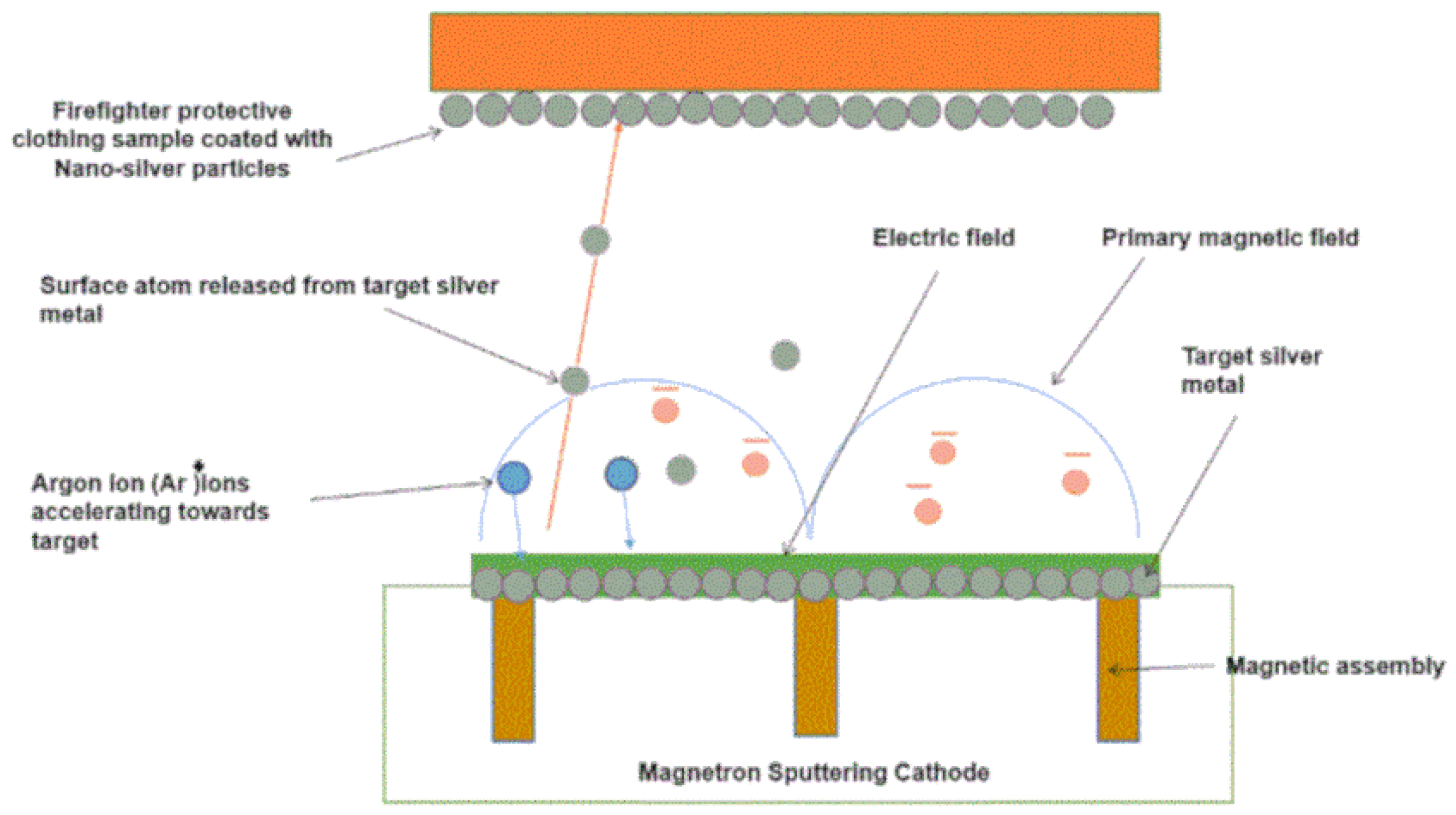
Magnetron sputtering is a physical vapor deposition process, where magnetically confined plasma is generated near the surface of the target metal (silver). Highly energetic ions with a positive charge collide with the surface of the negatively charged target metal. As a result, atoms are ejected from the target material, which then deposit on the surface of the substrate. Magnetron sputtering employs a strong magnetic field to confine electrons near the surface of the target material (metal). In consequence, the efficiency of the ionization process and deposition rate is enhanced, and plasma is created at a lower pressure [44,45]. A schematic diagram of magnetron sputtering is shown in Figure 2. Coating of silver particles on the outer shell of firefighter clothing samples was conducted by the DC-reactive magnetron sputtering equipment (Prevac, Rogów, Poland). At first, the deposition chamber was evacuated at 4 Pascals. The distance between the sample holder and the target (silver metal) was maintained at 15 cm. Later, these samples were placed in a physical vapor deposition (PVD) chamber. The silver particle layer was acquired by sputtering of pure 99.99 percent silver (Ag) in the presence of 100 percent Argon gas floating at a speed of 10 sccm (standard cubic centimeter per minute). The thickness of the layer was 1 um, and it was almost uniform throughout the surface of the fabric. At the time of sputtering, the working pressure was maintained at a pressure of 1.3 Pascals. The power of the magnetron supply was maintained at 615 watts, and the negative substrate bias voltage was maintained at 300 volts. After sputtering, the color of the coated samples changed to silver on the surface of the fabric [43].

2.2. Radiant Heat Transmission Equipment and Measurement Protocol

The X637 B radiant heat transmission machine uses the ISO 6942 standard to measure the transmission of heat through a material or material assembly. The temperature of the room was maintained between 15 °C and 35 °C. The radiant heat testing equipment was employed to investigate the radiant heat flux density through the material or material assembly according to the ISO 6942 standard. The apparatus consisted of six carbide rods serving as radiation heat sources, a small, curved copper plate calorimeter, and a movable test frame with a cooling device and sample holders as shown in Figure 3. At first, calibration was performed when the moveable screen was withdrawn and reverted to a point when a rise in temperature of 30 °C was reached, and the incident heat flux density Qₒ was measured. Afterwards, the sample was affixed to one side of the plate of the sample holder and held in contact with the face of the calorimeter, applying a mass of 200 g. The movable screen was withdrawn, and the starting point of the radiation was recorded. The movable screen was returned to its closed position after a temperature rise of about 30 °C was reached. The size of the sample was 230 mm × 80 mm. The time for temperature accelerations of 12 °C and 24 °C in the calorimeter was determined, and conclusions are mentioned in the form of the radiant heat transmission index (RHTI 12 and RHTI 24), the percentage heat transmission factor (percentage TF Qo) and the transmitted heat flux density Qc [48]. Before experimentation, all samples were pre-conditioned for 24 h at a temperature of 20 °C and had a relative humidity of 65 percent [48]. Three samples were required for testing at each level of heat flux density. Incident heat flux density is evaluated using Equation (1).
Q o = C p R M a . A
A = the area of the copper plate in m2, a = the absorption coefficient of the painted surface of the calorimeter, M = the mass of the copper plate in kg, C p = the specific heat of copper (0.385 kJ/kg°C), R = the rate of the rise in the calorimeter temperature in the linear region in °C/s.
The transmitted flux density Q c , in kW/m2, is evaluated by Equation (2):
Q c = M C p A × K
K = 12 ( R H T I 24 R H T I 12 )
K = Mean rate of escalation of the calorimeter temperature in °C/s in the region between a 12 °C and 24 °C rise.
RHTI 12 = Threshold time in sec when the temperature of the calorimeter increases by 12 °C.
RHTI 24 = Threshold time in sec when the temperature of the calorimeter increases by 24 °C.
The percentage age heat transmission factor [Percentage TF Qo] for the incident heat flux density level is explained by Equation (4) [48]:
% T F Q o = 100 . Q c Q o
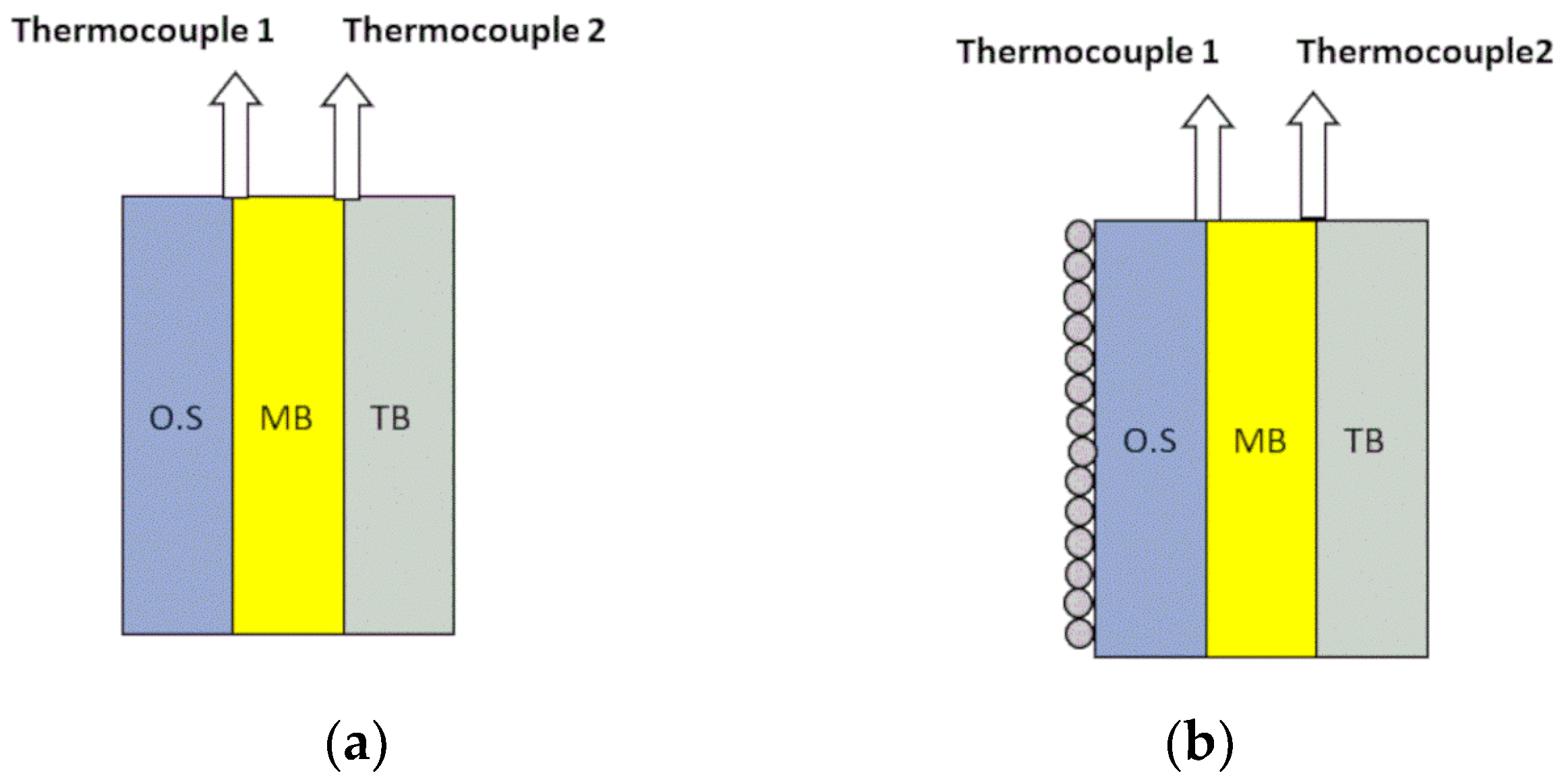
These samples were exposed to a 10 kW/m2 heat flux. To determine the temperature distribution between multilayer clothing assemblies, two K-type thermocouples were placed between the outer shell and moisture barrier and between the moisture barrier and thermal barrier as shown in Figure 4. Thermocouple 1 measures the temperature of the outer shell and thermocouple 2 measures the temperature of the moisture barrier.
To simplify the explanation with theoretical equations, the following assumptions have been made:
  • Transmission of heat takes place in one dimension only.
  • The transfer of mass is negligible.
  • Radiation only penetrates through the exterior shell of the multilayer assembly as almost 95% of incident energy is in the form of radiation that is absorbed after covering a distance equivalent to the outer shell thickness.
  • Optical characteristics like transmissivity, reflectivity and absorptivity are assumed to be constant [21,27,42,43].
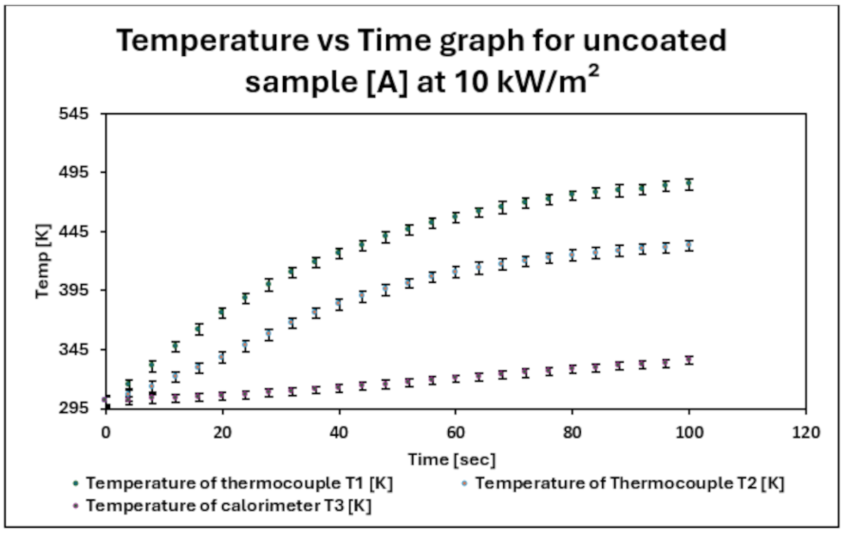
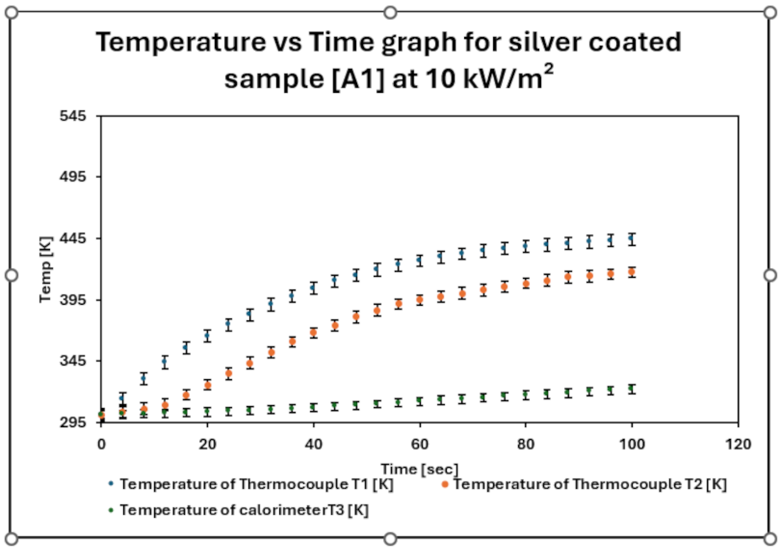
    The temperature of uncoated and silver coated samples against time after exposure to 10 kW/m2 are shown in Figure 5 and Figure 6, respectively.
A quantitative assessment of the rate of the rise in temperature in uncoated samples and silver-coated samples is shown in Table 3. It was noted from Table 3 that the RHTI 24 [sec] value of silver-coated samples was greater compared to uncoated samples A. This indicated that the time for a rise of 24 °C was greater in silver-coated samples as compared to uncoated samples. The transmitted heat flux density Qc [kW/m2] was lower in the case of silver-coated samples as compared to uncoated samples. The lower value of transmitted heat flux density indicated that a lower amount of radiant heat flux density was passed through silver-coated samples for a given value of time. Similarly, the lower value of the percentage heat transmission factor for silver-coated samples indicated that a lower amount of heat was transmitted in silver-coated samples. This might be due to the good reflective properties of silver particles, which dissipated the external radiant heat flux. The reflective property of silver-coated samples was measured with a Mid-Infrared Integrator with an FTIR spectrometer as mentioned in Table 3.
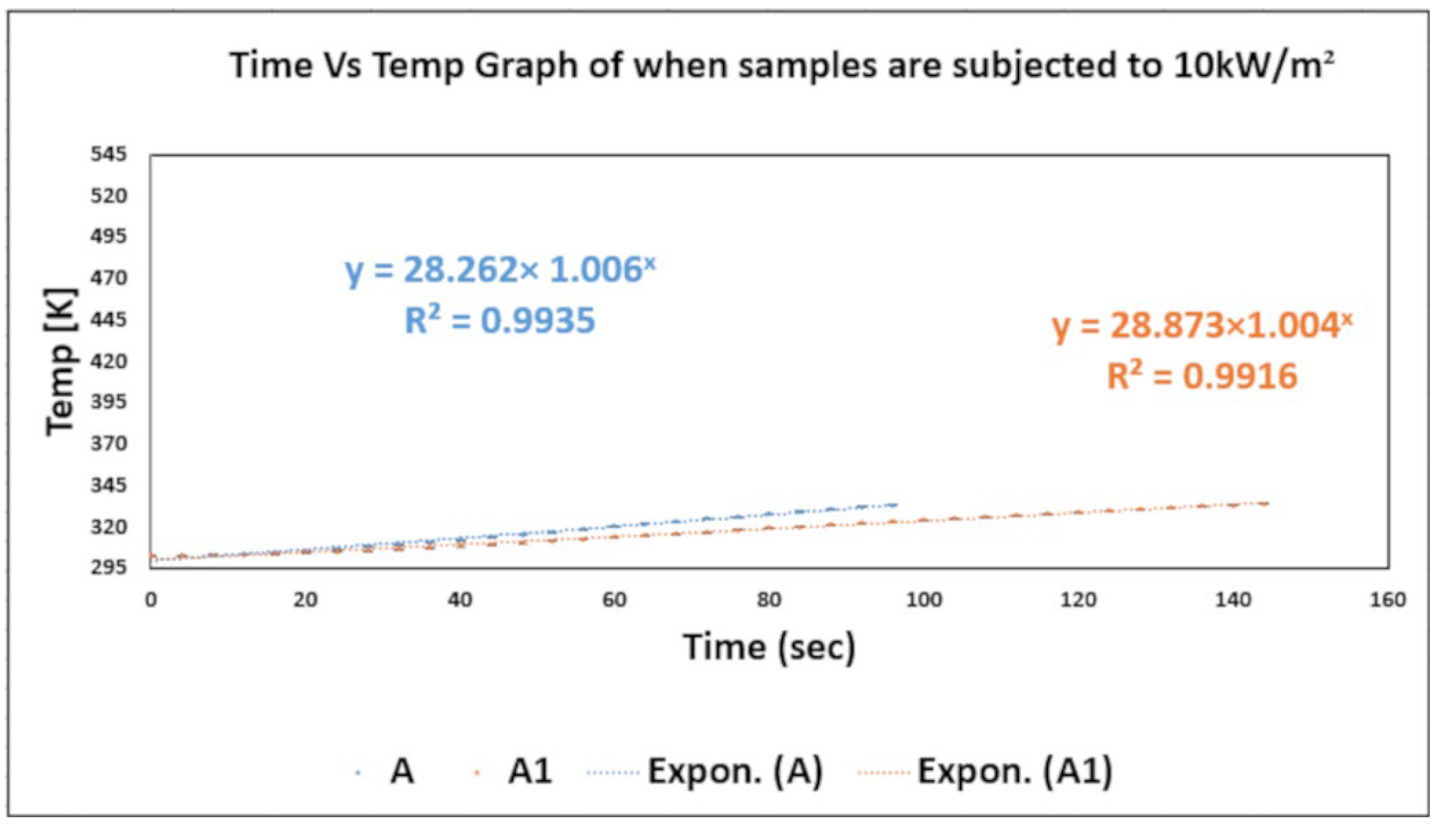
Figure 7 shows the time vs. temperature values of uncoated and silver-coated samples when subjected to 10 kW/m2. It was noted that a flatter curve was obtained for silver-coated samples A1. On the other hand, a relatively steep curve was obtained for uncoated samples A. This indicated that the rate of the rise in temperature of silver-coated samples A1 took place at a slower rate as compared to uncoated samples A [43].

3. Transmission of Heat from Heating Source to Firefighter Clothing Assembly

As described earlier, uncoated and silver-coated fabric assemblies were subjected to a heat flux of 10 kW/m2 with the help of a heating source. This process of heat transfer in firefighter clothing assemblies due to heat fluxes induced by heating rods can be represented with the help of an energy equation as mentioned by Su et al. [27,42]:
ρ f b C p f b . T t = x λ f b T x + q r a d a b s x
where ρ f b , C p f b and λ f b are the density, specific heat capacity and thermal conductivity of firefighter fabric, respectively. q r a d a b s is the absorbed portion of radiant heat flux from the heating source to the outer shell. Equation (6) can also be written as follows:
C p f b x . ρ f b x T ( x , t ) t = λ f b x . T ( x , t ) + Q r a d a b s ( x , t ) x
where T ( x , t ) is the temperature field under investigation and t is the total time during which we investigate the temperature field. This equation is a second-order transient parabolic differential equation. It was assumed that textile material was homogeneous and isotropic. Therefore, the values of λ f b , C p f b and ρ f b are assumed to be constant. designates the Vector Hamilton operator in a Cartesian coordinate system. Q r a d a b s ( x , t ) is the part of radiation absorbed by the outer shell from the radiant heat source. It was assumed that the textile material was homogeneous and isotropic. Therefore, the values of λ f b , C p f b and ρ f b are assumed to be constant [49,50,51,52].
It is also possible to rewrite Equation (7) in the following way:
C p f b x . ρ f b x T ( x , t ) t = λ f b . T ( x , t ) + Q r a d a b s ( x , t ) x
where the symbol designates the Laplace operator T = 2 T ( x , t ) x i 2 .
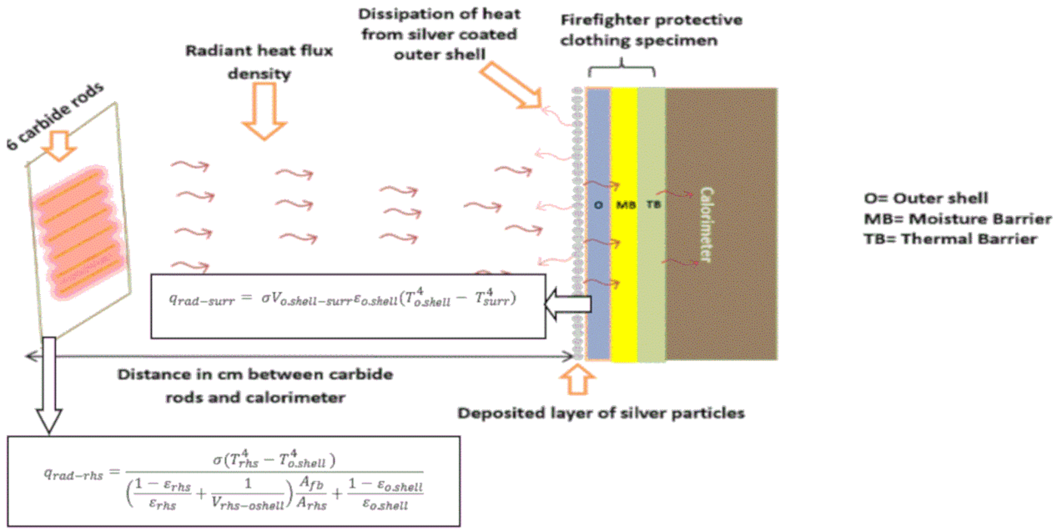
The thermal energy from the heating source to the surface of the cloth is transported due to thermal radiation and convection of air. In this scenario, the mode of radiation is dominant as compared to convection. The radiant heat transmission between the heating source and the outer shell is dependent on the differentiation of temperature and radiation view factor, as shown in Figure 8 [27,42,43].

3.1. Numerical Solution

To solve Equation (6), the finite difference method was utilized. The implicit method was employed for the discretization of the second-order parabolic differential equation. The values of temperature at discrete points (xi and tj) are indicated by T i j .
Due to the scattering and absorption of radiation, Beer’s law was utilized to explain the extinction of the incident thermal radiation ( Q r a d ) in multilayer fabric systems [42,53]. Beer’s law is mostly used for liquid solutions; however, it can also be utilized for porous mediums like textiles [43].
Q r a d a b s ( x , t ) x = [ Q r a d ] ( e γ f b i x ) γ f b
Q r a d a b s ( x , t ) x = [ q r a d r h s q r a d s u r r ] ( e γ f b i x ) γ f b
Q r a d a b s x , t x = σ ( T r h s 4 T i j 4 ) 1 ε r h s ε r h s + 1 V r h s o . s h e l l A f b A r h s + 1 ε o . s h e l l ε o . s h e l l σ V o . s h e l l s u r r . ε o . s h e l l T i . j 4 T s u r r 4 ( e γ f b i x )
σ is the Stefan–Boltzmann constant (5.678 × 10⁻⁸ W/m2K4).
Trhs is the temperature of the radiant heat source in K;
Tsurr is the temperature of the surrounding atmosphere in K;
Afb is the area of firefighter fabric in m2;
Arhs is the area of the radiant heat source in m2;
ε r h s is the emissivity of the radiant heat source;
ε o . s h e l l is the emissivity of the outer shell;
Vrhs-o.shell is the view factor from the radiant heat source towards the outer shell [27,42];
Vo.shell-surr is the view factor from the outer shell towards the surrounding atmosphere.
V o . s h e l l r h s . A f b = V r h s o . s h e l l . A r h s
V o . s h e l l s u r r + V o . s h e l l r h s = 1
The view factor is a fraction of the radiation leaving one surface which is received by another surface. It was assumed that the heating source and exterior shell were parallel coaxial disks of unequal radii [42,54].
V r h s o . s h e l l = 1 2 [ S { s 2 4 r o . s h e l l r r h s 2 } 1 / 2 ]
S = 1 + 1 + R o . s h e l l 2 R r h s 2
R r h s = r r h s L
R o . s h e l l = r o . s h e l l L
L is the distance between the heating rods and the multilayer clothing assembly in meters, r o . s h e l l is the radius of the outer shell and r r h s is the radius of the heating source.
γ f b is the extinction coefficient of the outer shell, which is illustrated by the following equation:
γ f b = ln ( τ ) h o . s h e l l
where τ is the transmissivity of the outer shell and h s h e l l is the thickness of the outer shell [49]. Some important values are mentioned in Table 4 [43].
Equation (7) can also be written as
T ( x , t ) t = λ f b C p . f b x . ρ f b ( x ) . 2 T x 2 + Q r a d ( ( e γ f b i x ) ) γ f b C p . f b x . ρ f b ( x )
Partial derivatives in Equation (15) were substituted by an implicit finite divided scheme, generating a discrete description related to position xi and time tj:
T i j + 1 T i j t = λ f b C p . f b . ρ f b . T i + 1 j + 1 2 T i j + 1 + T i 1 j + 1 x 2 + Q r a d ( ( e γ f b i x ) ) γ f b C p . f b . ρ f b
T i j + 1 T i j = λ f b x 2 . C p . f b . ρ f b . t T i + 1 j + 1 2 T i j + 1 + T i 1 j + 1 + Q r a d ( e γ f b i x ) γ f b . t C p . f b . ρ f b
T i j = k T i 1 j + 1 + 1 + 2 k T i j + 1 k T i + 1 j + 1 Q r a d ( e γ f b i x ) γ f b . t C p . f b . ρ f b
T i j + Q r a d ( e γ f b i x ) γ f b . t C p . f b . ρ f b = k T i 1 j + 1 + 1 + 2 k T i j + 1 k T i + 1 j + 1
For further solutions, the Thomas algorithm method was employed to solve the above-mentioned equation. The Thomas algorithm is a tridiagonal matrix algorithm, utilized for the solution of second-order partial differential equations. It provides an effective way to resolve tridiagonal systems of equations during the discretization of second-order partial differential equations. The Gaussian elimination method is streamlined by this algorithm [56] as follows:
k = λ f b . t x 2 . C p . f b . ρ f b
I n t e r v a l   o f   n o d e x = T h i c k n e s s   o f   f a b r i c N u m b e r   o f   n o d e s
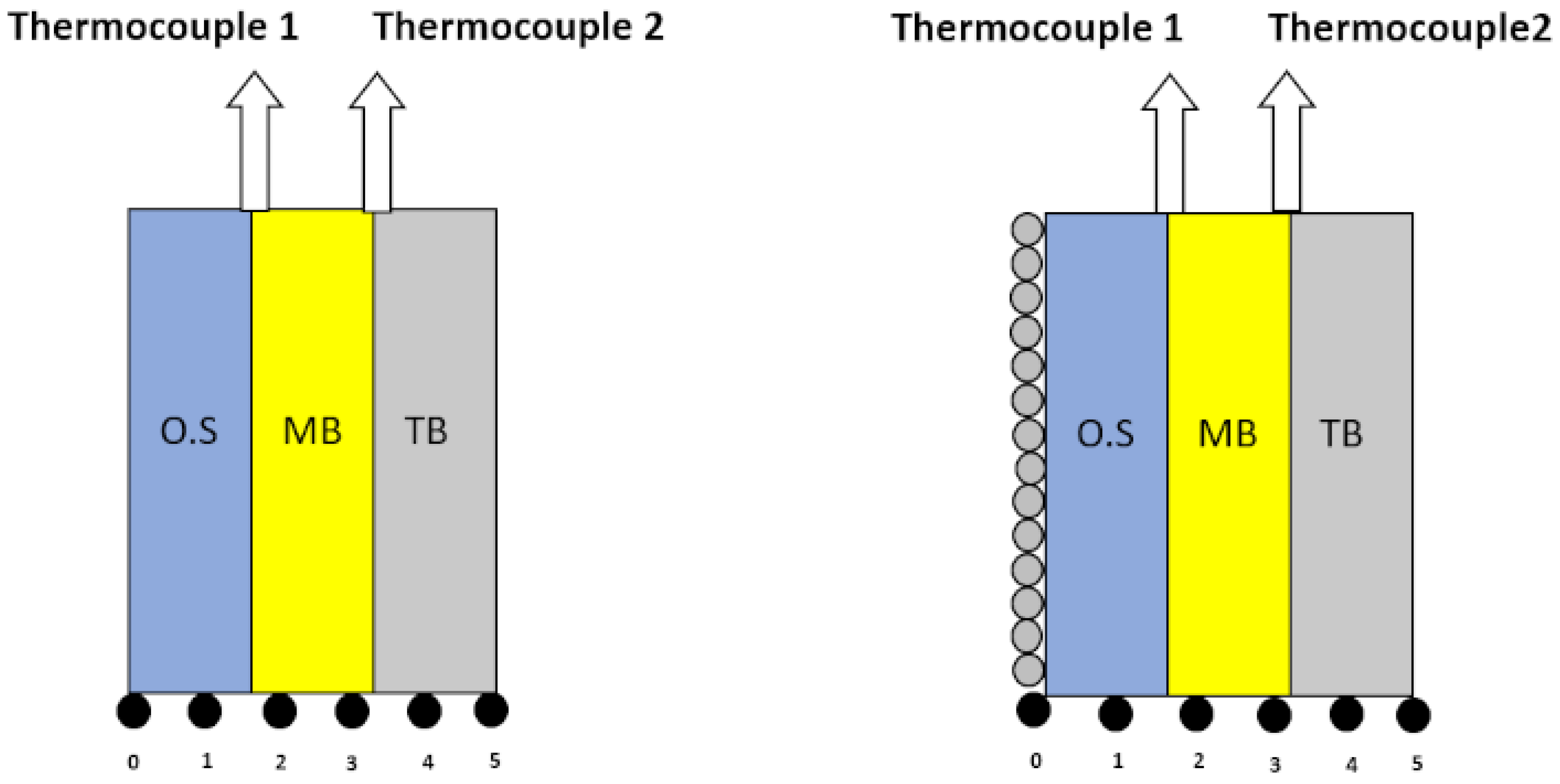
The fabric assembly is divided into 5 nodes as seen in Figure 9.
For solving partial differential equations, a node means a point in the discretized domain where the computation of solutions took place. For implicit methodology, the solution at a particular node is dependent on the solution at the adjacent neighboring nodes, and equations associated with solutions must be resolved in a simultaneous manner. Due to this reason, a system of equations was generated that must be resolved in an iterative manner, and the solution at every node was updated till convergence was achieved [43,57].
Number of time steps = T i m e f i n a l T i m e i n i t i a l t = 100   s e c 0   s e c 1 = 100 .
Interval of time Δt = 1 sec.
T i j corresponds to the temperature at node i.
x = i . x and t = j . t .

Boundary Conditions

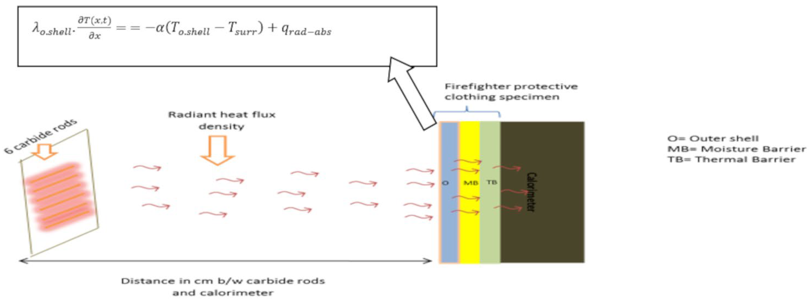
The initial temperature was 301.45 K and its schematic diagram is shown in Figure 10 and Figure 11, respectively.
λ o . s h e l l . T ( x , t ) x = α T o . s h e l l T s u r r + q r a d a b s
where α represents the coefficient of heat transfer, T s u r r is the temperature of the surrounding atmosphere and q r a d a b s is the part of radiation absorbed by the outer shell [27,42].
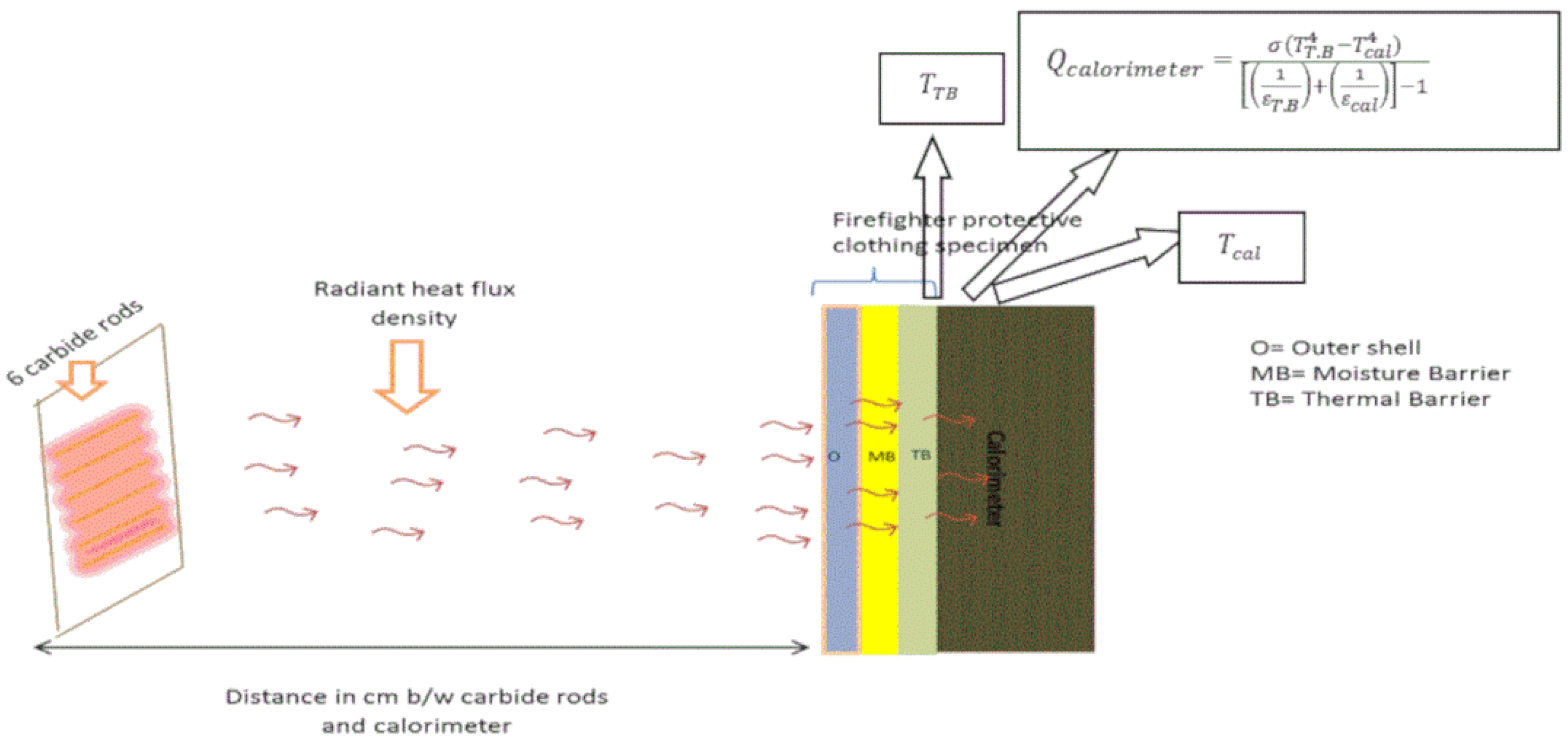
λ T . B . T ( x , t ) x = Q c a l o r i m e t e r λ a i r . T x
Q c a l o r i m e t e r = σ ( T T . B 4 T c a l 4 ) 1 ε T . B + 1 ε c a l 1
ε T . B is the emissivity of the thermal barrier and ε c a l is the emissivity of the calorimeter. T T . B is the temperature of the thermal barrier in Kelvin and T c a l is the temperature of the calorimeter in Kelvin [27].
The distribution of temperature at different nodes in different intervals of time for uncoated and silver-coated samples is depicted in Figure 10 and Figure 11, respectively.

4. Results and Discussion

Distributions of temperatures for uncoated and silver-coated samples were determined at different intervals of time with the help of numerical solutions, and later, these results were compared with each other.
It can be witnessed from Figure 12 and Figure 13 that there was a sequential increment in the rise in temperature for different curves with an increase in time. However, this increment was not in a linear form. It was also noticed that as the number of nodes increased, there was a decline in the values of temperature for the same time period. This indicates a decline in temperature values with an increase in the thickness of firefighter clothing assemblies for both uncoated samples A and silver-coated samples A1.
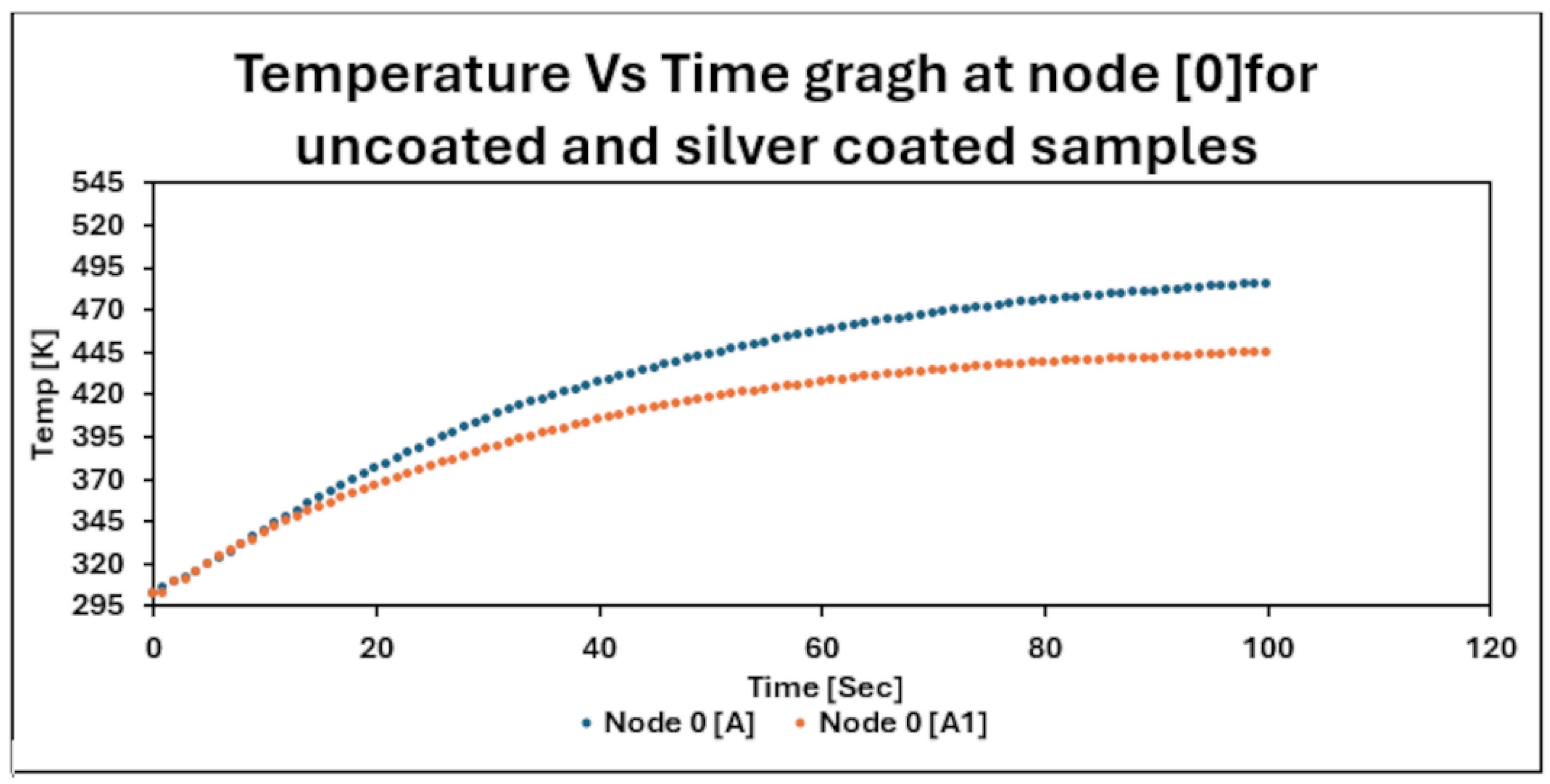
It can be noticed from Figure 14 that in the first sixteen seconds, the curves of uncoated samples A and silver-coated samples A1 overlap with each other. Afterwards, a gap appears between the curves of silver-coated and uncoated samples. This gap continued increasing with the increase in time.
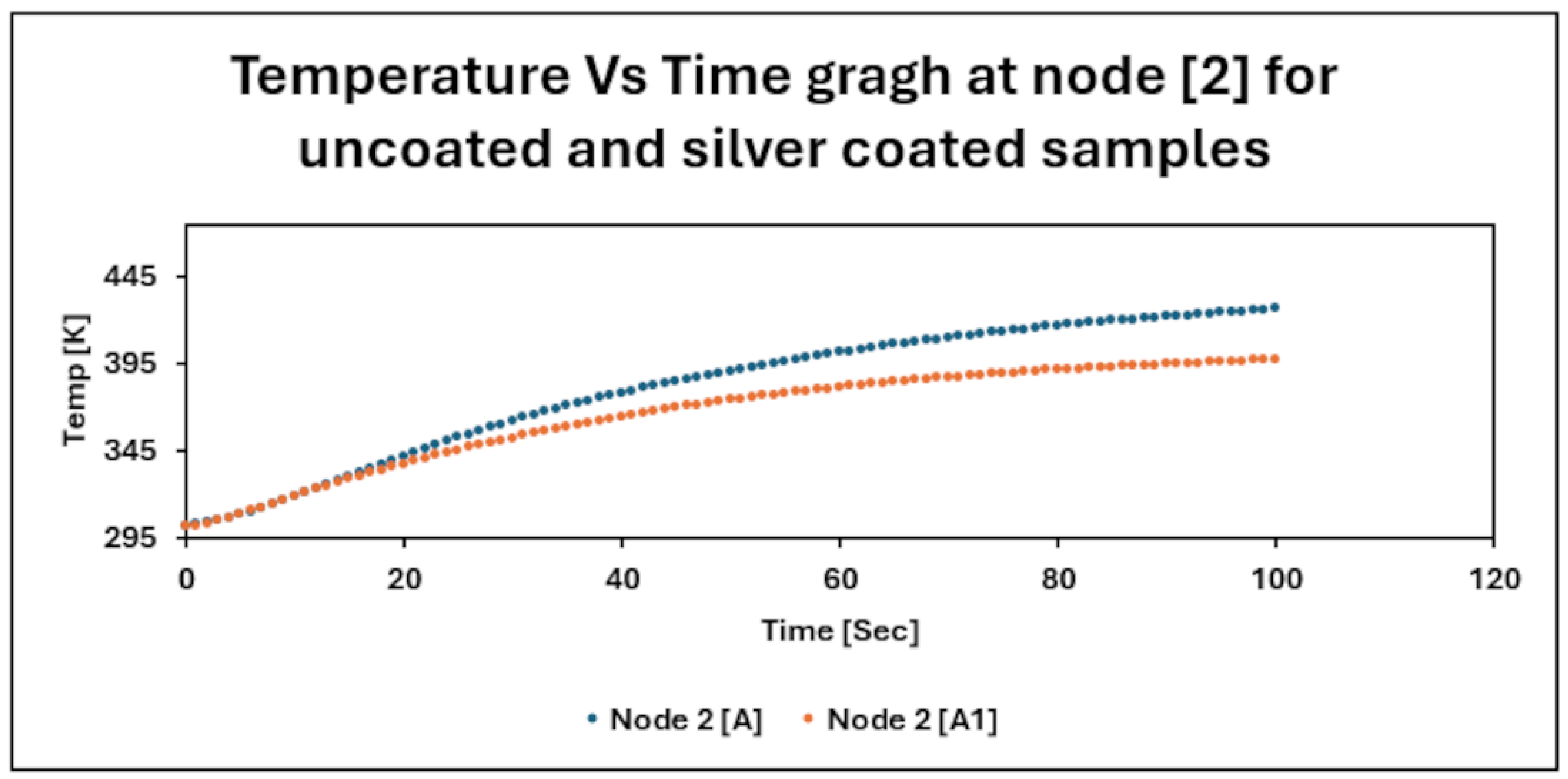
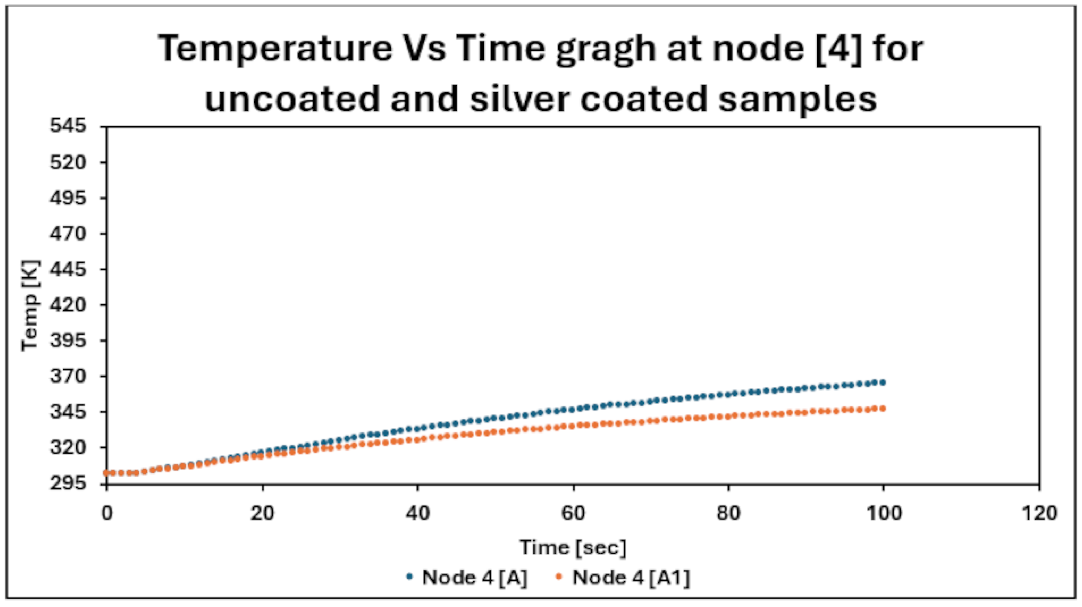
It can be witnessed from Figure 15, Figure 16, Figure 17 and Figure 18 that in the first 15 s, both curves of uncoated and silver-coated samples superimposed each other. Afterwards, the curve of uncoated samples started to get steeper as compared to the curves of silver-coated samples. It was also observed that as the number of nodes increased, the curve of both uncoated and silver-coated samples became flatter as compared to previous nodes. The slackness in the curve indicates that the rate of the rise in temperature takes place slowly. Consequently, the thermal protective performance will be better because less heat is transmitted towards the fabric assembly.
It is evident from Figure 19 that the pattern of the curves for the uncoated and silver-coated samples is almost the same after the initial 5 s. Later, the curve of uncoated samples starts to rise by creating a gap between the curves of uncoated A and silver-coated samples A1. The wideness of this gap between the two curves increases till 100 s. This indicates the better thermal protective performance of silver-coated samples A1.
It can be inferred that the numerical model solution predicts the temperature distribution at different nodes for uncoated samples A and silver-coated samples A1 at different intervals of time. This model also shows the silver-coated samples A1 incur a less steep curve of temperature values as compared to uncoated samples A at different nodes. This flatness of the curve was also witnessed in the case of silver-coated samples A1 for experimental work. With the help of the numerical model, it was possible to estimate the temperature distribution at different places along with the thickness of the fabric, which was not possible in experimental work.

5. Conclusions

Firefighters are always putting their lives in danger when performing their duties. For firefighter protective clothing, thermal protective performance is the most important property. It is the capability of firefighter clothing to protect firefighters from second-degree burns. The thermal protective performance can be improved by metallic silver coatings through magnetron sputtering. It was noted from a radiant heat transmission machine that the rate of the rise in temperature was low in silver-coated samples because of their excellent reflective properties. A numerical model and its solutions were established using appropriate equations for the transmission of heat. The distribution of temperature through the multilayer sandwich structure was determined with the help of the numerical model and its solutions. Previously, no attempt was made to predict the distribution of temperature for firefighter clothing coated with low-emissivity silver particles. The structure of the sandwich assembly was divided into five nodes and finite difference methodology was selected to solve partial differential equations. Discretization of the partial differential was carried out by implicit methodology. The Thomas algorithm method was used for further solutions of the equations. Thus, the temperature distribution of multilayer firefighter ensembles was studied through these techniques. The outcomes of this study might be beneficial for researchers and industrial partners to predict the thermal protection of firefighter protective clothing with lower-emissivity coatings.

Author Contributions

Conceptualization J.N., A.M., Z.K. and A.H.; methodology J.N. and A.M.; software J.N. and M.A.; validation J.N., A.M., Z.K. and A.H.; Investigation J.N., A.M., Z.K. and A.H.; resources Z.K., A.H. and A.M.; data curation J.N. and A.M.; and writing—original draft preparation J.N. and A.M.; review Z.K., A.H. and A.M.; and editing J.N., A.M. and M.A.; visualization J.N. and A.M.; supervision Z.K., A.M. and A.H. All authors have read and agreed to the published version of the manuscript.

Funding

This research received no external funding.

Institutional Review Board Statement

Not applicable.

Informed Consent Statement

Not applicable.

Data Availability Statement

Data is contained within the article.

Acknowledgments

The authors would like to thank Tomas Vit, Ing Ondreg Burian and Michal Krejcik for their valuable recommendations and the Vochoc company for providing the samples.

Conflicts of Interest

The authors declare no conflicts of interest.

References

  1. Holmer, I. How is performance in heat affected by clothing. Text. Bioeng. Inform. Symp. Proc. 2008, 1, 700–705. [Google Scholar]
  2. Keiser, C.; Rossi, R.M. Temperature analysis for the prediction of steam formation and transfer in multilayer thermal protective clothing at low level thermal radiation. Text. Res. J. 2008, 78, 1025–1035. [Google Scholar] [CrossRef]
  3. Bajaj, P.; Sengupta, A.K. Protective clothing. Text. Prog. 1992, 22, 1–110. [Google Scholar] [CrossRef]
  4. Jin, L.; Hong, K.; Yoon, K. Effect of Aerogel on Thermal Protective Performance of Fire-Fighter Clothing. J. Fiber Bioeng. Inform. 2013, 6, 315–324. [Google Scholar]
  5. Nayak, R.; Houshyar, S.; Padhye, R. Recent trends and future scope in the protection and comfort of fire-fighters’ personal protective clothing. Fire Sci. Rev. 2014, 1, 2014. [Google Scholar] [CrossRef]
  6. Song, G.; Paskaluk, S.; Sati, R.; Crown, E.M.; Dou, J. Thermal protective performance of protective clothing used for low radiant heat protection. Text. Res. J. 2010, 81, 311–323. [Google Scholar] [CrossRef]
  7. Mäkinen, H. Firefighter Protective Clothing. In Textile for Protection; Woodhead Publishing: Sawston, UK, 2005; pp. 622–647. [Google Scholar]
  8. Song, G.; Chitrphiromsri, P.; Ding, D. Numerical Simulations of Heat and Moisture Transport in Thermal Protective Clothing Under Flash Fire Conditions. Int. J. Occup. Saf. Ergon. 2008, 14, 89–106. [Google Scholar] [CrossRef] [PubMed]
  9. Fu, M.; Weng, W.; Yuan, H. Thermal Insulations of multilayer clothing systems measured by a bench scale test in low level heat exposures. Int. J. Cloth. Sci. Technol. 2013, 26, 412–423. [Google Scholar] [CrossRef]
  10. Min, K.; Son, Y.; Kim, C.; Lee, K.; Hong, K. Heat and moisture transfer from skin to environment through fabrics: A mathematical model. Int. J. Heat Mass Transf. 2007, 50, 5292–5304. [Google Scholar] [CrossRef]
  11. Venkataraman, M.; Mishra, R.; Kotresh, T.M.; Sako, T. Effect of compressibility on heat transport phenomena in aerogel-treated nonwoven fabrics. J. Text. Inst. 2016, 107, 1150–1158. [Google Scholar] [CrossRef]
  12. Stabkovic, S.B.; Popvic, D.; Poparic, G.B. Thermal properties of textile fabrics made of natural and regenerated cellulose fibers. Polym. Test. 2008, 27, 41–48. [Google Scholar] [CrossRef]
  13. Jin, L.; Cao, M.L.; Yu, W.; Hu, J.Y.; Yoon, K.J.; Park, P.K.; Li, Y. New approaches to evaluate performance of firefighter protective clothing. Fire Technol. 2018, 54, 1283–1307. [Google Scholar] [CrossRef]
  14. Fu, M.; Weng, W.; Yuan, H. Effects of multiple air gaps on the thermal performance of firefighter protective clothing under low-level heat exposure. Text. Res. J. 2013, 84, 968–978. [Google Scholar] [CrossRef]
  15. Shaid, A.; Wang, L.; Padhye, R. The thermal protection and comfort properties of aerogel and PCM-coated fabric for firefighter garment. J. Ind. Text. 2015, 45, 611–625. [Google Scholar] [CrossRef]
  16. Ali, A.H.M.; Mohmmed, R. A review of the firefighting fabrics for flashover temperature. Int. J. Eng. Sci. Res. Technol. 2015, 4, 247–257. [Google Scholar]
  17. Raslan, W.M. Ultraviolet Protection, Flame Retardancy and Antibacterial Properties of Treated Polyester Fabric Using Plasma-Nano Technology. Mater. Sci. Appl. 2011, 2, 1432–1442. [Google Scholar] [CrossRef]
  18. Azom, “Silver (Ag), Properties and Applications,” Azo Materials. 2013. Available online: https://www.azom.com/article.aspx?ArticleID=9282 (accessed on 24 June 2023).
  19. Negawao, T.A. Analyzing and Modelling of Comfort and Protection Properties of Firefighters Protective Clothing. Master’s Thesis, Istanbul Technical University, Istanbul, Turkey, 2015. [Google Scholar]
  20. ISO 6942; Protective Clothing—Protection against Heat and Fire—Method of Test: Evaluation of Materials and Material Assemblies when Exposed to a Source of Radiant Heat. International Organization for Standardization: Geneva, Switzerland, 2002.
  21. Torvi, D. Heat Transfer in Thin Fibrous Materials under High Heat Flux Conditions. Ph.D. Thesis, University of Alberta, Edmonton, AB, Canada, 1997. [Google Scholar]
  22. Kukuck, S.; Prasad, K. Thermal Performance of Fire Fighters’ Protective Clothing. 3. Simulating a TPP Test for Single-Layered Fabrics; National Institute of Standards and Technology: Gaithersburg, MD, USA, 2003. [Google Scholar]
  23. Zhu, F.L.; Zhang, W.; Song, G. Heat transfer in a cylinder sheathed by flame-resistant fabrics exposed to convective and radiant heat flux. Fire Saf. J. 2008, 43, 401–409. [Google Scholar] [CrossRef]
  24. Mercer, G.N.; Sidhu, H. A theoretical investigation into phase change clothing benefits for firefighters under extreme conditions. Chem. Prod. Process Model. 2003, 4, 289–305. [Google Scholar] [CrossRef]
  25. Song, G.; Barker, R.L.; Hamouda, H.; Kuznetsov, V. Modeling the thermal protective performance of heat resistant garments in flash fire exposures. Text. Res. J. 2004, 74, 1033–1040. [Google Scholar] [CrossRef]
  26. Ghazy, A.; Bergstrom, D.J. Numerical simulation of heat transfer in firefighters’ protective clothing with multiple air gaps during flash fire exposure. Numer. Heat Transf. Part A Appl. 2012, 61, 569–593. [Google Scholar] [CrossRef]
  27. Su, Y.; He, J.; Li, J. Modelling transmitted and stored energy in multilayer protective clothing under low level radiant exposure. Appl. Therm. Eng. 2016, 93, 1295–1303. [Google Scholar] [CrossRef]
  28. Su, Y.; He, J.; Li, J. A model of heat transfer in firefighting protective clothing during compression after radiant heat exposure. J. Ind. Text. 2016, 47, 2128–2152. [Google Scholar] [CrossRef]
  29. Su, Y.; Li, R.; Song, R.; Li, J.; Xiang, C. Modeling steam heat transfer in thermal protective clothing under hot steam exposure. Int. J. Heat Mass Transf. 2018, 120, 818–829. [Google Scholar] [CrossRef]
  30. Ackerman, M.; Crown, E.; Dale, J.; Murtaza, G.; Gonzalese, J. Development of a test apparatus/method and material specifications for protection from steam under pressure. In Performance of Protective Clothing and Equipment Emerging Issues and Technologies; ASTM International: West Conshohocken, PA, USA, 2012; Volume 9. [Google Scholar]
  31. Yoo, H.; Hu, S.; Kim, E.A. Effects of heat and moisture transport in fabrics and garments determined with a vertical plates wearing skin model. Text. Res. J. 2000, 70, 542–549. [Google Scholar] [CrossRef]
  32. Desruelle, A.V.; Schmid, B. The steam laboratory of the Institut de Médecine Navale du Service de Santé des Armées: A set of tools in the service of the French Navy. Eur. J. Appl. Physiol. 2004, 92, 630–635. [Google Scholar] [CrossRef] [PubMed]
  33. Sati, R.; Crown, E.M.; Ackerman, E.M.; Gonzalez, J. Protection from steam at high pressures: Development of a test device and protocol. Int. J. Occup. Saf. Ergon. JOSE 2008, 14, 29–41. [Google Scholar] [CrossRef]
  34. Zhu, R.; Zhang, W. Modeling heat transfer for heat-resistant fabrics considering pyrolysis effect under an external heat flux. J. Fire Sci. 2009, 27, 81–96. [Google Scholar] [CrossRef]
  35. Yang, J.; Su, Y.; Song, G.; Li, R.; Xiang, C. A new approach to predict heat stress and skin burn of firefighter under lowlevel thermal radiation. Int. J. Therm. Sci. 2019, 145, 106021. [Google Scholar] [CrossRef]
  36. Shakeriaski, F.; Ghodrat, M.; James, D. Experimental and numerical studies on efficiency characterization of firefighters’ protective clothing: A review. J. Text. Inst. 2022, 113, 2549–2568. [Google Scholar] [CrossRef]
  37. Mandal, S.; Annaheim, S.; Greve, J. Modeling for predicting the thermal protective and thermo-physiological comfort performance of fabrics used in firefighters’ clothing. Text. Res. J. 2018, 89, 2836–2849. [Google Scholar] [CrossRef]
  38. Puszkarz, A.K.; Machnowski, W. Simulations of heat transfer through multilayer protective clothing exposed to flame. AUTEX Res. J. 2022, 22, 298–304. [Google Scholar] [CrossRef]
  39. Fonseca Malaquias, A.; Neves, S.; Camp, J.B.L.M. The impact of water on firefighter protective clothing thermal performance and steam burn occurrence in firefighters. Fire Saf. J. 2022, 127, 103506. [Google Scholar] [CrossRef]
  40. Kabir, H.; Aghdam, M. A robust Bézier based solution for nonlinear vibration and post-buckling of random checkerboard graphene nano-platelets reinforced composite beams. Compos. Struct. 2019, 212, 184–198. [Google Scholar] [CrossRef]
  41. Bert, C.W.; Malik, M. Differential quadrature powerful new technique for analysis of composite structure. Compos. Struct. 1997, 39, 179–189. [Google Scholar] [CrossRef]
  42. Su, Y.; He, J.; Li, J. Numerical simulation of heat transfer in protective clothing with various heat exposures distances. J. Text. Inst. 2016, 108, 1412–1420. [Google Scholar] [CrossRef]
  43. Naeem, J. Thermal Protetcive Performance of Fitrefighter Protective Clothing. Ph.D. Thesis, Technical University of Liberec, Liberec, Czech Republic, 2020. [Google Scholar]
  44. Anon, “Magnetron Sputtering”. 2018. Available online: https://angstromengineering.com/tech/magnetron-sputtering/ (accessed on 24 June 2022).
  45. Anon, “Magnetron Sputtering Solutions”. 2020. Available online: https://www.dentonvacuum.com/products-technologies/magnetron-sputtering/ (accessed on 24 June 2022).
  46. Shohet, J.L. Metal Deposition: Plasma-Based Processes. In Encyclopedia of Plasma Technology, 1st ed.; Taylor and Francis: New York, NY, USA, 2016; p. 726. [Google Scholar]
  47. Shi, F. Introductory Chapter: Basic Theory of Magnetron Sputtering; IntechOpen: London, UK, 2018; Volume 93, pp. 1295–1303. [Google Scholar]
  48. Dr.-Ing. Georg Wazau Meß- + Prüfsysteme GmbH. Combustion Behavior Test Equipment; Wazau: Berlin, Germany, 2002. [Google Scholar]
  49. Cengel, Y.A.; Ghajar, A.; Ma, H. Heat and Mass Transfer Fundamentals and Applications, 4th ed.; McGraw-Hill: New York, NY, USA, 2011. [Google Scholar]
  50. Feistauer, M.; Najzar, K. Finite Element Approximation of a Problem with a Nonlinear Boundary Condition. Numer. Math. 1998, 78, 403–425. [Google Scholar] [CrossRef]
  51. Mlýnek, J.; Knobloch, R. Model of Shell Metal Mould Heating in the Automotive Industry. J. Appl. Math. 2018, 63, 111–124. [Google Scholar]
  52. Křížek, M.; Liu, L. Finite Element Analysisof a Radiation Heat Transfer Problem. J. Comput. Math. 1998, 6, 327–336. [Google Scholar]
  53. Martinez, I. “Radiative View Factors”. 1995. Available online: http://imartinez.etsiae.upm.es/~isidoro/tc3/Radiation%20View%20factors.pdf (accessed on 25 April 2022).
  54. Modest, M.F. Radiative Heat Transfer; McGraw-Hill: New York, NY, USA, 1993. [Google Scholar]
  55. ASTM F2731; Test Method for Measuring the Transmitted and Stored Energy of Firefighter Protective Clothing Systems. American Standard for Testing Materials: West Conshohocken, PA, USA, 2011.
  56. Higham, N.J. Accuracy and Stability of Numerical Algorithms, 2nd ed.; SIAM: Philadelphia, PA, USA, 2002. [Google Scholar]
  57. Fanghor, H. Solving Partial Differential Equations, Engineering and Environment. Lectures, University of South Hampton, UK, 2012. Available online: https://www.southampton.ac.uk/~fangohr/teaching/comp6024/comp6024-pdes.pdf (accessed on 25 April 2022).
Figure 1. Schematic diagram of arrangement of fabric assemblies along with their codes.
Micro 04 00023 g001
Figure 2. Schematic diagram of magnetron sputtering [46,47].
Micro 04 00023 g002
Figure 3. Radiation heat testing equipment [43].
Micro 04 00023 g003
Figure 4. (a) Uncoated samples. (b) Silver-coated samples [43].
Micro 04 00023 g004
Figure 5. Temperature of uncoated samples with respect to time when samples are exposed to 10 kW/m2 [43].
Micro 04 00023 g005
Figure 6. Temperature of silver-coated samples with respect to time when samples are exposed to 10 kW/m2 [43].
Micro 04 00023 g006
Figure 7. Temperature of firefighter samples with respect to time when samples are exposed to 10 kW/m2 [43].
Micro 04 00023 g007
Figure 8. Schematic diagram showing equations involved in transmission of heat from heat source towards outer shell [43].
Micro 04 00023 g008
Figure 9. Schematic diagram of uncoated and silver-coated samples with representation of nodes.
Micro 04 00023 g009
Figure 10. Schematic diagram showing boundary condition of outer shell [43].
Micro 04 00023 g010
Figure 11. Schematic diagram showing equation for boundary condition of thermal barrier [43].
Micro 04 00023 g011
Figure 12. Temperature distribution in uncoated samples with respect to time [43].
Micro 04 00023 g012
Figure 13. Temperature distribution in silver-coated samples with respect to time [43].
Micro 04 00023 g013
Figure 14. Comparison of temperature distribution of uncoated and silver-coated samples at node [0] [43].
Micro 04 00023 g014
Figure 15. Comparison of temperature distribution of uncoated and silver-coated samples at node [1] [43].
Micro 04 00023 g015
Figure 16. Comparison of temperature distribution of uncoated and silver-coated samples at node [2] [43].
Micro 04 00023 g016
Figure 17. Comparison of temperature distribution of uncoated and silver-coated samples at node [3] [43].
Micro 04 00023 g017
Figure 18. Comparison of temperature distribution of uncoated and silver-coated samples at node [4] [43].
Micro 04 00023 g018
Figure 19. Comparison of temperature distribution of uncoated and silver-coated samples at node [5] [43].
Micro 04 00023 g019
Table 1. Specification of samples [43].
Sr NoName of SampleCodeMaterial SpecificationWeave DesignGSM
[g/m2]
Thickness
[mm]
1Outer shellO70% Conex, 23% Lenzing FR, 5% Twaron, 2% BeltronRip stop 225 ± 2.10.44 ± 0.01
2Outer shell (1 μm thickness)O (1)70% Conex, 23% Lenzing FR, 5% Twaron, 2% BeltronRip stop234 ± 1.80.441 ± 0.02
3Moisture barrierMBFace fabric, 50%/50% Kermel/viscose FR, PTFE membraneNon-woven120 ± 1.80.55 ± 0.01
4Thermal barrierTBThermo: Para Aramid Inner futter: 50% Meta aramid, 50% viscoseNon-woven200 ± 2.31.8 ± 0.02
Table 2. Arrangement of fabric assemblies along with their codes [43].
Sr NoFabric AssemblyFabric CodeFabric Weight [g/m2]Thickness
[mm]
1Outer shell (O) + moisture barrier (MB) + thermal barrier (TB)A545 ± 3.12.79 ± 0.02
2Outer shell (O1) + moisture barrier (MB) + thermal barrier (TB)A1554 ± 3.52.791 ± 0.03
Table 3. Calorimetric properties of samples.
Sr NoSamplesQo [kW/m2]RHTI 12 [sec]RHTI 24 [sec]RHTI24-RHTI 12 [sec]Qc [kW/ m2][%] Age TF QoReflectivity
1A10.046.30 ± 0.9477.20 ± 0.9230.902.153 ± 0.00121.60[0.09]
2A110.063.3 ± 0.86110.50 ± 0.7247.201.415 ± 0.00314.20[0.46]
Table 4. Firefighter clothing parameters [43].
SymbolsValues
ε o . s h e l l (uncoated)0.86
ε o .   s h e l l (silver coated)0.52
ε r h . s 0.98 [55]
A f b 0.002826 m2
A r h s 0.0397 m2
V r h s o . s h e l l 0.0065
V o . s h e l l h s 0.091
V o . s h e l l s u r r 0.909
τ (uncoated shell)0.01
τ (silver shell)0.007
Cp (uncoated fabric)1241.5 j/kg.K
Cp (silver coated) 1221.5 j/kg.K
ρ of fabric (uncoated)195.3 kg/m3
ρ of fabric (silver coated)198.1 kg/m3
λ of fabric (uncoated)0.036 W/[m.K]
λ of fabric (silver coated)0.039 W/[m.K]
Disclaimer/Publisher’s Note: The statements, opinions and data contained in all publications are solely those of the individual author(s) and contributor(s) and not of MDPI and/or the editor(s). MDPI and/or the editor(s) disclaim responsibility for any injury to people or property resulting from any ideas, methods, instructions or products referred to in the content.