Article

Fabrication of Circular Cross-Section Microchannels with 3-D Lattice Arrangement and Their Use as On-Off Valves

1
Graduate School of Science and Technology, Keio University, Kanagawa 223-8522, Japan
2
Faculty of Science and Technology, Keio University, Kanagawa 223-8522, Japan
*
Author to whom correspondence should be addressed.
Micro 2023, 3(3), 620-631; https://doi.org/10.3390/micro3030043
Submission received: 20 March 2023 / Revised: 10 May 2023 / Accepted: 26 June 2023 / Published: 30 June 2023
(This article belongs to the Section Microscale Engineering)

Abstract

:
In this paper, circular cross-section microchannels with 3-D lattice arrangements are designed and fabricated using the Mosquito method in order to construct on-off valves. The 3-D microchannels with on-off valves consist of two types of lines: the flow lines for chemical liquid flow and the control lines to activate the valves. We confirmed that both a circular cross-section and a PDMS with low elastic modulus used as the microchannel material contribute to a valve that can be closed with a lower pressure. Then, we demonstrated liquid flow to evaluate the functionality of the valve. Fluorescein solution was flown into a flow line. We found that the fluorescence intensity decreases at the intersection between the flow and control lines when the flow line is closed by the inflation of the control line, experimentally confirming the functionality of the valve microchannels fabricated via the Mosquito method.

1. Introduction

Synthetic biology has been expected as an efficient bottom-up approach to artificially create new beneficial substances based on the genomic information of organisms, thus a higher productivity is anticipated compared to the conventional approach [1]. In the research on synthetic biology, precise control of the amount of chemicals in small reactors is required by adjusting the feed amount of chemicals with a nanolitre scale over a long period of time [2]. Microchannels with an on-off valve function have been proposed as a device to precisely control the amount of chemicals to be mixed [3,4].
In this paper, we focus on microchannels with an on-off valve function that consist of two lines: the flow line for chemical flow and the control line to activate the valve, as shown in Figure 1. The flow line is squeezed and constricted by blowing air into the control line to inflate it at the off state. Alternatively, by reducing the air pressure from the control line to work as the on state, the chemical flow resumes, allowing precise control.
Since the soft lithography method has been applied to fabricate most conventional microchannels, those microchannels generally have square or rectangular cross-sectional shapes [5,6]. Here, it was theoretically estimated that rectangular cross-sectional microchannels were difficult to close completely even when applying pressure to the channel from the perimeter [1]. So, there is a concern that this approach will not lead to successful on-off valves [7,8]. On the other hand, in the case of circular cross-section microchannels, the pressure is applied uniformly to the channel, and thus the channel can be easily closed, as shown in Figure 2, and are therefore suitable as on-off valves.
Although several methods have been proposed to fabricate microchannels with circular cross-sections, most of which are improved soft lithography methods, those approaches have several issues [9]: several steps are required in those methods, which take a very long time, and even if the cross-sections are successfully formed to be circular, complex channel geometries, such as channel branching structures, are difficult to construct [10].
In order to address these issues, we have proposed a new method named the Mosquito method, to fabricate circular cross-section microchannels more easily than conventional soft lithography [5]. We developed the Mosquito method originally as a fabrication method for polymer optical waveguides with circular cross-sectional cores. Various types of polymer optical waveguides have been fabricated using the Mosquito method, such as symmetrical Y-branched core waveguides or three-dimensionally arranged cores [11,12]. In this paper, we designed and fabricated microchannels with circular cross-sections made of biocompatible and mechanically flexible PDMS (poly dimethyl siloxane) applying the Mosquito method to realize unique on-off valves. The structure of the on-off valve is designed and then experimentally fabricated in this paper.

2. Fabrication Method

First, in the procedure of the Mosquito method illustrated in Figure 3, an uncurable viscous liquid was dispensed from a syringe needle into a UV curable PDMS monomer using a microdispenser. The syringe needle scanned horizontally keeping its tip inserted in the PDMS monomer to continuously dispense the liquid to form the channel patterns, as shown in Figure 3b. And then, only the PDMS monomer was UV cured completely, while the dispensed channel material remained uncured to keep its liquid state, as shown in Figure 3c. Both ends of the PDMS were cut off immediately after it was cured to remove the uncured channel material followed by rinsing the channels with acetone. Using this method, circular cross-sectional microchannels could be completed in only 15 min. As the PDMS monomer, a mixture of KER-4690-A and KER-4690-B from Shin-Etsu Chemical Co., Ltd. (Akron, OH, USA) was used, with weight ratios of 1:1, 5:1, and 10:1. Meanwhile, as the uncurable viscous liquid, a silicone oil (KF-50 3000 cP) from Shin-Etsu Silicone Co., Ltd. (Akron, OH, USA) was used to form the channel pattern sections.
Next, the collapse of the fabricated microchannel when it was pressurized was observed by applying a load to a fabricated microchannel from the top surface using a self-made tool similar to a hardness gauge.
In this paper, we demonstrated the microchannel function by flowing a fluorescein water solution in the flow line. Then, the change in the fluorescence intensity was measured before and after the flow line closed, and the on-off valve operation by the air pressure from the control lines could be quantitatively evaluated.

3. Fabrication and Result

3.1. New Channel Materials

In our previous reports [2,5], a high-viscosity acrylic resin monomer supplied by Tokyo Ohka Kogyo Co., Ltd. (Kawasaki, Japan) was applied without including an initiator for the channel material. However, channel deformities have been frequently observed, resulting in quite low reproducibility. From the screening results of other channel materials, we reach the conclusion that the large polarity difference between the channel material and the PDMS monomer makes it difficult for the channel material to maintain a cylindrical shape for a long interim time, particularly when the viscosity of channel materials is not high enough. Therefore, it is necessary to find materials that have a good compatibility with the PDMS monomer.
Figure 4 shows top- and cross-sectional views of a fabricated microchannel in which we apply a new channel material, silicone oil (dimethyl siloxane base: KF-96, 60,000 cP, and methyl phenyl siloxane base: KF-50, 3000 cP from Shin-Etsu silicone). The polarity of silicone oiled should be close to that of PDMS monomer since they have the same siloxane backbone structure. In particular, dimethyl siloxane has the same structure as PDMS, except for its molecular weight. However, the cross-section of the channels fabricated with KF-96 in Figure 4 is not circular but a vertically long oval. Meanwhile, when KF-50 is used, almost perfect circular cross-sections are formed. Since KF-96 has sufficiently high viscosity and since its polarity is very close to the PDMS monomer’s, the cross-section is less likely to be circular. In contrast, an appropriate polarity difference between KF-50 and the PDMS monomer allows for the self-formation of a circular cross-section due to surface tension. In addition, an appropriate viscosity (not too high or too low) preserves its cylindrical shape in the PDMS monomer until it is cured. Then, it becomes possible to stabilize the channel pattern without disconnection or distortion. In addition, the channel diameter variation is also small enough (ca. 5 μm). Hence, the polarity difference between the channel material and PDMS monomer is a key to make the channel cross-section circular: the channel material whose polarity moderately differs from PDMS monomer’s is likely to form circular channels.
The channel size as well as the viscosity of the channel material could influence the channel cross-sectional shape. Just after the channel material is dispensed into the PDMS monomer, the channel cross-section is reshaped by the PDMS monomer pressure from the periphery and the material’s surface tension. When the channel material with a high viscosity is dispensed to have a larger diameter, it could take longer to transform to its final shape (circular).
Since the diffusion of silicone oil into the PDMS monomer could strongly affect the channel diameter, which could lead to a smaller channel diameter, we increase the PDMS monomer viscosity before dispensing the silicone oil by a semi-curing step (a short-time UV exposure). Finally, the channels with a circularity as high as 0.96 are successfully formed, with quite a high reproducibility.

3.2. Pressurisation Experiment

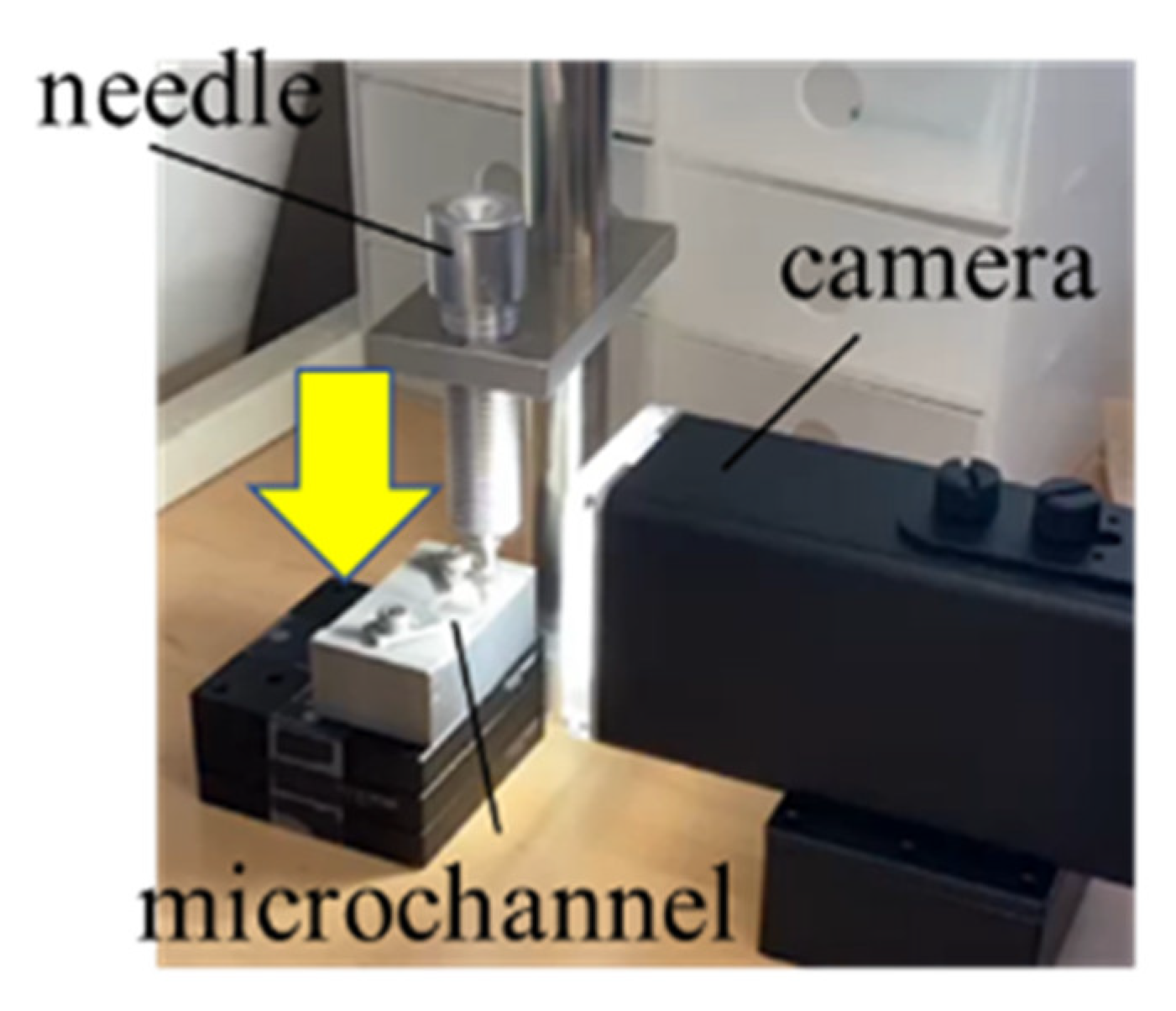
In order to investigate the on-off valve functionality in the fabricated microchannels, we visually observe the channel cross-sectional collapse when applying a load. Here, we find it necessary for the cured PDMS to exhibit low elastic modulus in order to completely close the flow lines. For a lower elastic modulus, we reduce the amount of initiator involved in the base monomer to 5:1 and 10:1 from the specified feed ratio of 1:1. The relationship between the on-off valve functionality and the elastic modulus (initiator feed ratio) is experimentally investigated using the apparatus shown in Figure 5.
Figure 6 shows photos of the cross-sectional shape of the pressurized microchannels. We confirm the that the channels are completely closed when pressure is uniformly applied across the cross section. The channels when monomer feed ratios are A:B = 5:1 and 10:1 require less load (only about 20% of the load required for 1:1) compared to that of 1:1, from which we find that the modulus of elasticity of the cured PDMS is lowered by reducing the amount of initiator included in KER-4690-B, and the channels can close with a lower pressure, as shown in Figure 6. However, by decreasing the initiator ratio, the monomer viscosity increases (KER-4690-A has higher viscosity than KER-4690-B), and the cross-sectional shape of the formed microchannels tends to deviate from a perfect circle. Furthermore, it takes longer to cure the PDMS monomer with a decrease of the initiator ratio. Therefore, a ratio between 3:1 and 5:1 is found to be optimal for fabrication.
Next, we investigate the minimum load required for complete closure of the channel with circular and non-circular cross-sections using the same apparatus shown in Figure 5. Then, it is confirmed that the channels with the circular and vertically long oval cross-sections require loads of 14.0 g and 52.8 g, respectively. In the case of oval cross-sections, the applied pressure is likely to disperse, and the effective load to close the channel tends to be lower. On the other hand, the load is uniformly applied to the channel with a circular cross-section, and therefore the channel can completely close even with a lower pressure. We also confirm that circular cross-sectional microchannels are closed with approximately one fourth of the pressure required for the channel with vertically long oval cross-section. Therefore, circular channels are more easily closed, which are experimentally verified by comparing with oval channels as it was theoretically expected in Ref. [1], although circular cross-section channels might not necessarily be the solitary candidate for on-off valves.

3.3. Redesigned Microchannels with On-Off Valves

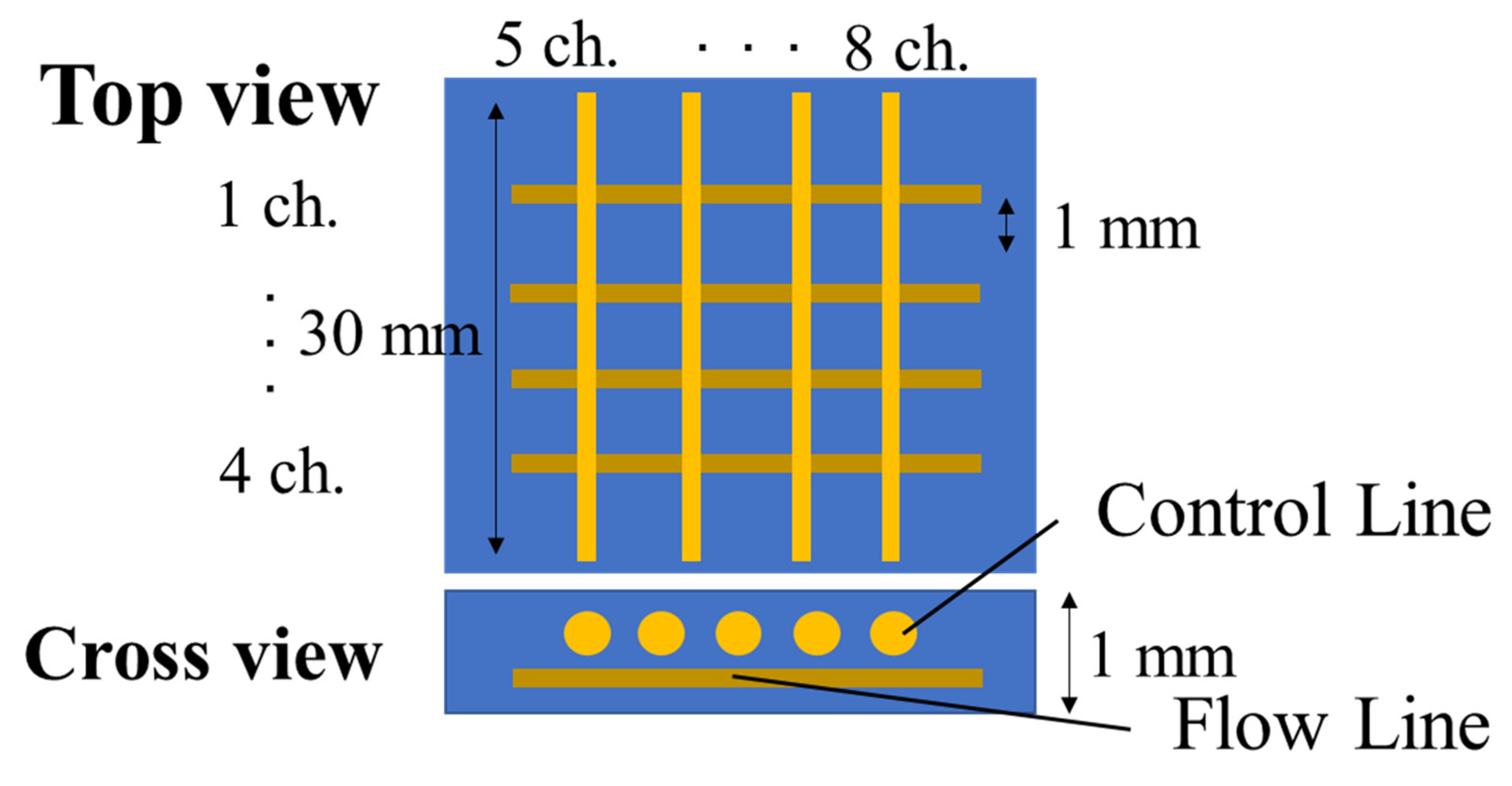
The ability to arrange channels three-dimensionally is one of the greatest advantages of the Mosquito method. Here, microchannels with a “3-D lattice” structure are designed and fabricated using a PDMS monomer with a low initiator feed ratio. In normal lattice structures, microchannels that are aligned on one plane must cross perpendicularly. In this microchannel, we would not be able to separate the flow and control lines. Therefore, the channels are formed on two separated layers: the lower layer channels are aligned in parallel to the x-axis, while the upper layer channels are in parallel to the y-axis. The upper and lower channels are utilized for the control and flow lines, respectively, as shown in Figure 7. They are designed such that the flow lines are nearby the inflated control lines.
Although we confirmed in Section 3.2 that the monomer feed ratio (A:B) should be 5:1, it influenced the monomer viscosity as well. When the viscosity of the PDMS monomer increased with less initiator, the channels’ cross-sections tended to be less circular. We also found in Section 3.1 that the polarity and viscosity of the silicone oil were also key for the cross-sectional shape. The designed 3-D lattice structure is formed by scanning the needle in the x- and 
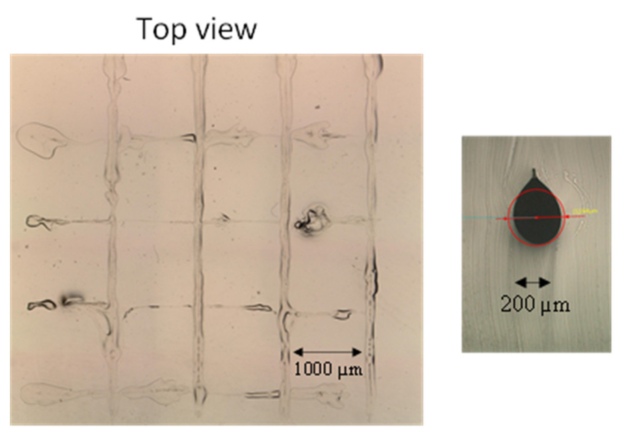
y-directions with different needle tip heights. When a monomer feed-ratio of A and B is set to 5:1 whilst KF-50 is dispensed, a top view of the fabricated 3-D lattice channels is shown in Figure 8. Although it is formed via the combination of A:B = 5:1 and KF-50, the structure is obviously distorted. To fabricate the 3-D lattice structure, the needle needs to scan in perpendicular directions for a longer time compared to the parallel monolayer structure. The viscosity of KF-50 is not high enough to maintain its cylindrical shape until the PDMS monomer is cured completely. In order to increase the curing speed, a feed ratio of A:B is set to 1:1 and 3:1. Top and cross-sectional views of the fabricated 3-D lattice channels are shown in Figure 9a,b, respectively. By increasing the feed ratio of the initiator, the structure tends to be stable, and the designed lattice structure is visually confirmed. Hence, a monomer feed ratio of 3:1 should be selected, although the modulus of elasticity slightly increases compared to that of 5:1. However, the cross-section of the channels shown in Figure 9b is not circular. The viscosity of KF-50 (3000 cP) is still low to maintain its circular cross-section under multi-directional monomer flow due to the two-layered needle scan. Therefore, in order to increase the viscosity of silicone oil, KF-96 (60,000 cP) is mixed with KF-50. Top and cross-sectional views of the fabricated 3-D lattice structure are in Figure 10a,b, respectively, using the mixed silicone oils with weight ratios of KF-50 and KF-96 are 1:2 and 1:1. Here, a monomer feed ratio (A:B) of 3:1 is fixed for PDMS. In both mixed ratios, 3-D structures without disconnection and distortion are visually confirmed, whilst a cross-section in Figure 10b is closer to a perfect circle than in Figure 10a. Hence, a mixed ratio of 1:1 should be selected for the silicone oil.
Finally, the different channel diameters are designed for the channels on the lower and upper layers: the upper layer for the control line should be larger than the lower layer in order to pressurize the flow line completely. Figure 11a,b are top and cross-sectional views of fabricated microchannels when the needle scan velocities for the lines of (flow, control) are set to (1, 2 mm/s) and (2, 4 mm/s), respectively. The channel diameter is theoretically estimated by Equation (1) derived from the Hagen–Poiseuille flow, based on the Naiver–Stokes Equation (2).
2 a = 2 Q π U = p d 4 32 U η L
Q = π d 4 p 128 η L
where U, p, d, L are the scan velocity, the dispensing pressure, the needle inner diameter, and the needle length, respectively.
From Equation (1), we find that the channel diameter is inversely proportional to the square-root of scan velocity. Since the scan velocity is twice as high for the lower layer channels, the channel diameter on the upper layer should be 1.4 times larger than that on the lower layer. Meanwhile, there is a concern that a higher scan velocity could disturb the channel arrangement due to the large monomer flow. Contrastingly, a higher scan velocity contributes to a shorter dispensing time for all the channels, which helps to maintain a cylindrical channel shape. Since silicone oil with a mixing ratio of 1:1 has both well-adjusted viscosity and polarity, higher scan velocities (2 and 4) mm/s can be selected for keeping the 3-D lattice structure with perfect circular cross-sections without deformation. From Figure 11a, the diameters of the upper and lower channels formed are measured as 299 μm and 199 μm, respectively. The control line on the upper layer has a 1.5 times larger diameter than that of the flow line on the lower layer, as expected. The heights of the upper and lower channels that are dispensed are 526 μm and 290 μm, respectively. Although the vertical channel spacing between them is designed to be larger than 200 μm, it is narrowed to 39 μm due to the different scanning velocities, as shown in Figure 11a. This vertical channel spacing is small enough to make them work as on-off valves.

3.4. Demonstration of Liquid-Flow

Finally, the channel closure experiment is conducted by actually flowing liquid into the fabricated microchannels with the “3-D lattice” structure to evaluate the functionality of the valve. Although several methods such as a micro vertically allocated SU-8 check valve or a microfabricated piston-less syringe pump to evaluate the valve performance have been reported, the method employed here utilizing the fluorescein solution is just an affordable method with our available equipment. For broader ranging analysis of the valve, we are willing to employ the other methods listed in the reviewer’s comment. In this setup, fluorescein water solution (1.0 × 10⁻² g/L) was injected into one of the flow lines, and the closure of the flow line was observed by detecting the fluorescence intensity from the fluorescein. The fluorescein solution liquid was injected into the flow line using a needle. Here, the needle outer diameter is 20 µm smaller than the channel diameter to provide a gap between them for the overflown solution when the flow line is closed. Meanwhile, nitrogen (N2) gas was injected into one control line, and the pressure varied from 0 to 300 kPa to inflate it and thus close the flow line. Top views of the intersections of the flow and control lines under different N2 gas flowing pressures are shown in Figure 12. In Figure 12, the flow line is aligned horizontally, as illustrated in Figure 7. Under a 0-kPa pressure in Figure 12, a high fluorescence intensity is observed from the intersection area marked with a red-coloured rectangle. However, the fluorescence intensity from the intersection decreases with the increase in N2 gas pressure. Hence, the liquid flow rate was reduced by the inflated control line.
Subsequently, we analysed these top-view images to quantitatively evaluate the change in fluorescence intensity. Figure 13 shows the number of pixels with respect to their brightness counted at the intersections in the red rectangle. When the fluorescent solution keeps flowing in the flow line under 0-kPa N2 gas, the number of bright pixels is high due to the large amount of flowing fluorescein. On the other hand, if the control line is inflated with a 100-kPa N2 pressure, the bright pixels decrease slightly, which is attributed to the fluorescein flow decrease. Then, with the increase in N2 pressure in the control line, dark pixels increased, as shown in the top view under 300 kPa in Figure 13, indicating a successful off-valve state. For comparison, two liquid flow rates, 1 and 5 µL/min were set to confirm that the valve could work under low flow rates. Even under higher flow rate (5 µL/min), the flow line can effectively be closed by inflating the control line under N2 gas pressure.
From Figure 14, the average number of bright pixels was statistically analysed, where the bright pixel number under no flow of N2 (0 kPa) was defined as a 100% intensity. Contrastingly, it decreased to 53.5% under 300-kPa N2 pressure as the minimum value. Meanwhile, if the peak number of bright pixels was analysed in the red rectangle, the intensity was found to decrease to 35.8% under 300-kPa N2 pressure. Regarding the fluorescence intensity as the volume of liquid flowing in the flow line, 300-kPa N2 pressure to the control can block approximately 40–50% of the flow volume independent of the liquid flow rate, confirming the capability of the 3-D lattice microchannels as an on-off valve.

4. Conclusions

We proposed microchannels with on-off valve functionality to precisely control the amount of chemicals to be supplied to reactors. In this paper, we focused on microchannels with a circular cross-section with an ability to constrict the flow line and completely block the liquid flow in it by side pressure to realise a high-precision on-off valve. We applied the Mosquito method to fabricate the circular cross-sectional microchannels. The Mosquito method was originally developed as a fabrication method for polymer optical waveguides.
Next, it was confirmed that a low elastic modulus of PDMS used as the microchannel material largely contributed to closing the channel with a lower pressure. Furthermore, compared to vertically oval cross-sectional channels, circular cross-section microchannels could play the role of on-off valves because the load is applied uniformly to the flow channel.
Finally, fluorescein solution was flown into the fabricated channels with a “3-D lattice” structure, and we found that the fluorescence intensity decreased (Video S1) just at the intersection between the flow and control lines with an increase in N2 pressure to inflate it, from which the valve functionality of microchannels fabricated by the Mosquito method is experimentally confirmed.

Supplementary Materials

The following supporting information can be downloaded at: https://www.mdpi.com/article/10.3390/micro3030043/s1, Video S1: The fluorescence intensity decreases at two liquid flow rates, 1 and 5 µL/min.

Author Contributions

Conceptualization, Y.H. and T.I.; methodology, K.U.; validation, K.U., Y.H. and T.I.; data curation, K.U.; writing—original draft preparation, K.U.; writing—review and editing, T.I.; supervision, Y.H. and T.I.; project administration, T.I.; funding acquisition, T.I. All authors have read and agreed to the published version of the manuscript.

Funding

This research received no external funding.

Institutional Review Board Statement

Not applicable.

Informed Consent Statement

Not applicable.

Conflicts of Interest

The authors declare no conflict of interest. This section is not mandatory but may be added if there are patents resulting from the work reported in this manuscript.

References

  1. Gibson, D.G.; Glass, J.I.; Lartigue, C.; Noskov, V.N.; Chuang, R.-Y.; Algire, M.A.; Benders, G.A.; Montague, M.G.; Ma, L.; Moodie, M.M.; et al. Creation of a Bacterial Cell Controlled by a Chemically Synthesized Genome. Science 2010, 329, 52–56. [Google Scholar] [CrossRef] [PubMed] [Green Version]
  2. Ohga, K.; Ishigure, T. Fabrication for polymer microchannels with circular cross-sections for bio-chip applications. In Proceedings of the 2016 IEEE CPMT Symposium Japan (ICSJ), Kyoto, Japan, 7–9 November 2016; pp. 95–98. [Google Scholar] [CrossRef]
  3. Au, A.K.; Lai, H.; Utela, B.R.; Folch, A. Microvalves and Micropumps for BioMEMS. Micromachines 2011, 2, 179–220. [Google Scholar] [CrossRef] [Green Version]
  4. Ito, M.; Sugiura, H.; Ayukawa, S.; Kiga, D.; Takinoue, M. A Bacterial Continuous Culture System Based on a Microfluidic Droplet Open Reactor. Anal. Sci. 2016, 32, 61–66. [Google Scholar] [CrossRef] [PubMed] [Green Version]
  5. Nakazawa, R.; Ishigure, T. Fabrication for polymer microchannels with circular cross-section using photo-curable PDMS. In Proceedings of the 2019 IEEE CPMT Symposium Japan (ICSJ), Kyoto, Japan, 18–20 November 2019. [Google Scholar] [CrossRef]
  6. Lima, R.; Wada, S.; Tanaka, S.; Takeda, M.; Ishikawa, T.; Tsubota, K.; Imai, Y.; Yamaguchi, T. In vitro blood flow in a rectangular PDMS microchannel: Experimental observations using a confocal micro-PIV system. Biomed. Microdevices 2007, 10, 153–167. [Google Scholar] [CrossRef] [PubMed] [Green Version]
  7. Unger, M.A.; Chou, H.-P.; Thorsen, T.; Scherer, A.; Quake, S.R. Monolithic Microfabricated Valves and Pumps by Multilayer Soft Lithography. Science 2000, 288, 113–116. [Google Scholar] [CrossRef] [PubMed] [Green Version]
  8. Chen, Y.; Li, Y.; Li, D.; Li, J.; Chen, H. Margination mechanism of stiffened red blood cell in microchannel with different cross-section shapes. Microfluids Nanofluids 2019, 23, 25. [Google Scholar] [CrossRef]
  9. He, R.; Yunus, D.; Uhl, C.; Shi, W.; Sohrabi, S.; Liu, Y. Fabrication of circular microfluidic channels through grayscale dual-projection lithography. Microfluids Nanofluids 2017, 21, 13. [Google Scholar] [CrossRef]
  10. Wang, G.-J.; Ho, K.-H.; Hsu, S.-H.; Wang, K.-P. Microvessel scaffold with circular microchannels by photoresist melting. Biomed. Microdevices 2007, 9, 657–663. [Google Scholar] [CrossRef] [PubMed]
  11. Hatai, R.; Hama, H.; Ishigure, T. Fabrication for single/few-mode Y-branch waveguide using the Mosquito method. Opt. Express 2022, 30, 3524. [Google Scholar] [CrossRef] [PubMed]
  12. Rasel, O.F.; Ishigure, T. Circular core single-mode 3-dimensional crossover polymer waveguides fabricated with the Mosquito method. Opt. Express 2019, 27, 32465–32479. [Google Scholar] [CrossRef] [PubMed]
Figure 1. If no pressure is applied to the control line, chemical reactions occur and the product concentration could increase. On the other hand, when pressure is applied to the control line, the control line is inflated, causing the flow line to be squeezed, and then, the liquid is blocked [5].
Micro 03 00043 g001
Figure 2. When applying pressure to a channel, the calculations show that the channel with a rectangular cross-section may not close because the pressure is not uniformly applied to the flow line. On the other hand, when pressure is applied to a circular cross-section, it is very likely to close because the pressure is applied uniformly to the flow line, as calculated in Ref. [1].
Micro 03 00043 g002
Figure 3. Circular cross-section microchannels were fabricated by applying the Mosquito method which was invented to fabricate polymer optical waveguides with circular cross-sectional cores. (a) Coating; (b) Dispensing; (c) Curing; (d) Removal of chanel pattern material.
Micro 03 00043 g003
Figure 4. Circular cross-section microchannels can be fabricated using silicone oil (a) KF-96 with vertically long oval (b) KF-50 with perfect circle due to the difference of polarity with the PDMS monomer.
Micro 03 00043 g004
Figure 5. To observe the cross-sectional shape of the fabricated microchannels when pressurized from the perimeter, a load is applied to a channel from the top surface using a needle. This self-made tool can apply a load similar to a hardness gauge.
Micro 03 00043 g005
Figure 6. We find that by reducing the modulus of elasticity of the cured PDMS, channels could close with a lower pressure. Required loads to completely close a channel are (a) 79.0 g for A:B = 1:1 (b) 14.0 g for A:B = 5:1 and (c) 14.5 g for A:B = 10:1.
Micro 03 00043 g006
Figure 7. We design microchannels with a “3-D lattice” structure for on-off valves.
Micro 03 00043 g007
Figure 8. We find that the fabricated channels are largely distorted when using the combination of monomers A:B = 5:1 and KF-50.
Micro 03 00043 g008
Figure 9. By reducing the amount of initiator in PDMS monomers, the reproducibility greatly improves (a) A:B = 1:1, (b) A:B = 3:1.
Micro 03 00043 g009
Figure 10. The mixed silicone oil with a weight ratio of KF-50:KF-96 = 1:1 makes the cross-sectional shape perfectly circular (a) KF-50:KF-96 = 1:2, (b) KF-50:KF-96 = 1:1.
Micro 03 00043 g010
Figure 11. Since KF-50 has an appropriate polarity difference compared to PDMS monomer and KF-96 has a high viscosity, their mixture enables the stabilization of the channel patterns without disconnection or distortion. Scan velocities for the layers of (lower and upper) are (a) (1, 2) mm/s, (b) (2, 4) mm/s.
Micro 03 00043 g011
Figure 12. The fluorescence intensity decreases just at the intersection when varying the load to be applied from 0 kPa to 300 kPa.
Micro 03 00043 g012
Figure 13. Two liquid flow rates are examined for comparison. It was found that the flow line was effectively closed by adding pressure even under higher flow rate. Supplemental motion pictures visualise the valve functionality more clearly.
Micro 03 00043 g013
Figure 14. In both analysis conditions (peak and the average number of pixels), a pressure of 300 kPa can reduce about 40–50% of the flow volume.
Micro 03 00043 g014
Disclaimer/Publisher’s Note: The statements, opinions and data contained in all publications are solely those of the individual author(s) and contributor(s) and not of MDPI and/or the editor(s). MDPI and/or the editor(s) disclaim responsibility for any injury to people or property resulting from any ideas, methods, instructions or products referred to in the content.

