1. Introduction
As highway infrastructure ages and requires regular maintenance to meet today’s needs, temporary work zones are increasingly necessary to upgrade deteriorating transportation infrastructure [
1]. Work zones may be hazardous to the traveling public and workers because they disrupt traffic patterns and roadway layouts [
2]. In fact, the U.S. experiences over 700 fatalities and nearly 37,000 injuries each year in temporary construction and maintenance work zones [
3,
4]. In Virginia alone, the number of fatal work zone crashes increased from 7 fatal crashes in 2015 to 17 in 2019, almost double the 2015 record [
5]. Hence, measures such as effective work zone management are essential steps to mitigate roadway accidents.
Because effective work zone management requires a careful balance of safety and mobility, attenuators—also known as crash cushions or energy absorption cartridges—play a major role in ensuring the safety of road users. Truck-mounted attenuators (TMAs) are designed to improve mobile work zone safety by shadowing the work truck, enhancing work zone visibility, and capturing drivers’ attention to facilitate merging into a work-free lane early and safely [
6]. TMAs are mobile since they are attached to the rear of a work truck, which provides protection to the work crews and traveling public from the severe consequences of rear-end crashes between motorists and slow-moving or stationary work vehicles [
7].
Despite the use of TMAs and other precautions—such as shadow vehicles, arrow boards, and signs to preemptively warn drivers of a mobile work zone—some drivers do not respond to warnings, and eventually collide with the TMA [
8]. When investigating the frequency of crashes involving TMAs in Virginia work zones from 2011–2014, Cottrell [
9] found that 63% of TMA crashes occurred during the day, 25% happened in darkness on lighted urban interstate roads, 9% took place in darkness on unlighted roads, 2% at dawn and 1% at dusk. Such data demonstrate a critical need to advance current practices related to vehicle conspicuity, traffic control devices, changeable message signs (CMSs), location staging, and the configuration of work zones to reduce the rate of injuries and fatalities during road construction and maintenance activities.
To address this concern, this study conducted a state-of-the-art review to identify demonstrated countermeasures that reduce truck-mounted attenuator crashes by improving the visibility of TMAs, enhancing work zone configurations, and safeguarding construction personnel and vehicle operators in the work area. This manuscript first discusses the types of attenuators and their recommended applications. Second, it addresses different traffic control devices that may be used to improve the safety of workers and operators. Third, this paper examines warning lights and chevron markings that may be utilized to improve the visibility of TMAs. Then, work zone configurations and variables that should be considered during deployment of TMAs are presented. Training for work zone personnel and seatbelt systems for operator safety are reviewed. Lastly, intelligent transport systems that may be applied to enhance the smart recognition of TMAs arepresented. Overall, this study identifies potentially beneficial mitigation strategies that enhance work zone safety during the execution of road construction projects.
2. Method: Literature Search and Analysis
In the current study, a literature review was carried out for research that investigated methods of enhancing TMA visibility, improving work zone configurations, and ensuring worker safety in construction work zones. Keywords, titles, and abstracts were manually searched in major commercial bibliographic databases of work published between the years 1990 and 2020. These databases included the American Society of Civil Engineers (ASCE) library, Science Direct, Wiley Online Library, Taylor and Francis Online, Frontiers in Built Environment, Sage Publications, Academia, Emerald and Research Gate. To identify relevant previous studies for a comprehensive review, the research keywords included “truck-mounted attenuator visibility”, “work zone protection”, “rear-end crashes”, “vehicle intrusion”, “work zone personnel safety” and “vehicle operator safety”. Additionally, the reference list of all downloaded papers was searched for relevant articles not captured in the manual inspection. At the end of the search in the databases and reference lists, a total of 189 papers and reports were downloaded. Thereafter, each title and abstract were reviewed, and those identified as relevant to the study were selected for further examination. Studies were chosen based on the following inclusion criteria: (a) the study included relevant factors that impact the safety of construction work zones; (b) the research was published no earlier than the year 1990 (between 1990 and 2022); (c) the study was available online; (d) the study was published in a refereed journal; and (f) the study was written in the English language.
For this review, 126 abstracts satisfied the inclusion criteria, and after a complete study of the publications, a total of 84 scholarly articles provided data beneficial toward achieving the objectives of the study, particularly with variables that enhance TMA visibility and improve the safety of construction work zones. The distribution of scholarly articles utilized in this study according to the year of publication is as follows: 1991 to 2000 (6%), 2001 to 2010 (31%), and 2011 to 2022 (63%).
A structured data extraction form was generated before commencing the review and was utilized to extract data from each study. The papers were reviewed and evaluated based on study design, data collection approach, analytical methods, key findings, and significance of research toward ensuring TMA visibility and improving work zone safety. Several safety variables were identified, condensed according to common themes, and grouped under seven categories. Thereafter, a framework for the study was designed and developed as displayed in
Figure 1.
3. Types of Attenuators
Three types of attenuators were identified and analyzed by the Missouri Department of Transportation [
10]: TMAs, TTMAs and freestanding impact attenuators (sand barrels). The impact attenuators provide safety for a passenger by absorbing impact energy. They also safeguard the work zone from intruding vehicles and serve as a platform to disseminate information to other road users via warning signs. The ability of an operator to effectively position the support vehicle or attenuator is essential to the safety of workers and the work zone. It is also vital to provide ample roll-ahead distance for the attenuators in the event of a crash and visible warning signs to road users. The pros and cons of utilizing TMAs and TTMAs are summarized in
Table 1.
Most state highway agencies recommend the use of a TMA for mobile work zones. The guidelines for the shadow vehicles and TMAs are summarized in
Table 2. The Virginia Department of Transportation (VDOT) and Virginia Work Area Protection Manual (VAWAPM) recommend the use of shadow trucks with a TMA in the following situations: (a) lane closure on roadways with more than three lanes and a posted speed limit of 45 mph or higher; (b) on shoulders, ramps, and loops of interstate highways and those with restricted entry; (c) on roadways with a posted speed limit of 45 mph or greater where mobile operations are conducted on multiple lanes; and (d) other locations where protection is required at the discretion of the regional traffic engineer [
9]. This way, the shadow TMA provides visible guidance and warning signs that alert motorists about maintenance activities in advance and prompt them to slow down to the specified speed limit as they drive past the work zone.
As shown in
Table 2, most work zones require TMA protection. Many state highway agencies have established recommendations to guide work vehicle drivers in mobile work zones and require them to use a TMA for moving lane closures. However, TMA use in some states, such as Delaware, is statutory [
12]. TMAs are also reported to have a positive benefit–cost ratio: An early study [
11] recorded injury and damage savings of USD 23,000 per TMA crash, as stated in a report for the Texas legislature. Additionally, Ullman and Iragavarapu [
7] utilized the work zone crash database of the New York State Department of Transportation to evaluate a achieve savings of USD 196,855 in crash costs when a TMA was used versus when it was unutilized not used. It was confirmed that agencies could recoup the capital expended on the purchase of a TMA in one year of daytime work shifts for facilities serving 20,000 vehicles or more per day, and in one year of nighttime work shifts for facilities handling above 50,000 vehicles per day.
4. Traffic Control Devices to Reduce TMA Crashes
Traffic control devices are visual countermeasures that communicate relevant work zone information to drivers. In mobile work zones, traffic control devices guide motorists through the work zone using shadow vehicles, arrow boards and signs to alert drivers of imminent mobile work zones [
8]. Despite the use of these control devices, work zone crashes remain at worrisome levels due to factors emanating from the complexity of traffic in these work zones [
13]. Furthermore, the outcome of a field study [
14] observed that drivers’ misunderstandings of traffic control devices, motorists intruding into the work fleet, the speed differential between traffic and the work fleet, and the visibility of work vehicles were the major hazards in mobile work zones. The study also found that warning signs not properly maintained may become illegible, worn out, or non-retroreflective, thereby posing significant hazards to the traveling public and workers in these work zones. Thus, it is important to maintain these devices in order to retain their visibility and functionality in guiding motorists safely through the work zone.
A comprehensive literature review revealed that using traffic control devices such as portable changeable message signs (PCMS) and static signs, variable speed limit signs (VSLS), positive protection devices, police cars, work vehicles with TMAs, vertical and horizontal deflections, alarm devices, directional audio systems (DASs), retroreflective tapes, and personal protective equipment (PPE) could result in lower incidents involving TMAs. The salient findings from past research related to these traffic control devices are summarized.
4.1. Portable Changeable Message Signs (PCMS) and Static Signs
Message signs convey relevant information to motorists regarding imminent work zones to improve driver behavior, traffic flow, safety and maintenance operations [
1]. A truck equipped with PCMS, variable message signs (VMS), or dynamic message signs (DMS) are usually preferred to static signs due to their ability to clearly convey information to drivers at a far distance from a mobile work zone. Typically, PCMSs are limited to three lines with eight characters resulting in a maximum message size of twenty-four characters [
15]. The height of a character may vary from 18 to 54 inches and should measure five pixels wide by seven pixels high at a minimum [
16]. One study [
17] tested PCMS messages on an advance warning truck for a rural site on I-88 to assess their effect on drivers’ speeds at the work area, observing that a single ‘
Right Lane Closed’ message as well as alternating ‘
Right Lane Closed’ and ‘
Reduce Speed’ messages produced average speeds of about 62 mph (when the posted speed limit was 65 mph). Alternating ‘
Right Lane Closed’ and ‘
Reduce Speed 45 MPH’ messages produced approximately a 5-mph speed reduction (from 62 mph to 57 mph).
In addition, research recommends that advance warning signs be posted about 400 m (1312 ft) upstream of the TMA and shadow vehicle [
3].
The Manual on Uniform Traffic Control Devices (MUTCD) also requires that a driver reads the VMS at least twice while moving at the specified speed limit. Therefore, a VMS should be strategically placed to display relevant work zone information and call the attention of a driver to the appropriate line of action in a timely manner to ensure the safety of maintenance workers and the traveling public.
4.2. Variable Speed Limit Signs (VSLS)
VSLSs are electronic devices that display posted speed limits and are manipulable by an operator as required. VSLSs serve as an alternative to speed limit signs and convey the required speed with respect to such environmental conditions as congestion, construction activity, inclement weather and crashes [
18]. VSLS also improve driver speed compliance and reduce speed differentials, subsequently reducing the potential for crashes over time [
19,
20,
21].
4.3. Positive Protection Devices
The Federal Highway Administration [
22] defines positive protection as equipment used to contain and redirect vehicles to prevent them from intruding a work zone. Positive protection devices create a divide between traffic and work activities, shield workers from motorists, and reduce the potential for a fatal crash between motorists and workers in the work zone [
3]. Some of the conventional positive protection devices used in work zones include portable concrete barriers with end-crash cushions, sand- or water-filled barriers, truck-mounted attenuators and vehicle arresting systems.
4.4. Police Car
The presence of police around the work zone is an effective speed control measure for the traveling public. Police presence had a positive effect on speed reduction, as evaluated in an early study [
17]. Without police presence, traffic flowed freely at speeds of 50 to 60 mph on a road with a speed limit of 45 mph. However, speeds decreased by about 10 to 15 mph when a police car with revolving lights was positioned in the work zone, which resulted in heavy congestion. No vehicle entered the TMA taper when a police car was present.
4.5. Work Vehicles with TMAs
TMAs are designed to shadow the work vehicle and provide visible guidance to attract the attention of motorists in advance and prompt them to reduce their speed as they navigate the work zone. Because some vehicles may intrude the work zone due to inattention, a work vehicle secured with a TMA helps to absorb the crash impact of an errant vehicle.
4.6. Vertical and Horizontal Deflections
Vertical deflections—such as speed bumps, or humps, and cushions—and horizontal deflections—including pinch points, central hatching, traffic islands, and roundabouts—significantly reduce the potential for crashes that may result in major injuries and worker fatalities in low-speed work zones [
2,
23]. These deflections are effective for controlling vehicle speeds and improving the safety of pedestrians, particularly in residential areas.
4.7. Alarm Device and Directional Audio System (DAS)
An alarm device is attached to the TMA-equipped work vehicle and is followed by a shadow vehicle on the shoulder of a roadway work zone. The alarm device is a dual system warning device that includes lights and sounds when triggered by motorists approaching the work vehicle without changing lanes at the required cut-out distance. The DAS—consisting of parametric speaker arrays and a long-range acoustic device—is a warning device that produces a distinctive warning sound that surpasses background or road noise, in contrast to the alarm system [
6]. Deciding which system to use involves trade-offs among many factors, such as performance, cost, maintenance requirements, and ease of operation. The DAS is more expensive than the alarm device due to the cost of the DAS unit and actuation device, which require significant energy to operate. However, DAS units provide a more continuous and relatively uninterrupted operation than an alarm system [
6].
4.8. Retroreflective Tapes and Personal Protective Equipment (PPE)
Since work zone operations are usually obtrusive to the flow of traffic, it is important that work vehicles and equipment deployed within the work zones are highly visible to motorists. Lights and retroreflective tape enhance visibility and alert motorists to potentially hazardous situations [
24]. Retroreflective tape is recommended for use with flashing warning lights to highlight vehicle shape and increase vehicle conspicuity. However, it should not be used alone or in place of flashing lights on work vehicles [
3,
24]. Particularly, the Virginia Department of Transportation requires workers within the right of way and exposed to traffic to wear ANSI Class 3 high-visibility vests during both daytime and nighttime operations. Such apparels are required to have an outer material color of fluorescent orange–red, fluorescent yellow–green, or a combination of these, and should be visible at a minimum distance of 1000 feet. Likewise, headwear with a minimum of 10 square inches of retroreflective material visible on at least three sides of the hat (as defined in the ANSI/ISEA 107-2010 standards) are also required.
Similarly, the fluorescent prismatic lens type of retroreflective sheeting should be utilized as traffic signs, capable of retroreflecting at entrance angles of about 50 degrees with observation angles of 0.2 and 0.5 degrees to ensure the safe movement of traffic on highways during nighttime conditions. Such visibility markers aid drivers in identifying work zones and workers with sufficient time to enable caution.
5. Warning Lights
Warning lights are mounted on TMAs for reasons pertaining to safety during travel. These include cautioning motorists of maintenance vehicle activities on a road or near the roadway, notifying drivers to react in advance, defining the shape and size of work vehicles, and conveying the intent of the TMA [
25]. Warning lights are powerful tools that communicate the urgency of a potentially dangerous situation ahead, enabling motorists to anticipate danger with adequate time to avoid inadvertent intrusions into work zones during the day or night. After conducting a comprehensive literature review on warning lights, the authors summarized the results into four main topics: types of warning lights; colors of warning lights; research on warning lights; and selecting features of warning lights.
5.1. Types of Warning Lights
Different types of lights have been used by highway construction and maintenance workers. Trench et al. [
26], on behalf of the Federal Emergency Management Agency, summarized the major types of lights used on emergency vehicles in the U.S.:
Rotating Lights: These lights are among the earliest kinds of warning lights employed for use on emergency vehicles. An attraction for the use of the rotating light is the flashing effect that it generates when the beacon revolves within its casing, thus capturing the attention of motorists. Rotating lights illuminate the entire area surrounding the vehicle on which they are attached.
Fixed Flashing Lights: The beam of the fixed flashing light is unidirectionally projected and warns motorists when it flashes on and off. Usually, they are utilized as auxiliary lighting on the lower parts of a vehicle to amplify the main lighting system structured above the vehicle.
Strobe Lights: These lights were the first new additions to emergency vehicle lighting capabilities following the era of rotating lights. Strobes are fixed lights that flash in one direction. Rotating lights or strobe lights provide a close substitute for flashing warning beacons when performing maintenance operations during the daytime as these lights may provide similar functions on a maintenance vehicle [
22].
Light-emitting Diodes (LEDs): LEDs have a remarkably long lifespan and project a strong ray of light with a reduced amount of electrical energy in contrast with the flashing and strobe lights. This feature has the advantage of preserving the vehicle’s electrical system in addition to their outstanding illumination and high level of visibility.
The FHWA [
22] identified four categories of 360-degree warning lights as itemized in
Table 3.
5.2. Colors of Warning Lights
The colors of warning lights used on specific types of service vehicles are generally regulated by state motor vehicle codes (e.g., 46.2-1025 (Virginia); 32-5-241 (Alabama); 547.105 (Texas)). Five common colors of warning lights used by state DOT personnel are summarized [
26]:
Red Lights: Typically, service vehicles not utilized for emergency purposes are barred from displaying red flashing lights. They are important since motorists are required by motor vehicle codes to yield or come to a complete stop for vehicles that have red warning lights in operation.
Amber (or Yellow) Lights: In contrast to red lights, these lights are designed as cautionary warning lights and do not require a yield or complete stop by motorists when in operation. They are frequently utilized on construction vehicles and have the widest spectrum of acceptable use in most motor vehicle codes.
White Lights: White lights function as a contrasting color when used together with other light colors on emergency vehicles.
Green Lights: Some states use the green lights on private security guard vehicles, privately owned vehicles by emergency medical service (EMS) personnel or volunteer firefighter vehicles. They are also employed to indicate the position of an incident command post.
Blue Lights: In the United States, blue lights have the broadest variety of use on tow trucks, snowplows and other public utility vehicles. In addition, many states use them as a contrasting color with the red light and other light colors on emergency vehicles.
5.3. Research on Warning Lights
Various studies have investigated the use of warning lights with respect to the peculiarity of conditions that exist in each region [
8,
25,
27,
28,
29,
30]. The salient results of these studies (sorted according to location) are summarized here.
Kentucky [
28]: Kentucky Transportation Center (KTC) conducted two external surveys to assess warning light products and practices within the U.S. The study found that most DOTs use an amber color and LED sources for their warning lights. Additionally, majority (>75%) of the reporting agencies placed warning lights on the roofs of highway work vehicles to maximize visibility to motorists. The study recommended the use of amber and white colors for KTC work vehicles, an asynchronous flashing pattern with slow flash frequencies and LED bulbs. In addition, the study suggested that warning lights be placed at high elevations on the vehicle against a solid-colored background that contrasts with the sky.
Minnesota [
27]: MnDOT evaluated eight lighting configurations to determine effective lighting options to slow moving vehicles and steer them away from workers in the work zone. One problem the study sought to address was developing an alternative to the traditional incandescent amber double rotator warning lights on maintenance vehicles. Researchers observed that these lights did not effectively alter driver behavior nor create a safer work environment for workers in the right of way. The evaluation showed that LED lights were brighter than the incandescent double rotator at distances from 250 to 3000 feet, thus making warning lights more effective. Furthermore, the use of full-width warning light bars, addition of blue lights into the warning light configuration, and inclusion of extra lower lights were found effective in alerting drivers to move to the left lane and maneuver away from the work zone.
Missouri [
10]: MoDOT developed fleet lighting guidelines to establish an adequate minimum level of warning lighting on MoDOT equipment in addition to recommendations from manufacturers. These guidelines were intended to increase the visibility of vehicles and enhance the safety of workers and the traveling public. The warning light guidelines for specific MoDOT vehicles are outlined in
Table 4, showing that the fleet lighting level increases with the level of exposure.
Another study by Brown et al. [
8] on behalf of MoDOT investigated the use of green versus traditional amber lights on TMAs to examine whether their use could improve safety in mobile work zones. Amber/white, green only, green/white, and green/amber color configurations were evaluated via a combination of simulator and field studies. The amber/white combination achieved the highest work zone visibility in the simulator study but generated the greatest level of unease with disability glare. In contrast, the green-only configuration produced a low overall visibility but with the advantage of a minimum disability glare. Both results implied an inverse relationship between the visibility of the work zone and arrow board recognition. A summary of the research findings is presented in
Table 5.
Texas [
29]: To increase the visibility of maintenance vehicles to the traveling public, the Texas Transportation Code categorizes vehicles by type and defined standards and specifications for warning light requirements for various maintenance, emergency, or service vehicles. Highway maintenance or construction vehicles utilizeflashing amber lights but are prohibited from operating flashing white lights. Moreover, conditions are specified for the use of simultaneous amber and blue warning lights, such as during snow removal, continuous or intermittent mobile operations with a stoppage time of approximately 15 min, while working beside moving traffic or the shoulder edge without supporting channeling devices, and in response to incidents. It was recommended that blue and amber lights be set up to independently operate. The installation of the blue warning light was suggested on the driver’s side to enhance visibility.
Virginia [
31]: VDOT requires amber high-intensity rotating, oscillating, or flashing lights to be used on vehicles performing moving and mobile operations or entering and exiting the work zone at night. More so, lights should be mounted for a 360-degree view and visible for 1/2 mile on limited access highways and 1500 feet on all other roadways.
New Zealand [
25]: Outside the United States, research was conducted by Smith et al. [
25] to evaluate the visual performance of TMAs under clear weather driving conditions on New Zealand roads. The study found that 340 mm diameter flashing strobe lights increased the visibility of the TMA, out-performed rotating beacons, and resulted in quicker responses from drivers. The study recommended that lights be mounted high above the arrow board and advance warning system. The warning lights should be operated in an asynchronous pattern when the arrow board lights are not in use to avoid conflicting with the visual performance of the warning signs. Wide retroreflective tape around the edges of the arrow board was discovered significant in improving the average distance at which drivers recognized the TMA: by at least 125 feet. In summary, the study revealed that: (1) an all-amber light bar system with rotating elements was effective for mobile operations; (2) a combination of rotating beacons with flashing strobe lights was effective in both mobile and stationary operations; and (3) a combination of blue and amber rotating beacons, compared to amber lights only, resulted in a significant speed reduction.
On average, these findings suggest that most DOTs recommend the use of amber and white warning light colors for work zone visibility and identified the best performance from LED bulbs flashing in an asynchronous pattern that does not conflict with the arrow board lights nor impair the visual performance of the warning signs. The inclusion of blue lights in the warning light configuration was also supported, particularly when installed on the driver’s side to enhance visibility. The configurations are effective in encouraging the traveling public to move to the appropriate lane and away from the work zone within the shortest time possible. Lights are recommended to be mounted at high elevations on the vehicle against a solid-colored background that contrasts with the sky. Factors to be considered when selecting the appropriate warning lights are discussed next.
5.4. Selecting Features of Warning Lights
The selection of warning lights based on a combination of features can improve work zone visibility and ultimately the safety of workers and road users. Some characteristics are highlighted below:
Color: Since the sensitivity of human vision varies across colors, the color of lights is an important consideration in TMA light bar configuration [
8].
Table 6 shows that most DOTs select amber-colored warning lights used either exclusively or with other colors. However, a study by MnDOT on the use of equipment lighting during snowplow operations observed that operators preferred white-colored warning lights due to increased conspicuity during low visibility conditions [
32].
Light Source: Light sources affect the intensity of warning lights. Most light signals used for warnings are simple flashing units such as halogen lights, xenon strobes, or LEDs [
33]. Modern flashing LED lights were found brighter than conventional incandescent or halogen strobes. A study carried out by MnDOT [
27] observed that LED lights were far brighter than incandescent double rotators at distances of 250 to 3000 feet from the maintenance vehicle. LED light sources were also favored for use in new vehicles, retrofits and replacements due to improved visibility, energy efficiency and long service life [
32].
Flash Requirements: The American Association of State Highway and Transportation Officials (AASHTO) suggests the use of an asynchronous flashing pattern with slow flash frequencies to accomplish a satisfactory motorist response. They note that a flash rate of 1 Hz alerts motorists faster than the 4 Hz alternative [
34]. Additionally, these flashing lights are more conspicuous and provide a greater sense of urgency than a steady burning light of equivalent intensity [
24].
Positioning: Placing a warning light on a highway vehicle can improve safety performance by enhancing a vehicle’s visibility to motorists approaching a work zone [
28]. For maximum results, as recommended by AASHTO [
34], the use of a lighting system visible from 360 degrees such as a rotating beacon placed on top of the vehicle or a setup of separate lights on each side of a vehicle will provide a satisfactory view from a driver’s angle of approach. Muthumani et al. [
32] observed that lights mounted at a height near a driver’s line of sight tend to increase glare especially at close distances. Therefore, lights should be positioned at a remarkably high elevation on the vehicle to minimize the likelihood of visual impairment. Moreover, specialty vehicles used in mobile operations should have a 360-degree coverage with self-contained LED units using mounting specifics dictated by the vehicle’s physical characteristics [
27].
Contrast: Warning lights should provide a suitable contrast with the surroundings to allow motorists readily identify them. Gibbons et al. [
24] recommend warning lights be positioned against a solid-colored background to contrast with the sky and maximize visibility.
Conspicuity: Conspicuity is the ability of a vehicle to draw attention to its presence even when other road users are not actively looking for it [
35]. The use of warning lights is the predominant method used to increase work vehicle conspicuity. Beyond attracting drivers’ attention, the goal of conspicuity is to provide drivers with information about a vehicle’s presence, size, position, speed and direction of travel [
26].
Intensity: Warning lights should be conveniently visible during both day and nighttime without excessive glare or distraction [
33]. Glare is caused by a bright light source in a person’s field of view, significantly reducing the ability to view other objects. Trench et al. [
26] distinguished between two types of glare:
Disability glare occurs when a driver is unable to identify potential hazards on the road as a result of temporary blindness despite viewing them directly.
Discomfort glare causes motorists to turn away their eyes from a beam of light, leading to failure to detect obstacles soon enough to avoid them.
Distinct light intensity ranges are required for daytime and nighttime conditions. While higher minimum thresholds are essential for lights to provide a prominent view against the brightness of the sky during the day, lower maximum thresholds are necessary to prevent an advancing motorist from encountering intrusive glare conditions during nighttime [
28]. Therefore, a balance between vehicle conspicuity and light intensities should be achieved to allow motorists identify potential hazards with sufficient time to take early avoidance action. To this end, AASHTO provides recommendations for daytime and nighttime lighting intensities according to light sources as shown in
Table 7.
Retroreflectivity: Retroreflective tape markings (e.g., reflective red–silver adhesive tape) are effective in providing an additional level of warning for approaching vehicles. Although of limited benefit during the day, correctly applied and maintained retroreflective sheeting materials can significantly increase nighttime visibility and conspicuity of work vehicles [
22].
External light sources enhance the retroreflective properties of materials. Moreover, the degree to which a maintenance vehicle with retroreflective striping reflects light toward its origin is contingent on the amount of incoming light hitting the retroreflective surface and the specific viewing geometry of motorists [
26]. Smith [
25] suggests that arrow boards be fitted with wide retroreflective tape around their edges. Attaching these strips enhances the shape and size of the TMA, provides critical information to motorists and improves visibility for navigation during night conditions.
Table 8 provides a summary of the recommendations for warning lights on TMAs.
6. Chevron Markings
Chevron panels are made from high-quality prismatic reflective sheeting, which adds an additional layer of safety by increasing the conspicuity of maintenance vehicles. The sheeting usually combines a base and contrasting color in alternating inverted ‘V’ stripes or checkerboard pattern. It is important to select the most effective color and pattern of chevron markings to minimize the risk of rear-end collisions, by increasing the detection distances of TMAs particularly in limited-visibility conditions. A study by the National Highway Traffic Safety Administration found that reflective vehicle markings reduced side and rear impacts by up to 44% in dark conditions [
36].
Numerous studies have been conducted to evaluate the effectiveness of TMA chevron markings for optimum vehicle conspicuity and safety of road users and construction workers in maintenance work zones. The Minnesota Department of Transportation [
37] conducted tests with nine color and sheeting combinations during daytime and nighttime winter conditions. The tests demonstrated that the fluorescent yellow-green and black checkerboard pattern was most effective in vehicle identification. Similarly, a study by Lan et al. [
38] discovered that the most visible retroreflective tape pattern was the fully outlined alternating red and yellow retroreflective tape placed horizontally and vertically on both the right and left upper and lower–rear sections of the truck.
Bham et al. [
39] assessed the efficacy of four TMA markings used by DOTs in work zones: (1) lime green-and-black inverted ‘V’; (2) red-and-white checkerboard; (3) yellow-and-black inverted ‘V’; and (4) orange-and-white vertical stripe. Participants were tested in a driving simulator to evaluate driving behavior in highway work zones and perceptions of the four TMA markings. Additionally, thirty-two DOTs evaluated their TMA use and policies by completing an online survey. Twenty-eight states indicated they utilized the yellow-and-black inverted ‘V’ pattern for TMA stripes in work zones. Likewise, eleven DOTs confirmed the color and pattern of TMA markings complied with MUTCD guidelines for work zones, warning colors and object markers.
The outcome of driving simulation tests conducted through a virtual highway work zone identified the red-and-white checkerboard pattern as the highest rated for visibility, attention capture, best contrast with the TMA truck, and most preferred marking. However, the yellow-and-black inverted ‘V’ pattern ranked the most effective in alerting drivers to work zones. A summary of the research findings is presented in
Table 9.
A review of work zone requirements by various DOTs indicated that the black-and-yellow inverted ‘V’ chevron marking is most widely used However, Virginia’s Department of Transportation standard requires the rear panel of the TMA cushion to have alternating 6-to-8-inch-wide orange and black or yellow and black inverted ‘V’ chevron stripes. Stripes should slope downward at a 45-degree angle in both directions from the upper center of the rear panel. Additionally, stripes should be fabricated from fluorescent orange or yellow retroreflective sheeting in compliance with Section 247 of the Road and Bridge Specifications [
31]. A summary of the TMA chevron colors for some DOTs is presented in
Table 10.
7. Work Zone Conditions and Configurations
It is important to consider certain road factors when developing measures to reduce crashes and ensure the safety of workers and road users. These conditions are discussed below.
7.1. Roadway Geometry
Motorists tend to speed more on partitioned lanes due to the perceived safety of these roads. Moreover, higher mean speeds and greater incidences of work zone crashes have been observed on partitioned roadways [
40]. In rural areas where traffic congestion is relatively reduced, drivers tend to exhibit riskier driving characteristics when they feel safe and overly familiar with an uncongested rural highway, increasing the likelihood of a crash due to inattention and speeding [
2]. Drivers are also more likely to increase their speed on two-lane rural expressways as a result of a reduced likelihood of police presence [
41,
42]. Due to the foregoing, it is necessary to consider human factors in addition to roadway conditions when setting up work zones to ensure the safety of maintenance workers and road users.
7.2. Day vs. Night
Working at night is characterized by a reduced delay in work zone operations, expedites completion of maintenance activities and minimizes the risk of workers’ exposure to motorists. However, the risk of intrusion by visually impaired and fatigued drivers is heightened [
1]. Although road closures are relatively more feasible at night due to reduced traffic density, a concern with nighttime closures is the reduced ability of drivers to accurately interpret warning messages and arrow board signs that guide them to accessible lanes. In one study [
17], many vehicles approached the work zone very closely at night before changing to the open lane despite the availability of ample space before the end of the closed lane. This was as a result of drivers travelling at high speeds with insufficient time to make the needed change. However, a supervisor’s pickup with strobe bars placed on the shoulder at 500 ft upstream of the TMA encouraged a timely lane change. With this setup, the percentage of vehicles that drove closer than 500 ft to the work zone before changing lanes decreased from 18.1% to 3.6%. Additionally, state DOTs employ certain measures to increase the visibility and recognition of vehicles in the work zone, including varying light colors by highway vehicle type and requiring different light source intensities during daytime and nighttime conditions [
28].
7.3. Rural vs. Urban
In a study that observed the driving behavior of both categories of drivers [
17], urban drivers approached the work zone very closely before vacating the closed lane, re-entering the lane hastily after passing the work area. Drivers returned to the lane at a distance of 50 ft beyond the work area, with a peak cut-in distance of 100 ft. On the other hand, cut-in distances for rural motorists were more extended, beginning at 100 ft to a maximum distance of 225 ft. When traffic was uninterrupted, the cut-out distances in rural areas were longer than in urban areas. Majority of the drivers (about 94.4%) moved out of the lane at least 500 ft before the TMA taper in rural areas in contrast to 86.8% in urban areas. In addition, while 4.8% of the rural motorists approached the work zone within 500 ft, 12.2% of such drivers were recorded in urban areas. This observation suggests that drivers return to the lane at very short distances beyond the end of the work area and may necessitate the deployment of closely spaced trucks to close the lane and protect the work area from errant vehicles as well as an advance warning to notify motorists of activities ahead. Furthermore, because congestion occurs rapidly after closing a lane, work activities are often scheduled at night in urban areas to avoid congestion due to higher traffic volumes in these areas.
7.4. Mobile vs. Stationary
To overcome the challenge of utilizing drums to form merging tapers in mobile work zones, dormant channelizing methods using TMA configurations mounted with traffic control devices are usually employed to establish a transition area. Likewise, the number of trucks used varies from one work zone type to another. A minimum of three trucks are used in most mobile operations to close the lane and protect the work area, with an advance truck positioned upstream to warn motorists of the imminent work area [
17]. In this configuration, the first truck is located upstream on the shoulder lane, and each downstream truck is laterally positioned in the form of a merging taper up to the last truck stationed in the closed lane. Cottrell [
9] recommends that VDOT’s Traffic Engineering Division review the benefits of having the first TMA vehicle straddling a travel lane as opposed to being fully positioned in it. Additionally, modalities for the spacing of TMA vehicles near ramps during mobile operations and its effect on restraining errant vehicles into the work area should be further investigated.
7.5. Construction Vehicles
Chapter 9 of the
Roadside Design Guide by AASHTO describes the use of construction vehicles (e.g., shadow vehicles, barrier vehicles and advance warning trucks) for work zone protection. Most of these vehicles have been identified as dump trucks ranging in weight from 22,000 to 38,000 pounds [
43]. Trucks should be equipped with at least one flashing amber light and may be used in the following ways [
14]:
Lead Truck: Improves workspace visibility and prevents motorists from intruding into the closed lane before arriving at the end of the work zone. It may be positioned between 50 and 100 ft downstream of the workspace.
Blocker Truck: Prevents motorists from passing the work zone through the shoulder. It also provides positive protection to workers in the workspace. It may be equipped with a TMA (especially in urban areas) to protect the truck driver and motorist in the event of a crash.
Buffer Truck: May be positioned between 100 and 150 ft in front of the lead TMA and 100 to 150 ft behind the workers. Hence, it is set between the lead truck and workers to extend the space between them. Apart from improving the longitudinal safety of workers, the buffer truck prevents lateral intrusion into the work area by filling the wide space between the workers and lead TMA. A buffer truck may be equipped with an arrow board to increase its height and visibility, and a TMA to protect the driver.
Advance Warning Truck: May be positioned between 0.25 and 0.5 miles in advance of the TMA taper to inform motorists of the imminent work zone and the need for a reduced speed and lane change ahead. The advance warning truck is equipped with orange warning signs or a PCMS. In heavy traffic situations, an additional truck may be positioned between the first advance warning truck and the TMA taper between 500 to 1000 ft upstream of the transition truck on the shoulder. The distance of the first truck to the TMA taper must be maintained as the second warning truck fills the space between, bridges the gap, and serves as a second reminder to motorists. Both trucks should be equipped with a flashing amber light.
7.6. Truck Spacing and Transition Length
Trucks should be spaced at a reasonable distance to provide adequate sighting to vehicular traffic approaching from the rear. Spacing between each shadow vehicle should also be minimized to deter road users from driving in between. A truck spacing range of 200 to 500 ft is recommended [
14], as a spacing of less than 200 ft may not allow for adequate sighting and response time for speeding drivers approaching the transition. Furthermore, the total transition length depends on the number of trucks and the spacing between them. While a longer spacing may be encouraged for higher traffic areas or for the benefit of drivers with a reduced sighting distance, a shorter spacing may be beneficial for minimally congested roads with a higher risk of lateral intrusion.
Table 11 shows the recommended number of transition trucks and corresponding spacings.
Factors to be considered for optimal spacing in a truck configuration include traffic density, driver behavior (aggressive vs. passive), road setting (urban vs. rural), traffic speed, sight distance and roadway geometry (including vertical and horizontal curves). These factors impact the effectiveness of an advance warning and vehicle transition distance to deter vehicles from intruding between TMAs. A summary of recommended truck spacings in work zones is presented in
Table 12.
7.7. Roll-Ahead Distance
Roll-ahead distance is the longitudinal displacement of the support vehicle when impacted by an errant vehicle [
44]. When TMA vehicles are stationary, it is recommended that the parking brake be activated with the transmission in neutral. Furthermore, at least 150 feet of roll-ahead clearance should be maintained with other support vehicles or work activity, with the vehicle parked parallel to the traffic and wheels within its lane [
10]. To reduce the risk of lateral intrusions and TMA roll-ahead in the event of a collision, a general buffer space of between 100 and 150 ft is recommended [
14]. Ballasts may be added to the truck to minimize the roll-ahead distance when impacted by a vehicle [
1]. The recommended roll-ahead distances for stationary and mobile operations are summarized in
Table 13.
7.8. Distance Buffer
Buffer spaces—provided both laterally and longitudinally—separate workers from traffic around the work area. The use of an adjacent lane as a lateral buffer whenever possible provides some clearance between motorists and workers [
1]. However, workers should be mindful of their position within the work zone and ensure that they remain beyond the likely roll-ahead distance of the work vehicle in the event of a crash. A maximum unoccupied space of 50 ft between workers, equipment and work vehicles is recommended [
14].
7.9. Single-Lane Closure
Maintenance teams achieve a single-lane closure using two trucks equipped with a TMA, flashing amber lights, and blinking arrow boards in the transition area spaced 200 to 500 ft apart, with a distance buffer of 100 to 150 ft. An advance warning truck is also positioned on the shoulder of the closed lane 1000 to 2500 ft upstream of the transition, with a TMA required if trucks encroach the roadway [
14].
As shown in
Figure 2, if the closed lane is a right lane, the arrow board should be set to the
blinking left arrow mode and the advance warning sign should read
Right Lane Closed. More appropriately, if a PCMS is used, it should alternately read
Right Lane Closed and
Move Left Now.
If the closed lane is a left lane (
Figure 3), the arrow board should be set to the
blinking right arrow mode, and the advance warning sign should read
Left Lane Closed. Correspondingly, a PCMS should alternately read
Left Lane Closed and
Move Right Now.
7.10. Two-Lane Closure (With More Than Two Traffic Lanes per Direction)
On a road with multiple lanes, when two lanes are simultaneously closed, a minimum of three trucks (equipped with flashing amber lights and blinking arrow boards) should be used. These trucks should be positioned on the shoulder and on each of the closed lanes, with the additional truck that extends the transition length into the second closed lane [
14];
Figure 4. The trucks positioned on the closed traffic lanes must be equipped with TMAs, and the advance warning truck positioned on the shoulder may have a TMA. Similar to the single lane closure, if the closed lanes are the left or right lanes, the arrow board should be set to the
blinking right arrow or
blinking left arrow mode respectively [
17].
8. Training
Work zone personnel—especially those involved in traffic control activities—should be trained on how to stay safe when working next to traffic and in a way that minimizes vulnerability to hazards [
1]. Training programs such as the
Truck-Mounted Attenuator Training by MoDOT should be required by state DOTs before a worker is assigned to a work zone. Such trainings may serve as an avenue to broaden a worker’s knowledge about ideal work zone configurations, traffic control and general work zone safety requirements. Contractors and DOT personnel should receive formal trainings in TMA operations with periodic refresher courses. Reminders at pre-defined intervals about TMA safety guidelines at safety meetings, as well as field inspections to enforce compliance with the
Virginia Work Protection Area requirements may be enforced.
Operator Safety
Advances in technology may improve the safety of construction vehicles—particularly the seatbelt system, seat construction and orientation, and cockpit—to optimize the protection of construction vehicle operators from the severe consequences of rear-end crashes. Particularly, the extent to which a seatbelt is able to restrain an occupant will directly influence the degree of injury during an impact.
Table 14 gives a summary of the seatbelt systems in trucks, together with their features, advantages and associated challenges.
Research [
45,
46] has shown that the six-point belt system is the safest of all four options and the most effective in preventing dangerous forward motion and subsequent thoracic injuries. Additionally, implementing a progressive, force-limiting pre-tension seat belt reduces slack ends that propel an early activation of the belt system, minimizing the potential for injury [
47]. This seatbelt apparatus—in combination with an energy-absorbing seat frame, backrest and head restraint—will ensure safety by securing the driver in position in the event of a crash [
48].
Another concern in a rear-end impact is whiplash injuries caused by the unrestrained motion of the head and neck. Five- and six-point seat belt systems allow for the integration of head and neck restraint devices to prevent whiplash. Two devices—head and neck support (HANS) and the Hutchens device—help to reduce significant unrestrained head and neck motions. The HANS device prevents the neck from snapping back and forward, while the Hutchens device attaches to a series of straps that wrap around the occupant’s shoulders, chest, and waist. Each system requires the occupant to wear a helmet, onto which the restraint system attaches. While the HANS device is more expensive and restrictive than the Hutchens system, it is more effective at preventing whiplash and basilar skull fractures. However, both systems allow the five- or six-point seatbelt to secure the head, neck and torso, preventing chest deflection during an impact.
Besides the seatbelt system, the vehicle seat may be improved to reduce the potential for thoracic injuries to an operator. A study [
49] observed that by maintaining low seat stiffness—such as through enhancing memory foam—and increasing frame rigidity, the seats may better prevent whiplash injuries. When seats are too rigid, a lumbar spinal injury may occur, in contrast with polyurethane foam cushions that reduce the degree of injury. Furthermore, injuries associated with rear-end collisions may be prevented by introducing a system of two airbags into the seat and cockpit of the vehicle. One would deploy from the top of the door, providing shoulder–thorax protection, and the other from the middle of the door, supporting pelvic-thorax protection [
50].
Further protection may be offered to a vehicle operator by modifying the seat in the cockpit of the truck. Particularly, the use of custom polystyrene bead foam in the walls next to the operator, from head to knee, and a custom-shaped foam seat that provides support to the pelvis can reduce injuries to the rib cage, thoracic organs, and shoulders [
46]. Likewise, a fluid system that allows the seat to reorient itself into the safest position within the vehicle in response to various operating modes may offer promising protection to truck drivers [
46]. Ultimately, further research is needed to develop more innovative designs to construction vehicles, both internally and externally to safeguard truck drivers in mobile and stationary work zones.
9. Intelligent Transport Systems for TMA Recognition
9.1. Vehicle-to-Vehicle Communication for Traffic Safety
Intelligent transport systems (ITSs) are vital for the development of smart cities and foster safe driving using novel information and communication technologies that accurately identify dangerous roadway conditions. Road safety can be improved by the deployment of inter-vehicle communication (IVC) technologies—an autonomous and self-organizing wireless communication network and an important component of the intelligent transportation system. This new paradigm of the timely dissemination of road and traffic data among vehicles in real-time systems provides immense benefits, including driver assistance functions, driving safety, crash prevention, traffic efficiency and urban sensing, when incorporated into modern designs of vehicles [
51,
52].
Connected vehicle systems consist of smart vehicles and roadside infrastructure equipped with wireless communication facilities, which offer a 360° view of similarly equipped vehicles within their communication range and enable vehicle-to-vehicle (V2V) and vehicle-to-infrastructure traffic information exchange, including the transmission state, break status, steering wheel angle, vehicle path history and path prediction of a vehicle [
53,
54]. Each vehicle is equipped with an onboard unit (OBU) that utilizes a radio frequency antenna to access a wireless channel for communication with other OBUs and roadside units (RSUs) [
55].
Because these systems can access the motion data of vehicles ahead and those beyond the line of sight, incorporating V2V communication into vehicle control systems improves safety on the road by allowing automobiles to anticipate and react to changing driving situations using accurate and up-to-date local status and hazard information [
56,
57]. The main applications of the V2V system include information and warning functions (such as accidents, congestion and surface conditions),
look-through capability through sensing and communication activities to avoid rear-end collisions and redirecting vehicles for improved road capacity, and vehicle coordination at critical points, such as blind crossings and highway entries [
58,
59].
V2V communication enables vehicles to accurately detect the position, speed and acceleration of approaching vehicles, and subsequently broadcast warning messages to neighboring vehicles. For example, a cooperative awareness message (CAM) informs other vehicles of the status of sending vehicles (e.g., location and velocity), while the decentralized environment notification message (DENM) informs nearby vehicles of a special event such as a crash [
60]. Timely messages transmitted by a slow-moving vehicle cause approaching traffic to take appropriate action, thereby preventing potential accidents and fostering a shared communication system that enhances flow control, route planning, traffic self-organization and road safety in smart cities [
61].
There are many safety applications that have been developed by researchers with V2V technology, using wireless communication and modern control techniques to foster the safety and efficiency of urban traffic. For example, Luo et al. [
62] proposed a dynamic automated lane change maneuver based on vehicle-to-vehicle communication to accomplish an automated lane change and reduce potential collisions from the state variations of other vehicles when they attempt to change lanes.
Vehicle-based collision avoidance support systems (CASS) are also continually developed by transportation researchers employed to avoid collisions by exchanging useful information in V2V systems [
61]. Similarly, dedicated short-range communications technology (DSRC)—consisting of a pair of transceivers: the vehicle-mounted radio known as the onboard unit (OBU) and the roadside unit (RSU)—is a wireless system that supports short-, medium- and high-data-range wireless communications between vehicles and improves public safety in V2V communication by allowing vehicles to communicate with each other and providing the driver with advance warnings to mitigate potential collisions. Although communications between the OBU and RSU may be bi-directional or broadcast and isolated to relatively small communication zones, the DSRC device can detect potential dangers in advance, such as an intersection collision or a sudden brake by a leading vehicle [
63,
64,
65]. Furthermore, an application of V2V communication in vehicle control systems is in the construction of the cooperative adaptive cruise control (CACC). Here, onboard sensors prevent collisions between vehicles by automatically adjusting a vehicle’s speed to maintain a specified safe distance with the preceding vehicle [
66]. Traffic flow is also enhanced as vehicles respond to the motion of the vehicle immediately ahead or the designated convoy leader based on sensing information via V2V communication [
57].
9.2. Computer Vision and Image Processing for TMA Recognition
There has been growing interest in the use of non-intrusive intelligent transport systems with the application of machine learning for vehicle recognition and tracking to optimize traffic mobility and improve driver safety [
67,
68,
69]. To reduce the potential for traffic accidents, algorithmic researchers are pursuing solutions through the development of intelligent transportation systems that can manage, monitor and direct users to a safer and more coordinated transportation [
70]. Intelligent transportation systems (ITS) have attracted considerable research attention in areas such as lane detection, vehicle recognition and tracking, and traffic parameter estimations, using information from one or more sensors that perceive the environment, obtain a suitable representation of the traffic situation, and communicate appropriate relevant safety information to a driver [
71,
72].
Concurrently, image processing techniques have been widely applied in ITS to identify, recognize and track vehicles in real-time through computer vision. To identify a vehicle, avoid a potential collision and safeguard road users, features such as color, model, license number or dimensions may be used [
73]. For instance, the automatic number plate recognition (ANPR) system applies computer vision and image processing for the automatic detection and extraction of number plate information from captured vehicle photographs [
74]. Additionally, a vehicle networking multi-sensor fusion detection (MSFD) system—a vehicle-mounted system that integrates electromagnetic wave radar, lidar and vision systems—detects pedestrians, vehicles, and traffic signs, achieves a fusion perception of environmental conditions within 200 m of a car’s circumference, and increases the prediction time in emergency situations [
75].
Wang et al. [
76] developed a night-vision-based driver assistance system that performs both lane detection and vehicle recognition to enhance drivers’ safety in the nighttime. For lane detection, the researchers utilized the peak-finding algorithm to extract feature points based on lane marker characteristics, such as brightness, width and proximity, while vehicle recognition was achieved using the taillight pairing algorithm, with processes including taillight stand-out, adaptive thresholding and centroid detection. Similarly, Hiu et al. [
72] proposed an automatic traffic surveillance system that integrated image capture, an object segmentation algorithm, occlusive vehicle segmentation method, vehicle recognition method, and vehicle tracking method for the detection, recognition, and tracking of multiple vehicles in roadway images. The vehicle segmentation and recognition methods utilize length, width and roof size to classify vehicles as vans, utility vehicles, sedans, mini trucks, or large vehicles, and they detect vehicle types from occlusive or non-occlusive objects.
Despite the potential benefits of computer vision and image processing systems for vehicle recognition, no study has applied these techniques to reduce TMA crashes. As such, advances in image processing through the application of machine learning techniques may be employed in the automatic recognition of TMAs with unique features such as length, width, size or pattern, using vehicle-mounted digital cameras to alert drivers of roadway maintenance activities in advance and protect both the traveling public and work zone personnel.
9.3. Autonomous Truck-Mounted Attenuator
The autonomous truck-mounted attenuator (ATMA)—sometimes referred to as autonomous impact protection vehicle (AIPV)—is an innovative system that offers a promising solution for reducing injuries to DOT employees and enhanced operational safety by removing the TMA driver from harm’s way, while maintaining an accurate buffer distance as required by standard work zone operation procedures [
77,
78].
The ATMA is an emerging technology that combines the usage of TMAs and connected and autonomous vehicles (CAV) in work zones using a leader–follower concept. The system includes a leader truck (LT), a follower truck (FT), a TMA installed on the FT, and a leader–follower system that enables the FT (designed to serve as a buffer) to drive autonomously and follow the LT while performing maintenance activities [
78]. The leader (or service) truck, operated by a human driver, is equipped with a global positioning system (GPS) and virtual electronic crumbs (e-Crumbs) that display position information for the follower [
77]. The leader–follower autonomous driving system includes actuators, software, electronics, and vehicle-to-vehicle (V2V) communication equipment that can be installed in TMA-equipped LT and FT [
78]. The lead vehicle provides electronic signals sensed by the ATMA via a wireless link between vehicles, which allows the crash cushion vehicle to be unmanned, thereby safeguarding the driver from potential danger and minimizing property damage in the event of a crash.
10. The Future of Autonomous Mobility
Autonomous vehicles—which operate in any operational design domain without assistance from a human driver—are expected to revolutionize road transportation. Automated driving is gaining attention from both industry and academic communities as researchers continue to investigate the features of autonomous vehicles and apply machine learning and algorithms to improve transportation modeling, simulation practices and future road safety. Although fully automated vehicles are yet to be operational on roadways, every modern vehicle has some degree of automation, such as lane centering and braking systems, cruise control, parking assist systems, acceleration under human driver supervision, automated headlights, and windshield wipers [
79]. As a result, it is anticipated that automated vehicle technologies will provide significant social benefits for modern traffic control infrastructure such as improved traffic safety, traffic flow balance, reduced carbon emissions and road usage maximization through driver warnings and vehicle control in dangerous situations [
61].
However, questions remain regarding when autonomous vehicles (AVs) could become fully functional, as automakers and technology developers note that the safety and mobility benefits may not be fully realized until current road infrastructure is ready to support their operations [
80,
81]. Particularly, the poor condition of road infrastructure, deplorable state of road markings, inconsistent signage, and the prevailing inconsistencies in the design of U.S. roads are considered major hindrances to AV deployment [
82]. Other challenges include fund acquisition for CAV-related investments due to budget constraints from the maintenance of aging infrastructure and difficulty in designing and planning CAV-related infrastructure to promote equity, sustainability and accessibility [
83]. On a positive note, these challenges will be accompanied by opportunities, such as the prospect of redesigning certain elements of road infrastructure that have become outdated in light of emerging vehicle characteristics, which may increase the odds of legislative approval for infrastructure funding and vehicle sophistication. Additionally, it is anticipated that AVs will transform the transportation sector in a way that could culminate in large savings in annual infrastructure maintenance costs due to a reduced need for new infrastructure and considerable reduction in infrastructure monitoring costs because of the road condition assessment and reporting capabilities of sensor-based AV technologies [
84]. Although existing infrastructure was designed to meet human driving capabilities, the reliability of transportation infrastructure can be increased with careful planning and adequate funding to spur significant transformations in the design of transportation systems to support CAV operations in the near future.
11. Conclusions
The number of injuries and fatalities recorded during work zone operations over the years has remained alarming. Therefore, it is very important to take steps to address this safety concern and advance current practices to reduce TMA crashes in work zones. To this end, this study reviewed existing research approaches and developed promising guidelines to improve the visibility of TMAs, recommend advanced work zone configurations, and protect construction personnel in work areas. It is expected that applying these techniques will offer beneficial outcomes that improve the visibility of roadway maintenance sites, while safeguarding both construction personnel and the traveling public in mobile and stationary work zones.
Author Contributions
Conceptualization, B.E. and A.M.F.; methodology, O.M.A., I.S.O., B.E. and A.M.F.; validation, O.M.A. and I.S.O.; formal analysis, O.M.A. and I.S.O.; data curation, O.M.A. and I.S.O.; writing—original draft preparation, O.M.A. and I.S.O.; writing—review and editing, O.M.A., I.S.O., B.E. and A.M.F.; supervision, B.E. and A.M.F.; funding acquisition, B.E. and A.M.F. All authors have read and agreed to the published version of the manuscript.
Funding
This research was funded by the Virginia Department of Transportation Project Grant RNS 19-6. Any opinions, findings, and conclusions or recommendations expressed in this material are those of the writers and do not necessarily reflect the views of the Virginia Department of Transportation.
Institutional Review Board Statement
Not applicable.
Informed Consent Statement
Not applicable.
Data Availability Statement
Not applicable.
Conflicts of Interest
The authors declare no conflict of interest.
References
- Kivi, A.; Olidis, C. Challenges in ensuring worker safety in active roadway work zones. Paper presented at Road and Highway Construction—Getting You There Safely. In Proceedings of the 2015 Conference of the Transportation Association of Canada, Charlottetown, PE, Canada, 27–30 September 2015; pp. 15–17. [Google Scholar]
- Craig, C.; Achtemeier, J.; Morris, N.; Tian, D.; Patzer, B. In-Vehicle Work Zone Messages; Minnesota Department of Transportation: Saint Paul, MN, USA, 2017; pp. 1–77. [Google Scholar]
- Schrock, S.; Fitzsimmons, E.; Wang, M.; Bai, Y. Proposed Positive Protection Guidance for Kansas: Synthesis of Work Zone Positive Protection Devices and State of Practice (No. K-TRAN: KU-10-3); Kansas Department of Transportation: Topeka, KS, USA, 2013; pp. 1–78. [Google Scholar]
- Federal Highway Administration. FHWA Work Zone Facts and Statistics. 2019. Available online: https://ops.fhwa.dot.gov/wz/resources/facts_stats.htm (accessed on 4 November 2021).
- National Work Zone Safety Information Clearinghouse. Work Zone Fatal Crashes and Fatalities. 2020. Available online: https://www.workzonesafety.org/crash-information/work-zone-fatal-crashes-fatalities/#virginia (accessed on 6 November 2021).
- Brown, H.; Sun, C.; Cope, T. Evaluation of mobile work zone alarm system. Transp. Res. Rec. 2015, 2485, 42–50. [Google Scholar] [CrossRef]
- Ullman, G.; Iragavarapu, V. Analysis of expected crash reduction benefits and costs of truck-mounted attenuator use in work zones. Transp. Res. Rec. 2014, 245, 74–77. [Google Scholar] [CrossRef]
- Brown, H.; Sun, C.; Edara, P.; Zhang, S.; Qing, Z. Evaluation of Green Lights on TMAs (No. cmr 18-007); Missouri Department of Transportation: Jefferson City, MO, USA, 2018; pp. 1–65. [Google Scholar]
- Cottrell, B. Investigation of Truck Mounted Attenuator (TMA) Crashes in Work Zones in Virginia (No. FHWA/VTRC 16-R7); Virginia Transportation Research Council: Charlottesville, VA, USA, 2015; pp. 1–45. [Google Scholar]
- Missouri Department of Transportation. Engineering Policy Guide. Impact Attenuators, Section 612. 2019. Available online: http://epg.modot.org/index.php/Category:612_Impact_Attenuators (accessed on 3 January 2022).
- Humphreys, J.; Sullivan, T. Guidelines for the Use of Truck-Mounted Attenuators (TMAs) in Work Zones. In Transportation Research Record 1304; TRB, National Research Council: Washington, DC, USA, 1991. [Google Scholar]
- Bham, G.; Mathur, D.; Leu, M.; Vallati, M. Younger driver’s evaluation of vehicle-mounted attenuator markings in work zones using a driving simulator. Int. J. Transp. Res. 2010, 2, 187–198. [Google Scholar] [CrossRef]
- Qiao, F.; Rahman, R.; Li, Q.; Yu, L. Safe and environment-friendly forward collision warning messages in the advance warning construction area. J. Intell. Transp. Syst. 2017, 15, 166–179. [Google Scholar] [CrossRef]
- Steele, D.; Vavrik, W. Improving the Safety of Moving Lane Closures Phase II; Illinois Center for Transportation: Rantoul, IL, USA, 2010; pp. 1–71. [Google Scholar]
- British Columbia Ministry of Transportation. Guidelines for the Operation of Changeable Message Signs (CMSs) and Portable Changeable Message Signs (PCMSs); British Columbia Ministry of Transportation: British, UK, 2006; pp. 1–26. [Google Scholar]
- Opiela, K. Portable Changeable Message Sign Handbook–PCMS (No. FHWA-RD-03-066); US Department of Transportation. Turner-Fairbank Highway Research Center (TFHRC) Information: Washington, DC, USA, 2003; pp. 1–17. [Google Scholar]
- Steele, D.; Vavrik, W. Improving the Safety of Moving Lane Closures Phase I; Illinois Centre for Transportation: Rantoul, IL, USA, 2009; pp. 1–87. [Google Scholar]
- Lin, P.; Kang, K.; Chang, G. Exploring the effectiveness of variable speed limit controls on highway work-zone operations. J. Intell. Transp. Syst. 2004, 8, 155–168. [Google Scholar] [CrossRef]
- Coleman, J.; Paniati, J.; Cotton, M.; Parker, M.; Covey, R.; Pena, H.; Graham, D.; Robinson, M.; McCauley, J.; Taylor, W.; et al. FHWA Study Tour for Speed Management and Enforcement Technology. FHWA-PL-96-006; Federal Highway Administration, Department of Transportation: Washington, DC, USA, 1996; pp. 1–25. [Google Scholar]
- Committee for Guidance on Setting and Enforcing Speed Limits. Special Report 254: Managing Speed, Review of Current Practice for Setting and Enforcing Speed Limits; National Academy of Sciences, National Academy of Engineering: Washington, DC, USA, 1998; pp. 1–53. [Google Scholar]
- Lee, C.; Hellinga, B.; Saccomanno, F. Assessing safety benefits of variable speed limits. Transp. Res. Rec. 2004, 1897, 183–190. [Google Scholar] [CrossRef]
- Federal Highway Administration. Manual on Temporary Traffic Control Zone Devices; Department of Transportation: Washington, DC, USA, 2013; pp. 1–44. [Google Scholar]
- Mountain, L.; Hirst, W.; Maher, M. Are speed enforcement cameras more effective than other speed management measures: The impact of speed management schemes on 30mph roads. Accid. Anal. Prev. 2005, 37, 742–754. [Google Scholar] [CrossRef]
- Gibbons, R.; Lee, S.; Williams, B.; Miller, C. Selection and Application of Warning Lights on Roadway Operations Equipment; Transportation Research Board: Washington DC, USA, 2008; Volume 624, pp. 1–40. [Google Scholar]
- Smith, J.; Edwards, R.; O’Neill, S.; Goluchowski, M. Best Practice for Use and Design of Truck-Mounted Attenuators (TMA) for New Zealand Roads; Land Transport New Zealand: Wellington, New Zealand, 2006; pp. 1–100. [Google Scholar]
- Trench, N.; Wieder, M.A.; Janing, J.; Parker, C.; Robinson, C. Emergency Vehicle Safety Initiative; United States Fire Administration: Emmitsburg, MD, USA, 2014; pp. 1–160. [Google Scholar]
- Minnesota Department of Transportation. Impact of Work Zone Warning Light Configurations on Driver Behavior; Office of Maintenance: Saint Paul, MN, USA, 2013; pp. 1–17. [Google Scholar]
- Howell, B.; Pigman, J.; Agent, K. Work Vehicle Warning Lights: Color Options and Effectiveness; University of Kentucky, Kentucky Transportation Center: Lexington, KY, USA, 2015; pp. 1–30. [Google Scholar]
- Texas Department of Transportation. Lighting Standards for Highway Maintenance or Construction and Service Vehicles; Texas Department of Transportation: Austin, TX, USA, 2017; pp. 1–5. [Google Scholar]
- Missouri Department of Transportation. Engineering Policy Guide. Fleet lighting Level and Conspicuity Tape, Section 616.27. 2014. Available online: https://epg.modot.org/index.php/616.27_Fleet_Lighting (accessed on 4 November 2021).
- Virginia Department of Transportation. Virginia Work Area Protection Manual. Standards and Guidelines for Temporary Traffic Control; Virginia Department of Transportation: Richmond, VI, USA, 2011; pp. 1–76. [Google Scholar]
- Muthumani, A.; Fay, L.; Bergner, D. Use of Equipment Lighting during Snowplow Operations (No. CR 14-06); Minnesota Department of Transportation: Saint Paul, MN, USA, 2015; pp. 1–378. [Google Scholar]
- Bullough, J. Optimizing Flashing Yellow Warning Lights for Safety. In Proceedings of the Western States Highway Equipment Managers Association Conference, Anchorage, AK, USA, 23–27 August 2015; pp. 1–39. [Google Scholar]
- Gibbons, R.; Lee, S.; Williams, B.; Miller, C. Selection and Application of Warning Lights on Roadway Operations Equipment, 1st ed.; Transportation Research Board: Washington, DC, USA, 2009; pp. 1–41. [Google Scholar]
- Turner, S.; Wylde, J.; Langham, M.; Morrow, A. Determining optimum flash patterns for emergency service vehicles: An experimental investigation using high definition film. Appl. Ergon. 2013, 45, 1313–1319. [Google Scholar] [CrossRef]
- Batchelor, P. Improving Road Safety Through Truck Visibility. J. Australas. Coll. Road Saf. 2014, 25, 54–56. [Google Scholar]
- CTC & Associates LLC. Maximizing the Conspicuity of Maintenance Vehicles: Synthesis Report; Minnesota Department of Transportation: Saint Paul, MN, USA, 2018; pp. 1–40. [Google Scholar]
- Lan, T.; Kanitpong, K.; Tomiyama, K.; Kawamura, A.; Nakatsuji, T. Effectiveness of retro-reflective tape at the rear of heavy trucks to increase visibility and reduce rear-end collisions. IATSS Res. 2019, 43, 176–184. [Google Scholar] [CrossRef]
- Bham, G.; Leu, M.; Mathur, D.; Vallati, M. A Driving Simulator Study: Evaluation of Vehicle Mounted Attenuator Markings in Work Zones During Different Times of the Day. Smart Work Zone Deployment Imitative (FHWA MO-2010-00X); Department of Transportation: Washington, DC, USA, 2010; pp. 1–12. [Google Scholar]
- McAvoy, D.; Duffy, S.; Whiting, H. Simulator study of primary and precipitating factors in work zone crashes. Transp. Res. Rec. 2011, 2258, 32–39. [Google Scholar] [CrossRef]
- Daniel, J.; Dixon, K.; Jared, D. Analysis of fatal crashes in Georgia work zones. Transp. Res Rec. 2000, 1715, 18–23. [Google Scholar] [CrossRef]
- Li, Y.; Bai, Y. Highway work zone risk factors and their impact on crash severity. J. Transp. Eng. 2009, 135, 694–701. [Google Scholar] [CrossRef]
- Michie, J.; Bronstad, M. Performance and Operational Experience of Truck Mounted Attenuators; Transportation Research Board: Washington, DC, USA, 1992; pp. 1–45. [Google Scholar]
- Theiss, L.; Bligh, R. Worker Safety during Operations with Mobile Attenuators (No. FHWA/TX-13/0-6707-1); Texas Department of Transportation: Austin, TX, USA, 2013; pp. 1–70. [Google Scholar]
- Rouhana, S.; Bedewi, P.; Kankanala, S.; Prasad, P.; Zwolinski, J.; Meduvsky, A.; Rupp, J.; Jeffrys, T.; Schneider, L. Biomechanics of 4-point seat belt systems in frontal impacts. Stapp Car Crash J. 2003, 47, 367–399. [Google Scholar] [PubMed]
- Melvin, J.W.; Begeman, P.C.; Faller, R.K.; Sicking, D.L.; McClellan, S.B.; Maynard, E.; Gideon, T.W. Crash protection of stock car racing drivers-application of biomechanical analysis of Indy car crash research (No. 2006-22-0016). Stapp Car Crash J. 2006, 50, 398. [Google Scholar]
- Forman, J.; Lopez-Valdes, F.; Lessley, D.; Kindig, M.; Kent, R.; Ridella, S.; Bostrom, O. Rear seat occupant safety: An investigation of a progressive force-limiting, pretensioning 3-point belt system using adult PMHS in frontal sled tests. Stapp Car Crash J. 2009, 53, 49–74. [Google Scholar] [PubMed]
- Jakobsson, L.; Axelson, A.; Björklund, M.; Nilsson, P.; Victor, T. Run off road safety. In Proceedings of the 24th Enhanced Safety of Vehicles Conference (ESV), Chicago, IL, USA, 7–11 June 2015; pp. 1–9. [Google Scholar]
- Viano, D. Seat Design Principles to Reduce Neck Injuries in Rear Impacts. Traffic Inj. Prev. 2008, 9, 552–560. [Google Scholar] [CrossRef] [PubMed]
- Wang, J.; Nevo, R. Assessment of memory cushions in aircraft seating for injury mitigation through dynamic impact test. J. Am. Helicopter Saf. 2018, 63, 1–7. [Google Scholar] [CrossRef]
- Liao, C.; Chang, J.; Lee, I.; Venkatasubramanian, K. A trust model for vehicular network-based incident reports. In Proceedings of the 2013 IEEE 5th International Symposium on Wireless Vehicular Communications, Dresden, Germany, 2–3 June 2013; pp. 1–5. [Google Scholar]
- Cunha, F.; Villas, L.; Boukerche, A.; Maia, G.; Viana, A.; Mini, R.; Loureiro, A. Data communication in VANETs: Protocols, applications and challenges. Ad Hoc Netw. 2016, 44, 90–103. [Google Scholar] [CrossRef]
- Du, L.; Dao, H. Information Dissemination Delay in Vehicle-to-Vehicle Communication Networks in a Traffic Stream. IEEE Trans. Intell. Transp. Syst. 2015, 16, 66–80. [Google Scholar] [CrossRef]
- Demba, A.; Möller, D. Vehicle-to-Vehicle Communication Technology. In Proceedings of the 2018 IEEE International Conference on Electro/Information Technology, Rochester, MI, USA, 3–5 May 2018; pp. 459–464. [Google Scholar]
- Hawbani, A.; Torbosh, E.; Wang, X.; Sincak, P.; Zhao, L.; Al-Dubai, A. Fuzzy-Based Distributed Protocol for Vehicle-to-Vehicle Communication. IEEE Trans. Fuzzy Syst. 2021, 29, 612–626. [Google Scholar] [CrossRef]
- Torrent-Moreno, M.; Mittag, J.; Santi, P.; Hartenstein, H. Vehicle-to-Vehicle Communication: Fair Transmit Power Control for Safety-Critical Information. IEEE Trans. Veh. Technol. 2009, 58, 3684–3703. [Google Scholar] [CrossRef]
- Zhang, L.; Orosz, G. Beyond-Line-of-Sight Identification by Using Vehicle-to-Vehicle Communication. IEEE Trans Intell. Transp. Syst. 2018, 19, 1962–1972. [Google Scholar] [CrossRef]
- Luo, J.; Hubaux, J. A Survey of Inter-Vehicle Communication; School of Computer and Communication Sciences EPFL: Lausanne, Switzerland, 2004; pp. 1–12. [Google Scholar]
- Ghatwai, N.; Harpale, V.; Kale, M. Vehicle to Vehicle Communication for Crash Avoidance System. In Proceedings of the 2016 International Conference on Computing Communication Control and automation, Pune, India, 12–13 August 2016; pp. 1–3. [Google Scholar]
- Shi, L.; Sung, K. Spectrum Requirement for Vehicle-to-Vehicle Communication for Traffic Safety. In Proceedings of the 2014 IEEE 79th Vehicular Technology Conference (VTC Spring), Seoul, Korea, 18–21 May 2014; pp. 1–5. [Google Scholar]
- Ali Ameen, H.; Mahamad, A.; Saon, S.; Nor, D.; Ghazi, K. A review on vehicle-to-vehicle communication system applications. Indones. J. Electr. Eng. Comput. Sci. 2020, 18, 188–198. [Google Scholar] [CrossRef]
- Luo, Y.; Xiang, Y.; Cao, K.; Li, K. A dynamic automated lane change maneuver based on vehicle-to-vehicle communication. Trans. Res. Part C 2016, 62, 87–102. [Google Scholar] [CrossRef]
- Yang, X.; Liu, J.; Vaidya, N.; Zhao, F. A Vehicle-to-Vehicle Communication Protocol for Cooperative Collision Warning. In Proceedings of the First Annual International Conference on Mobile and Ubiquitous Systems: Networking and Services, Boston, MA, USA, 26–26 August 2004; pp. 114–123. [Google Scholar]
- Carter, A. The Status of Vehicle-to-Vehicle Communication as a Means of Improving Crash Prevention Performance. In Proceedings of the 19th International Technical Conference on the Enhanced Safety of Vehicles (ESV), Washington, DC, USA, 6–9 June 2005; pp. 1–4. [Google Scholar]
- Tang, A.; Yip, A. Collision avoidance timing analysis of DSRC-based vehicles. Accid. Anal. Prev. 2010, 42, 182–195. [Google Scholar] [CrossRef]
- Tientrakool, P.; Ho, Y.; Maxemchuk, N. Highway Capacity Benefits from Using Vehicle-to-Vehicle Communication and Sensors for Collision Avoidance. In Proceedings of the 2011 IEEE Vehicular Technology Conference, San Francisco, CA, USA, 5–8 September 2011; pp. 1–5. [Google Scholar]
- Sivaraman, S. A General Active-Learning Framework for On-Road Vehicle Recognition and Tracking. IEEE Trans. Intell. Syst. 2010, 11, 267–276. [Google Scholar] [CrossRef]
- Adu-Gyamfi, Y.; Asare, S.; Sharma, A.; Titus, T. Automated Vehicle Recognition with Deep Convolutional Neural Networks. Transp. Res. Rec. 2017, 2645, 113–122. [Google Scholar] [CrossRef]
- Tang, Y.; Zhang, C.; Gu, R.; Li, P.; Yang, B. Vehicle detection and recognition for intelligent traffic surveillance system. Multimed. Tools Appl. 2017, 76, 5817–5832. [Google Scholar] [CrossRef]
- Nabeel, M.; FakhrEl-Dein, M.; El-Kader, S. Intelligent Vehicle Recognition based on Wireless Sensor Network. Int. J. Comput. Sci. Appl. 2013, 10, 164–174. [Google Scholar]
- Bücher, T.; Curio, C.; Edelbrunner, J.; Igel, C.; Kastrup, D.; Leefken, I.; Lorenz, G.; Steinhage, A.; von Seelen, W. Image Processing and Behavior Planning for Intelligent Vehicles. IEEE Trans. Ind. Electron. 2003, 50, 62–75. [Google Scholar] [CrossRef]
- Hiu, C.; Ku, M.; Wang, C. Automatic Traffic Surveillance System for Vision-Based Vehicle Recognition and Tracking. J. Inf. Sci. Eng. 2010, 26, 611–629. [Google Scholar]
- Fedorchenko, I.; Oliinyk, A.; Stepanenko, A.; Zaiko, T.; Svyrydenko, A.; Goncharenko, D. Genetic method of image processing for motor vehicle recognition. CEUR Work Proc. 2017, 2353, 1–16. [Google Scholar]
- Kaur, S. An Automatic Number Plate Recognition System under Image Processing. Int. J. Intell. Syst. Appl. 2016, 8, 14–25. [Google Scholar] [CrossRef][Green Version]
- Jin, K.; Yu, K.; Zhong, Z. Design and Research of Multi-sensor Detection System for Internet of Vehicles. In Proceedings of the 2022 IEEE 6th Information Technology and Mechatronics Engineering Conference, Chongqing, China, 23 March 2022; pp. 31–35. [Google Scholar]
- Wang, C.; Huang, S.; Fu, L. Driver assistance system for lane detection and vehicle recognition with night vision. In Proceedings of the 2005 IEEE/Rsj International Conference on Intelligent Robots and Systems, Edmonton, AB, Canada, 2–6 August 2005; pp. 3530–3535. [Google Scholar]
- Kohls, A. Autonomous Truck Mounted Attenuator (ATMA) Pilot; University of Tennessee Center for Transportation Research: Knoxville, TN, USA, 2021; pp. 1–99. [Google Scholar]
- Tang, Q.; Cheng, Y.; Hu, X.; Chen, C.; Song, Y.; Qin, R. Evaluation Methodology of Leader-Follower Autonomous Vehicle System for Work Zone Maintenance. Transp. Res. Rec. 2021, 2675, 107–119. [Google Scholar] [CrossRef]
- Lewis, P.; Rogers, G.; Turner, S. Beyond Speculation: Automated Vehicles and Public Policy; Eno Center for Transportation: Westport, CT, USA, 2017; pp. 1–10. [Google Scholar]
- Sage, A. Where’s the Lane? Self-Driving Cars Confused by Shabby U.S. Roadways. Reuters. 2016. Available online: https://www.reuters.com/article/us-autos-autonomous-infrastructure-insig/wheres-the-lane-self-driving-cars-confused-by-shabby-u-s-roadways-idUSKCN0WX131 (accessed on 6 April 2022).
- Johnson, C. Readiness of the Road Network for Connected and Autonomous Vehicles. Royal Automobile Club Foundation (RAC), London, UK. 2017. Available online: https://www.racfoundation.org/wp-content/uploads/2017/11/CAS_Readiness_of_the_road_network_April_2017.pdf (accessed on 6 April 2022).
- Saeed, T.; Alabi, B.; Labi, S. Preparing Road Infrastructure to Accommodate Connected and Automated Vehicles: System-Level Perspective. J. Infrastruct. Syst. 2021, 27, 1–3. [Google Scholar] [CrossRef]
- Saeed, T. Road Infrastructure Readiness for Autonomous Vehicles. Ph.D. Thesis, Purdue University, West Lafayette, IN, USA, 2019; pp. 1–120. [Google Scholar]
- Silberg, G.; Manassa, M.; Everhart, K.; Subramanian, D.; Corley, M.; Fraser, H.; Sinha, V.; Ready, A. Self-Driving Cars: Are We Ready? Technical Report, KPMG 2013. Available online: https://home.kpmg/content/dam/kpmg/pdf/2013/10/self-driving-cars-are-we-ready.pdf (accessed on 6 April 2022).
| Publisher’s Note: MDPI stays neutral with regard to jurisdictional claims in published maps and institutional affiliations. |
© 2022 by the authors. Licensee MDPI, Basel, Switzerland. This article is an open access article distributed under the terms and conditions of the Creative Commons Attribution (CC BY) license (https://creativecommons.org/licenses/by/4.0/).

 ,
, 


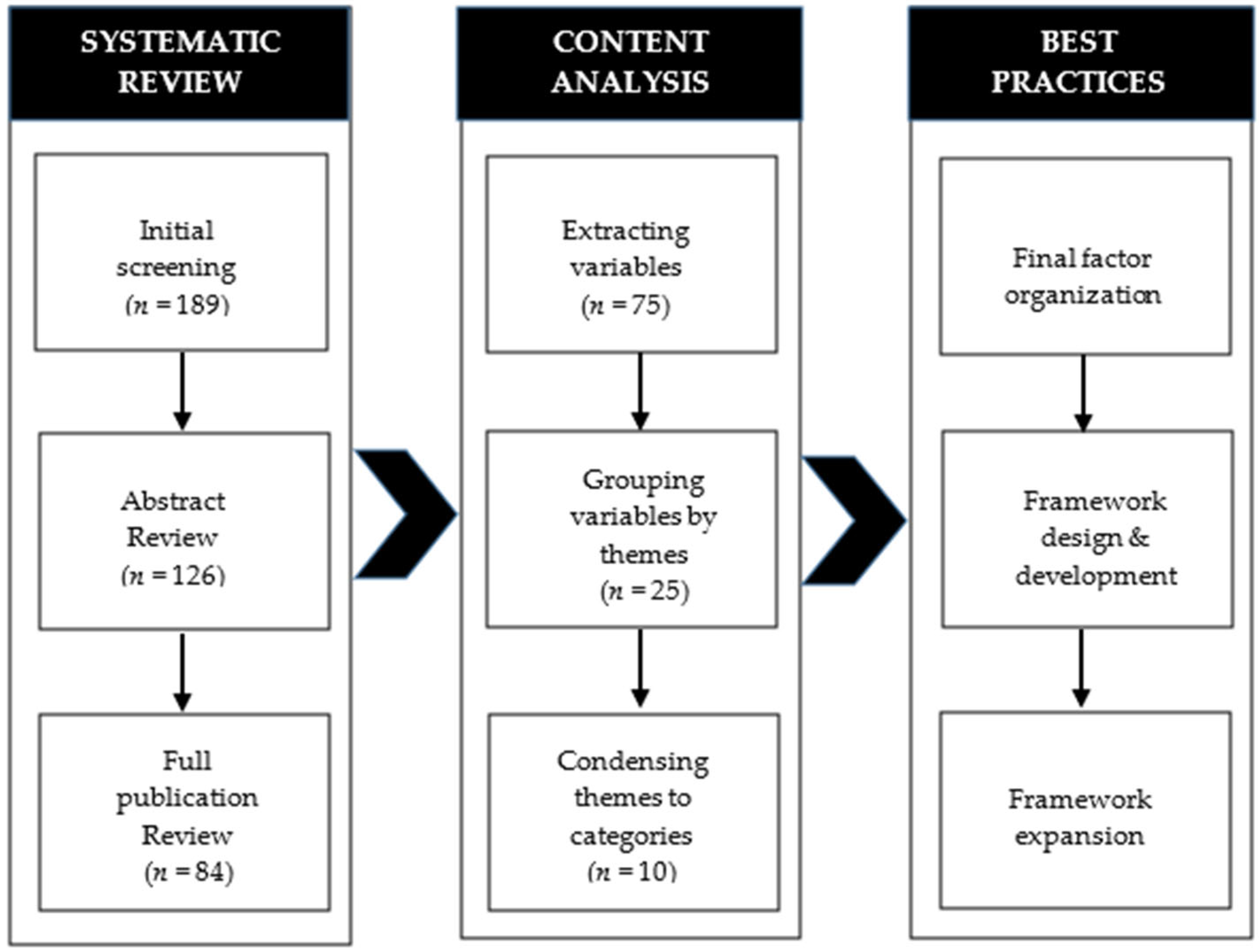
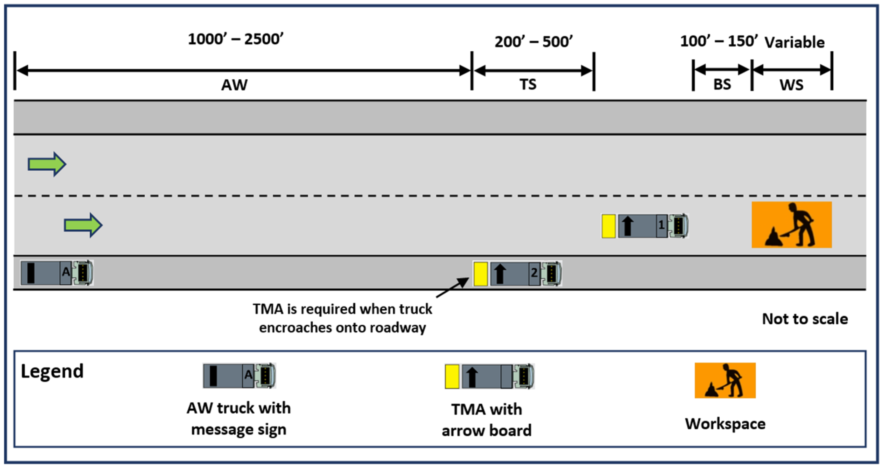
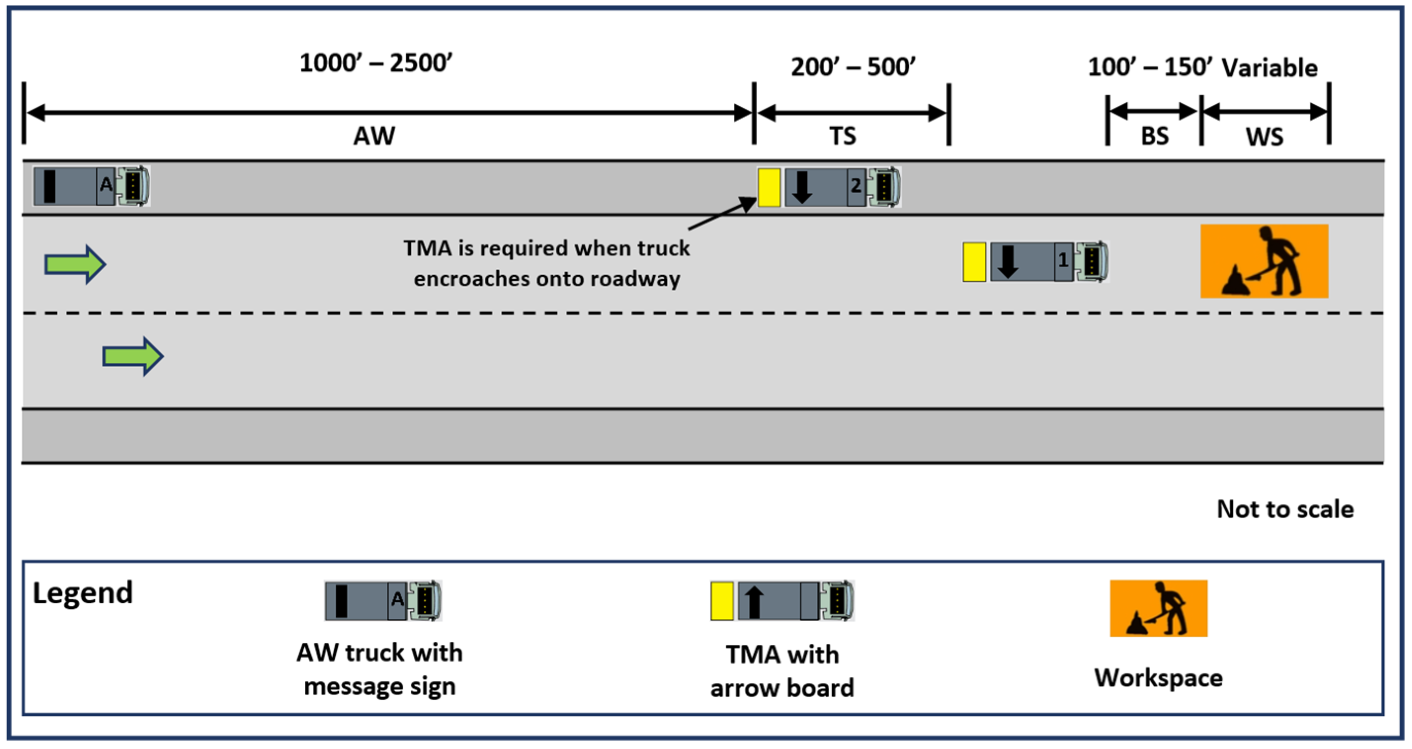
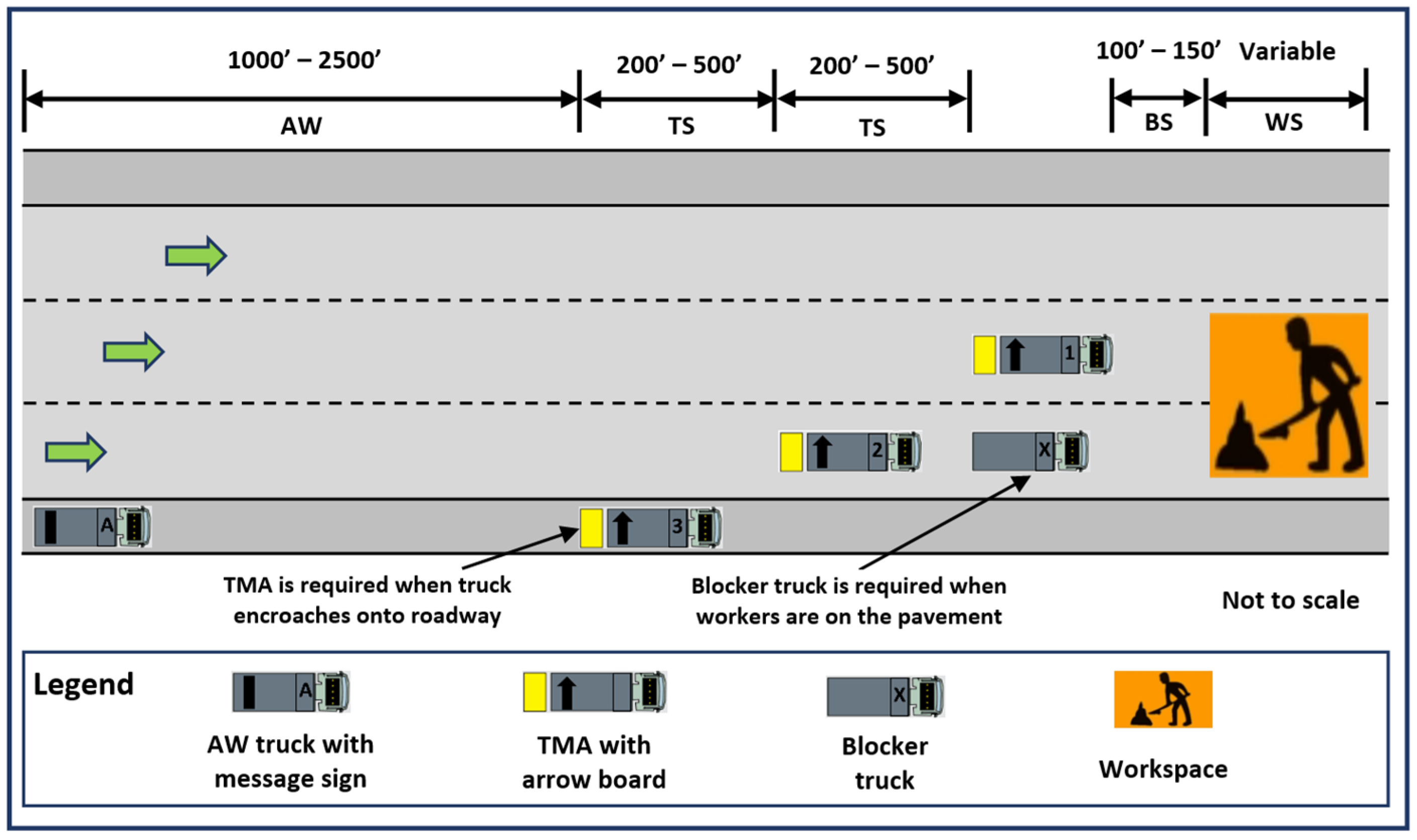
