Abstract
The automation in image acquisition and processing using UAV drones has the potential to acquire terrain data that can be utilized for the accurate production of 2D and 3D digital data. In this study, the DJI Phantom 4 drone was employed for large-scale topographical mapping, and based on the photogrammetric Structure-from-Motion (SfM) algorithm, drone-derived point clouds were used to generate the terrain DSM, DEM, contours, and the orthomosaic from which the topographical map features were digitized. An evaluation of the horizontal (X, Y) and vertical (Z) coordinates of the UAV drone points and the RTK-GNSS survey data showed that the Z-coordinates had the highest MAE(X,Y,Z), RMSE(X,Y,Z) and Accuracy(X,Y,Z) errors. An integrated georeferencing of the UAV drone imagery using the mobile RTK-GNSS base station improved the 2D and 3D positional accuracies with an average 2D (X, Y) accuracy of <2 mm and height accuracy of −2.324 mm, with an overall 3D accuracy of −4.022 mm. Geometrically, the average difference in the perimeter and areas of the features from the RTK-GNSS and UAV drone topographical maps were −0.26% and −0.23%, respectively. The results achieved the recommended positional accuracy standards for the production of digital geospatial data, demonstrating the cost-effectiveness of low-cost UAV drones for large-scale topographical mapping.
1. Introduction
Topographic mapping is carried out for the positioning and extraction of manmade and natural feature objects on the earth’s surface for engineering and related applications. As a consequence of advances in terrestrial survey instruments and techniques and space-based platforms, such as aerial photogrammetry and satellite imaging, the efficiency and accuracy of topographic mapping are continuously advancing [1]. Furthermore, with technological advances, survey instruments are not only becoming smaller in size and more precise in measurements, but they are also now capable of acquiring large data volumes in a shorter duration of time [2,3].
In emerging economies, topographic mapping and the generation of 3D terrain information are often obtained using terrestrial survey instruments, including Electronic Distance Measurements (EDMs), Total Stations, and Global Navigation Satellite Systems (GNSS). These terrestrial-based survey instruments and techniques are, however, costly, labor-intensive, and time-consuming, and more so in difficult topographical complex environments and for the topographical mapping of large areas [4]. Further, despite the ability of these techniques to acquire topographical details with high accuracy, their modes for data capture are based on discrete point measurements, which results in the acquisition of a spatial density of points that are limited in distribution for the construction and representation of near-continuous 2D and 3D terrain models. To acquire higher-resolution 2D and 3D topographic data, photogrammetric imaging, laser scanning, terrestrial LiDAR scanning, and high-resolution satellite remote sensing imaging can be adopted. However, these space-borne techniques are exorbitant in cost, thus expensive to invest in, and are complex and costly in terms of data processing software, and require operational expertise [5]. As such, there is a need for alternative approaches for topographic data acquisition that are not only economically sustainable but also time-efficient and accurate [6,7].
Despite the fact that remote sensing platforms such as satellites present economically efficient and wide-area coverage, their positional altitude and the resulting spatial resolutions are not suitable for the generation of high-spatial-resolution 2D and 3D terrain data, which are required for detailed topographic mapping [8]. Additionally, space-orbiting satellites suffer from a low temporal frequency of data acquisition and are prone to the effects of cloud cover, making them unsuitable for on-demand data provision [9]. On the other hand, while laser scanning and terrestrial LiDAR are capable of providing high-spatial-resolution 2D and 3D terrain information, their limitation is on the expense of these techniques, including instrumentation costs, and the significant expertise needed in data collection and data processing, which collectively do not allow for ease in adoption or frequent utilization [5].
To address the limitations of the remote sensing-based sensors and platforms for 2D and 3D topographical mapping, unmanned aerial vehicles (UAV) have been proposed as a potential alternative for digital topographical mapping [9,10]. From the literature and depending on the industry where used, UAVs are also called unmanned aerial systems (UASs) or referred to as Remotely Piloted Aircraft Systems (RPAS). Other terminologies have been adopted in reference to UAVs, including drones, as summarized by [11], largely depending on their propulsion systems, flight altitude range, and the degree of automation in flight execution.
The are two main types of UAV drones, namely the fixed wing and quad rotor or multirotor UAVs. The payloads for the fixed wing UAV are characterized by lightweight digital cameras used for the acquisition of stereo imagery of large areas [12], while the quadrotor UAVs carry higher sensor payloads; however, these are disadvantaged by the lower flight speeds and short-operating batteries [13]. Compared to satellite image data acquisition, the UAV drone offers superior data in terms of very-high-spatial and high-temporal resolutions and is not affected by clouds [14]. The UAV sensors acquire precise data [15], with sufficient detail for the accurate processing and representation of complex terrains and environments. Adopting a low-cost photogrammetric approach for the reconstruction of high-resolution topographic data, UAVs can be considered economically efficient for large-scale mapping for different applications [16]. As a consequence of the miniaturization and affordability of UAV drone hardware, such as sensors, GPS, and IMUs (inertial measurement units), the adoption of UAVs has considerably increased in recent years [17].
Different experimental studies have been carried out in order to determine the potential of UAV drones for topographical surveys and mapping. Quaye-Ballard et al. [18] compared the UAV drone survey and GPS-RTK survey for mapping inaccessible land and found consumer-grade UAV results to be suitable for topographic mapping with an accuracy of 0.05 m. Chi et al. [12] also carried out UAV drone surveys for the effective generation of digital surface and digital terrain models using quadrotor drones and GCPs in Taiwan. Other studies that have utilized UAV drone surveys include large-scale topographic mapping [19,20,21], generation of digital surface models [22,23,24], and the derivation of volumes of earthworks [25]. Other studies that investigated UAV image data for topographic mapping include [26,27,28,29,30,31]. Refs. [10,21] concluded that due to their rich data acquisition and ability to deliver accurate data, UAV-based surveys have the potential to compete with conventional terrestrial survey methods in terms of accuracy.
Because of the demands for large-scale topographic maps for engineering applications, accurate 2D and 3D measurement methods are necessary for intelligent object and terrain data generation and analysis. While laser scanning and photogrammetric methods are gaining popularity for intelligent 2D and 3D objects and feature mapping, the former is a high-cost technique that also requires complex and intensive processing capabilities. Additionally, laser scanning techniques have limitations in directly generating insufficient information for specific feature objects in an exact global orientation [25]. Compared to the traditional remote sensing platforms, UAVs are more flexible in utilization, lower in cost for image acquisition, and faster in the collection of very-high-spatial resolution (VHR) data collection that is suitable and sufficient for the identification and extraction of terrain objects [32].
In the previous studies employing the DJI Phantom 4 drone for topographical mapping, [33] for the case study of mapping the coastal section of the northern Adriatic Sea (Italy), tested the accuracy of the UAV-RKT survey using RMSE and did not generate or compare the quality of the topographical maps. A related study by [29] on topographic mapping of mixed urban areas also only presented the accuracy of the UAV-RTK survey with RMSE analysis using 15 control points without producing or comparing the topographical maps with classical methods. Nwilag et al. [9] though, presented the output topographic map of the study area; the accuracy was computed only using the RMSE static. From the literature survey on the application of a Phantom 4 drone for topographical surveys, it was observed that the previous studies had the following limitations: (a) a lack of comprehensive workflow testing and comparisons of the RTK-GNSS, UAV-GCP, and UAV-RTK methods; (b) the studies employed few or no checkpoints in accuracy assessments and did not take into consideration the recommended spacing of at least 10% of the diagonal site distance [34,35]; (c) there was no comprehensive accuracy assessment of the accuracy using error metrics, including RMSE and accuracy, as recommend for generating digital geospatial data by ASRS [34] and FGDC [35].
The literature review above indicates that UAVs have been widely established for acquiring high-resolution imagery that is suitable for mapping applications. Despite the benefits being auspicious, the adoption of UAV drones as innovative tools for accurate topographical mapping remains at the feasibility and experimental study levels due to a lack of developed and comprehensive workflows that integrate accuracy assessments with industry standards [36,37]. This study introduces a systematic approach for UAV drone data acquisition and processing based on the SfM (Structure-from-Motion) survey and integrates and compares the outputs and accuracy of the approach with the conventional and classical methods based on ground control points (GCPs) that are precisely measured with GNSS, as well as surveys conducted with an integrated RTK system that avoids the use of GCPs by applying spatial corrections directly to the images. In comparison with the classical topographical mapping methods, the proposed approach will address the question of the stability of UAV-RTK-based surveys by presenting an optimal workflow setup that includes an accuracy assessment for standardization, in addition to highlighting the advantages of rapid organizational and logistical deployment that minimizes the working times and costs.
The aim of this research is to explore the potentiality of utilizing the DJI Phantom 4 UAV drone for large-scale and high-resolution topographic mapping. The successful experimentation of this experimental study will demonstrate the significance and accuracy of low-cost UAV drones for topographic mapping, especially in developing countries with limited project funds, for applications in building and infrastructural engineering projects, environmental management, hazard monitoring, as well as in needs assessments, amongst other areas. For the experimental evaluation of the potential of using low-cost UAV drones for large-scale topographical mapping, this study evaluates the performance of the DJI Phantom 4 RTK in comparison with an RTK-GNSS positioning survey for topographical mapping of a case study that comprises integrated topographical feature objects with different elevations and densities. The objectives of this study are to (a) demonstrate the viability of undertaking topographical mapping using a low-cost UAV drone, including the implementation of a robust workflow drone image acquisition and data processing; (b) determine and analyze the 2D and 3D positional accuracies of the RTK-GNSS and UAV-based surveys; and (c) evaluate topographical mapping output from the two methods in terms of the degree of feature content, accuracy, and topology.
2. Materials and Methods
2.1. Study Area
The study area is located within the University of Botswana in Gaborone, Botswana (Figure 1). The case study area for the experimental topographical survey is situated between latitudes 24°39′35″ S and 24°39′36″ S and longitudes 25°56′17″ E and 25°56′23″ E and covers an area of approximately 5.13 hectares. The university is a rapidly growing organization that continuously undergoes building and infrastructural developments, and therefore, continuous large-scale topographical mapping of the campus is necessary for facilitating physical planning, management, and construction activities.
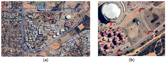
Figure 1.
(a) Location image of the University of Botswana in Gaborone (Botswana), and (b) the location of the case study area. (Source: Google Earth).
2.2. Methods
This research is based on primary data collection using a GNSS survey UAV drone survey. The field data collection and processing were conducted using the DJI GS Pro app [38], Pix4Dmapper® [39], and ArcMap [40] tools. The workflows of the RTK-GNSS and UAV drone topographic survey are summarized in Figure 2. The workflow in Figure 2 comprises three main steps: (a) the establishment of GCPs using a GNSS survey, (b) a UAV drone topographical survey integrating GCPs, and (c) an RTK-GNSS topographical survey. The outputs from the main steps are indicated at the end of the processing steps. The implementation of the steps for Figure 2 is detailed in the subsequent sections.
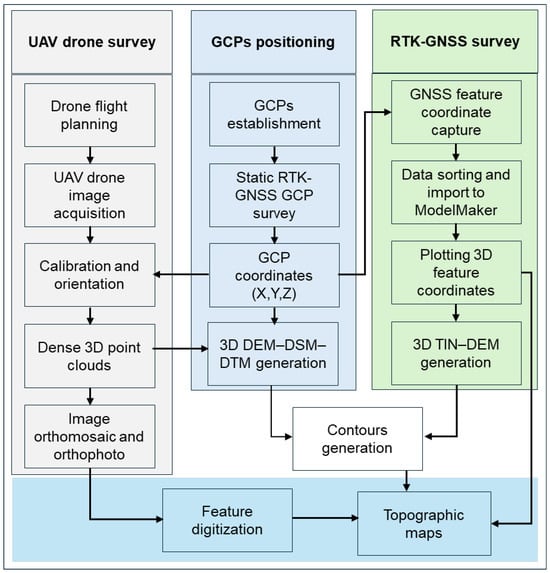
Figure 2.
GNSS and UAV-based topographical mapping workflow. (The GCPs positioning step is placed in the middle (light blue) as it is the primary data requirement for both the UAV drone (gray) and RTK-GNSS (light green) survey processes).
2.2.1. RTK-GNSS Positioning and Topographic Survey
The first step in traditional topographical surveys involves the densification of GCPs from established control stations using GNSS surveys. In Figure 2, the middle workflow shows the steps in GCP establishment using a static RKT-GNSS survey. The GCPs are required in the implementation of the topographical survey approaches using the UAV drone and RTK-GNSS. In this section, a background to GNSS positioning is first presented, followed by the application of RTK-GNSS for topographical mapping.
Using standalone GNSS, the (x, y, z) position is determined by computing the distances between the receiver and at least four satellites (Figure 3a) and solving the observational equations. Standalone observations, however, suffer from large position errors attributable to satellite and receiver clock errors, satellite orbital errors, receiver noise, delays due to ionosphere and troposphere, and signal multipath attenuations [41,42]. These errors result in the superimposition of the phase and coder ranges in standalone GNSS surveys, causing inaccuracies in the (x, y, z) position determinations. The RTK-GNSS positioning approach corrects this limitation by constructing observational differences and using integers to fix the ambiguity. By compensating for the errors, higher precision GNSS positioning is accomplished through differential GNSS positioning.
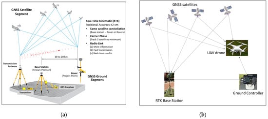
Figure 3.
(a) RTK-GNSS positioning setup. Base station with reference coordinates with correction information from receiving the GNSS positioning signal while the rover obtains (x, y, z) coordinates while receiving the GNSS positioning signal. (b) Integrated RTK and UAV drone for direct georeferencing.
In RTK-GNSS positioning implementation, the base station and rover are set, as seen in Figure 3a. By aggregating the receiving signals in real time, the unknown station local error is analyzed in real time with the base station, and the rover GNSS signal is corrected to determine the precise (x, y, z) position. In terms of the carrier signals, L1 carrier signals do not eliminate the ionospheric delays. By combining the L1 and L2 carrier signals, the RTK-GNSS receivers correct for the ionospheric and tropospheric errors [43]. The additional orbital, satellite, and receiver clock errors and observational biases were corrected through calibration [44].
The RTK-GNSS survey was used to measure the ground control points (GCPs) coordinates and for positional determination of the main topographical features and spot heights that adequately represent the case study area. The GCPs are essential for the orientation and camera calibration, georeferencing, and orthorectification of the acquired image [20]. Given the small size of the study area, GCPs are comprised of 3 constructed targets and 1 pre-established control station (Figure 1b). With the base station established at UBL12 station, the coordinates of the pre-marked GCP stations (UBL08, UBL05, and UBL06) were obtained using the GNSS rover in real-time RTK mode. The rover was set up at each point for a minimum of 30 s stop-and-go to receive and analyze the correctional signals from the base station. In addition to the GCPs, thirteen independent checkpoints (ICPs) were identified for 2D and 3D positional accuracy assessments. The Leica GS14 GNSS system was used for the field survey to obtain the 2D and 3D coordinate data. The Leica GS14 GNSS can receive L1 and L2 frequencies with a vertical accuracy of 1.5 cm ± 1 ppm and a horizontal accuracy of 0.8 cm ± 1 ppm in RTK mode [45]. The detailed specifications of the RTK-GNSS receiver are presented in Table 1.

Table 1.
Specifications of the Leica GS14 GNSS [45].
2.2.2. UAV Platforms and the DJI Phantom 4 UAV Drone Characteristics
This study used the multirotor (quadcopter) DJI Phantom 4 UAV drone [38]. The multirotor drone mechanism can carry a higher payload capacity, such as digital single-lens reflex (DSLR) cameras. DJI Phantom 4 RTK/PPK drones are also equipped with a high-accuracy GPS antenna. The antenna can also be used to store the L1 and L2 dual-frequency GPS satellite observations for post-processing. A summary of the DJI Phantom 4 specifications is presented in Table 2.
Table 2.
DJI Phantom 4 aircraft, sensor, and GNSS capability specifications [38].
The DJI Phantom 4 (DJI-P4) is equipped with a 1-inch CMOS sensor with a resolution of 20 megapixels and pixel dimensions of approximately 2.4 µm, which is larger than the other sensors found in most other consumer drones. This sensor size results in a crop factor of approximately 2.7× compared to a full-frame (35 mm) sensor. This crop factor affects the effective focal length and FOV of the camera. For instance, the DJI-P4 lens has a focal length of 8.8 mm, which, when multiplied by the crop factor, provides an effective focal length equivalent to a 24 mm lens on a full-frame camera. The sensor’s physical dimensions and pixel density directly influence the pixel ground sampling distance (GSD). For example, at a flight altitude of 100 m above ground level, the GSD is approximately 2.7 cm/pixel. The quality of the camera sensor and lens system plays a crucial role in the accuracy of geometric models derived from drone imagery. The DJI-P4 camera features a mechanical shutter, which minimizes the rolling shutter effects that can distort moving objects or rapidly changing scenes. Additionally, the camera offers a wide aperture range (f/2.8 to f/11), allowing for flexibility in various lighting conditions. However, several factors, such as lens distortion, sensor noise, motion blur, and georeferencing errors, can degrade the geometric information content of the models derived from the DJI-P4. Despite these, the DJI-P4 has demonstrated high geometric accuracy in photogrammetric applications [33,46,47].
2.2.3. Flight Planning and Drone Image Acquisition
The quality of the drone-derived DSM, DEM, and orthomosaic is dependent on the accuracy of the acquired image and the ground sampling distance (GSD) or the spatial resolution of the drone digital image. GSD is estimated through the flight planning stage. In this study, flight planning was carried out using the DJI GS Pro app, which was chosen over other applications, as it provides an added functionality for calibrating the UAV’s sensors as well as the gimble image stabilization unit, which ensures stable and accurate data collection. The expected GSD for suitable flying height (H) is calculated using Equation (1) [48]:
where = the width of the sensor (mm); = the sensor camera focal length (mm), and = the image width.
The flying height was set at 30 m, which translates to a GSD of 1.8 cm/pixel. The forward overlap was set to 80%, and the side overlap was set to 60% to have the most overlaps between images and to minimize any risk of gaps in the imagery, which would result in deformation in the final orthomosaic and the related products. The low-altitude flight provided overlapping images of the study area, providing a total of 1061 images for the study area covered. The DJI GS Pro app was used to set the flight direction perpendicular to the longer side (Figure 4) so as to acquire more overlapping image data, which is suitable for accurate 2D and 3D reconstructions. A course angle of 136° was determined to be the most appropriate for the site. With the parameters set, the flight time to collect the data was 41 min 35 s. Figure 4 shows the autonomous and parallel flight trajectories for capturing overlapping and geotagged imagery of the study area.
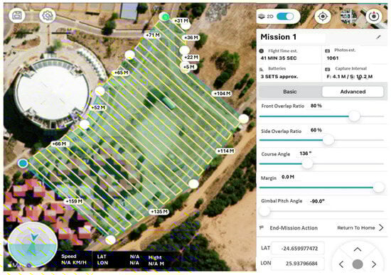
Figure 4.
DJI Phantom 4 flight plan and trajectory for overlapping geotagged photographs.
2.2.4. SfM Photogrammetric Processing for Orthomosaic and 3D Terrain Data Generation
Orthomosaics are geometrically corrected images that account for lens distortion, camera orientation (pose), and terrain-induced relief displacement. The resulting imagery is accurately scaled and georeferenced, making it suitable for the generation of both 2D and 3D geospatial products such as orthophotos, digital elevation models (DEMs), and digital surface models (DSMs) [49]. For this study, PIX4Dmapper® software was used to process UAV imagery and generate orthomosaics and terrain models. The processing workflow is based on the Structure-from-Motion (SfM) technique, a photogrammetric method that reconstructs 3D models from multiple overlapping 2D images. SfM is particularly effective with low-cost RGB cameras, providing high-spatial resolution and metric accuracy in the resulting models [50]. The SfM photogrammetric workflow is summarized in the following steps:
Step 1: Image alignment and camera pose estimation: The first step involves the automatic detection and matching of tie points (or key features) across multiple overlapping images using the SIFT (Scale-Invariant Feature Transform) algorithm, implemented through SiftGPU in PIX4Dmapper®. SiftGPU employs automated aerial triangulation using bundle block adjustment, which minimizes projection errors across images and ensures geometric consistency. The matched features are used to estimate the internal orientation parameters of the camera and compute the exterior orientation (EO) parameters, which include the camera’s 3D location (X, Y, Z) and the camera’s orientation angles (ω, φ, κ). This stage results in a sparse point cloud and an initial camera network geometry. Figure 5 illustrates the concept of a sparse point cloud derived from matched tie points across overlapping UAV images.
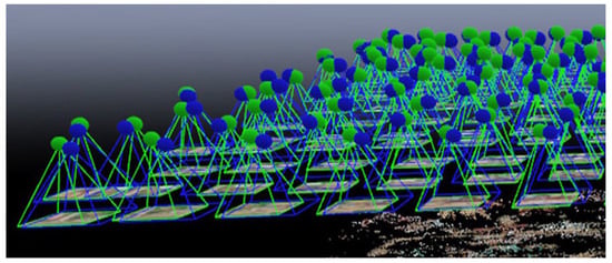
Figure 5.
Sparse point clouds illustration. (Screenshot: PIX4Dmapper®).
Step 2: Dense point cloud generation: Once the sparse point cloud and camera poses are established, pairwise depth maps are calculated between overlapping images to generate a dense 3D point cloud. This step significantly increases the level of surface detail and is essential for high-resolution 3D surface modeling. For computational efficiency, images may be resampled (e.g., to 1/4 resolution) while still retaining sufficient accuracy for the DSM and orthomosaic generation. Both sparse and dense clouds are georeferenced using GCPs to enhance the absolute positional accuracy.
Step 3: 3D models derivation and orthomosaic generation: The dense point cloud is used to interpolate surface models such as the DSM and DEM. These elevation models serve as the geometric basis for the generation of the orthomosaic, which is a radiometrically and geometrically corrected 2D image mosaic. Each image pixel is orthorectified based on elevation data and EO parameters, resulting in a seamless, spatially accurate image. From the orthomosaic, topographic feature extraction can be performed through manual or automated digitization techniques, enabling the mapping of land cover, infrastructure, and terrain features.
2.2.5. Direct Georeferencing of UAV Drone Imagery Using RTK-GNSS Base Station
The use of GCPs for georeferencing UAV imagery presents several limitations, particularly related to the logistical and financial costs of acquiring high-precision GNSS measurements. This challenge is further exacerbated in remote or inaccessible areas where deploying GCPs is impractical or hazardous. As an alternative, direct georeferencing provides a method for determining the spatial orientation and position of captured imagery without relying on an extensive network of GCPs. By eliminating or minimizing the need for ground control, direct georeferencing significantly reduces fieldwork requirements while still enabling the generation of high-accuracy geospatial products such as digital surface models (DSMs), orthomosaics, and topographic maps. Unlike traditional GNSS surveys (Figure 3a), direct georeferencing integrates sensor data collected onboard the UAV platform (Figure 3b) with image position geometric correction. The configuration was comprised of the UAV equipped with an RTK-GNSS receiver and an inertial measurement unit (IMU). The RTK-GNSS provides high-precision measurements of the camera’s spatial position in Earth-centered coordinates (X, Y, Z), while the IMU captures the (ω, φ, κ) angular orientation parameters at the exact time of image exposure.
The coordinates and the orientation parameters constitute the six elements of exterior orientation (EO), which are essential for transforming image coordinates into real-world coordinates within a photogrammetric workflow. By leveraging these EO elements, direct georeferencing facilitates accurate image registration and 3D spatial reconstruction, effectively reducing or even eliminating the need for ground-based reference points. When properly calibrated, this approach maintains centimeter-level geometric accuracy, making it suitable for a wide range of mapping and surveying applications [51].
2.3. Accuracy Assessment
The accuracy measurement is based on the positional differences between the GNSS-measured and UAV-derived 2D and 3D coordinates of GCPs and independent checkpoints (ICPs); the National Standard for Spatial Data Accuracy (NSSDA) standards for geospatial consistency checking were adopted [35,52]. The NSSDA uses the Root Mean Square Error (RMSE) and accuracy measurements to estimate the positional (x, y, z) accuracy between the GNSS reference measurements and the UAV-derived orthomosaic coordinates. In addition, the Mean Absolute Error (MAE) measurement was also computed for comparison with the two accuracy matrices.
where n is the number of control points for the study, and are, respectively, the GNSS observed and the orthomosaic measured X-, Y-, and Z-coordinates. and are the RMSEs in 2D and 3D, respectively, and refers to the accuracy derived in 2D and 3D. The accuracy is determined at the 95% confidence level [35]. The accuracy is a measure of the degree of uncertainty that is characterized by the control coordinates and feature extraction procedures.
3. Results
3.1. Topographic Mapping Using RTK-GNSS and UAV Drone Surveys
From the spot heights obtained from the GNSS survey, the DEM, contours, and topographic map of the study area were produced, while from the UAV drone, dense point clouds were used to generate the orthomosaic, DEM, DSM, contours, and topographic map (Figure 6, Figure 7, Figure 8, Figure 9 and Figure 10). Figure 6a shows the dense point clouds from the UAV drone imaging, and the output orthomosaic image for the area is presented in Figure 8. By gridding the area and summarizing the elevations of the points falling within each cell, the resulting DEMs from the GNSS survey spot heights (Figure 7a) and drone data (Figure 7b) were derived at a spatial resolution of 1.8 cm/pix, with the elevations varying from 978.462 m to 981.923 m AMSL. Visually, the drone-derived DEM (Figure 7b) presents a much smoother DEM surface as compared to the GNSS survey-generated DEM. This is expected as the dense point clouds present higher-resolution 3D coordinates, which, when interpolated, result in higher-resolution DEMs.
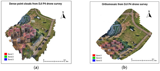
Figure 6.
UAV drone (a) point clouds and (b) orthomosaic.
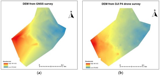
Figure 7.
DEMs derived from (a) GNSS and (b) UAV drone surveys.
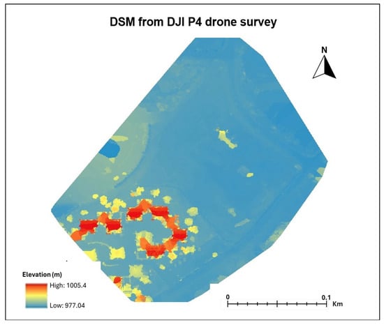
Figure 8.
DSM derived from UAV drone survey.
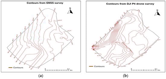
Figure 9.
Contours from (a) GNSS and (b) UAV drone survey.
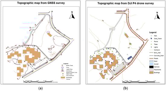
Figure 10.
Topographic maps obtained from (a) GNSS and (b) UAV drone surveys.
The scene DSM was derived by extracting the elevation data from the 3D point cloud, which contains the heights of all the surface features, including buildings, vegetation, and terrain, thus creating a detailed 3D representation of the landscape (Figure 8). GNSS surveys are, however, not able to generate a DSM due to the impossibility of measuring the higher elevated 3D coordinates of features like trees and buildings. At the same pixel resolution as the DEMs, the DSM in Figure 8 shows the lowest elevation at 977.04 m AMSL, and the highest point has an elevation of 1005.4 m AMSL. For the topographical analysis of the entire scene, a larger area DSM was generated as compared to the DEM sizes in Figure 7.
The DEMs generated in Figure 7 were used to derive the contours for the study area, with the results seen in Figure 9. At the same contour intervals of 0.25 m, higher-resolution contours were obtained from the drone-derived DEM (Figure 9b), as compared to the GNSS-derived contours (Figure 9a). The drone survey data produced more dense contours as compared to the GNSS survey, especially in the densely built-up areas. The dense contours from the drone survey are more suitable for planning, building, and infrastructure development projects.
The final output is the topographic maps of the study area presented in Figure 10. It is observed in Figure 10 that the two approaches produced topographic maps with different details, with the GNSS producing relatively sparse features (Figure 10a) as compared to the more dense and detailed features from the UAV drone survey and feature extraction (Figure 10b). The observation in Figure 10b is attributed to the orthomosaic mosaic in Figure 6a, presenting high-spatial-surface density information that represents more features (Figure 10b) as compared to the traditional GNSS spot height-based topographic survey results (Figure 10a). Overall, the detailed data from the orthomosaic are observed to be more suitable for the generation of large-scale maps, as represented in Figure 10b. The results indicate that undertaking topographic mapping using ground-based methods such as GNSS is not only time-consuming but may not yield the required level of detail, particularly when mapping areas with complex features.
The very-high-spatial imagery acquired using the UAV drone survey and the derivatives are demonstrated to be suitable for topographic mapping. This is demonstrated by the quality of the acquired imagery and the generated orthomosaic and 3D models. Thus, as compared to satellite-based imaging platforms, the lower flying heights, high image overlaps, and low ground sampling distance make it possible to create higher resolutions with more terrain information [20]. The orthomosaic represents the object features in their true orthographic positions and thus is geometrically equivalent to a planimetric map and has the advantage of containing richer feature information.
3.2. Geometric Accuracy Assessment
3.2.1. 2D and 3D Positional Accuracy
The positional accuracy in this study was determined using the RMSE computed from the difference in the coordinates of the GCPs and ICPs, as produced by the UAV drone and RTK-GNSS surveys. The accuracy determined in the differences at each GCP for the five GCPs is shown in Table 3. The GCP positional errors in Table 3 show very close positional agreements between the GNSS and drone-based surveys for the (X, Y) coordinates. However, the Z-coordinates have an absolute average positional error of 1.5 cm. In Table 4, the RMSE and the accuracy measurements are the least in the X- and highest for the Y-coordinates. For the 2D measurements, the RMSE XY, MAE XY, and accuracy XY measures are, respectively, at 0.5 cm, 0.2 cm, and 0.8 cm. The 3D combined error measurements are determined as RMSEXYZ (1.9 cm), MAE XYZ (1.5 cm), and accuracy XYZ (3.3 cm). The accuracy measurements fall within the allowable RMSE and accuracy, as specified by the ASPRS [34] and FGDC [35] standards.
Table 3.
GNSS- and UAV-GCP coordinates and positional measurement errors.
Table 4.
GCP accuracy measures.
For the independent checkpoints (ICPs), the positional accuracy results in Table 5 show the same trend as for the GCPs in Table 3 above, with the 2D coordinates being more accurate than the Z-coordinates, with positional average errors of −0.2 cm and –14.9 cm, respectively. The RMSEXY (0.6 cm), MAEXY (0.4 cm), and AccuracyXY (1 cm) are observed to be much higher than the RMSEXYZ (25 cm), MAEXYZ (22 cm), and AccuracyXYZ (43 cm) for the ICPs. From the summary results for the ground level and elevated ICP in Table 6, the difference between the GCP and ICP accuracy is attributed to taking measurements of checkpoints that are above the ground surface, as compared to the GCPs, which are all at the ground surface level. The RMSExy determined from the 13 independent checkpoints was within the ASPRS [34] and FGDC [35] accuracy standards.
Table 5.
Measured independent checkpoint (ICP) coordinates and ICP errors.
Table 6.
Accuracy measures for checkpoints.
From the results in Table 5 and Table 6, the average RMSExy and AccuracyXY were less than 0.05 m, which compares well with previous studies. In a study in southern Alberta, Whitehead and Hugenholtz [53] carried out topographical mapping using the eBee drone and achieved horizontal and vertical accuracies of 5 mm and 6 mm, respectively, while Elkhrachy [48] processed the drone data using the Agisoft PhotoScan and Pix4Dmapper with four reference GCPs, resulting in horizontal accuracies of 0.038–0.330 m and 0.06–0.098 m and vertical accuracies of 0.05–0.510 m and 0.061–0.384 m, respectively. Quaye-Ballard et al. [18] also determined the horizontal accuracy at 0.05 m for topographical mapping, and Yu et al. [54] reported horizontal (0.040–0.100 m) and vertical (0.037–0.060 m) accuracies in mapping hill slopes and flat land using UAVs.
The results from previous studies show that the accuracies in the horizontal dimensions were higher than in the vertical dimensions. While this is the case for previous studies that did not include tall buildings and trees in their vertical checkpoints, the results of the current study show that the inclusion of high or elevated feature objects reduces vertical accuracy. However, for topographical mapping, the accuracy in the RMSEx, RMSEy, and RMSExy horizontal dimensions is allowable based on the ASPRS [34] standards for large-scale topographical maps [55].
3.2.2. Areal Geometric Accuracy
To compare the locational and extent accuracy of the mapped topographical map features from the two survey methods, the perimeters and areas of five features were computed, and the percentage differences between the GNSS and UAV drone-mapped features were determined. The differences in the areal extents were also visualized by overlaying the features extracted from the two survey methods. The results for the feature perimeter and area differences are presented in Figure 11 and Table 7, and the feature overly results are presented in Figure 12.
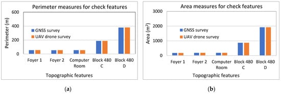
Figure 11.
Accuracy of closed features from (a) perimeter and (b) area measurements.
Table 7.
Accuracy measures for topographic feature perimeter and areas.
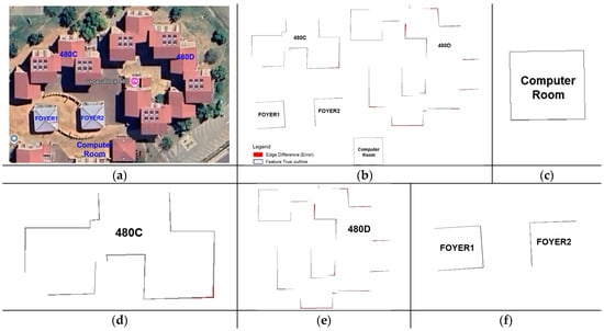
Figure 12.
(a) Study area building features from Google Earth. (b–f) Overlay of extracted topographic features from GNSS and UAV drone surveys.
In terms of the perimeter (Figure 11 and Table 7), the difference between the GNSS and drone survey coverages was less than ±1 m, except for the largest building block, which recorded +2.6 m more in the perimeter, resulting in an error of −0.7%. Overall, the average feature perimeter accuracy was −0.635 m (−0.26%). For the same features, the average area coverage error was detected at −0.001 m2 (−0.23%). This shows negligible differences between the feature mapping from the two methods, which is illustrated in Figure 12 through an overlay of a section of the two topographical maps. For the original building features in Figure 12a, the overlay results between the two methods in Figure 12b indicate that only marginal outline differences are detected at the corners of the building features and in complex structures (Figure 12c–f).
For the entire scene, the geometric, positional, and scale differences between the main topographic features (buildings, paved surfaces, and main roads), as mapped from the GNSS and UAV drone surveys, are presented in Figure 13 and clearly indicate a better distribution of the mapped features differences. The differences, represented by colors, are the absolute magnitudes of the losses and gains in the feature outlines after subtraction. In terms of the geometry of the topographic features, both the GNSS and UAV drone surveys were observed to capture the features accurately, giving correct and comparable feature shapes, also depicted in Table 7, with marginal differences in geometric sizes, especially for buildings. For 2D positional mapping, there are detectable marginal differences in the positions, as visually determined (Figure 13) and statistically represented by the RMSE and accuracy measurements (Table 6). From the geometric and positional differences, it is inferable that the scale and sizes of the topographic features are marginally different, which is not acceptable from geomatics industry standards and applications. This implies that UAV drone surveys should be improved in accuracy to be as accurate as the RKT-GNSS surveys.
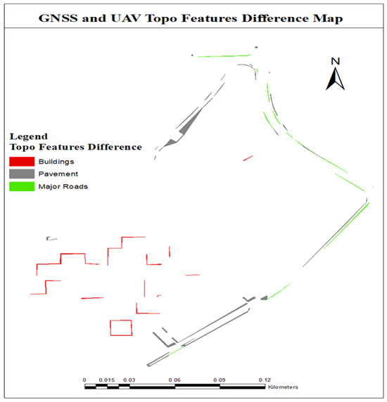
Figure 13.
Topographic features difference image between the RTK-GNSS and the GCP-UAV drone surveys.
4. Discussion
4.1. Performance of RTK-GNSS and UAV Drone for Topographic Mapping
In the analysis of the UAV drone-based survey, it is inferable that the semi-automated process for image acquisition and image processing allows for efficiency, consistency, and precision in image data acquisition, image parameter determination, and quick data capture, thus offering cost-effectiveness. Based on this, it is evident from the results that the quality of the 3D data and models generated using the UAV drone surveys is superior compared to the RKT-GNSS-based measurements in terms of data density and accuracy when compared to the ground-based survey methods. While traditional aerial photography using manned aerial photography continues to be used for mapping large areas on small scales, UAV drone image acquisition has been observed to be more cost-effective and suitable for mapping smaller and inaccessible areas [56]. The case study results indicate that UAV-based mapping can serve as an alternative to terrestrial-based methods, especially for small-sized 2D planimetric mapping, with the potential to enhance data capture efficiency, cost and time savings, and in generating richer data that are suitable for a more accurate generation of topographical maps [37]. Using a DJI Phantom 4 Pro drone, Nogueira et al. [57] obtained and processed imagery using Pix4D Mapper Pro to map a 15-hectare site with GCPs for georeferencing. Lima et al. [58] and Zhang et al. [59] also demonstrated the suitability of the DJI Phantom 4 Pro drone for deriving 3D (X, Y, Z) coordinates with 15 GCPs and 47 ICPs, with both studies providing timely and cost-effective topographic map information.
For 3D terrain mapping, these study results show that the GNSS-RTK and UAV drones present nearly similar estimates for DEM generation, except that the drone approach is much faster and more accurate, as it is automatically derived from point clouds. For the same area of 5.13 hectares, the UAV drone survey only took 42 min to conduct the fieldwork, while the RTK-GNSS survey took two working days. Similarly, the results for the contour generation depict the drone presenting more dense, accurate contour intervals. The use of UAVs is thus observed to be useful for the quick derivation of accurate and high-resolution DEMs, as was also observed in previous studies [37,60,61,62]. When georeferenced with accurate GCPs, UAVs can capture and photogrammetrically process and deliver spatial data with rich spatial, spectral, and temporal detail that is suitable for high-quality standards of mapping [62,63,64,65]. The accuracy of the DEMs derived from UAVs is observed to be higher for low-laying and bare or grass-covered areas, an observation also made by Coveney and Roberts [66]. Importantly, the use of UAVs for 2D and 3D mapping is likely to increase as the costs for acquiring UAVs are observed to decrease, making technology accessible to a wider range of users.
From the case study results and considering the potential and advantages of using the UAV drone for topographic mapping, there is a need to improve the precision and accuracy of a drone-derived aerial orthomosaic. To explore the minimization of the positional accuracy errors for the 2D and 3D coordinates acquired from drones and in producing orthomosaics, integrated direct drone image georeferencing using the GNSS-RTK mobile base station was tested using the setup in Figure 3b. UAVs with lightweight RTK systems enable the precise location determination of the UAV 3D poses and can be applied for local-scale mapping [67].
While the use of UAV drones has been recommended as being more cost-effective and suitable for mapping remote, inaccessible terrain [56], the operationalization of drones in such environments also poses challenges. The challenges include the transportation logistics to the site, setting up of the drone, RTK-GNSS, and related equipment, and for areas with inclined slopes and that are mountainous, it will be difficult to fly a drone in a stable mode, including a safe and efficient take-off and landing, and to acquire accurate images of the scene [68]. In difficult-to-access sites, recommendations include adopting compact and lightweight drones with GPS stabilization, drones equipped with advanced navigation systems and automatic safety features, and utilizing higher-resolution imaging sensors.
4.2. Integrated Direct Drone Image Georeferencing for Accuracy Improvement
With UAV systems now integrated with GNSS/INS capabilities, direct positioning has improved accuracy to the subcentimeter level, and it is thus possible to directly georeference the acquired drone imagery using GNSS stations connected to the UAV system, which exploits RTK positioning techniques [69,70]; hence, minimizing the need for acquiring GCPs. The reliability of UAV drone surveys in the RTK mode has been investigated by Tomaštík et al. [71], who developed several tests and concluded that, as compared to the use of GCPs, the most accurate results for both horizontal and vertical accuracies were achieved using the integrated UAV-RTK approach. Ekaso et al. [67], evaluating the DJI Matrice 600 Pro, determined that direct georeferencing with an onboard GNSS-RTK generated a photogrammetric product with decimeter accuracy. Przybilla et al. [72] tested different drones with various flight configurations and found that the RTK-UAV integration led to accurate positional results, even with a single GCP. Adopting the experimental setup in Figure 3b and based on the same flight plan and GCPs (Figure 4), the resulting orthomosaic was used to derive and compare the overall 2D and 3D positional accuracies and the topological geometric corrections.
From the experimental results comparing the GNSS-RTK-measured coordinates and the derived coordinates from the RTK drone that integrated direct georeferencing, the errors in the 2D (x, y) coordinates were observed to be negligible and nearly of the same error magnitudes as those observed from the GNSS-RTK and GCP-UAV drone results (Table 3, Table 4, Table 5, Table 6 and Table 7) for both the positional and geometric accuracies. On the other hand, the height (z) errors were reduced significantly using the RTK drone-integrated mapping approach, with the comparative accuracy results for the GCPs and ICPs presented in Figure 14. Since the (x, y) positional and planimetric (perimeter and area) errors were found to be similar in magnitude between the GCP drone- and RTK drone-integrated results, their results are not presented.
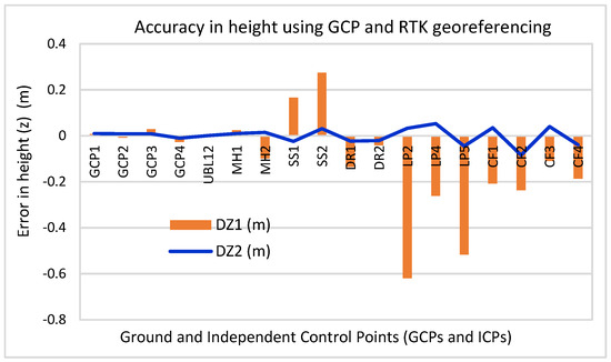
Figure 14.
Height accuracy comparison between GCP-UAV and automated RTK-UAV georeferenced drone imagery.
From the results in Figure 14, the average height (z) error using the GCP georeferenced drone image data is determined at −0.1077 m, with min and max errors of 0.008 m and −0.619 m, respectively, while the average z-errors from the RTK automatically georeferenced imagery is 0.001 m, with a respective min and max error magnitude of 0.002 m and −0.084 m. Comparatively, the results in Figure 14 indicate the outcome of the RTK-UAV survey, with improvements in the 2D geometric and positional accuracy of the topographic features and no significant systematic deviations in the compared features. In terms of the accuracy measures, the improvements in the height accuracy resulted in an increase in the 3D positional accuracies for both the ground level and the elevated ICP (Table 6) to average z-error values of the RMSE (−2.324 mm), MAE (−1.991 mm), and overall accuracy of −4.022 mm. The results indicate the potential of employing the GNSS-RTK base station receiver coupled with a UAV for automatic georeferencing of image data and the generation of orthomosaic results in a higher 2D and 3D accuracy for topographical mapping [69,73]. Similar improved results in the height dimensions and the overall 3D accuracy, based on the integration of GNSS-RTK and UAVs, were also obtained by [74] in their demonstration of the efficiency of low-cost UAVs for the reconstruction of detailed and precise DEMs.
For most developing countries, the demand for topographic geospatial data is increasing. However, the timely production of the desired topographical data is constrained by limited budgets. Even though most countries still rely on EDMs, Total Station surveys, and GNSS are the standards for topographic surveys, as they are recommended to provide spatially accurate and standardized data. This study demonstrates that UAV surveys can provide more accurate data that is richer in 2D and 3D topographical information.
5. Conclusions
The need for large-scale and high-resolution topographic datasets is growing in demand in the design and development of civil engineering and built environment-related projects. UAV-based photogrammetry introduces a low-cost alternative to the classical topographical surveys that rely on expensive traditional survey equipment and aerial photogrammetry for large-scale topographic mapping. This study compared RKT-GNSS- and UAV drone-based surveys for the production of a large-scale topographic map. From the GNSS survey, DEMs, DSMs, contours, and topographic maps were derived, while the UAV drone survey products comprised point clouds, orthomosaics, DEMs, DSMs, contours, and the topographic map of the studied area. For positional accuracy determination, a comparison of the GCP coordinates from the two surveys showed that for 2D coordinates, the RMSE XY, MAE XY, and Accuracy XY measures were 0.5 cm, 0.2 cm, and 0.8 cm, respectively, as compared to the 3D average positional error measurements of the RMSEXYZ (1.9 cm), MAEXYZ (1.5 cm) and Accuracy XYZ (3.3 cm). From independent checkpoints (ICPs), the average 2D coordinate accuracies were determined as the RMSEXY = 0.6 cm, MAEXY = 0.4 cm, and AccuracyXY = 1 cm, as compared to the RMSEXYZ = 25 cm, MAEXYZ = 22 cm, and AccuracyXYZ = 43 cm for the 3D coordinates for the ICPs. By integrating the drone with the mobile RTK base station for automated georeferencing of the acquired drone imagery, the 2D and 3D positional accuracy of the orthomosaic improved with an average 2D (x, y) error of RMSEXYZ ≈ AccuracyXYZ of <2 mm and average z-error values of RMSE = −2.324 mm and AccuracyXYZ = −4.022 mm. The average difference in the perimeter and areas of the topographic features between the RTK-GNSS and UAV drone topographical maps was determined at −0.26% and −0.23%, respectively, indicating that the UAV survey marginally overestimated the feature outlines. The results for the accuracy of the areal extents of the mapped features in terms of the perimeter and area comparisons also demonstrated that the UAV drone survey is suitable to produce 2D engineering survey-grade topographical maps. Compared to the traditional GNSS method, the results from this study show that UAV-based photogrammetry can offer a quick turnaround and efficiency in topographic data collection without any significant loss in accuracy, thus saving time and costs. While it is noted that consumer-grade UAV drones do not possess the direct capability for an immediate substitution of survey-grade equipment, related measuring techniques, or output accuracies at different mapping scales, further experimentation, standardization, and regulatory measures are necessary for the realization of the potential of using low-cost drones for wide-area large-scale topographical mapping. This study recommends further topographic mapping investigations for larger areas and the use of consumer-grade RTK-GNS-equipped UAVs for automated georeferencing of acquired imagery.
Author Contributions
Conceptualization, Y.O.O. and S.M.D.; methodology, Y.O.O. and S.M.D.; software, S.M.D.; validation, S.M.D.; formal analysis, Y.O.O. and S.M.D.; investigation, S.M.D.; data curation and writing, Y.O.O. and S.M.D.; project administration, Y.O.O. All authors have read and agreed to the published version of the manuscript.
Funding
This research received no external funding.
Institutional Review Board Statement
Not applicable.
Informed Consent Statement
Not applicable.
Data Availability Statement
The Department of Civil Engineering (University of Botswana) and the Land-Water Nexus project are acknowledged for providing the equipment and materials used for the fieldwork.
Conflicts of Interest
The authors declare no conflicts of interest.
References
- Wolf, P.R.; Dewitt, B.A.; Wilkinson, B.E. Elements of Photogrammetry with Applications in GIS, 4th ed.; McGraw Hill Education: New York, NY, USA, 2014; ISBN 978-0-07-176112-3. [Google Scholar]
- Zolkepli, M.F.; Ishak, M.F.; Abu Talib, Z. Unmanned aerial vehicle (UAV)-based for slope mapping and the determination of potential slope hazard. Int. J. Integr. Eng. 2022, 14, 232–239. [Google Scholar] [CrossRef]
- Bondarchuk, A.S. System of technical vision for autonomous unmanned aerial vehicles. IOP Conf. Ser. Mater. Sci. Eng. 2018, 363, 012027. [Google Scholar] [CrossRef]
- Tang, P.; Vick, S.; Chen, J.; Paal, S.G. Chapter 2: Surveying, geomatics, and 3D reconstruction. In Frastructure Computer Vision; Elsevier: Amsterdam, The Netherlands, 2020; pp. 13–64. [Google Scholar] [CrossRef]
- Brunier, G.; Fleury, J.; Anthony, E.; Gardel, A.; Philippe, D. Closerange airborne structure-from-motion photogrammetry for high-resolution beach morphometric surveys: Examples from an embayed rotating beach. Geomorphology 2016, 261, 76–88. [Google Scholar] [CrossRef]
- Jiménez-Jiménez, S.I.; Ojeda-Bustamante, W.; Marcial-Pablo, M.D.J.; Enciso, J. Digital Terrain Models Generated with Low-Cost UAV Photogrammetry: Methodology and Accuracy. ISPRS Int. J. Geo-Inf. 2021, 10, 285. [Google Scholar] [CrossRef]
- Ren, H.; Zhao, Y.; Xiao, W.; Hu, Z. A review of UAV monitoring in mining areas: Current status and future perspectives. Int. J. Coal Sci. Technol. 2019, 6, 320–333. [Google Scholar] [CrossRef]
- Kopačková-Strnadová, V.; Koucká, L.; Jelének, J.; Lhotáková, Z.; Oulehle, F. Canopy top, height and photosynthetic pigment estimation using parrot sequoia multispectral imagery and the unmanned aerial vehicle (UAV). Remote Sens. 2021, 13, 705. [Google Scholar] [CrossRef]
- Nwilag, B.D.; Eyoh, A.E.; Ndehedehe, C.E. Digital topographic mapping and modelling using low altitude unmanned aerial vehicle. Model. Earth Syst. Environ. 2023, 9, 1463–1476. [Google Scholar] [CrossRef]
- Perera, G.S.N.; Nalani, H.A. UAVs for complete topographic survey. Int. Arch. Photogramm. Remote Sens. Spat. Inf. Sci. 2022, XLIII-B2-2, 441–447. [Google Scholar] [CrossRef]
- Nex, F.; Remondino, F. UAV for 3D mapping applications: A review. Appl. Geomat. 2014, 6, 1–35. [Google Scholar] [CrossRef]
- Chi, Y.-Y.; Lee, Y.-F.; Tsai, S.-E. Study on high accuracy topographic mapping via UAV-based images. IOP Conf. Ser. 2016, 44, 32006. [Google Scholar] [CrossRef]
- Mancini, F.; Dubbini, M.; Gattelli, M.; Stecchi, F.; Fabbri, S.; Gabbianelli, G. Using unmanned aerial vehicles (UAV) for high-resolution reconstruction of topography: The structure from motion approach on coastal environments. Remote Sens. 2013, 5, 6880–6898. [Google Scholar] [CrossRef]
- Iheaturu, C.; Okolie, C.; Ayodele, E.; Egogo-Stanley, A.; Musa, S.; Speranza, C.I. A simplified structure-from-motion photogrammetry approach for urban development analysis. Remote Sens. Appl. Soc. Environ. 2022, 28, 100850. [Google Scholar] [CrossRef]
- Jumaat, N.F.H.; Ahmad, B.; Dutsenwai, H.S. Land cover change mapping using high resolution satellites and unmanned aerial vehicle. IOP Conf. Ser. Earth Environ. Sci. 2018, 169, 012076. [Google Scholar] [CrossRef]
- Li, Y.; Liu, M.; Jiang, D. Application of Unmanned Aerial Vehicles in Logistics: A Literature Review. Sustainability 2022, 14, 14473. [Google Scholar] [CrossRef]
- Elmeseiry, N.; Alshaer, N.; Ismail, T. A Detailed Survey and Future Directions of Unmanned Aerial Vehicles (UAVs) with Potential Applications. Aerospace 2021, 8, 363. [Google Scholar] [CrossRef]
- Quaye-Ballard, N.L.; Asenso-Gyambibi, D.; Quaye-Ballard, J. Unmanned Aerial Vehicle for Topographical Mapping of Inaccessible Land Areas in Ghana: A Cost-Effective Approach; International Federation of Surveyors: Copenhagen, Denmark, 2020. [Google Scholar]
- Fitzpatrick, B.P. Unmanned Aerial Systems for Surveying and Mapping: Cost Comparison of UAS Versus Traditional Methods of Data Acquisition. Master’s Thesis, University of Southern California, Los Angeles, CA, USA, 2015. Available online: https://spatial.usc.edu/wp-content/uploads/formidable/12/ (accessed on 25 February 2025).
- Deliry, S.I.; Avdan, U. Accuracy of unmanned aerial systems photogrammetry and structure from motion in surveying and mapping: A review. J. Indian Soc. Remote Sens. 2021, 49, 1997–2017. [Google Scholar] [CrossRef]
- Saadatseresht, M.; Hashempour, A.H.; Hasanlou, M. UAV photogrammetry: A practical solution for challenging mapping projects. Int. Arch. Photogramm. Remote Sens. Spat. Inf. Sci. 2015, XL-1/W5, 619–623. [Google Scholar] [CrossRef]
- Room, M.H.M.; Ahmad, A. Mapping of a river using close range photogrammetry technique and unmanned aerial vehicle system. IOP Conf. Ser. Earth Environ. Sci. 2014, 18, 012061. [Google Scholar] [CrossRef]
- Tampubolon, W.; Reinhardt, W. UAV data processing for large scale topographical mapping. Int. Arch. Photogramm. Remote Sens. Spat. Inf. Sci. 2014, XL-5, 565–572. [Google Scholar] [CrossRef]
- Aleshin, M.; Gavrilova, L.; Melnikov, A. Use of unmanned aerial vehicles on example of Phantom 4 (standard) for creating digital terrain models. Eng. Rural Dev. 2019, 22, 1686–1692. [Google Scholar]
- Wang, G.; Lan, Y.; Qi, H.; Chen, P.; Hewitt, A.; Han, Y. Field evaluation of an unmanned aerial vehicle (UAV) sprayer: Effect of spray volume on deposition and the control of pests and disease in wheat. Pest Manag. Sci. 2019, 75, 1546–1555. [Google Scholar] [CrossRef] [PubMed]
- Syetiawan, A.; Gularso, H.; Kusnadi, G.I.; Pramudita, G.N. Precise topographic mapping using direct georeferencing in UAV. IOP Conf. Ser. Earth Environ. Sci. 2020, 500, 012029. [Google Scholar] [CrossRef]
- Brent, J.; Daniel, B.; Hussein, A. Examining the practicality and accuracy of unmanned aerial system topographic mapping (drones) compared to traditional topographic mapping. In Proceedings of the 2021 International Conference on Electrical, Computer, Communications and Mechatronics Engineering (ICECCME), Belle Mare, Mauritius, 7–8 October 2021; pp. 1–7. [Google Scholar] [CrossRef]
- Lu, R.S. Research on the mapping of large-scale topographic maps based on low-altitude drone aerial photography system. The International Archives of the Photogrammetry. Remote Sens. Spat. Inf. Sci. 2020, 42, 623–628. [Google Scholar] [CrossRef]
- Chaudhry, M.H.; Ahmad, A.; Gulzar, Q. A comparative study of modern UAV platform for topographic mapping. IOP Conf. Ser. Earth Environ. Sci. 2020, 540, 012019. [Google Scholar] [CrossRef]
- Anguiano-Morales, M.; Corral-Martínez, L.F.; Trujillo-Schiaffino, G.; Salas-Peimbert, D.P.; García-Guevara, A.E. Topographic investigation from a low altitude unmanned aerial vehicle. Opt. Lasers Eng. 2018, 110, 63–71. [Google Scholar] [CrossRef]
- Kim, D.; Back, K.; Kim, S. Production and accuracy analysis of topographic status map using drone images. J. Korean GEO-Environ. Soc. 2020, 22, 35–39. [Google Scholar]
- Yu, H.; Wang, J.; Bai, Y.; Yang, W.; Xia, G.-S. Analysis of large-scale UAV images using a multi-scale hierarchical representation. Geo-Spat. Inf. Sci. 2018, 21, 33–44. [Google Scholar] [CrossRef]
- Taddia, Y.; Stecchi, F.; Pellegrinelli, A. Using DJI Phantom 4 RTK drone for topographic mapping of coastal areas. The International Archives of the Photogrammetry. Remote Sens. Spat. Inf. Sci. 2019, 42, 625–630. [Google Scholar]
- ASPRS. ASPRS Positional Accuracy Standards for Digital Geospatial Data, 1st ed.; American Society for Photogrammetry and Remote Sensing: Denver, CO, USA, 2014. [Google Scholar]
- FGDC. Geospatial Positioning Accuracy Standards, Part 3: National Standard for Spatial Data Accuracy; Federal Geographical Data Committee: Reston, VA, USA, 1998. [Google Scholar]
- Szypuła, B. Accuracy of UAV-based DEMs without ground control points. GeoInformatica 2024, 28, 1–28. [Google Scholar] [CrossRef]
- Ahmed, R.; Mahmud, K.H. Potentiality of high-resolution topographic survey using unmanned aerial vehicle in Bangladesh. Remote Sens. Appl. Soc. Environ. 2022, 26, 100729. [Google Scholar] [CrossRef]
- DJI. 2018. Phantom 4 RTK User Manual v1.4 and v2.2. Available online: https://www.dji.com/it/phantom-4-rtk/info#downloads (accessed on 29 January 2025).
- Pix4D SA. 2025. Pix4Dmapper. Lausanne: Pix4D SA. Available online: https://www.pix4d.com/ (accessed on 29 January 2025).
- ESRI, A.D. 2024. Environmental Systems Research Institute (ESRI). ArcGIS 10.0. Available online: https://www.esri.com/en-us/home (accessed on 10 February 2025).
- Karaim, M.; Elsheikh, M.; Noureldin, A. GNSS error sources. In Multifunctional Operation and Application of GPS; InTech: London, UK, 2018. [Google Scholar] [CrossRef]
- Ouma, Y.O. Evaluation of multiresolution digital elevation model (DEM) from real-time kinematic GPS and ancillary data for reservoir storage capacity estimation. Hydrology 2016, 3, 16. [Google Scholar] [CrossRef]
- De Angelis, G.; Baruffa, G.; Cacopardi, S. GNSS/cellular hybrid positioning system for mobile users in urban scenarios. IEEE Trans. Intell. Transp. Syst. 2012, 14, 313–321. [Google Scholar] [CrossRef]
- GSA. European GNSS Agency. PPP-RTK Market and Technology Report; European GNSS Agency: Prague, Czech Republic, 2019. [Google Scholar]
- Casella, V.; Franzini, M.; Manzino, A.M. GNSS and Photogrammetry by the same Tool: A First Evaluation of the Leica GS18I Receiver. Int. Arch. Photogramm. Remote Sens. Spat. Inf. Sci. 2021, 43, 709–716. [Google Scholar] [CrossRef]
- da Silva, T.V.D.W.; Gomes Pereira, L.; Oliveira, B.R. Assessing Geometric and Radiometric Accuracy of DJI P4 MS Imagery Processed with Agisoft Metashape for Shrubland Mapping. Remote Sens. 2024, 16, 4633. [Google Scholar] [CrossRef]
- Burdziakowski, P. Increasing the geometrical and interpretation quality of unmanned aerial vehicle photogrammetry products using super-resolution algorithms. Remote Sens. 2020, 12, 810. [Google Scholar] [CrossRef]
- Elkhrachy, I. Accuracy assessment of low-cost unmanned aerial vehicle (UAV) photogrammetry. Alex. Eng. J. 2020, 60, 5579–5590. [Google Scholar] [CrossRef]
- Koeva, M.; Muneza, M.; Gevaert, C.; Gerke, M.; Nex, F. Using UAVs for map creation and updating. A case study in Rwanda. Surv. Rev. 2018, 50, 312–325. [Google Scholar] [CrossRef]
- Micheletti, N.; Chandler, J.H.; Lane, S.N. Investigating the geomorphological potential of freely available and accessible structure-from-motion photogrammetry using a smartphone. Earth Surf. Process. Landf. 2015, 40, 473–486. [Google Scholar] [CrossRef]
- Rabah, M.; Basiouny, M.; Ghanem, E.; Elhadary, A. Using RTK and VRS in direct geo-referencing of the UAV imagery. NRIAG J. Astron. Geophys. 2018, 7, 220–226. [Google Scholar] [CrossRef]
- Smith, D.; Heidemann, H.K. New standard for new era: Overview of the 2015 ASPRS positional accuracy standards for digital geospatial data. Photogramm. Eng. Remote Sens. 2015, 81, 173–176. [Google Scholar]
- Whitehead, K.; Hugenholtz, C.H. Applying ASPRS accuracy standards to surveys from small unmanned aircraft systems (UAS). Photogramm. Eng. Remote Sens. 2015, 81, 787–793. [Google Scholar] [CrossRef]
- Yu, J.J.; Kim, D.W.; Lee, E.J.; Son, S.W. Determining the optimal number of ground control points for varying study sites through accuracy evaluation of unmanned aerial system based 3D point clouds and digital surface models. Drones 2020, 4, 49. [Google Scholar] [CrossRef]
- Gil, M.; Corbelle, E.; Ortiz, J. Orthorectification of Quickbird Ortho-Ready Imagery: A Case Study Over Montainous Terrain. Surv. Rev. 2011, 43, 199–209. [Google Scholar] [CrossRef]
- Li, Z.; Yu, S.; Ye, Q.; Zhang, M.; Yin, D.; Zhao, Z. Tree Species Classification Using UAV-Based RGB Images and Spectral Information on the Loess Plateau, China. Drones 2025, 9, 296. [Google Scholar] [CrossRef]
- Nogueira, P.; Silva, M.; Roseiro, J.; Potes, M.; Rodrigues, G. Mapping the Mine: Combining Portable X-ray Fluorescence, Spectroradiometry, UAV, and Sentinel-2 Images to Identify Contaminated Soils—Application to the Mostardeira Mine (Portugal). Remote Sens. 2023, 15, 5295. [Google Scholar] [CrossRef]
- Lima, S.; Kux, H.; Shiguemori, E. Accuracy of autonomy navigation of unmanned aircraft systems through imagery. Int. J. Mech. Mechatron. Eng. 2018, 12, 466–470. [Google Scholar]
- Zhang, J.; Hu, J.; Lian, J.; Fan, Z.; Ouyang, X.; Ye, W. Seeing the forest from drones: Testing the potential of lightweight drones as a tool for long-term forest monitoring. Biol. Conserv. 2016, 198, 60–69. [Google Scholar] [CrossRef]
- Hung, I.K.; Unger, D.; Kulhavy, D.; Zhang, Y. Positional Precision Analysis of Orthomosaics Derived from Drone Captured Aerial Imagery. Drones 2019, 3, 46. [Google Scholar] [CrossRef]
- Iqbal, A.; Mondal, M.S.; Veerbeek, W.; Khan, M.S.A.; Hakvoort, H. Effectiveness of UAV-based DTM and satellite-based DEMs for local-level flood modeling in Jamuna floodplain. J. Flood Risk Manag. 2023, 16, e12937. [Google Scholar] [CrossRef]
- Jakovljevic, G.; Govedarica, M.; Alvarez-Taboada, F.; Pajic, V. Accuracy assessment of deep learning based classification of LiDAR and UAV points clouds for DTM creation and flood risk mapping. Geosciences 2019, 9, 323. [Google Scholar] [CrossRef]
- Kardasz, P.; Doskocz, J. Drones and possibilities of their using. J. Civ. Environ. Eng. 2016, 6, 233. [Google Scholar] [CrossRef]
- Hashemi-Beni, L.; Jones, J.; Thompson, G.; Johnson, C.; Gebrehiwot, A. Challenges and opportunities for UAV-based digital elevation model generation for flood-risk management: A case of Princeville, North Carolina. Sensors 2018, 18, 3843. [Google Scholar] [CrossRef]
- Westerveld, S. Comparing Two Drone Based Remote Sensing Approaches to Create High Resolution DEMs. Master’s Thesis, Geo-information Science and Remote Sensing, Wageningen University, Wageningen, The Netherlands, 2020. [Google Scholar]
- Coveney, S.; Roberts, K. Lightweight UAV digital elevation models and ortho imagery for environmental applications: Data accuracy evaluation and potential for river flood risk modeling. Int. J. Remote Sens. 2017, 38, 3159–3180. [Google Scholar] [CrossRef]
- Ekaso, D.; Nex, F.; Kerle, N. Accuracy assessment of real-time kinematics (RTK) measurements on unmanned aerial vehicles (UAV) for direct geo-referencing. Geo-Spat. Inf. Sci. 2020, 23, 165–181. [Google Scholar] [CrossRef]
- Veeravalli, S.G.; Balaganesh, S.; Silamban, D.; Alluri, S.K.R.; Ramanathan, V.; Panda, U.S. UAV based Topographic Survey of Inaccessible Remote Terrains. In Proceedings of the 2023 IEEE India Geoscience and Remote Sensing Symposium (InGARSS), Bengaluru, India, 10–13 December 2013; pp. 1–4. [Google Scholar]
- Famiglietti, N.A.; Cecere, G.; Grasso, C.; Memmolo, A.; Vicari, A. A test on the potential of a low cost unmanned aerial vehicle RTK/PPK solution for precision positioning. Sensors 2021, 21, 3882. [Google Scholar] [CrossRef]
- Teppati Losè, L.; Chiabrando, F.; Giulio Tonolo, F.; Lingua, A. UAV photogrammetry and VHR satellite imagery for emergency mapping. The October 2020 flood in Limone Piemonte (Italy). Int. Arch. Photogramm. Remote Sens. Spat. Inf. Sci. 2021, 43, 727–734. [Google Scholar] [CrossRef]
- Tomaštík, J.; Mokroš, M.; Surový, P.; Grznárová, A.; Merganič, J. UAV RTK/PPK Method—An Optimal Solution for Mapping Inaccessible Forested Areas? Remote Sens. 2019, 11, 721. [Google Scholar] [CrossRef]
- Przybilla, H.J.; Bäumker, M.; Luhmann, T.; Hastedt, H.; Eilers, M. Interaction between direct georeferencing, control point configuration and camera self-calibration for RTK-based UAV photogrammetry. Int. Arch. Photogramm. Remote Sens. Spat. Inf. Sci. 2020, XLIII-B1-2020, 485–492. [Google Scholar] [CrossRef]
- Stott, E.; Williams, R.D.; Hoey, T.B. Ground Control Point Distribution for Accurate Kilometre-Scale Topographic Mapping Using an RTK-GNSS Unmanned Aerial Vehicle and SfM Photogrammetry. Drones 2020, 4, 55. [Google Scholar] [CrossRef]
- Memmolo, A.; Famiglietti, N.A.; Moschillo, R.; Grasso, C.; Vicari, A. UAS-LC-GNSS: Precision Surveying with a Low-Cost GNSS System for Commercial Drones. Rend. Online Della Soc. Geol. Ital. 2023, 60, 134–139. [Google Scholar] [CrossRef]
Disclaimer/Publisher’s Note: The statements, opinions and data contained in all publications are solely those of the individual author(s) and contributor(s) and not of MDPI and/or the editor(s). MDPI and/or the editor(s) disclaim responsibility for any injury to people or property resulting from any ideas, methods, instructions or products referred to in the content. |
© 2025 by the authors. Licensee MDPI, Basel, Switzerland. This article is an open access article distributed under the terms and conditions of the Creative Commons Attribution (CC BY) license (https://creativecommons.org/licenses/by/4.0/).