Article

Quality Assessment of DJI Zenmuse L1 and P1 LiDAR and Photogrammetric Systems: Metric and Statistics Analysis with the Integration of Trimble SX10 Data

Department of Architecture and Design (DAD), Politecnico di Torino, Viale P.A. Mattioli 39, 10125 Torino, Italy
*
Author to whom correspondence should be addressed.
Geomatics 2022, 2(3), 254-281; https://doi.org/10.3390/geomatics2030015
Submission received: 14 June 2022 / Revised: 6 July 2022 / Accepted: 11 July 2022 / Published: 14 July 2022

Abstract

:
This manuscript focuses on a quality assessment of DJI’s new sensors: the Zenmuse L1 and P1, which are LiDAR and photographic payload sensors, respectively, for UAVs/UASs. In particular, metric and statistical analyses aim to evaluate the data obtained from different 3D survey instruments. Furthermore, we compared these sensors with TLS data derived from a Trimble SX10 scanning station. The integration of LiDAR and photogrammetric data was then performed and tested inside a complex architectural context, the medieval Frinco Castle (AT-Italy). Point clouds obtained from aerial and terrestrial instruments were analysed and compared using specific tools to calculate variance/distance between points and cloud alignment (via the ICP algorithm), as well as to perform qualitative estimations (especially roughness analysis). The medieval castle proved crucial for the purpose of analysing different metric data of an extremely complex architecture and achieving more accurate results. The collected dataset and performed analyses are now essential information for the consolidation and restoration programme.

1. Introduction

The analysis and evaluation of different sensors are the focus of this project. These sensors, employed as surveying instruments, were used and tested for the documentation of the Frinco Castle (AT-Italy), a complex medieval defensive building that has undergone several morphological and structural modifications over the years. Metric surveys, performed in 2021, have been the focus of the requalification and restoration project promoted by Politecnico di Torino and the municipality of Frinco. In particular, this project started after part of the south side of the castle collapsed. The castle exhibits morphologic complexity both externally and internally. This complexity is caused by the architectural organisation and by the union of multiple buildings during the time. These particular features required the intervention of specific instruments in order to record all architectural elements and features: for this reason, different UAV (unmanned aerial vehicle)/UAS (uncrewed aerial system) flights were designed to integrate TLS acquisitions.
Two kinds of sensors, active and passive, were used and tested on flights. The DJI Zenmuse L1 was used as a LiDAR (light detection and ranging) active sensor, while the DJI Zenmuse P1 was chosen as a digital camera and passive sensor [1]. Afterward, LiDAR and photogrammetric surveys were designed. These aerial surveys integrated terrestrial acquisitions carried out by using a Trimble SX10 scanning station (multi-station) [2].
The scanning station has been chosen as the main survey instrument because it allows the integration of the features of a total station and a 3D laser scanner: in fact, it permits the obtainment of high-precision topographic data and high-speed and high-density 3D point clouds. This solution has allowed the designing of a smart survey, especially as the morphological and structural condition of the castle required time saver acquisitions.
The performed threefold surveys contributed to having complete and integrated metric data for the entire castle. These data are now the focus of the restoration project and knowledge processes (historical evolution through stratigraphic analysis).
However, this work concentrates on point cloud analyses derived from metric surveys. The idea of this benchmarking and evaluation project started with the concept of comparing metric outputs and rating the quality of different data in a complex architectural building composed of several blocks. Both aerial acquisitions (LiDAR and photogrammetry) and the TLS survey returned reliable but divergent data that needed to be analysed and classified to understand their accuracy. In fact, the quality and accuracy assessment of the L1 and P1 sensors, compared with ground scans (SX10), is the main objective of this research. In particular, results will be examined in order to understand how the obtained 3D data can be used for and integrated into the architectural restitution of the castle. Thus, this research is focused on how these newly introduced sensors are reliable instruments for surveying, reconstructing, and managing complex metric data. Therefore, advantages and drawbacks related to these sensors will be examined.
The actual scenario of developed sensors for UAVs/UASs constantly unlocks new possibilities and then more detailed and accurate acquisitions [3,4,5]. In this panorama, conducted tests, both within this project and in other recent and interesting studies [6,7,8,9,10,11], suggest that the Zenmuse P1 and L1 sensors have had and will continue to have a great impact on rapid and high-detail surveys. Furthermore, the twofold comparison of aerial sensors with a multi-station’s output could be considered another novelty regarding the accuracy and alignment evaluation.
The qualitative assessment and statistical estimations were conducted by using the free and open-source CloudCompare software [12]. Using this instrument, the variance/distance between point clouds, registration and alignment (via the ICP algorithm), and noise/roughness analyses were conducted. Minor evaluations of vegetation and radiometric values were then performed. The schematic framework of this project can be analysed in Figure 1.

Frinco Castle

The analysed case study is referred to a fragile architectural complex: the Frinco Castle in the province of Asti in Italy (AT-Italy). Located in the namesake municipality, it is a defensive building composed of several building blocks leaning on the main medieval part: the castle, built at an elevation of about 220 m above sea level, is characterised by great stratification of construction sites and chronological periods. Despite the documented history of the building starting in 1288 (referred to a land boundaries certificate), the early settlement is probably from the 9th–10th centuries [13,14], while the latest constructions and modifications are related to the 18th—19th centuries.
Located on the borderline between the territory of Asti and Casale Monferrato (Piedmont region—Italy), Frinco was affected by military clashes between Guelphs and Ghibellines (13th–14th centuries) as well as involved in the struggles for succession of the Marquisate of Monferrato. Moreover, the defensive building was partially destroyed by French armies in the 18th century [13,14].
The architectural complex underwent morphological modifications and additions during the centuries: in fact, the castle is marked by multiple merged constructions. However, this characteristic caused structural fragility. In 2011 and 2014, parts of the south side of the castle fell down, collapsing over the nearby houses and the church below, fortunately without incident.
In 2019 the Municipality of Frinco decided to acquire the manor and commissioned a topographic and architectural survey in order to start restoration processes and the requalification of the area, in collaboration with the Politecinco di Torino. In fact, in 2020 and 2021 metric surveys began.

2. Materials and Methods

For this project, the Zenmuse L1 and Zenmuse P1 were used for the aerial survey of the castle and tested for benchmarking. These instruments, recently adopted for geomatics surveys [6,7,8,9,10,11], were also compared with data obtained from the Trimble SX10, widely tested in other topographic studies [15,16]. In this chapter, their main features are described.

2.1. DJI Zenmuse L1 Description and Accuracy

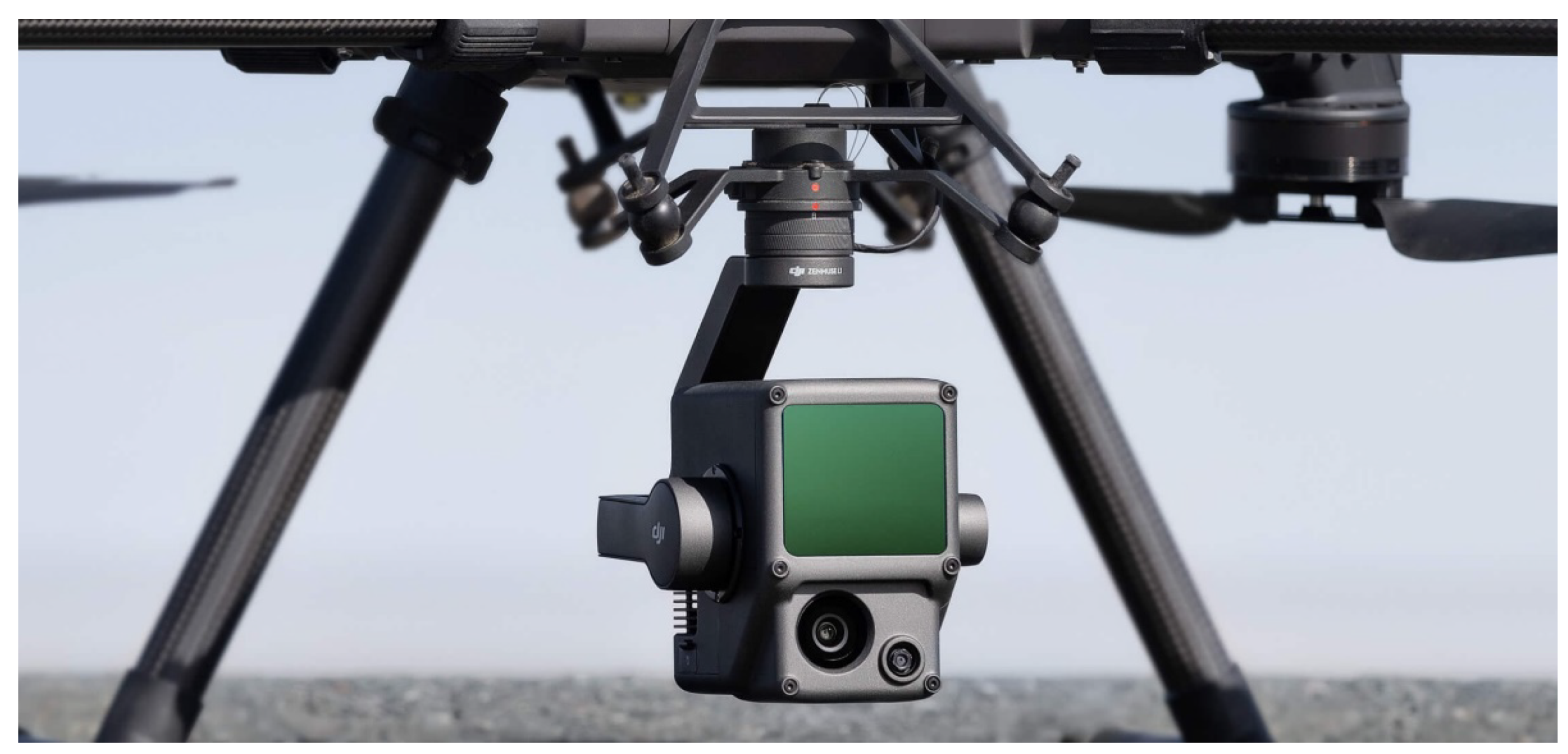
The Zenmuse L1 (Figure 2) is a scanning sensor that integrates a LiDAR module, an RGB camera (not full-frame), and an inertial measurement unit (IMU) (Table 1).
The LiDAR Livox sensor (that supports three returns) is able to detect an effective point rate of about 240 kpts/s on a single return and double that on multiple returns, and the average range is 450 m with 80% reflectivity and 190 m with 10%. It can cover about an average of 2 km2 in a single flight. The RGB camera is characterised by a 20-megapixel CMOS sensor with a mechanical shutter. This LiDAR payload is only supported by the DJI Matrice 300 RTK (real-time kinematic positioning) drone. Further details of the Zenmuse L1 are available on the DJI website [1].

2.2. DJI Zenmuse P1 Description and Accuracy

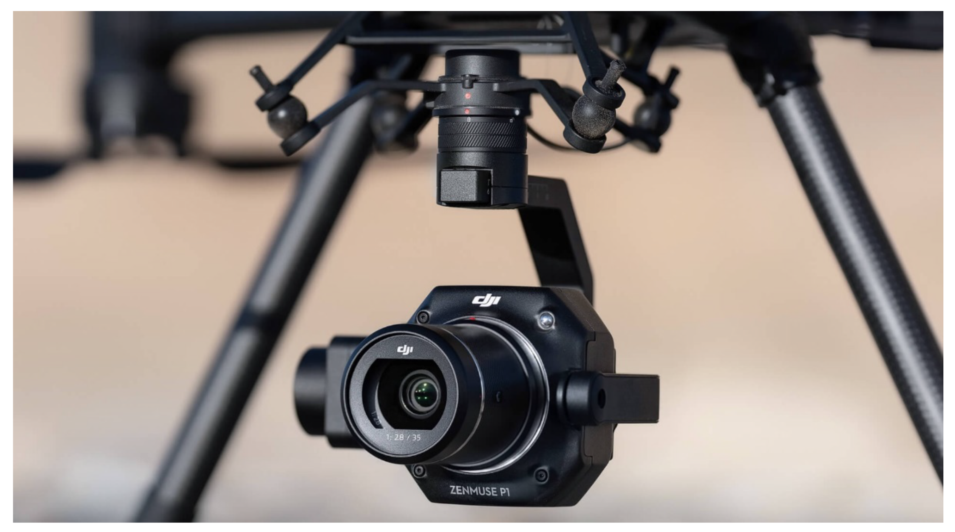
The Zenmuse P1 (Figure 3) represents the new frontier for professional aerial photogrammetry. It is composed of a full-frame sensor that is 35.9 × 24 mm with a mechanical shutter. This photographic payload is anchored to the DJI Matrice 300 RTK drone with a three-axis stabilised gimbal.
This sensor has been designed for professional large-scale photogrammetric projects: in fact, it allows coverage of 3 km2 in a single flight, reaching an accuracy of 0.03 m–0.05 m without GCPs (ground control points). The P1 camera can be equipped with three fixed-focus lenses: 24 mm, 35 mm, or 50 mm. For this survey and project, the 35 mm has been tested. Thanks to the stabilised gimbal, the Zenmuse P1 can obtain smart oblique (off-nadir) captures by automatically rotating the camera at the desired angle: this feature permits achieving in a single flight both nadiral and oblique pictures. The P1 camera includes a global navigation satellite system (GNSS) sensor for spatial positioning. Further details of the Zenmuse P1 can be found on the DJI website [1] and in Table 2.

3. Metric Acquisitions, Data Accuracy and Processing

3.1. Metric Acquisitions: Trimble SX10 and UAS Flights

Metric surveys of the castle started with terrestrial acquisition by using the Trimble scanning station SX10: the Trimble multi-station (MS) can achieve an accuracy of 1 mm + 1.5 ppm by using prisms and 2 mm + 1.5 ppm in DR mode. In addition to total station (TS) features, the SX10 also has a LiDAR sensor incorporated, thus acting as a TLS: the sensor is based on the time of flight (TOF) of laser beams (Trimble Lightning technology). Moreover, the SX10 has a camera sensor of 5 megapixels (not full-frame). Further details of SX10 are available the on Trimble website [2].
The topographic network, inscribed inside a global coordinate system, has been set to achieve a metric accuracy of a few millimetres. This framework has been designed according to established control points inside and outside the castle. This survey has been connected to 8 GNSS points.
The scanning phase with a TOF sensor has been designed in order to cover the entire area of the castle (Figure 4): external (accessible areas) and all internal spaces (one point every 2–6 mm). However, this analysis and manuscript will focus only on the external metric data due to point coverage.
The metric survey continued with UAS flights for the purpose of acquiring data on the upper parts of the castle and integrating the TLS scans. Two flights were undertaken. Both flights were planned and carried out using the DJI Matrice 300 RTK drone [1], which supports the Zenmuse L1 and P1 sensors. UAS flights were performed by HighPix company [17]. The flights covered the entire area of the castle and the surroundings, obtaining a complete dataset.

3.2. Zenmuse L1 Data and Accuracy

The L1 survey generated LiDAR point clouds (Figure 5) managed in the LAZ format. Point clouds were directly georeferenced using the RTK sensor of the Matrice 300. These 3D data are sparse on vertical surfaces (walls) and denser on horizontal planes (ground and roof). This is the result of the Zenmuse L1 flight planning, designed only in nadiral way. However, scattered point clouds resulting from the L1 are also caused by a normal issue of laser beams in motion. Thus, the resulting L1 point clouds are noisy and sparse (with high distance isolated points), and some portions of the building were not covered well.

3.3. Zenmuse P1 Data Processing and Accuracy

The UAS survey with the P1 payload sensor produced 477 total images. The Zenmuse P1 flight was planned to be nadiral and oblique. The obtained data were processed and managed by using the Agisoft Metashape software [18] based on SfM (structure for motion) algorithms.
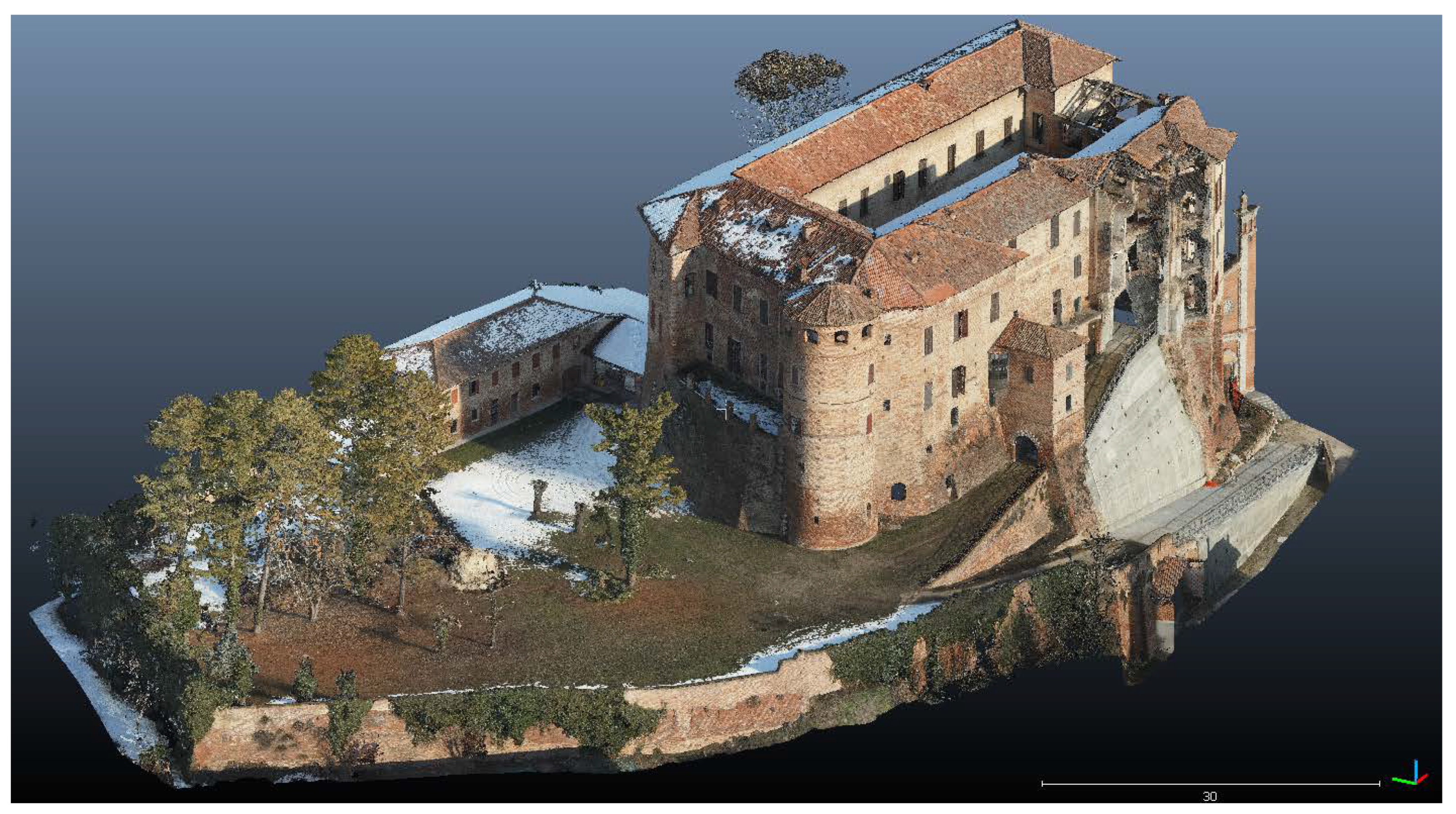
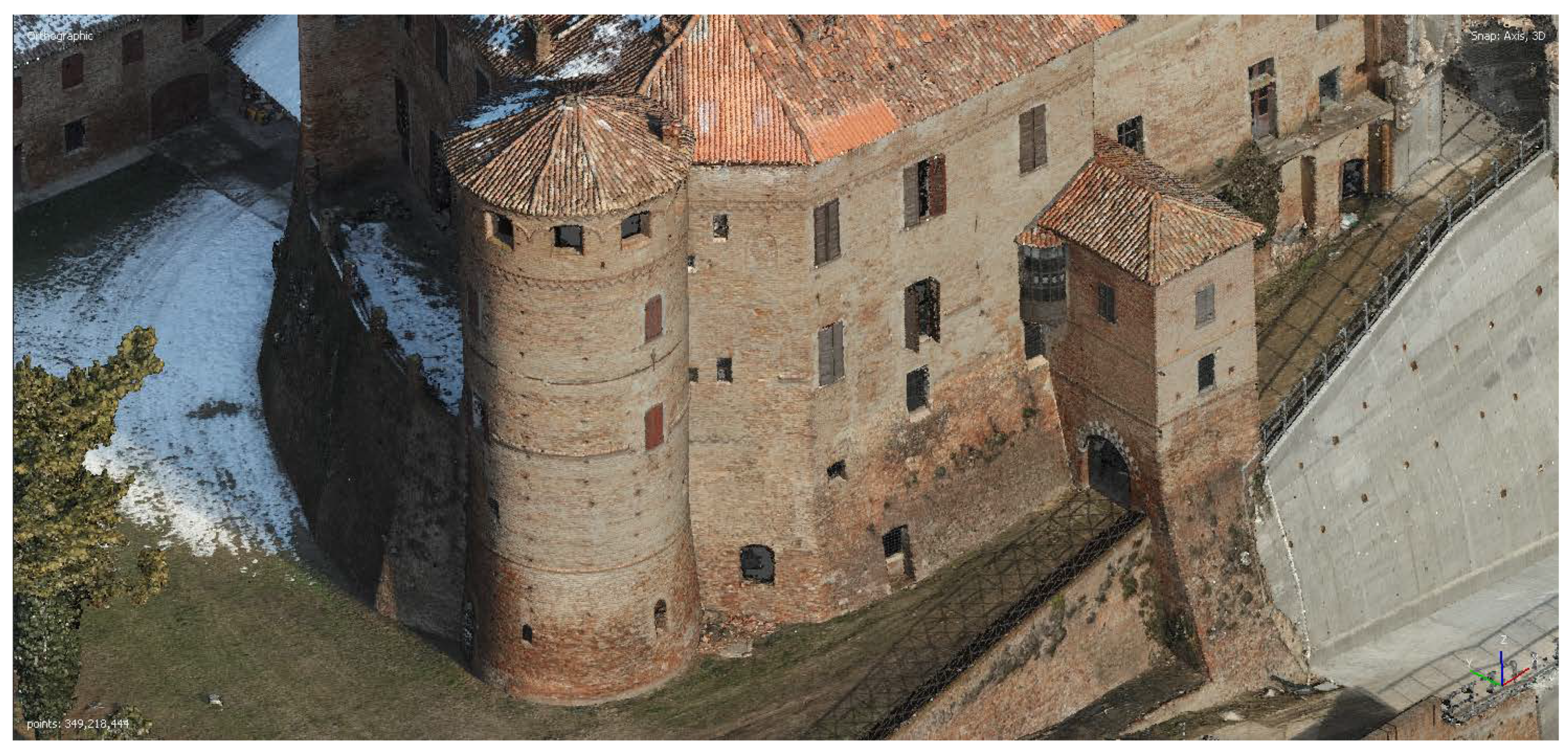
The photogrammetric process included all images captured by the P1 sensors: 477 total images, 336 oblique and 141 nadiral (Figure 6). Within the software, the SfM workflow started with image matching and the following homolog point detection (tie points). The next automatic step was focused on the external orientation by performing bundle block adjustment. Consequently, the dense clouds were created by setting high-quality parameters: this process allows the obtainment of high-density point clouds (about 350 million points) of the entire castle and the surrounding area (Figure 7 and Figure 8).
Nadiral and oblique flights allow the obtainment of dense point clouds related to vertical and horizontal surfaces. The photogrammetric process returned defined surfaces and building components. The P1 data (oriented inside the system to WGS 84/UTM Zone 32N + EGM2008) was also used for creating a high-quality digital elevation model (DEM) and orthophoto with a GSD of 1 cm/pixel. More details of the photogrammetric process can be found in Table 3 and Table 4.

4. Metric Evaluation and Statistical Analyses of Point Clouds

The acquired metric data was handled and analysed through a cloud manager software: the CloudCompare free and open-source software.
Three types of analyses were conducted: ICP alignment; cloud-to-cloud distance (C2C); and roughness analysis. The former tool is based on an automatic fine registration of point clouds or polygonal meshes. To use this tool (for entities roughly registered or having the same shape), an entity reference and a registered one must be set. Following that, editable parameters are the final overlap percentage and scale adjustments, as well as rotation and translation on the x, y, and z axes [12]. C2C distance is a tool for computing distances between two point clouds depending on a compared and a reference cloud. Despite this tool allowing the setting of a custom distance, it is suggested to maintain the automatic calculation. Following that, local modelling options allow for computing and estimating real distances based on a number of neighbours or depending on a spherical neighbourhood. At the end, the computation generates scalar field results [12]. Finally, roughness analysis is a computation of uneven/irregular geometric features of specific entities. It is based on the creation of a hypothetical sphere (editable on its radius) centred on each point and a best-fitting plane computed for neighbouring points [12].
In particular, specific parts of the building were considered for quality assessment. Point clouds of the circular tower of the castle (connecting the east and west sides of the building) were considered for cloud-to-cloud (C2C) analyses and alignment via the ICP algorithm. Both analyses (well consolidated) are extremely fundamental in order to compare and validate different outputs from different sensors [9,10]. Moreover, this data was the focus of a roughness and noise analysis.
ICP registration and alignment were also computed for three profiles of the castle and the surroundings (on the x, y, and z axes), in order to establish reliable root-mean-square errors (RMSe) and cloud translations.
Lastly, brief analyses of radiometric values and the captured vegetation (especially the trees next to the west side of the castle) were performed.

4.1. The Analysis of the Tower of Frinco Castle

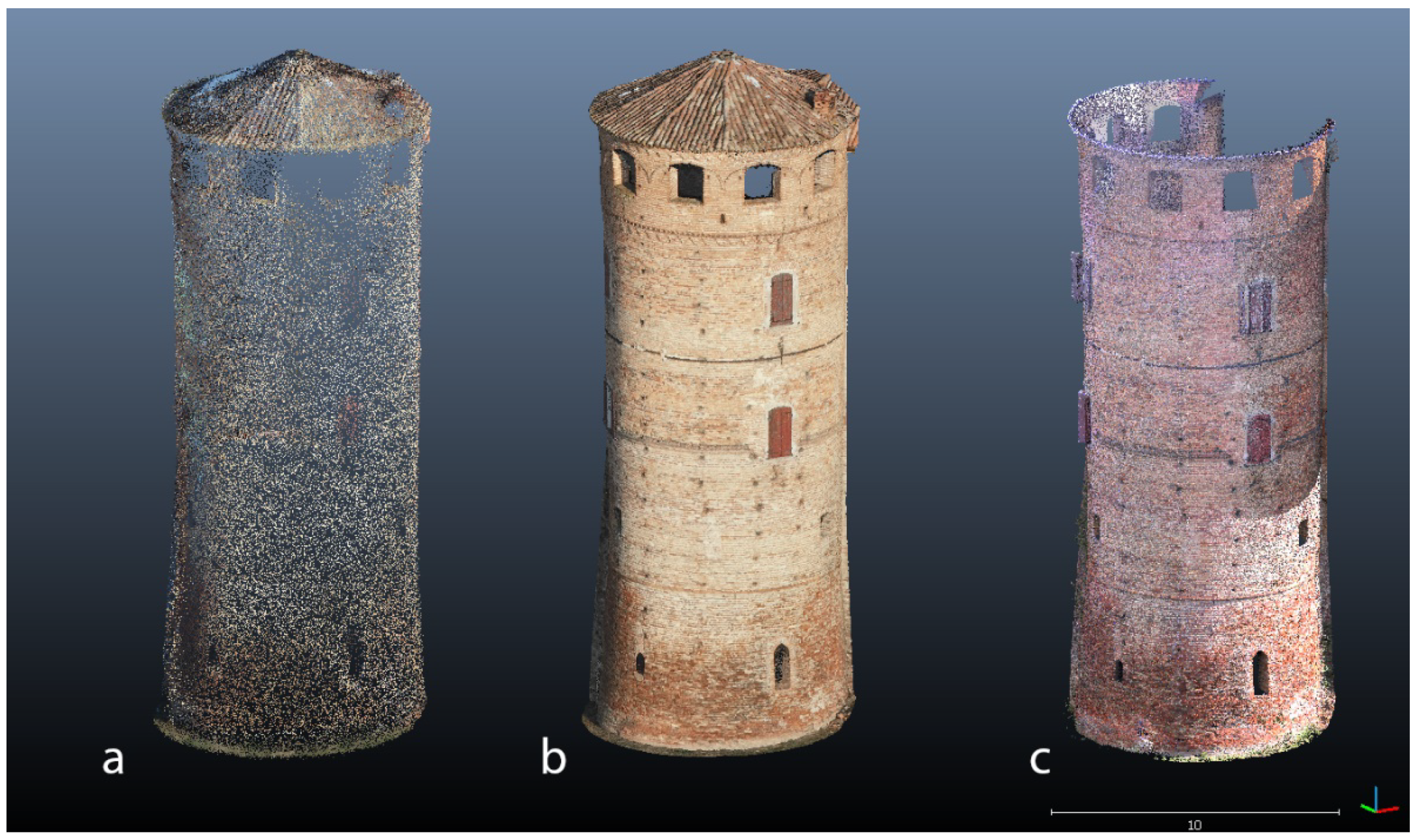
Point clouds related to the circular tower (located in the southwest part of the structure) were cleaned of noisy points and then segmented by following a rectangular selection. Moreover, the comparison of aerial data with the SX10 point clouds was designed by removing the 3D data referring to the roof of the tower from the L1 and P1 (not acquired by the SX10). In this way, the same coverage area of points was examined for a more reliable analysis: in fact, by leaving unmodified the roof data, the CloudCompare software automatically removed uncommon points from the C2C distance computation. However, the roof point clouds were considered for the C2C distance analysis between the L1 and P1 data. Thus, the same portion of the building has been delineated in all metric outputs (Figure 9).
Describing the obtained records, the L1 data shows more scattered point clouds: in fact, surfaces and planes reached by the laser are insufficiently defined and show architectural gaps. By contrast, the photogrammetric point clouds and SX10 data have more geometric accuracy than the L1 data, and architectural elements and building features are well reconstructed (Figure 9 and Table 5).

4.1.1. Cloud-to-Cloud Distance (C2C)

This analysis was performed for the purpose of calculating the average distance between point clouds derived from the UAS and the TLS data obtained from the SX10 scanning station. Terrestrial laser data was chosen as a reference for both analyses because it shows more reliable topographic measurements. Point clouds related to the roof (P1 and L1) were deleted and cleaned in order to obtain optimised data for the analyses with the terrestrial data of SX10, also because the latter was set as reference.
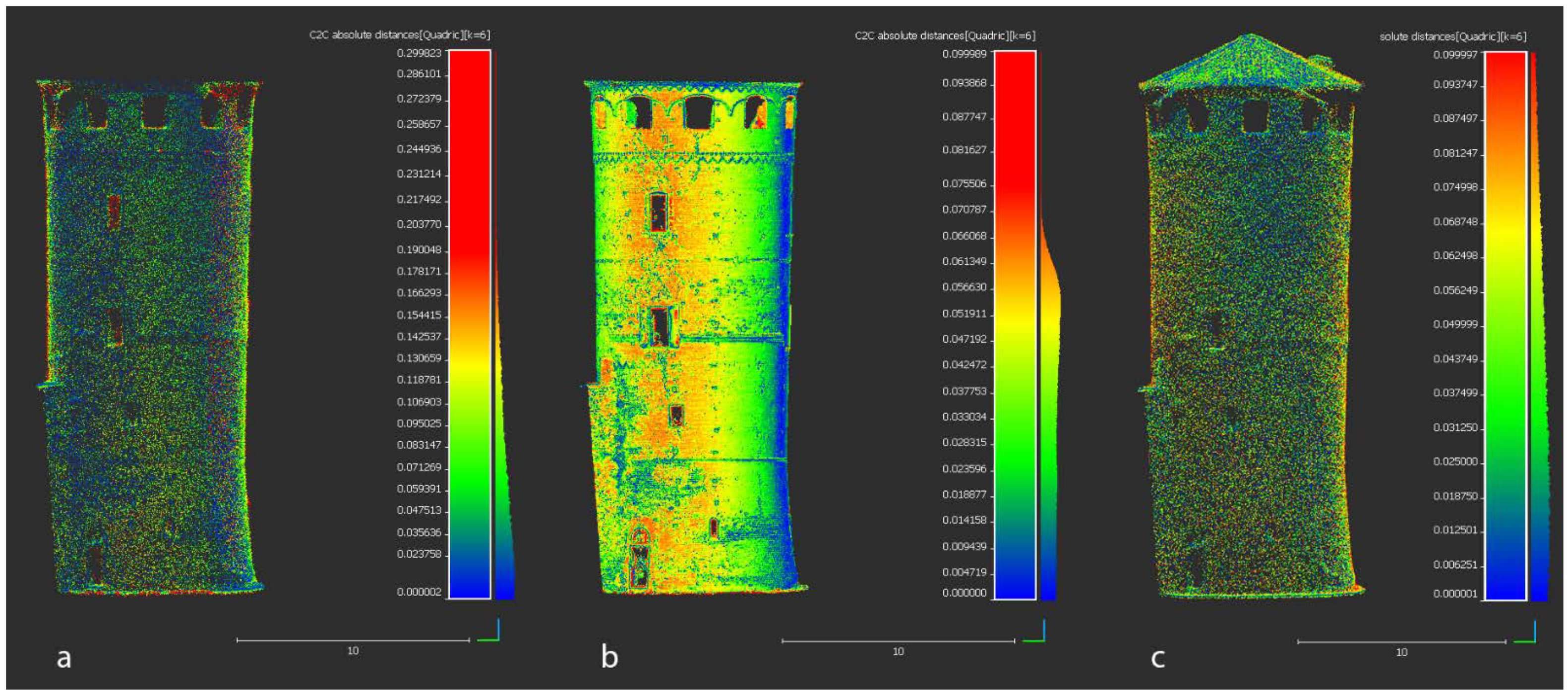
The first calculated distance refers to the variance between the LiDAR L1 data and the TLS data. Using the TLS data as a reference, a quadric local model was constructed with 6 points of k-nearest neighbours (KNN algorithm). The maximum distance was left unchanged (automatic), and then a customised point cloud was extracted (74,238 points) by using a point-filtering tool and setting a range of between 0.0 and 0.3 m. Following that, the software calculated a standard deviation of 0.089 m and a mean distance of 0.076 m (Figure 10a).
Next, the C2C distance is based on the range between the photogrammetric data derived from the P1 sensor (and the Metashape process) and the SX10 point clouds which are used as reference. By filtering data between 0.0 and 0.1 m, the software calculated (also by setting KNN to 6 points) a standard deviation of 0.119 m and a mean distance of 0.044 m on a point cloud of 1,220,153 points (Figure 10b).
Lastly, another C2C distance was established by estimating the variance of the L1 data from the photogrammetric output (set as a reference). In this case, point clouds related to the roof were considered in the computation. Within the filter-by-value tool, the maximum distance was set at 0.1 m in order to facilitate the software recognizing most of the L1 points (sparse clouds). The extracted clouds (113,165 points) were considered for C2C analysis. KNN was set to 6 points. The software then computed a standard deviation of 0.061 m and a mean distance of 0.054 m (Figure 10c). C2C analyses computed with CloudCompare can be observed in Figure 10 and Table 6.
Ranges of distances of the performed estimations have been exported as CSV datasheets and statistically analysed. Details on points coverage related to distances are reported in Table 7, Table 8 and Table 9.

4.1.2. ICP Fine Registration and Alignment

The alignment through fine registration was performed for the L1 and P1 point clouds. Both clouds were aligned to the TLS data (used as static reference). In fact, by using the fine registration tool inside CloudCompare, based on the iterative closest/corresponding point (ICP) algorithm, both clouds were automatically aligned depending on shapes and similarity (without GCPs).
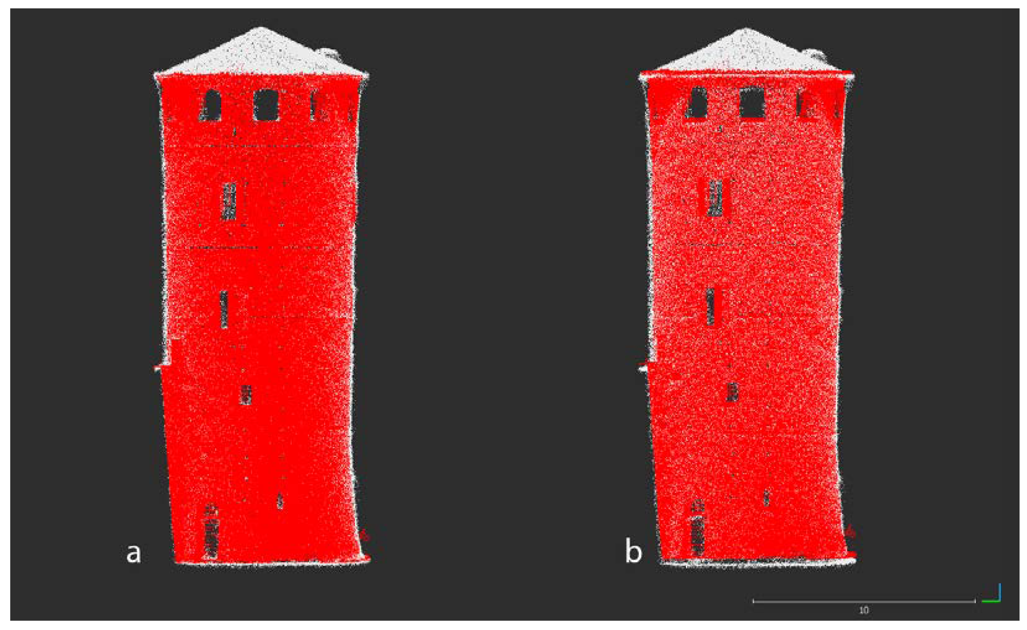
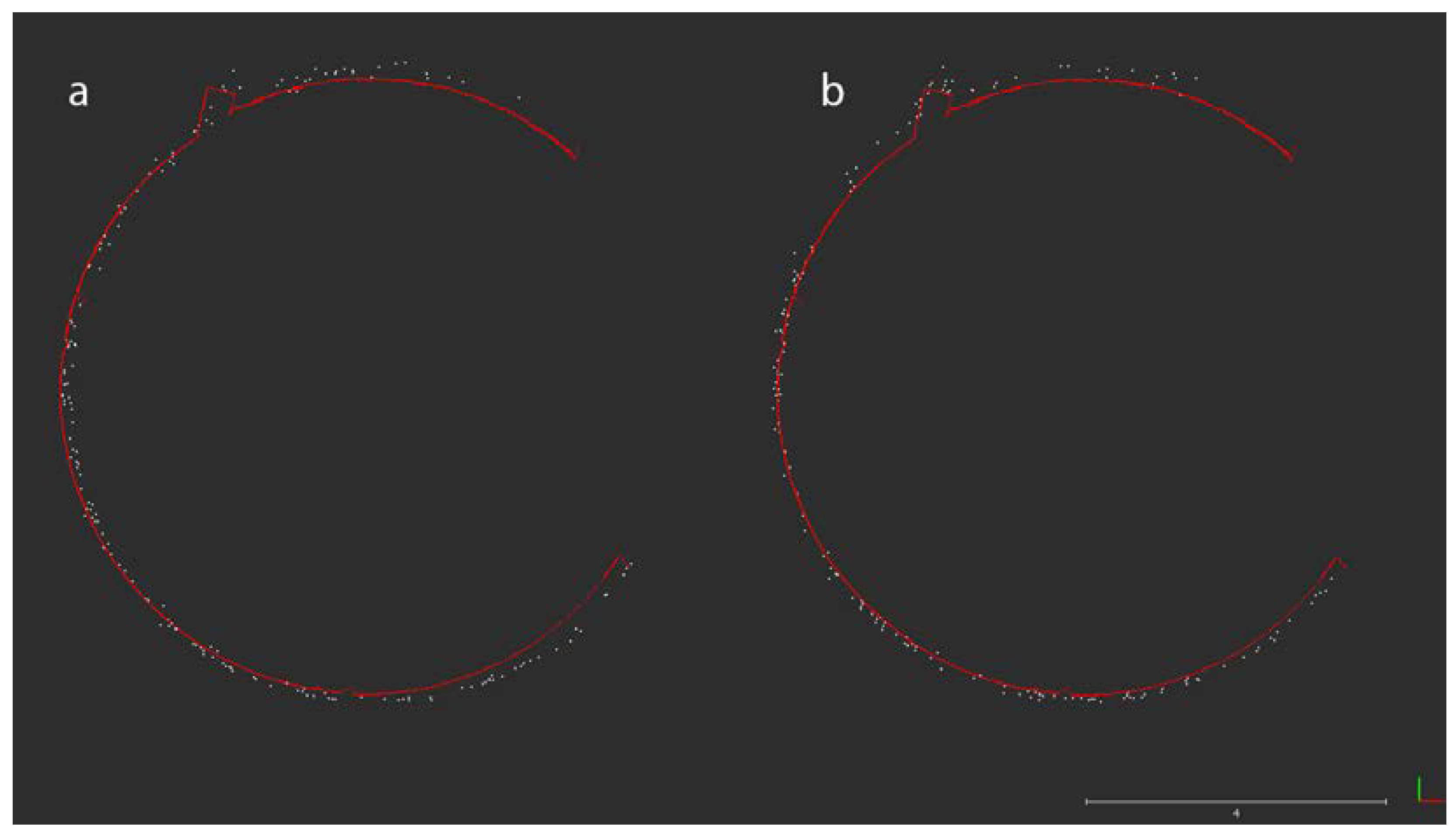
The P1 data registration started by setting the terrestrial clouds as a reference on which to align the photogrammetric clouds. The theoretical overlap was set to 70%, and the removal of the farthest points was enabled. Rotation was enabled only for the z axis. After the process, the software showed these results: RMSe was 0.052m; translation adjustments on x, y, and z were −0.057, 0.018; 0.006 (Figure 11 and Figure 12). The process involved 49,999 total points.
The next alignment process regarded the L1 data being aligned to the TLS clouds. Within the settings, the same overlap was established (70%), as was z rotation. However, the removal of the farthest points was disabled due to the sparse clouds of the L1 data. In this way, the software also considered distant points. By processing 49,999 points, the software estimated a final RMSe of 0.199 m and translations on x of −0.101, y of 0.036, and z of −0.199 (Figure 13 and Figure 14).
The results of both analyses can be observed in Table 10.

4.1.3. Profile Analyses

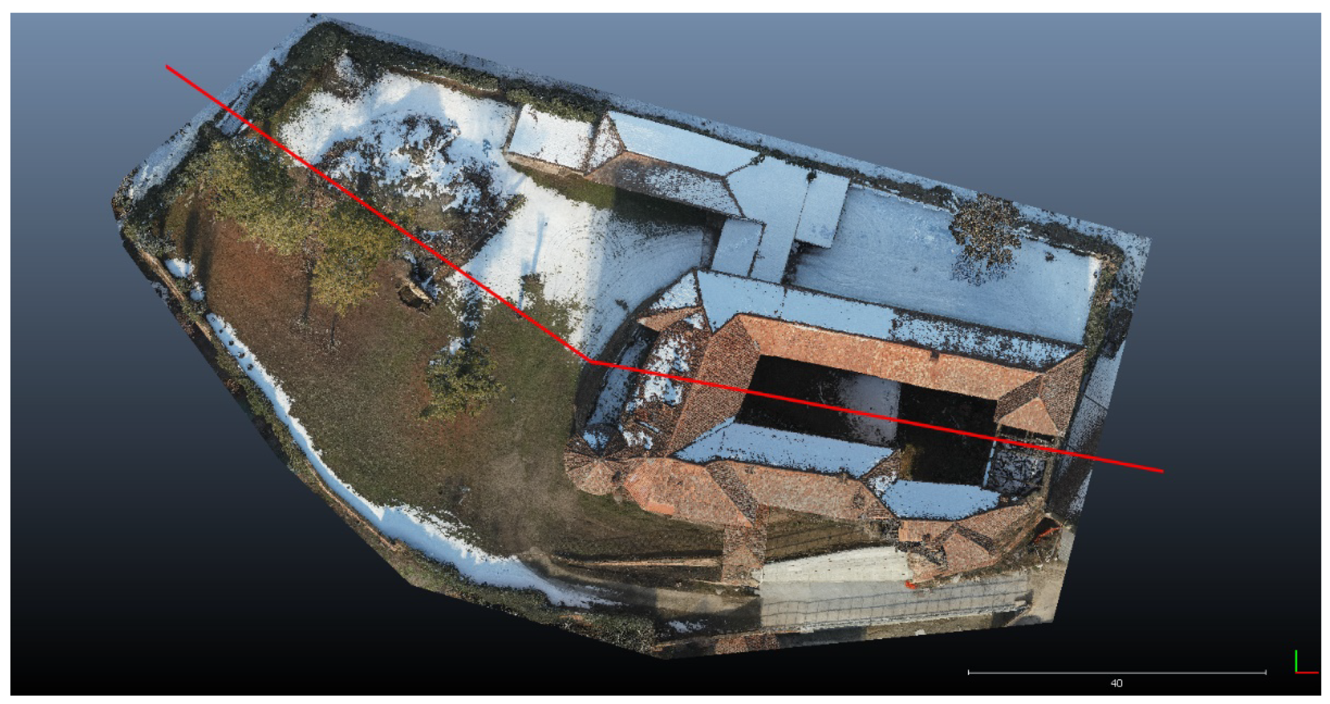
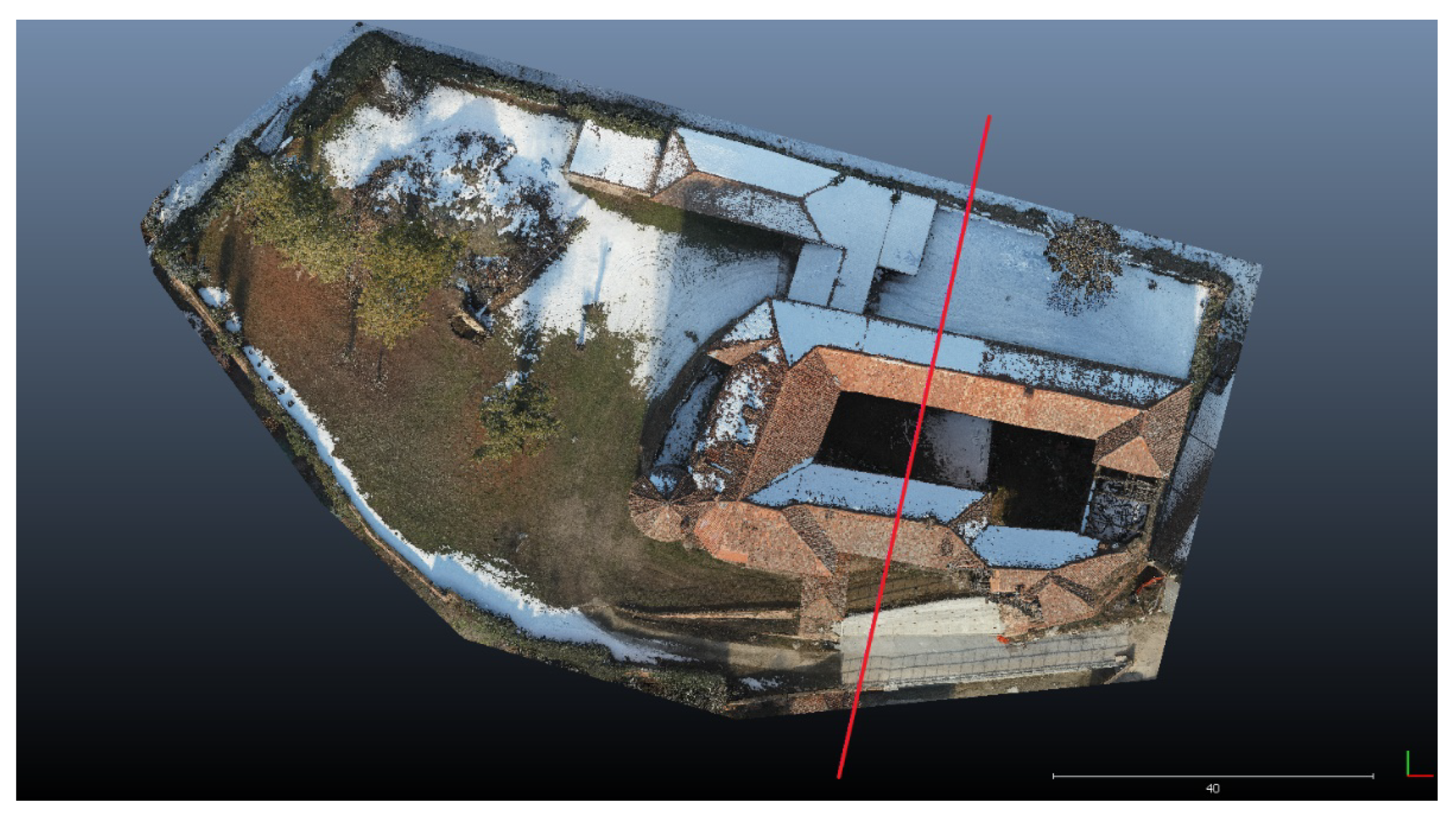
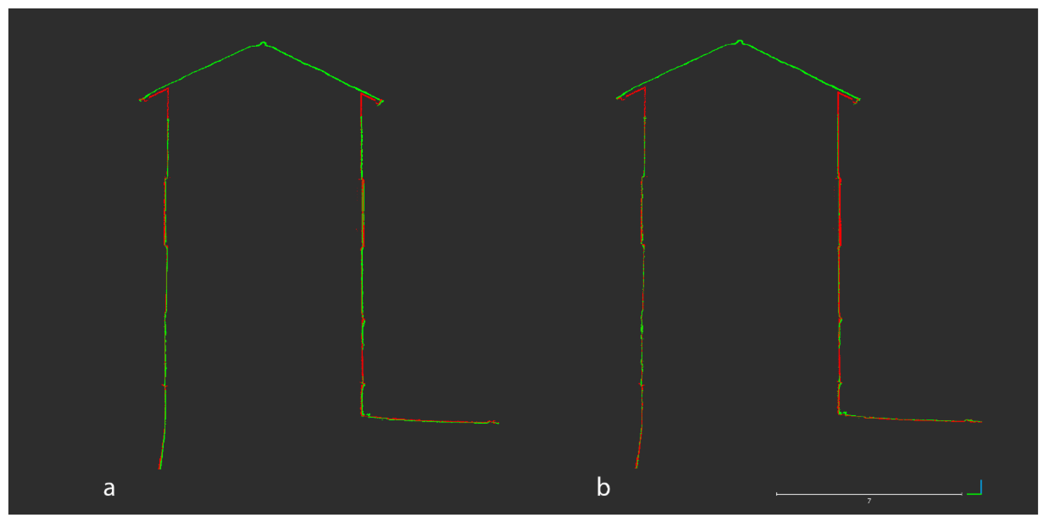
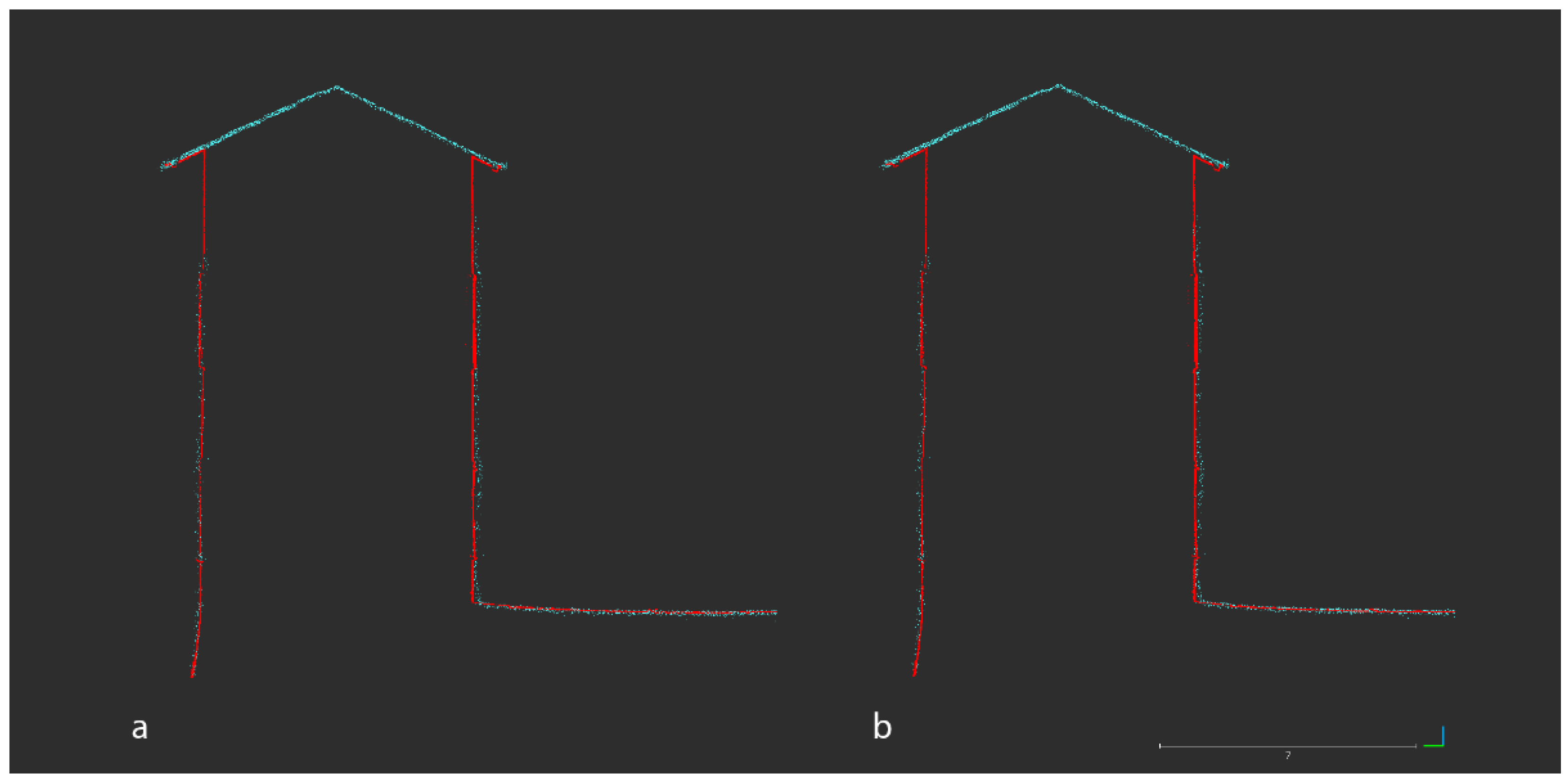
Point clouds related to the castle were analysed and registered also concerning custom profiles created by sectioning 3D data on the x, y, and z axes. This approach was carried out for the purpose of performing different cloud alignments via the ICP algorithm (keeping the TLS data as a reference). Three sections were designed in order to consider the architecture of the castle as well as the ground. The first profile includes the west and the east wings, the internal courtyard of the castle, and the terrain on the west side (Figure 15); the second profile includes the northern and southern wings of the castle, passing through the courtyard (Figure 16); the last profile refers to a vertical section of the entire castle placed 11.50 m from the ground (Figure 17). The obtained profiles have different point densities and placements, depending on scan acquisitions and also on processing (Table 11).
Vegetation and other noisy elements (distant points) were removed from each profile (inside the render space) in order to obtain clean scenes on which to perform analyses.
The first extracted custom profile (Figure 18) was designed to include the ground (on which are placed trees) and the castle (the west and east wings and the internal courtyard). The profile was designed to have a thickness value of 0.2 m.
The registration and alignment started with the P1 data (Figure 19). The photogrammetric data was aligned with the SX10 data, set as reference. The ICP process was customised by setting a theoretical overlap of 70%; the removal of the farthest points was enabled. The software computed a final RMSe of 0.023 m by considering 24,156 points (points limit 50,000); translations were estimated as follows: x −0.061; y 0.015; and z 0.021.
The second alignment is based on the L1 data (Figure 20). The TLS data were set as a reference. The theoretical overlap was regulated at 50%; the removal of the farthest points was enabled. The software computed a final RMSe of 0.164 m on 13,727 points (points limit: 20,000); translations were estimated as follows: x −0.011; y 0.003; and z 0.042. Details of the ICP alignment based on the P1 and L1 data can be found in Table 12.
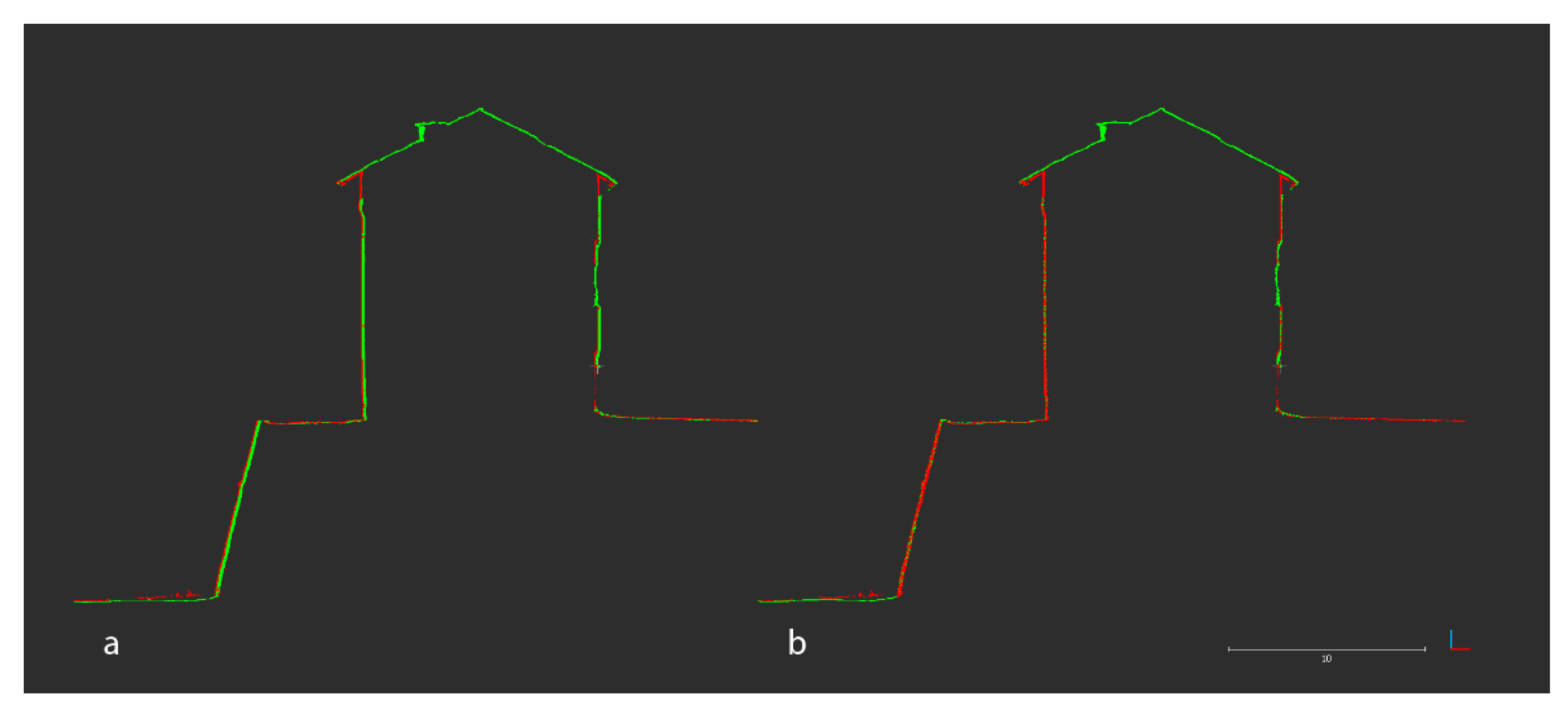
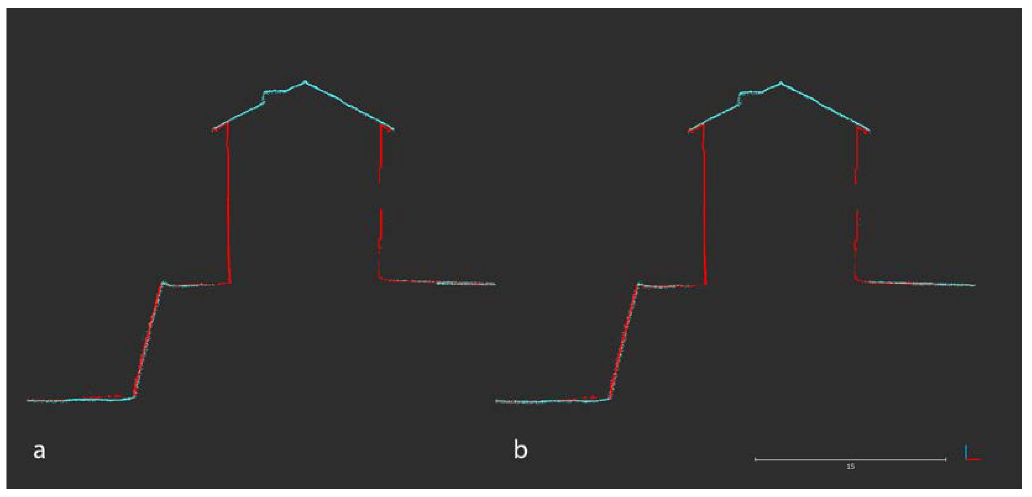
The second profile was designed for sectioning the northern and southern wings of the castle, passing through the internal courtyard. It has a thickness of 0.2 m and also includes a terrain portion of the north side of the castle (Figure 21).
The registration and alignment of the second profile started from the P1 data (Figure 22). Point clouds obtained from the Metashape process were aligned with the terrestrial data (reference). The ICP process was customised by setting a full theoretical overlap of 100%; the removal of the farthest points was enabled. The software computed a final RMSe of 0.014 m by focusing on 41,469 points (points limit: 90,000); translations were estimated as follows: x 0.000; y 0.023; and z 0.030.
The other alignment is related to the LiDAR L1 sensor (Figure 23). The TLS data was set as a reference. The theoretical overlap was set at 60%; the removal of the farthest points was enabled. The software computed a final RMSe of 0.072 m on 7588 points (points limit: 20,000); translations were estimated as follows: x 0.011; y 0.034; and z 0.019. Details of the ICP alignment based on both sensors can be found in Table 13.
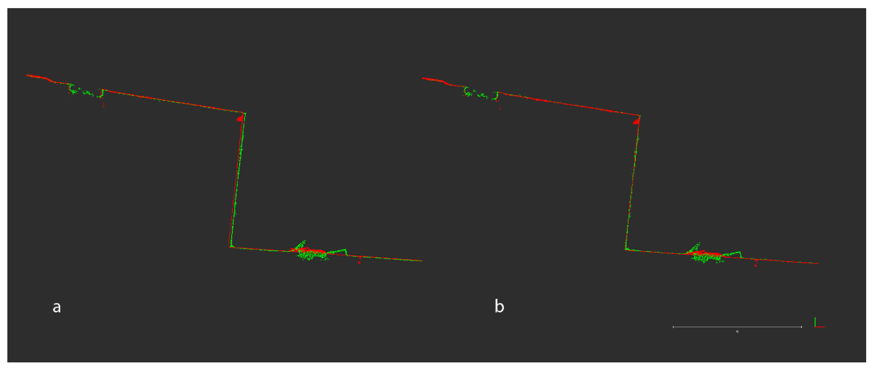
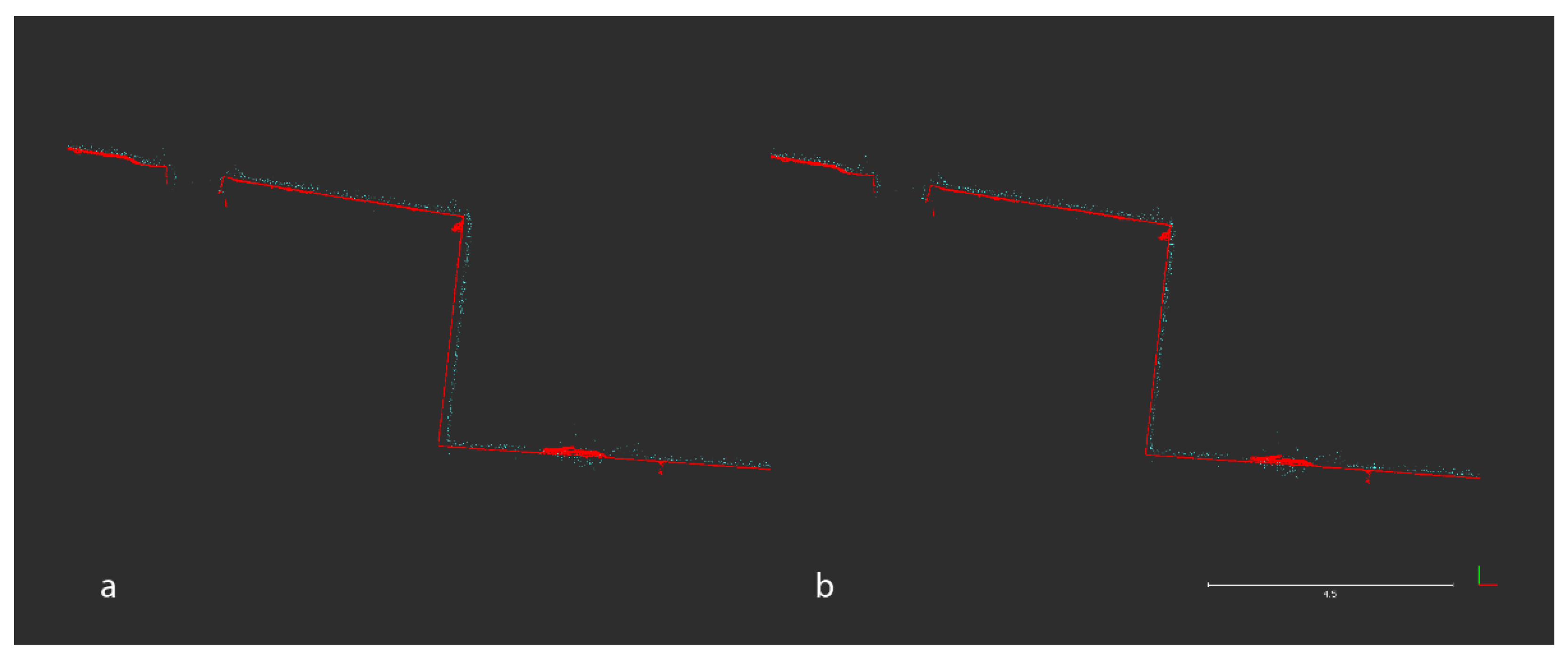
The last profile was obtained using the vertical z axis. It was drawn at 11.50 m from the ground, including the entire perimeter of the castle (also the collapsed area). Furthermore, it was designed to include only the castle, and it has a thickness value of 0.2 m (Figure 24).
As in the previous analyses, the ICP alignment started with the photogrammetric data (Figure 25). Point clouds from the P1 sensor were aligned with the terrestrial data from the SX10 (reference). The theoretical overlap was set at 100%; the removal of the farthest points was enabled. The software then calculated a final RMSe of 0.023 m on 66,468 points (points limit: 90,000); translations were computed as follows: x −0.057; y 0.024; and z 0.001.
The last alignment is related to the L1 sensor (Figure 26), using the SX10 data as a reference. The theoretical overlap was set at 100%; the removal of the farthest points was disabled. The software computed a final RMSe of 0.148 m based on 9528 points (points limit: 20,000); translations were estimated as follows: x −0.071; y 0.029; and z −0.009. Details of both analyses are explained in Table 14.

4.1.4. Roughness Analysis of the Tower

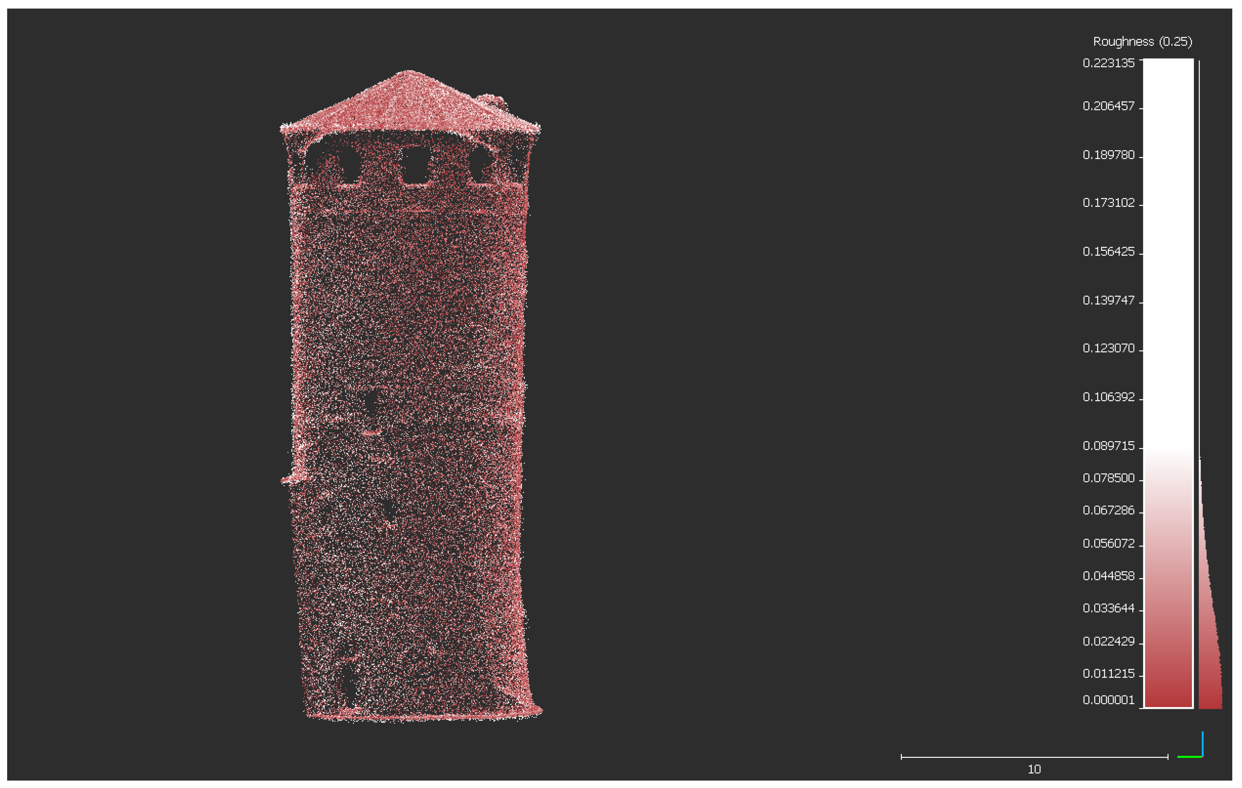
A roughness analysis was conducted to understand the average noise level related to the point clouds of the tower of the castle and uneven points compared to regular surfaces. This step was carried out by using the compute geometric feature tool of CloudCompare. This instrument enables calculation of the roughness level in the x, y, and z directions depending on a local neighbourhood radius: this property was set at 0.1 m for the photogrammetric and TLS point clouds, and 0.25 m for the L1 LiDAR sparse cloud. Consequently, standard deviations of the noise/roughness level were obtained (Figure 27, Figure 28 and Figure 29; Table 15).

4.2. Radiometric Values Analysis

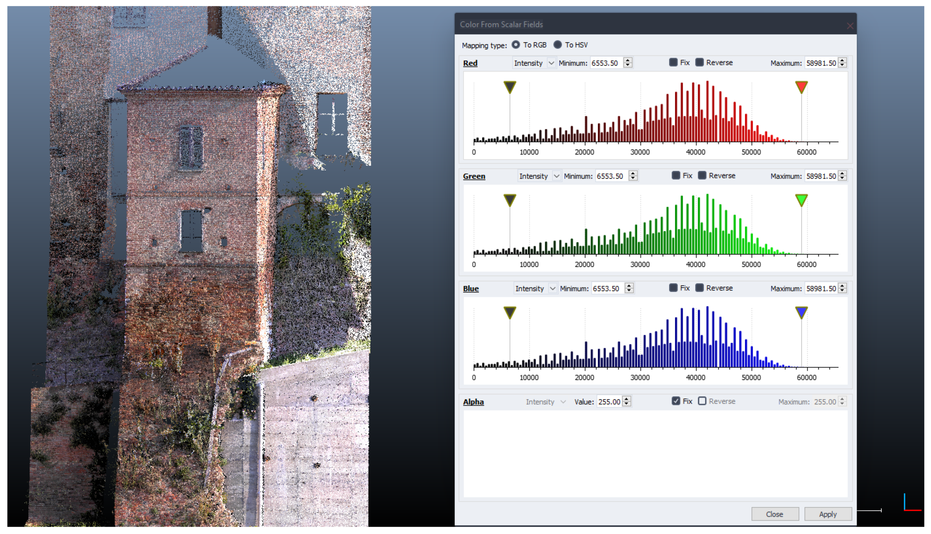
The point clouds also show differences in radiometric values. Analysing the entrance tower of the castle, 3D data obtained from the Trimble scanning station is darker, with more contrast and a cold hue. By contrast, the L1 sensor and the P1 full-frame sensor were able to get lighter and more faithful colours: the radiometric spectrum has a uniform dispersion and warmer intensity. This difference can be seen in Figure 30 and Figure 31, which show red, green, and blue values and intensity related to point clouds.

4.3. Vegetation Short Analysis

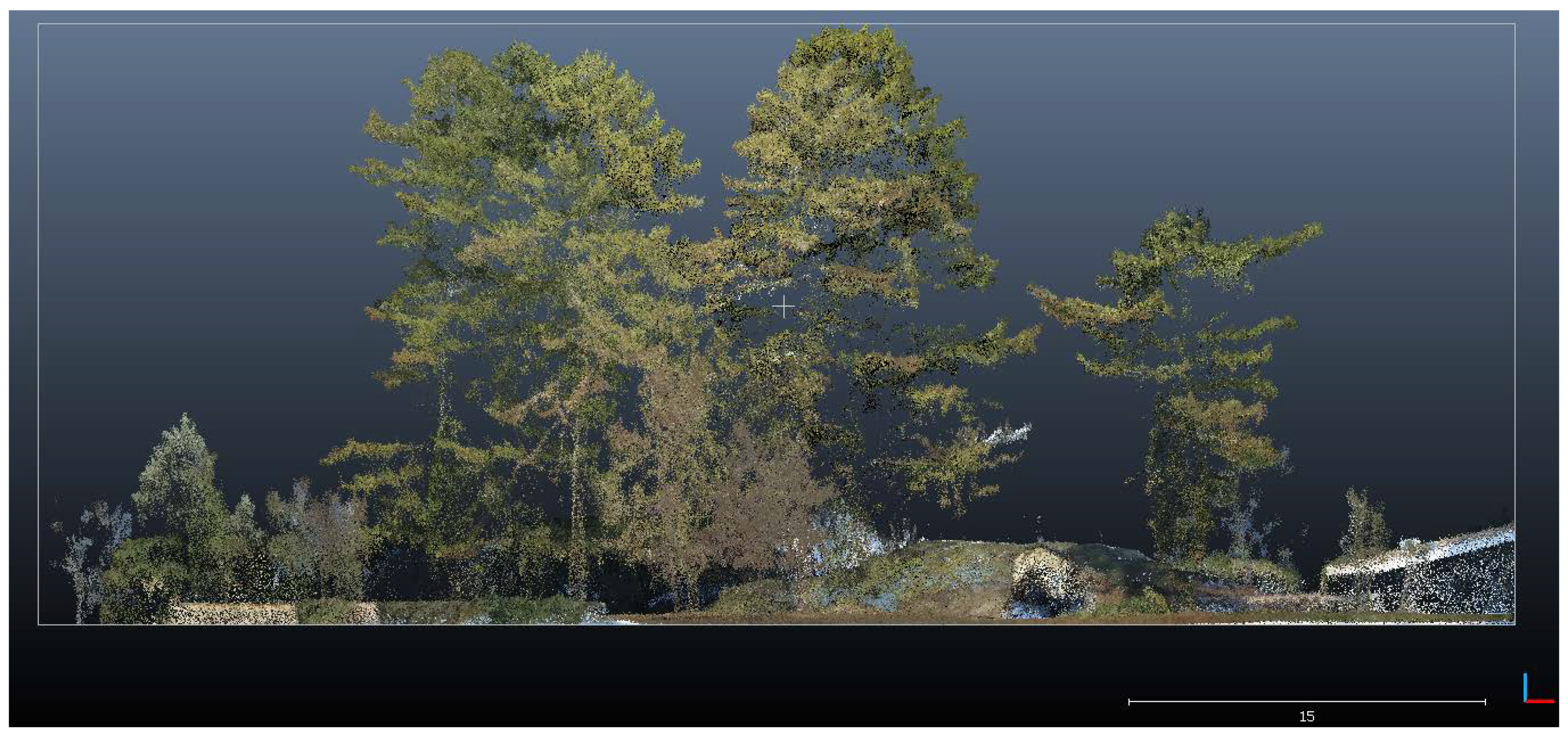
Analysing the vegetation around the castle, the L1 data show a good density and depth of points related to the trees (Figure 32). Although the drone performed only a nadiral flight, the laser was able to penetrate well into the foliage. In fact, airborne LiDAR acquisitions are reliable strategies also for forest, tree, and crop mapping, keeping high levels of detail [19,20,21].
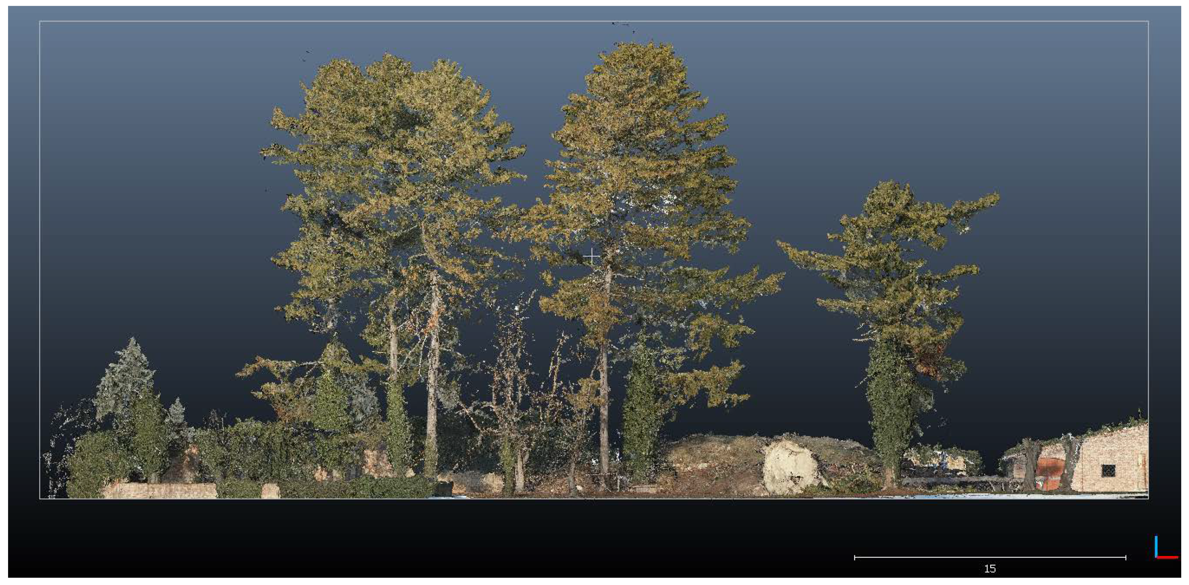
However, a more satisfactory result is given by the P1 sensor and photogrammetric process, which comprehensively reconstructed all of the vegetation details (Figure 33). In fact, aerial photogrammetry (thanks to updated new sensors) is becoming more and more important for landscape- and vegetation-monitoring operations [22]. As expected, the TLS data partially reached the highest foliage of the trees next to the castle, and the colour mapping resulted in noise (Figure 34).

5. Results

The cloud-to-cloud distance analyses of the circular tower generated interesting results (Figure 35). Firstly, the L1 data were compared with the SX10 data, and the software computed a standard deviation of 0.089 m and a mean distance of 0.076 m. By analysing the exported results (range from 0.00 to 0.30 m), the point coverage appears uniform: 34% of points cover a distance range from 0.00 to 0.04 m; 28% of points cover a range from 0.04 to 0.08 m; 22% of points cover a range from 0.08 to 0.12 m; 16% of points cover a range from 0.12 to 0.30 m. In addition, the L1 record has a mean distance of about 8 centimetres from the TLS acquisitions, also having a uniform distribution of points (even if the clouds are sparse).
The photogrammetric data revealed different results concerning C2C analysis: the software calculated a standard deviation of 0.119 m and a mean distance of 0.044 m. Despite the deviation being about 12 centimetres, the mean distance is set to 4 centimetres. Only the 3% of points cover a range of 0.08–0.10 m, while 35% cover a range of 0.00–0.02 m, and about 60% of points refer to a distance range of 0.02–0.08 m. In addition, the average distance between the P1 and SX10 data is about 0.04 m. Furthermore, centimetric distances were also detected from the L1 to the P1 data: the standard deviation is 0.061 m, and the mean distance is 0.054 m. The points distribution is very uniform between them, being 33% in a range of 0.00–0.02 m; 26% in a range of 0.02–0.04 m; 28% in a range of 0.04–0.08 m; and 13% in a range of 0.08–0.10 m.
The ICP alignment of the tower resulted in an interesting analysis. Regarding the L1 data, they were aligned with the TLS clouds. The CloudCompare software calculated a final RMSe of 0.199 m and the following translations: x −0.101; y 0.036; and z −0.199. The P1 data alignment generated an RMSe of 0.052 m; the translation adjustments on x, y, and z are −0.057, 0.018, and 0.006, respectively. By analysing these results, photogrammetric data were revealed to be extremely accurate and reliable compared with terrestrial acquisitions: in fact, centimetric shifts were calculated among two different outputs, as were millimetric movements on the z axis.
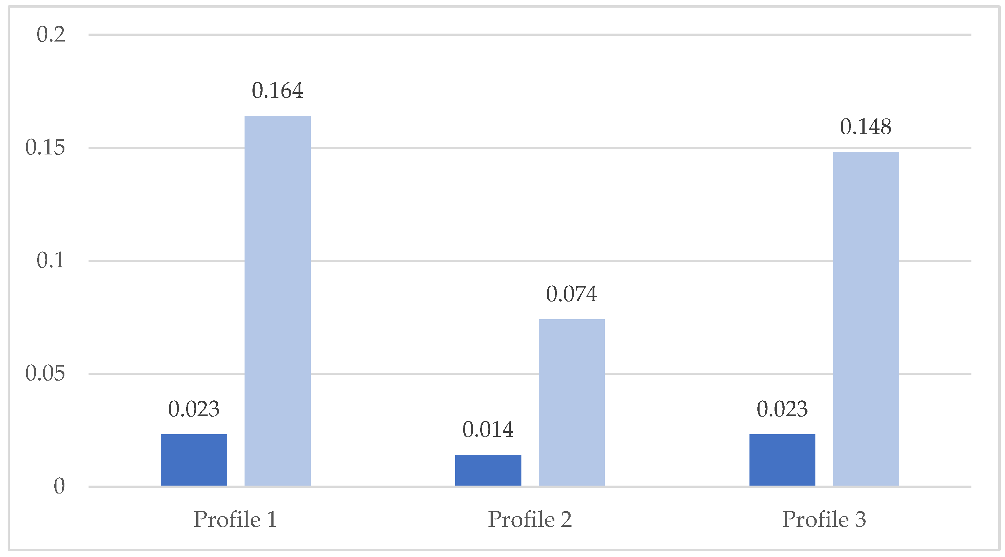
ICP registration and alignment continued with the custom profile analyses. The alignment generated satisfying results. The photogrammetric data show centimetric RMS errors (between 0.014 m and 0.023 m) in all analysed profiles, while L1 data reported an average RMS error of 13 centimetres (Figure 36): the higher value is 0.164 m, and the lower one is 0.074. The alignment of the photogrammetric output to the SX10 data was revealed to be more accurate than the L1 sparse clouds, even if they were almost defined in the ground plan.
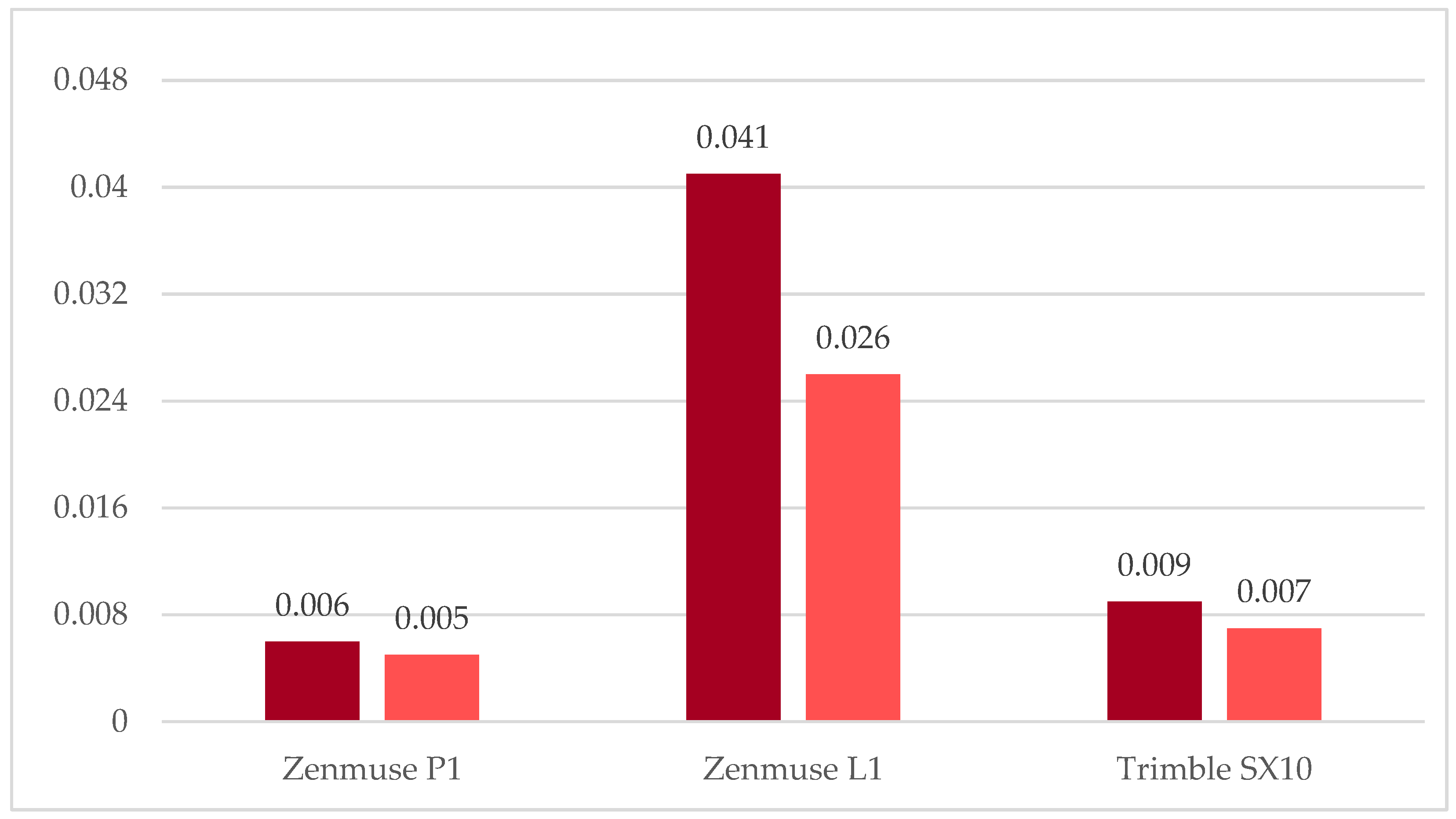
Regarding the roughness analysis, despite the SX10 point clouds being denser and more populated (although not including the roof and upper record), the photogrammetric data are more detailed and accurate on building shapes, while also showing less noise. In fact, the process calculated an RMSe of 0.007 m and 0.005 m of deviation for the P1; an RMSe of 0.047 m and 0.025 m of deviation for the L1; and an RMSe of 0.009 m and 0.007 m of deviation for the SX10 (Figure 37). Surprisingly, the Zenmuse P1 data reported less roughness and noise than the terrestrial acquisitions (even if both are within a few millimetres). As expected, the L1 point clouds were the noisiest, with more roughness around geometric features.
The point clouds also displayed significant differences related to RGB restitution: the 45-megapixel full-frame sensor of the P1 camera was able to process and return faithful colours of the castle and the context (terrain and vegetation), while the L1 and SX10 incorporated cameras (20 and 5 megapixels, respectively, not full-frame sensor) captured more approximate colours. Having LiDAR sensors, the L1 and SX10 also captured more noise and light reflections.

6. Discussion

This work, in addition to being designed to estimate the accuracy of different sensors, was also useful for understanding the possibilities and drawbacks of these instruments.
Being a benchmark and evaluation work, time analysis could be fundamental. Regarding the elaboration time, the photogrammetric process took (as expected) the longest, even though it was not a very time-consuming operation; thanks to a professional workstation (i9-11900K; 128 GB RAM; NVIDIA Quadro RTX 4000), the photogrammetric steps (from bundle block adjustment to dense cloud and mesh generation) took about 3 h (477 pictures processed with high-quality details). The acquisition of aerial pictures took about 25 min, and the same time was required for the L1. In this regard, the time of acquisition and elaboration was not an issue.
The software used for SfM processing was Agisoft Metashape, chosen for its reliability. Despite it is complete and accurate solution, it would be interesting to perform future analyses (by using the same dataset from the P1) with other photogrammetric software which allows advanced and open control of reconstruction steps.
The point cloud management phase (related to the tower dataset and profiles) was not a time-consuming phase, as the segmentation and cleaning processes were very easy to conduct using the CloudCompare software. In fact, both the photogrammetric process and the point cloud acquisitions of the LiDAR sensors generated quite clean outputs with few noise points.
Being extremely accurate and dynamic solutions, the L1 and P1 represent valuable solutions for rapid mapping and surveying. Moreover, structures and formations at risk can be quickly surveyed, reconstructed, and drawn for consolidation and restoration processes with quality and accuracy almost equal to pure TLSs and multi-stations. However, a small note should be made regarding the economic aspect. Despite the actual panorama of aerial payloads being characterised by low-budget instruments [20,21,22,23,24], the L1 and P1 are not low-cost solutions, even if some payload sensors for UAVs/UASs have seen reductions in their prices allowing for new possibilities and strategies in surveying. In fact, in some cases the sensors’ price can be a real drawback for surveys and research, also determining the outcome of projects.

7. Conclusions

The goal of this study was to establish a reliable benchmark and quality assessment related to new sensors used for topographic and architectural surveys—the Zenmuse L1 and P1—compared with terrestrial Trimble SX10 data.
The performed geomatic surveys of the Frinco Castle, within the restoration and architectural enhancement programme, proved to be a pleasing chance to test and evaluate the new sensors. This analysis could facilitate the integration process between different three-dimensional outputs depending on architectural features and scan coverage. UAS and TLS approaches allow for the obtainment of point clouds with an accuracy of a few centimetres.
The performed analyses are helpful for understanding the quality and accuracy of different sensors. As also confirmed by other studies [11,14,15], the L1 and P1 analysis revealed a reliable solution for the purpose of designing an integrated survey. In particular, this integration is extremely fundamental for complex and large-scale structures, e.g., the Frinco Castle.
Despite the L1 data seeming to be sparse and less populated than other datasets, L1 point clouds can be also used (with centimetric precision) for architectural representation (e.g., 1:200). In fact, by sectioning L1 data, it is possible to extract completed profiles of the castle (as seen in the profile analysis). However, the obtained results confirmed that terrestrial and photogrammetric data are significantly superior for the restitution of external architectural elements of the castle (e.g., detailed decorations of the tower). In particular, the photogrammetric output shows outstanding results: acquired images (nadir and off-nadir) allow the obtainment of a complete point cloud of the castle with high-level details of architectural elements and 1/2 centimetres of precision. The Zenmuse P1 sensor has had and will continue to have a great impact on aerial photogrammetry due to the high-quality specifications of the camera, the stabilization sensors, and GNSS positioning. This new sensor could see wide use for rapid and high-detail surveys.
Roughness analysis confirmed what is possible to visually observe: the L1 dataset is extremely sparse, showing discontinuities and distant points. By contrast, the photogrammetric record seems to have less noise and discontinuity than the SX10 data.
In conclusion, the DJI Zenmuse L1 and P1 currently represent the last frontier of airborne surveys, using to active and passive sensors. At the same time, the SX10 multi-station (and its heir, the SX12) could be the best solution for acquiring terrestrial scans and topographic data in within a short time (which is fundamental for rapid mapping). Both aerial sensors represent valuable and reliable solutions for integrated surveys with centimetric precision and direct georeferencing (IMU/GNSS).
The collected datasets (P1, L1, and SX10) are not redundant, and they integrate with each other, permitting the obtainment of a complete digital backup (or digital twin) of the castle. This possibility is fundamental for the consolidation and restoration project after the collapse of a portion of the south wing. Moreover, the collected outputs could be used as basis for other kinds of documentation processes—for example, historic building information modelling (HBIM) of the castle (obtaining a digital informative twin), which would be useful for monitoring operations as well as collaborative approaches.

Author Contributions

Conceptualization, M.R. and F.D.; methodology, M.R. and F.D.; software, F.D.; validation, M.R. and F.D.; formal analysis, M.R. and F.D.; investigation, F.D.; resources, M.R. and F.D.; data curation, M.R. and F.D.; writing—original draft preparation, F.D.; writing—review and editing, M.R. and F.D.; visualisation, M.R. and F.D.; supervision, M.R. and F.D.; project administration, M.R.; funding acquisition, M.R. All authors have read and agreed to the published version of the manuscript.

Funding

This research was funded by the Fondazione Cassa di Risparmio di Asti.

Institutional Review Board Statement

Not applicable.

Informed Consent Statement

Not applicable.

Data Availability Statement

Not applicable.

Acknowledgments

The authors would like to acknowledge the Frinco Municipality for supporting the topographic and UAS surveys. In this regard, particular thanks go to Highpix company and Enrico Iuliano for performing and supporting the UAS flights for the aerial survey of the Frinco Castle. At the same time, special thanks go to Arch. Eng. Giorgio Viazzo and Arch. Eng. Chiara Viazzo for contributing and supporting the terrestrial acquisition phase.

Conflicts of Interest

The authors declare no conflict of interest.

References

  1. DJI Website. Available online: https://www.dji.com (accessed on 21 June 2022).
  2. Trimble Website. Available online: https://www.trimble.com/en (accessed on 21 June 2022).
  3. Sani, N.H.; Tahar, K.N.; Maharjan, G.R.; Matos, J.C.; Muhammad, M. 3D reconstruction of building model using UAV point clouds. In Proceedings of the International Archives of the Photogrammetry, Remote Sensing and Spatial Information Sciences, Nice, France, 6–11 June 2022; Volume XLIII-B2-2022; pp. 455–460. [Google Scholar] [CrossRef]
  4. Cledat, E.; Skaloud, J. Fusion of photo with airborne laser scanning. ISPRS Ann. Photogramm. Remote Sens. Spatial Inf. Sci 2020, V-1-2020, 173–180. [Google Scholar] [CrossRef]
  5. Ekaso, D.; Nex, F.; Kerle, N. Accuracy assessment of real-time kinematics (RTK) measurements on unmanned aerial vehicles (UAV) for direct geo-referencing. Geo-Spat. Inf. Sci. 2020, 23, 165–181. [Google Scholar] [CrossRef] [Green Version]
  6. Štroner, M.; Urban, R.; Línková, L. A New Method for UAS Lidar Precision Testing Used for the Evaluation of an Affordable DJI Zenmuse L1 Scanner. Remote Sens. 2021, 13, 4811. [Google Scholar] [CrossRef]
  7. Gaspari, F.; Ioli, F.; Barbieri, F.; Belcore, E.; Pinto, L. Integration of UAS-LiDAR and UAS-photogrammetry for infrastructure monitoring and bridge assessment. In Proceedings of the International Archives of the Photogrammetry, Remote Sensing and Spatial Information Sciences, Nice, France, 6–11 June 2022; Volume XLIII-B2-2022, pp. 995–1002. [Google Scholar] [CrossRef]
  8. Nex, F.; Armenakis, C.; Cramer, M.; Cucci, D.A.; Gerke, M.; Honkavaara, E.; Skaloud, J. UAV in the advent of the twenties: Where we stand and what is next. ISPRS J. Photogramm. Remote Sens. 2020, 184, 215–242. [Google Scholar] [CrossRef]
  9. Teppati Losè, L.; Matrone, F.; Chiabrando, F.; Giulio Tonolo, F.; Lingua, A.; Maschio, P. New developments in lidar UAS surveys. Performance analyses and validation of the DJI Zenmuse L1. In Proceedings of the International Archives of the Photogrammetry, Remote Sensing and Spatial Information Sciences, Nice, France, 6–11 June 2022; Volume XLIII-B1-2022, pp. 415–422. [Google Scholar] [CrossRef]
  10. Kersten, T.; Wolf, J.; Lindstaedt, M. Investigations into the accuracy of the UAS system DJI Matrice 300 RTK with the sensors Zenmuse P1 and L1 in the Hamburg test field. In Proceedings of the International Archives of the Photogrammetry, Remote Sensing and Spatial Information Sciences, Nice, France, 6–11 June 2022; Volume XLIII-B1-2022, pp. 339–346. [Google Scholar] [CrossRef]
  11. Peppa, M.V.; Morelli, L.; Mills, J.P.; Penna, N.T.; Remondino, F. Handcrafted and learning-based tie point features—Comparison using the EuroSDR RPAS benchmark dataset. In Proceedings of the International Archives of the Photogrammetry, Remote Sensing and Spatial Information Sciences, Nice, France, 6–11 June 2022; Volume XLIII-B2-2022, pp. 1183–1190. [Google Scholar] [CrossRef]
  12. CloudCompare Software. Available online: https://www.danielgm.net/cc/ (accessed on 21 June 2022).
  13. Bordone, R. Andar per Castelli da Asti Tutt’intorno; Milvia: Torino, Italy, 1976; ISBN 2020010144721. [Google Scholar]
  14. Sorisio, R. Ricerche Storico-Giuridiche su Frinco. Master’s Thesis, University of Turin, Turin, Italy, 1979. [Google Scholar]
  15. Lachat, E.; Landes, T.; Grussenmeyer, P. Investigation of a Combined Surveying and Scanning Device: The Trimble SX10 Scanning Total Station. Sensors 2017, 17, 730. [Google Scholar] [CrossRef] [PubMed] [Green Version]
  16. Lachat, E.; Landes, T.; Grussenmeyer, P. First experiences with the Trimble SX10 scanning total station for building facade survey. In Proceedings of the International Archives of the Photogrammetry, Remote Sensing and Spatial Information Sciences, Nafplio, Greece, 1–3 March 2017; Volume XLII-2/W3, pp. 405–412. [Google Scholar] [CrossRef] [Green Version]
  17. HighPix Company. Available online: https://www.highpix.it (accessed on 21 June 2022).
  18. Agisoft Metashape. Available online: https://www.agisoft.com (accessed on 21 June 2022).
  19. Ramalho de Oliveira, L.F.; Lassiter, H.A.; Wilkinson, B.; Whitley, T.; Ifju, P.; Logan, S.R.; Peter, G.F.; Vogel, J.G.; Martin, T.A. Moving to Automated Tree Inventory: Comparison of UAS-Derived Lidar and Photogrammetric Data with Manual Ground Estimates. Remote Sens. 2021, 13, 72. [Google Scholar] [CrossRef]
  20. Jaakkola, A.; Hyyppä, J.; Kukko, A.; Yu, X.; Kaartinen, H.; Lehtomäki, M.; Lin, Y. A low-cost multi-sensoral mobile mapping system and its feasibility for tree measurements. ISPRS J. Photogramm. Remote Sens. 2010, 65, 514–522. [Google Scholar] [CrossRef]
  21. Zhang, F.; Hassanzadeh, A.; Kikkert, J.; Pethybridge, S.J.; Van Aardt, J. Comparison of UAS-Based Structure-from-Motion and LiDAR for Structural Characterization of Short Broadacre Crops. Remote Sens. 2021, 13, 3975. [Google Scholar] [CrossRef]
  22. Mugnai, F.; Masiero, A. Integrating UAS Photogrammetry and Digital Image Correlation for High-Resolution Monitoring of Large Landslides. Preprints 2022, 2022010248. [Google Scholar] [CrossRef]
  23. Pinto, L.; Bianchini, F.; Nova, V.; Passoni, D. Low-Cost UAS Photogrammetry for road Infrastructures’inspection. In Proceedings of the International Archives of the Photogrammetry, Remote Sensing and Spatial Information Sciences, Nice, France, 14–21 June 2020; Volume XLIII-B2-2020, pp. 1145–1150. [Google Scholar] [CrossRef]
  24. Yordanov, V.; Biagi, L.; Truong, X.Q.; Brovelli, M.A. Landslide surveys using low-cost UAV and FOSS photogrammetric workflow. In Proceedings of the International Archives of the Photogrammetry, Remote Sensing and Spatial Information Sciences, Nice, France, 6–11 June 2022; Volume XLIII-B2-2022; pp. 493–499. [Google Scholar] [CrossRef]
Figure 1. Workflow applied for this project: from metric surveys to point cloud management and analyses.
Geomatics 02 00015 g001
Figure 2. Zenmuse L1 LiDAR sensor, anchored to a gimbal and a DJI Matrice 300 RTK drone (image from www.dji.com accessed on 10 July 2022).
Geomatics 02 00015 g002
Figure 3. Zenmuse P1 sensor equipped with the 35 mm lens: the camera is anchored to the gimbal and the DJI Matrice 300 RTK drone (image from www.dji.com accessed on 10 July 2022).
Geomatics 02 00015 g003
Figure 4. Trimble SX10 external point clouds of the castle and surroundings (point dimension 1 pixel).
Geomatics 02 00015 g004
Figure 5. Zenmuse L1 point clouds data related to the castle and the near surroundings within the perimeter walls.
Geomatics 02 00015 g005
Figure 6. Photogrammetric project: oriented pictures, flight schemas, and positioning.
Geomatics 02 00015 g006
Figure 7. Photogrammetric clouds of the entire castle and surroundings (point dimension 1 pixel).
Geomatics 02 00015 g007
Figure 8. Photogrammetric output via Agisoft Metashape: detail on the east–west side of the castle and the circular tower (point dimension 1 pixel).
Geomatics 02 00015 g008
Figure 9. Point clouds of the entrance tower examined (1-pixel point dimension): (a) LiDAR L1; (b) P1 sensor and photogrammetric process; (c) Trimble SX10 data.
Geomatics 02 00015 g009
Figure 10. C2C analysis: (a) extracted L1 point clouds compared with SX10 data; (b) photogrammetric data compared with terrestrial data; (c) variance of P1 data compared with LiDAR L1.
Geomatics 02 00015 g010
Figure 11. ICP registration and alignment related to P1 data (green—aligned) and SX10 (red—static reference): (a) before the alignment; (b) after the alignment.
Geomatics 02 00015 g011
Figure 12. Section on the z axis. ICP analysis on P1 data (green—aligned) and SX10 (red—static reference): (a) before the alignment; (b) after the alignment. P1 and SX10 point dimension 1 pixel.
Geomatics 02 00015 g012
Figure 13. ICP registration and alignment related to L1 data (white—aligned) and SX10 (red—static reference): (a) before the alignment; (b) after the alignment.
Geomatics 02 00015 g013
Figure 14. Section on z axis. ICP analysis on L1 data (white—aligned) and SX10 (red—static reference): (a) before the alignment; (b) after the alignment. L1 points dimension 2 pixels; SX10 points 1 pixel.
Geomatics 02 00015 g014
Figure 15. Extracted custom Profile 1: from east to west, passing through the courtyard.
Geomatics 02 00015 g015
Figure 16. Profile 2: from north to south wings of the castle.
Geomatics 02 00015 g016
Figure 17. Profile 3 on the z axis, slicing only the castle at 11.50 m from the terrain level.
Geomatics 02 00015 g017
Figure 18. Extracted profile 1: P1 (green); L1 (cyan); SX10 (red).
Geomatics 02 00015 g018
Figure 19. Profile 1 ICP alignment. P1 (green) aligned with SX10 data (red): (a) before the alignment; (b) af-ter the alignment.
Geomatics 02 00015 g019
Figure 20. Profile 1 ICP alignment. L1 (cyan) aligned with SX10 data (red): (a) before the alignment; (b) after the alignment.
Geomatics 02 00015 g020
Figure 21. Extracted profile 2: P1 (green); L1 (cyan); SX10 (red).
Geomatics 02 00015 g021
Figure 22. Detail on Profile 2 ICP alignment. P1 (green) aligned with SX10 data (red): (a) before the alignment; (b) after the alignment.
Geomatics 02 00015 g022
Figure 23. Detail on Profile 2 ICP alignment. L1 (cyan) aligned with SX10 data (red): (a) before the alignment; (b) after the alignment.
Geomatics 02 00015 g023
Figure 24. Extracted Profile 3: P1 (green); L1 (cyan); SX10 (red).
Geomatics 02 00015 g024
Figure 25. ICP alignment of Profile 3. Details of P1 (green) aligned with SX10 data (red): (a) before the alignment; (b) after the alignment.
Geomatics 02 00015 g025
Figure 26. ICP alignment of Profile 3. Details of L1 (cyan) aligned with SX10 data (red): (a) before the alignment; (b) after the alignment.
Geomatics 02 00015 g026
Figure 27. Roughness analysis of Trimble SX10 data: RMSe 0.009 m; standard deviation 0.007 m. White points are related to roughness and noise record.
Geomatics 02 00015 g027
Figure 28. Roughness analysis of the photogrammetric data: RMSe 0.006 m; standard deviation 0.005 m. White points are related to roughness and noise record.
Geomatics 02 00015 g028
Figure 29. Roughness analysis of the L1 LiDAR sensor: RMSe 0.041 m; standard deviation 0.026 m. White points are related to roughness and noise record.
Geomatics 02 00015 g029
Figure 30. Radiometric values and red, green, and blue spectra related to the photogrammetric point clouds of the entrance tower.
Geomatics 02 00015 g030
Figure 31. Radiometric values and red, green, and blue spectrums related to the TLS point clouds of the entrance tower.
Geomatics 02 00015 g031
Figure 32. Vegetation of the castle captured by the LiDAR sensor of the Zenmuse L1.
Geomatics 02 00015 g032
Figure 33. Vegetation of the castle captured by the P1 sensor and processed by Agisoft Metashape.
Geomatics 02 00015 g033
Figure 34. Vegetation of the castle captured by the Trimble SX10 scanning station.
Geomatics 02 00015 g034
Figure 35. C2C analysis. Zenmuse P1 and L1 compared with SX10 data: standard deviation (m) in light orange; mean distance (m) in orange.
Geomatics 02 00015 g035
Figure 36. RMSe (m) analysis of the ICP alignment related to custom profiles: Zenmuse P1 in blue and Zenmuse L1 in light blue.
Geomatics 02 00015 g036
Figure 37. Roughness analysis: RMSe (m) in dark red; deviation (m) in light red.
Geomatics 02 00015 g037
Table 1. DJI Zenmuse L1 LiDAR sensor main specifications.
Detection
Range
Point RateRanging Accuracy
(RMS 1σ)
Field of View
(Non-Repetitive)
Field of View
(Repetitive)
450 m~80%
reflectivity, 0 klx;
Single return:
max 240,000 pts/s
3 cm~100 m70.4°
(horizontal)
70.4°
(horizontal)
190 m~10%
reflectivity, 100 klx
Multiple return:
max 480,000 pts/s
77.2°
(vertical)
4.5°
(vertical)
Table 2. DJI Zenmuse P1 photogrammetric camera main specifications.
Pixel SizePixelsSensor SizeAperture RangePhoto Size
4.4 μm45 megapixels35.9 × 24 mm
(Full Frame)
f/2.8–f/163:2 (8192 × 5460)
Table 3. Photogrammetric process via Agisoft Metashape.
SensorTotal ImagesTie Points
(High Accuracy)
Dense Cloud
(High Quality)
3D Model
(Medium Quality)
DJI Zenmuse P1477 (336 oblique/141 nadiral)304,997 pts349,218,444 pts4,341,817 faces
Table 4. Coordinate system and accuracy detected.
Coordinate
System
East
Accuracy (m)
Nord
Accuracy (m)
Altitude
Accuracy (m)
Accuracy (°)
WGS 84/UTM Zone 32N + EGM20080.0120.0150.0510.00
Table 5. Point cloud data related to the tower captured by tested sensors.
Zenmuse L1 (pts)Zenmuse P1 (pts)Trimble SX10 (pts)
75,2511,255,8122,571,443
Table 6. C2C distance analysis report.
C2CMax Distance (m)Standard Deviation (m)Mean Distance (m)
L1 > SX100.30.0890.076
P1 > SX100.10.1190.044
L1 > P10.10.0610.054
Table 7. C2C analysis L1-SX10: point coverage related to a range of distances.
Range (m)Point Coverage
0.00–0.0434%
0.04–0.0828%
0.08–0.1222%
0.12–0.3016%
Table 8. C2C analysis P1-SX10: point coverage related to a range of distances.
Range (m)Point Coverage
0.00–0.0235%
0.02–0.0430%
0.04–0.0831%
0.08–0.103%
Table 9. C2C analysis L1–P1: point coverage related to a range of distances.
Range (m)Point Coverage
0.00–0.0233%
0.02–0.0426%
0.04–0.0828%
0.08–0.1013%
Table 10. ICP registration and alignment report.
ICPRMSe (m)Shift on XShift on YShift on Z
P1 > TLS0.05−0.0570.0180.006
L1 > TLS0.19−0.1010.036−0.199
Table 11. Point cloud data of aerial and terrestrial sensors related to extracted sections.
Zenmuse L1 (pts)Zenmuse P1 (pts)Trimble SX10 (pts)
Profile 132,583162,203468,383
Profile 214,16891,889159,803
Profile 315,432302,760667,492
Table 12. Section no. 1—ICP registration and alignment: P1 and L1 data aligned with TLS cloud.
RMSe (m)Shift on XShift on YShift on Z
P1 aligned to TLS0.023−0.0610.0150.021
L1 aligned to TLS0.164−0.0110.0030.042
Table 13. Section no. 2—ICP registration and alignment: P1 and L1 data aligned with TLS cloud.
RMSe (m)Shift on XShift on YShift on Z
P1 aligned to TLS0.0140.0000.0230.030
L1 aligned to TLS0.0740.0110.0340.019
Table 14. Section no. 3—ICP registration and alignment: P1 and L1 data aligned with TLS cloud.
RMSe (m)Shift on XShift on YShift on Z
P1 aligned to TLS0.023−0.0570.0240.001
L1 aligned to TLS0.148−0.0710.029−0.009
Table 15. Roughness analysis of metric data related to the entrance tower.
DataPoint CountLocal Neighbourhood
Radius (m)
Standard
Deviation (m)
RMSe (m)
Zenmuse L1129,0240.250.0250.047
Zenmuse P11,513,1620.100.0050.007
Trimble SX102,571,4430.100.0070.009
Publisher’s Note: MDPI stays neutral with regard to jurisdictional claims in published maps and institutional affiliations.