Article

Effects of Heat Input and Backing Gas on Bead Geometry and Weld Heat Tint in Sanitary Tube Welding

Faculty of Mechanical Engineering, HCMC University of Technology and Education, Ho Chi Minh City 700000, Vietnam
*
Author to whom correspondence should be addressed.
Thermo 2025, 5(4), 49; https://doi.org/10.3390/thermo5040049
Submission received: 24 September 2025 / Revised: 29 October 2025 / Accepted: 31 October 2025 / Published: 4 November 2025

Abstract

Heat input always plays a crucial role in enhancing penetration depth within the heat-affected zone (HAZ) of the orbital TIG welding process. The heat tint, in addition, caused by heat input, is a decisive factor for the quality of sanitary tube welds, which AWS D18.2 strictly regulates. Therefore, controlling heat input to achieve complete penetration while maintaining an acceptable heat tint level is considered essential in sanitary tube welding. For this reason, this study conducted 27 experimental welds with variations in the parameters of the Orbital TIG Welding process to determine the optimal welding parameters for sanitary tubes with an outer diameter of Ø38.1 mm and a thickness of 1.65 mm. Taguchi analysis identified the optimal parameter combination to achieve full penetration as a welding current of 100 A, an arc length of 1.5 mm, and a welding speed of 5 mm/s. In addition, the use of internal backing gas and arc time significantly improved the heat tint level of the welds produced under the proposed parameter set.

1. Introduction

Orbital TIG Welding (OTW) is widely employed in industries such as pharmaceutical, food processing, semiconductor, and biotechnology, especially where sanitary-grade tubing is required. The process involves rotating the welding torch 360° around a stationary tube, providing consistent weld quality and repeatability [1,2,3]. The quality of an orbital weld (penetration, tensile strength, heat-affected zone (HAZ) size, surface finish and distortion) is governed primarily by process heat input and the geometric relationship between the electrode torch and basic metal. Consequently, selecting and tuning process parameters (welding current, travel speed, standoff distance, pulse or filler-wire settings) is essential to meet the application in a specific objective. Recent research has focused on developing selection strategies of experimental parameters and data-driven models that both explain parameter response relationships and provide optimized settings for different objectives: maximize ultimate tensile strength (UTS), minimize heat-affected zone (HAZ). Singh et al. [4] combined carefully designed experiments and 3D thermal mechanical finite element (FE) modelling to relate welding current, travel speed and standoff to temperature fields, residual stress and mechanical performance, demonstrating that current and speed are dominant controls on penetration and UTS while simulations help explain residual stress and HAZ trends. Baskoro et al. [5] used Taguchi screening followed by response-surface modeling to optimize pulsed-current GTAW for SS316L pipes, showing how pulse current and travel speed control depth of penetration and bead geometry, and how multi-response optimization produces different “the best” settings depending on whether strength or minimal distortion is prioritized. Minh et al. [6] applied Taguchi DOE and ANOVA to orbital TIG of SUS 304, reaffirming the leading influence of current and speed on depth of penetration and stressing the importance of pulse timing for bead geometry. Moreover, Mengistie & Bogale [7] illustrated the potential of data-driven methods (Artificial Neural Network—ANN) on experimental runs and using a genetic algorithm (GA) search for optima and capture nonlinear parameter interactions, and find settings that match or exceed classical DOE optima for UTS and bead geometry. Across these studies, several consistent themes emerge:
-
Welding current and travel speed are the principal factors controlling penetration, tensile strength, and HAZ size;
-
Electrode torch geometry, standoff, and pulse time play a decisive secondary role for bead shape and surface quality;
-
Methodological approaches that combine screening process (Taguchi/ANOVA) with Response Surface Methodology or the Finite Element approach, Artificial Neural Networks (ANNs), and evolutionary search produce robust, application-relevant optimal welding parameters.
In sanitary tube welding, the quality of welds is more important to prevent contamination, ensure cleanability, and maintain structural integrity under stringent sanitary standards [8]. Therefore, the application of OTW technology offers significant advantages for joining tubes in sanitary systems because it is an automated welding process capable of achieving high-purity and defect-free joints. In OTW, the control of heat input is determined by parameters such as welding current, arc voltage, and travel speed. The heat input significantly influences weld quality in sanitary tubing applications and governs the thermal energy transferred to the workpiece, affecting weld penetration [4,5,6], microstructure [6,9], residual stress [4,9,10], and distortion [5,9,11]. Moreover, HI plays a critical role in the formation of boundary corrosion or sensitization areas in stainless steels [11,12,13], a common material for sanitary tubes. In addition, heat input influences the temperature distribution and mechanical properties of the weld [14]. The welding process with insufficient HI may result in incomplete fusion or lack of penetration, compromising weld integrity [15]. Conversely, excessive heat input not only enlarges the heat-affected zone (HAZ) size, distortion, and reduces corrosion resistance in stainless steel [16,17] but also promotes oxygen uptake and prolonged thermal exposure, which locally thickens the surface oxide. This results in a visible “heat tint” whose intensity correlates with the oxide’s thickness and composition within the HAZ and sometimes on the weld bead. These oxide layers are associated with chromium depletion under the surface of hegienic material and can reduce pitting resistance if not properly controlled or removed [18,19,20]. Acceptance of weld discoloration in sanitary service has evolved. Early practice referenced the AWS D18.2 color chart; more recent ASME BPE work has commissioned systematic corrosion testing on 316L tubing and now differentiates allowable discoloration in the HAZ versus the weld bead, with evidence that light color on the bead may not degrade corrosion resistance while the HAZ remains the weak region [21]. Therefore, OTW of sanitary tubes must achieve both full penetration to ensure sufficient pressure resistance and comply with discoloration limits defined in AWS D18.2. Meeting these stringent requirements necessitates balancing the heat input and cooling rate of the weld to determine the optimal combination of welding parameters.
Several approaches have been employed to optimize welding parameters, including the Response Surface Methodology (RSM) [5,22], Finite Element Analysis (FEA) [4,9], Artificial Neural Networks (ANNs) [7,23], and the Taguchi Method [5,6,22,23,24,25]. Each technique offers distinct advantages and limitations. For instance, RSM effectively captures nonlinear relationships between process variables and weld quality but requires extensive experimental datasets for reliable training. FEA-based models provide detailed insights into thermal and mechanical behaviors, yet their accuracy heavily depends on boundary condition assumptions and material property inputs. ANNs are powerful in predicting multi-response optimization outcomes; however, they function as “black-box” models with limited interpretability. Conversely, the Taguchi Method, though simpler and more cost-effective, assumes factor independence and often neglects complex parameter interactions. Therefore, this is a popular optimal method that has been applied in their research. Typically, in the study by Patro et al. [10], the Taguchi Method was applied to design L27 experiments to investigate the effects of five parameters: welding current, voltage, gas flow rate, welding speed, and stand-off distance on temperature and tensile strength of AISI 304 stainless steel pipes. Their results revealed that welding current and welding speed were the most significant factors influencing weld pool temperature, and the optimal parameter set was identified for achieving higher temperature stability and mechanical performance. Similarly, the work of Prasetyo et al. [26] examined the effects of orbital pipe welding parameters on the mechanical properties of SS316L pipes. Their findings not only confirmed the strong correlation between welding speed, current, and tensile strength but also highlighted the additional influence of welding position (degree) on tensile strength. These studies have primarily focused on optimizing welding parameters to enhance penetration and fusion of the weld, thereby improving the tensile strength of sanitary joints. However, they have not yet addressed the influence of heat input on the variation in heat tint levels on the internal surface of the pipe, which can consequently reduce the corrosion resistance of the pipeline.
In addition, the impact of backing gas purity on the quality of welded joints made from austenitic stainless steel using OTW has been the subject of several studies. Backing gas is necessary to prevent oxygen exposure of the molten weld pool at the weld seam’s root joint. Because at the weld seam and the surrounding HAZ, the oxygen environment results in the development of oxide layers and discoloration [19]. However, these issues are not fully considered and need further investigation. This study investigates the optimal heat input to achieve full penetration in sanitary tube welds, and the effects of backing gas flow and arc time in the OTW process to minimize discoloration changes in the HAZ of sanitary stainless-steel AISI 316L.

2. Materials and Methods

2.1. Materials

The material used in this study is AISI 316L, which is commonly used in the sanitary field [22]. The pipe has an outer diameter of 38.1 mm, a thickness of 1.65 mm, and is cut into segments 100 mm in length. Two pipe segments are then tacked together, as shown in Figure 1, using a specialized fixture to ensure concentricity before starting the automatic welding process. The chemical composition of the AISI 316L pipe is presented in Table 1.

2.2. Methods

Initially, the welding parameter table was established based on the L27 orthogonal array of the Taguchi method, with three levels of variation for five factors: current (A), voltage (U), speed (Vs), arc time (At), and backing gas (Gb). The experimental setup is illustrated in Figure 2, with backing gas used throughout the welding process. The experimental parameter table and heat input, calculated according to Equation (1) [27,28], are presented in Table 2:
Q = η · I · U V s
where
-
Q is heat input (kJ/mm),
-
I is the arc current (A), U is the arc voltage (V), and Vs is the welding speed (mm/s).
-
η is the efficiency factor is assumed as 0.6 for the GTAW process.
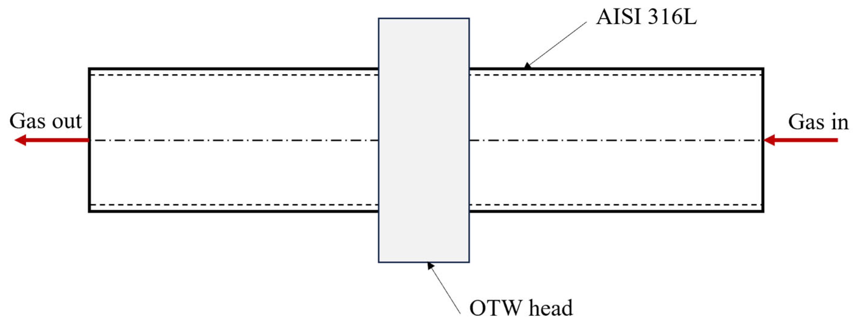
Figure 2. Principle of the experiment.
Thermo 05 00049 g002
Table 2. Experimental parameters and results.
CodeWelding ParametersQ (kJ/mm)Results
Bead GeometryUTS (MPa)Heat Tint Level
I
(A)
AL (mm)Vs
(mm/s)
Gb (LPM)At (ms)W
(mm)
P
(mm)
38-1801.5562000.083.11.13792
38-2801.5683000.073.00.82391
38-3801.57104000.062.90.92283
38-4802.0584000.092.91.02792
38-5802.06102000.071.90.44511
38-6802.0763000.062.80.62783
38-7802.55103000.092.70.82573
38-8802.5664000.082.60.81163
38-9802.5782000.072.30.61073
38-10901.5584000.102.81.23944
38-11901.56102000.083.50.73432
38-12901.5763000.072.30.72711
38-13902.05103000.103.11.02432
38-14902.0664000.092.80.94012
38-15902.0782000.072.00.61971
38-16902.5562000.113.51.75424
38-17902.5683000.092.50.61952
38-18902.57104000.082.40.61281
38-191001.55103000.113.51.23904
38-201001.5664000.102.91.76262
38-211001.5782000.083.61.56522
38-221002.0562000.123.21.76264
38-231002.0683000.104.11.76064
38-241002.07104000.092.50.82203
38-251002.5584000.133.21.13492
38-261002.56102000.113.10.81321
38-271002.5763000.092.90.82282
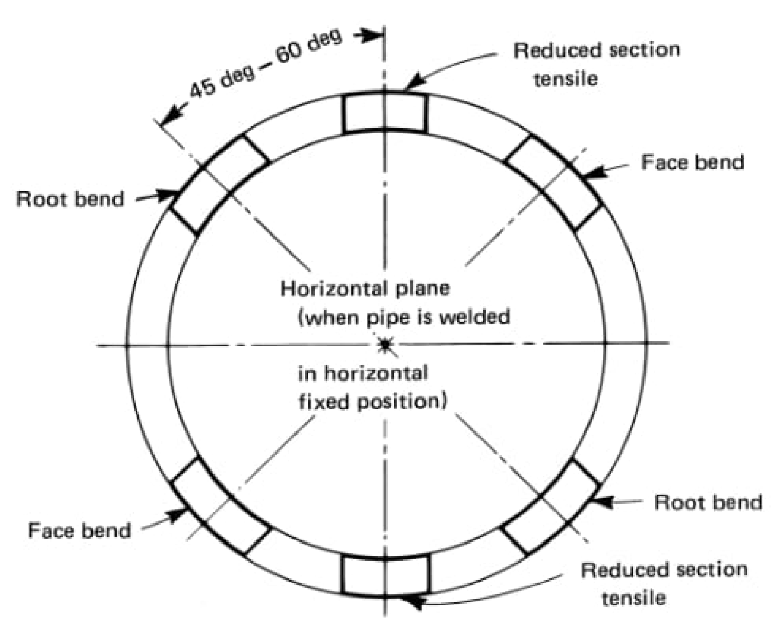
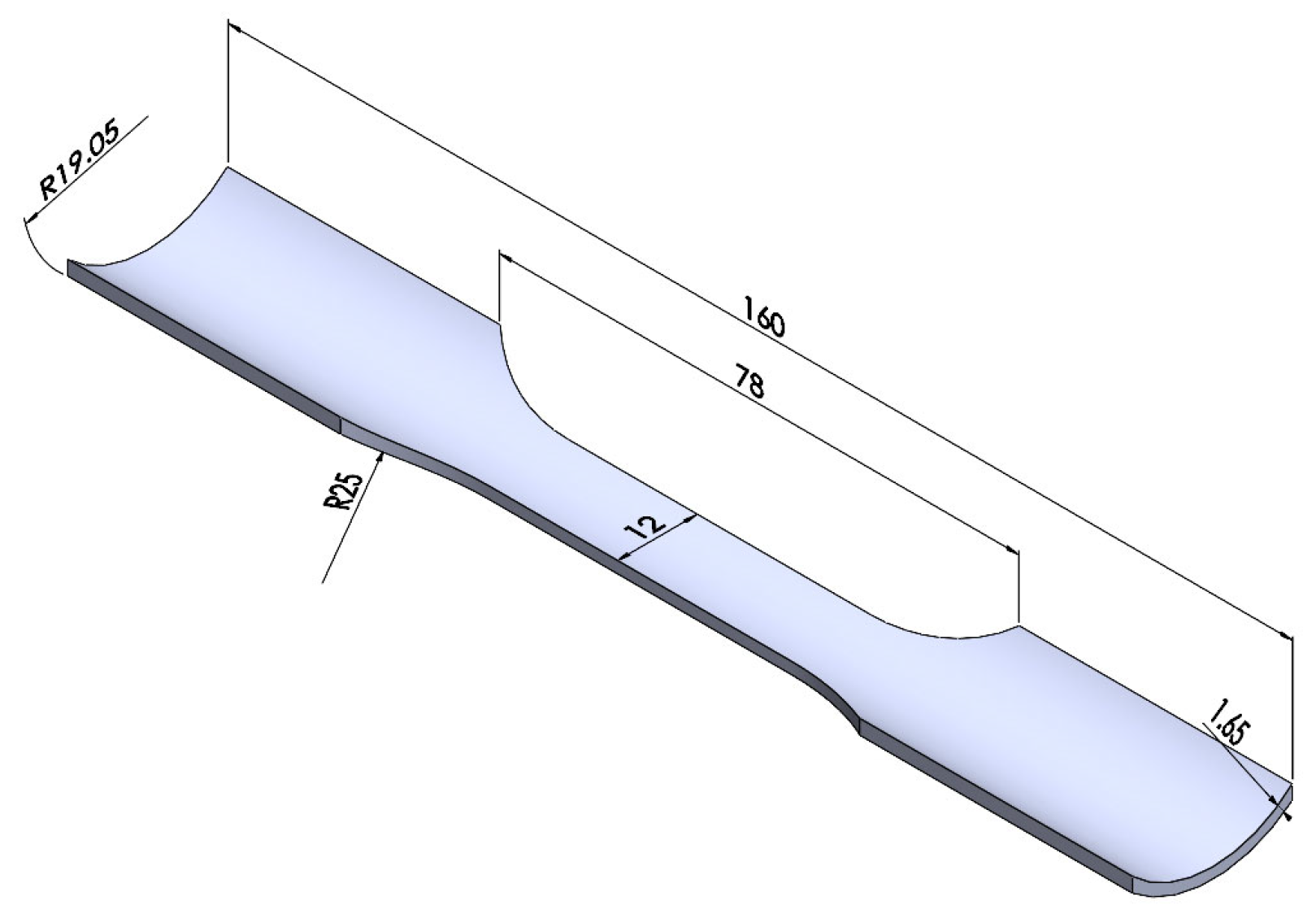
After welding, tensile testing samples had been taken following the ASME IX standard [29] (Figure 3) and the ISO-4136 standard [30] (Figure 4). A specimen preparation procedure consisting of six steps (Figure 5) was carried out prior to observation using the Oxion OX.2153-PLM metallurgical microscope, manufactured by Euromex Microscopen BV, Duiven, The Netherlands.

3. Results and Discussion

3.1. Bead Geometry and Ultimate Tensile Strength

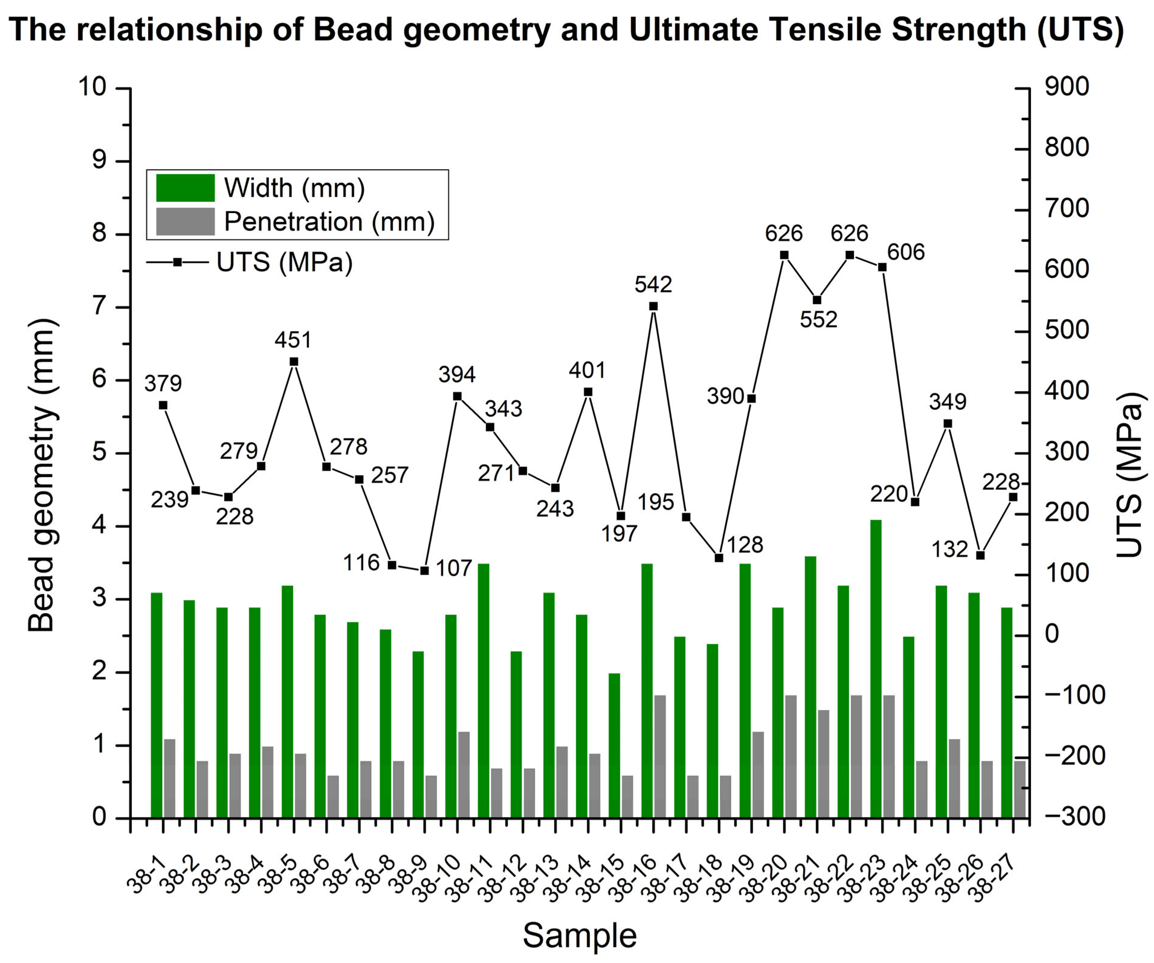
The Visual Examination Acceptance Criteria of AWS D18.1 about Specification for Welding of Austenitic Stainless-Steel Tube and Pipe Systems in Sanitary (Hygienic) Applications requires the minimum face width of the bead to be 2T (T is the thickness of the tube). With T = 1.65 mm in this experiment, the minimum face width of the bead is 3.3 mm. Based on the results in Table 2 and Figure 6, the weld codes 38-11, 38-16, 38-19, 38-21, and 38-23 achieved bead widths ranging from 3.5 mm to 4.1 mm, but the welds achieved full penetration (P ≥ T): welds 38-16, 38-20, 38-22, and 38-23 with a depth of penetration of 1.7 mm. When comparing both criteria, only welds 38-16 and 38-23 passed the requirements, with the same heat input values of 0.11 kJ/mm. But sample 38-23 exhibited a greater bead width, which led to a higher ultimate tensile strength (UTS) of 606 MPa compared to 542 Mpa of sample 38-16. This difference is attributed to the impact of the two parameters, backing gas and arc time, during welding. Considering UTS values, welds 38-20 and 38-22, although not passing the bead width criteria, have a UTS of 2 samples slightly higher than weld 38-23. The results show that heat input values ranging from 0.10 kJ/mm to 0.12 kJ/mm produce welds with full penetration, leading to higher tensile strength. Compared with the study by Agus Widyianto et al. [31], the results of this study show the same trend. In addition, variations in backing gas and arc time also affect the weld formation process, which explains why some welds with high heat input exhibited reduced penetration (weld 38-19). This occurs because backing gas contributes to slowing down the heat transfer of AISI 316L, which is an austenitic stainless steel with the lowest thermal conductivity compared to carbon steel and other alloy steels, and arc time generates a pulse current, which is one method to reduce the heat input received by the basic material [32].

3.2. Heat Tint Level

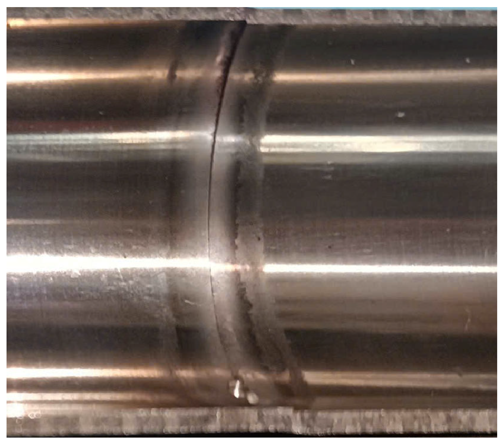
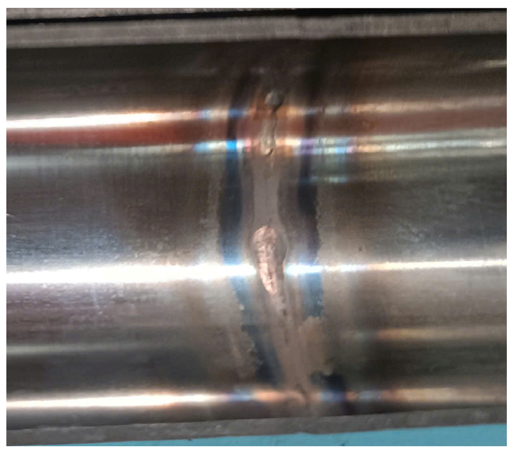
Following the guide to weld discoloration levels on the inside of the austenitic stainless-steel tube of the AWS D18.2 standard (Figure 7), the heat tint level of 27 welds is shown in Table 2. The welds created with heat input levels below 0.10 kJ/mm all remained within the allowable level (Figure 8), whereas welds with higher heat input values tended to exceed the permissible threshold. Specifically, welds 38-10, 38-16, 38-19, and 38-23 reached a heat tint level of 4 when the heat input ranged from 0.10 kJ/mm to 0.12 kJ/mm. Among them, welds 38-16 and 38-23, despite having good bead geometry, exceeded the allowable heat tint level, which is strictly regulated for the inner surface of sanitary tubes at the weld joint (Figure 9). At higher heat input levels, dark heat tint forms along the weld (HAZ—heat-affected zone) during the welding of austenitic stainless steel. This layer of chromium oxide mixed with iron, nickel, and other oxide impurities diffuses onto the surface of the base metal in the HAZ, which reduces the corrosion resistance of austenitic stainless steel [19]. Therefore, controlling HI is crucial in sanitary tube welding because of its negative effect on local corrosion resistance [33].

3.3. Microstructural Analysis

Figure 10 shows the bead geometry at the lowest UTS, the highest UTS, and the highest heat input. As illustrated in Figure 10, distinct differences in weld bead geometry are evident among the three specimens produced with different heat input levels. The weld profile of specimen 38-9 (Figure 10a) exhibited the lowest UTS, primarily due to its limited penetration depth of only 0.6 mm. This low tensile strength is attributed to the relatively small heat input of 0.07 kJ/mm applied during welding. Moreover, welding under such low heat input conditions often leads to instability of the arc, which in this case caused a weld misalignment defect of 0.7 mm. Remarkably, specimen 38-22 achieved full penetration, thereby demonstrating the highest tensile strength. This observation aligns with the findings reported by Ghumman et al. [12]. Conversely, weld 38-25, despite being produced with the highest heat input value of 0.13 kJ/mm, failed to achieve complete penetration, reaching only 1.1 mm with a bead width of 3.2 mm. A comparison of welding parameters revealed that specimen 38-25 was welded with higher arc time and backing gas flow than specimen 38-22, which adversely influenced the cooling behavior of the weld pool. Consequently, both penetration depth and UTS of 38-25 were inferior to those of 38-22.
Figure 11 presents the microstructure of the lowest UTS, the highest UTS, and the highest heat input, highlighting the effect of heat input on microstructural evolution. Specimen 38-25 exhibited the widest HAZ (Figure 11c), resulting in a coarser microstructure in the weld metal (WM) compared to the other two samples. In addition, the rapid cooling during welding, caused by the large arc time (At) and a moderate backing-gas flow rate (Gb), reduced the weld penetration. Consequently, specimen 38-25 showed a low UTS value (349 Mpa) despite having the highest heat input. Moreover, Casalino et al. [34] similarly reported that rapid cooling during welding could lead to chromium carbide precipitation within the HAZ, potentially compromising the corrosion resistance and long-term performance of stainless steels. Conversely, at a low heat input level (0.07 kJ/mm), the specimen exhibited the narrowest HAZ (Figure 11a) and the finest weld metal microstructure (Figure 11d). However, the particle penetration resulted in specimen 38-9 having the lowest UTS value (only 107 Mpa). Analysis of the WM microstructure (Figure 11) revealed that specimen 38-9, which was welded with the lowest heat input, had the finest cellular dendritic structures. Continuously, specimen 38-22 displayed coarser dendrites due to a higher heat input level and reached complete penetration. Interestingly, specimen 38-25, despite having the highest heat input, showed dendritic structures coarser than those of 38-22. Although the heat input levels were similar, variations in arc time (At) and backing-gas flow rate (Gb) significantly affected the weld penetration. As a result, specimen 38-22 achieved the highest UTS value of 626 Mpa.
Overall, these findings confirm that the balance between heat input, cooling rate, and auxiliary parameters such as At and Gb plays a decisive role in determining the microstructural characteristics of welds. The refinement or coarsening of dendritic structures directly influences the UTS and corrosion resistance, with optimized heat input producing welds of superior penetration and mechanical performance.

3.4. Taguchi Analysis

To determine the optimal set of parameters for sanitary tube welding, this study carried out two optimization processes using the Taguchi method in Minitab 21.3: one with UTS targeted as “larger is better,” and the other with heat tint targeted as “smaller is better.”
First, to maximize penetration and UTS, the “larger is better” S/N ratio is adopted and evaluated in accordance with Equation (2) [24]:
S N = 10 l o g ( 1 N i = 1 n 1 y i 2 )
where yi is the data recorded for the i performance characteristic and n is the total count of tests.
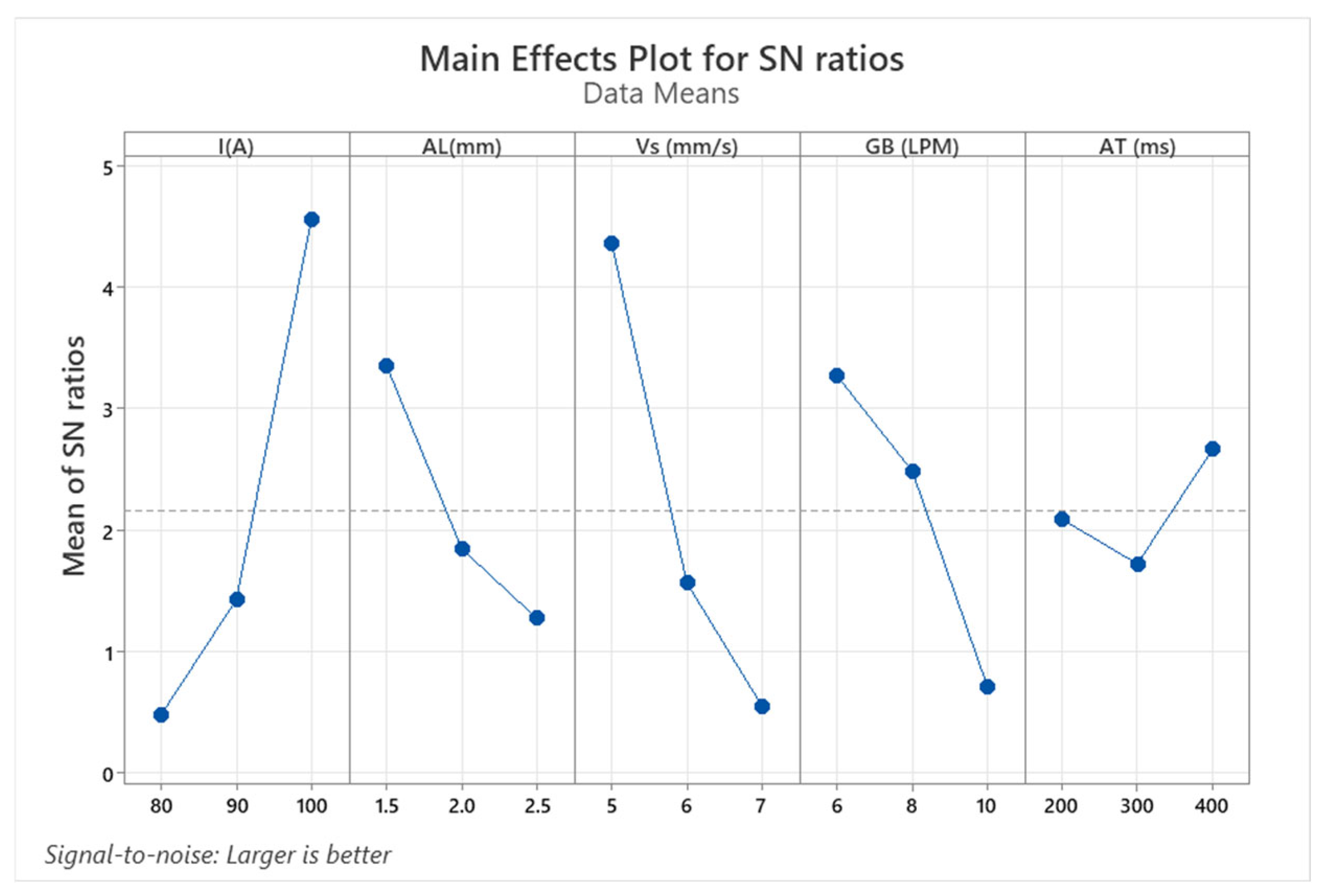
Table 3 shows the response table of the signal-to-noise ratios of the UTS. The results indicate the ranking of the influence of the factors invested in UTS. Among the five examined parameters, two factors that directly contribute to heat input included current (I) and welding speed (Vs), with the highest and second-highest influence, respectively. This finding is consistent with the studies of Adigun et al. [35] and aligns with the results of Pham Son Minh et al. [6], where pulse time was ranked as the third most influential factor. However, in the present study, pulse time was ranked lowest, after backing gas and arc length. This represents a novel finding, as backing gas was shown to significantly influence the cooling process of the weld, thereby reducing penetration and UTS due to the increased flow rate of the backing gas.
Figure 12 presents the main effect plots of the S/N ratios of the UTS. To achieve the highest possible UTS, level 3 is dominant for factor I by an S/N ratio of 4.56 and an S/N ratio of 2.66 for factor arc time (At), whereas level 1 is dominant for arc length (Al), welding speed (Vs), and backing gas (Gb). This means the optimal parameter set to obtain the best UTS is currently at 100 A, arc length at 1.5 mm, welding speed at 5 mm/s, backing gas at 6 LPM, and arc time at 200 ms.
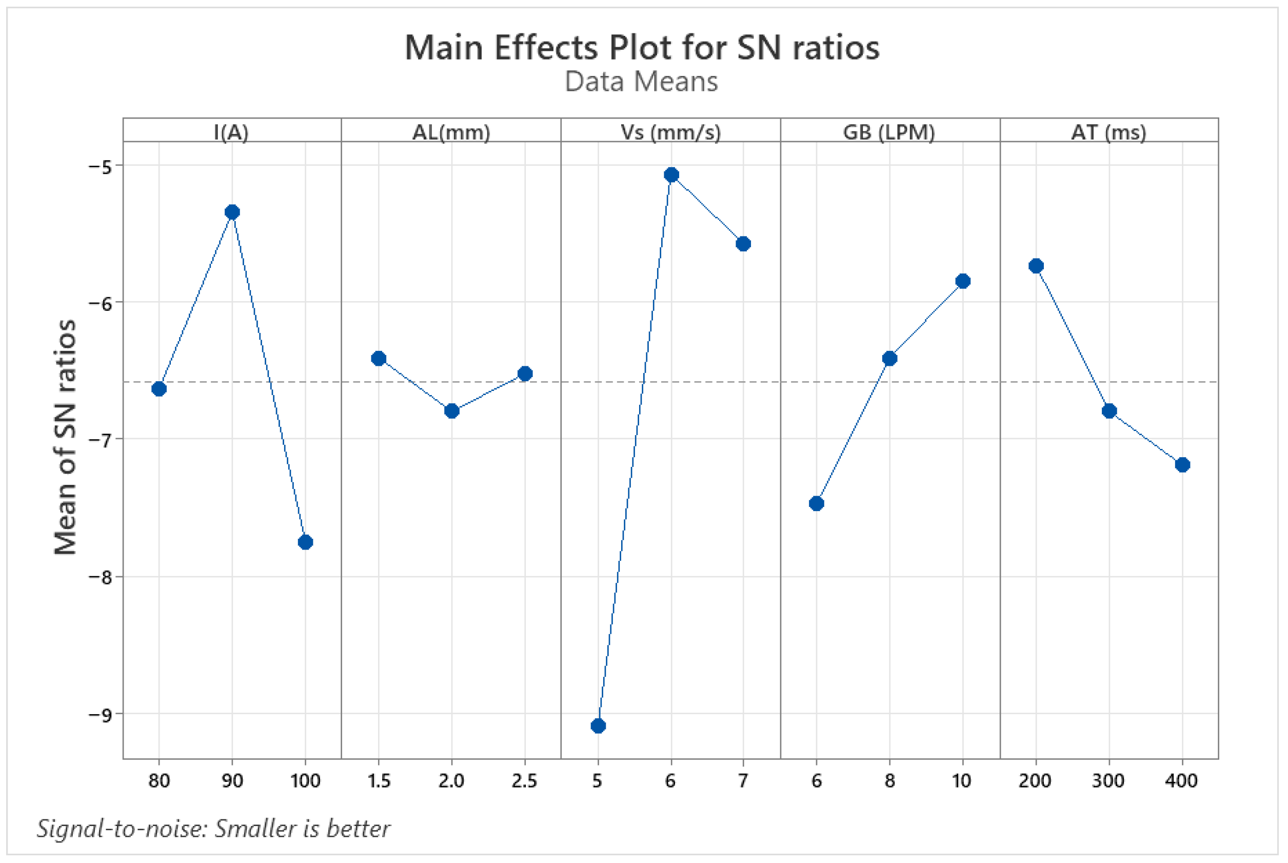
Next, in order to minimize the oxidation on the surface of AISI 316L tubes caused by the influence of heat input, this study evaluated the phenomenon of heat tint through weld surface observation and analysis of post-weld color variation. Heat tint is formed by the precipitation and oxidation of alloying elements (particularly Cr, Fe, and Ni) when the surface temperature exceeds 400 °C during the welding process. So, the “smaller is better” S/N ratio is adopted and evaluated in accordance with Equation (3) [35].
S N = 10 l o g ( 1 N i = 1 n y i 2 )
The Taguchi analysis results to minimize the heat tint level are presented in Table 4. The ranking of the influence of the five factors differs from the results obtained for UTS. The most influential factor for heat tint is welding speed (Vs), followed by current (I), and then backing gas (Gb), with arc time (At) showing the least influence. Once again, it is evident that I and Vs are the two primary parameters governing heat input, and they are also the dominant factors affecting both UTS and heat tint levels. This result demonstrates that heat input plays a decisive role in improving penetration, enhancing UTS [10,32,36], and altering heat tint [18]. As shown in Figure 13, the optimal parameter set for minimizing surface oxidation of AISI 316L was found to be current at 90 A, arc length at 1.5 mm, welding speed at 6 mm/s, backing gas at 10 LPM, and arc time at 200 ms. These findings suggest that the proposed welding parameters provide a practical balance between achieving full penetration, maximizing UTS, and effectively controlling heat tint in orbital TIG welding of sanitary tubes.
By comparing the two sets of parameters proposed in the optimization procedures, it was found that the parameter set targeting maximum UTS corresponds to a heat input of 0.11 kJ/mm, which is higher than the heat input of 0.09 kJ/mm obtained from the heat tint minimization process. According to the experimental data presented in Table 2, heat input values ranging from 0.10 kJ/mm to 0.12 kJ/mm consistently produced welds with full penetration. Therefore, the recommended parameter set includes I = 100 A, Al = 1.5 mm, Vs = 5 mm/s to achieve complete penetration, and Gb = 10 LPM together with At = 200 ms to mitigate weld discoloration. The predictive analysis using the Taguchi-based optimization model estimated the ultimate tensile strength (UTS) of the welded joint to be 548 MPa at the optimal parameter combination of welding current (I) = 100 A, arc length (Al) = 1.5 mm, and welding speed (Vs) = 5 mm/s. In Table 5, the model yielded a desirability index of 0.8497, indicating a high level of agreement with the optimization objectives. The standard error of fit (SE = 55.7 MPa) and the 95% confidence interval (432.7–663.3 MPa) suggest that the predicted mean UTS is statistically reliable, while the 95% prediction interval (267.8–828.3 MPa) reflects the possible variation in individual experimental outcomes due to process fluctuations.
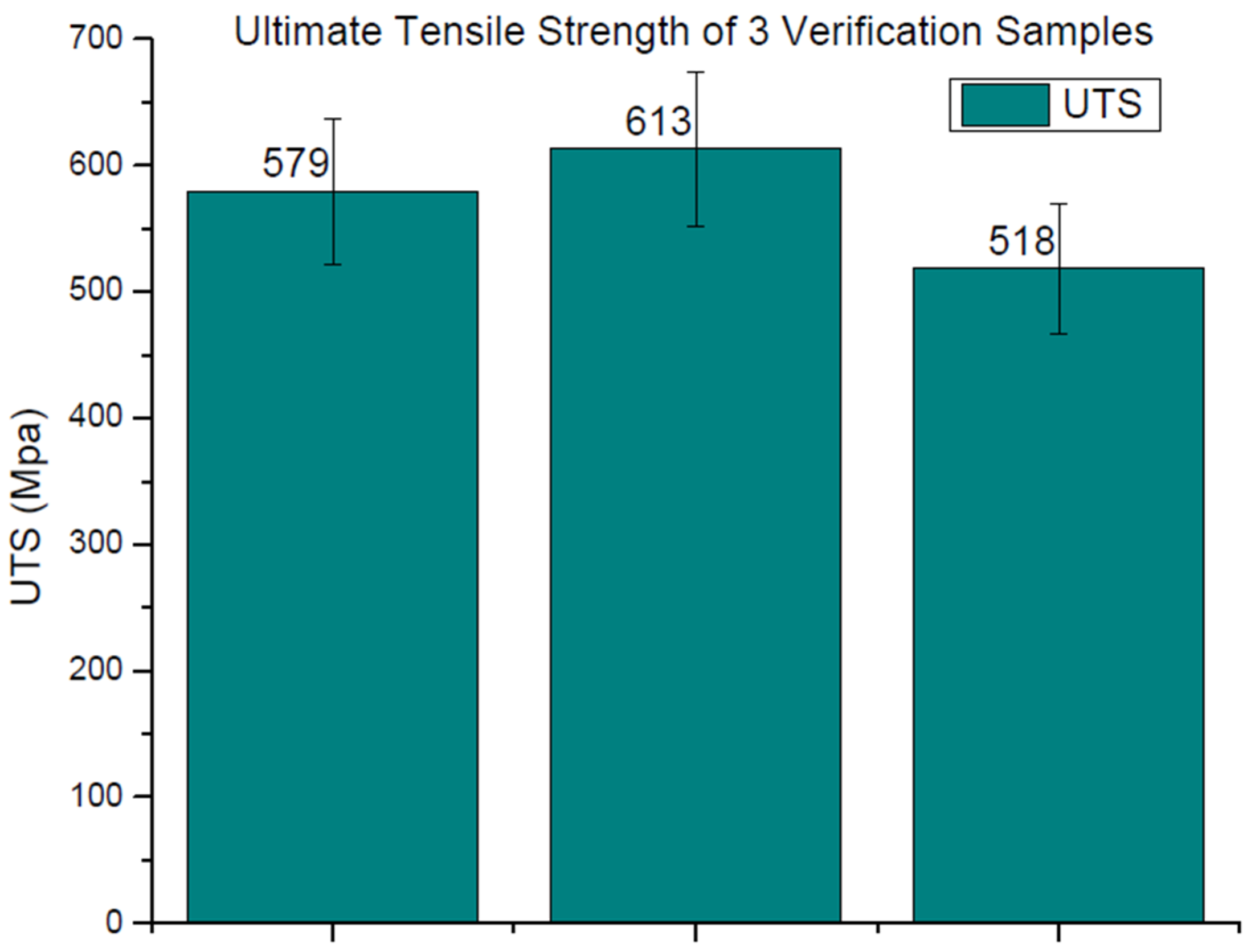
Although the mean prediction demonstrates excellent tensile performance under the selected parameters, the relatively wide prediction interval implies that the welding process may still be sensitive to minor variations in operating conditions or material uniformity. This emphasizes the necessity of conducting confirmation experiments to validate the predicted response and ensure process robustness. Therefore, three welds were performed to validate this parameter set. The UTS results are presented in Figure 14, with measured values of 579 MPa, 613 MPa, and 518 MPa, respectively. All measured values fall within the 95% confidence interval (432.7–663.3 MPa) of the predicted mean, validating the statistical soundness of the model. Furthermore, the experimental data also lie well inside the 95% prediction interval (267.8–828.3 MPa), indicating that the observed variations are consistent with the model’s expected uncertainty range. The relatively small standard deviation among the three welds (σ ≈ 48 MPa) suggests that the process exhibits acceptable reproducibility and moderate sensitivity to external fluctuations such as heat input instability or minor surface condition variations.
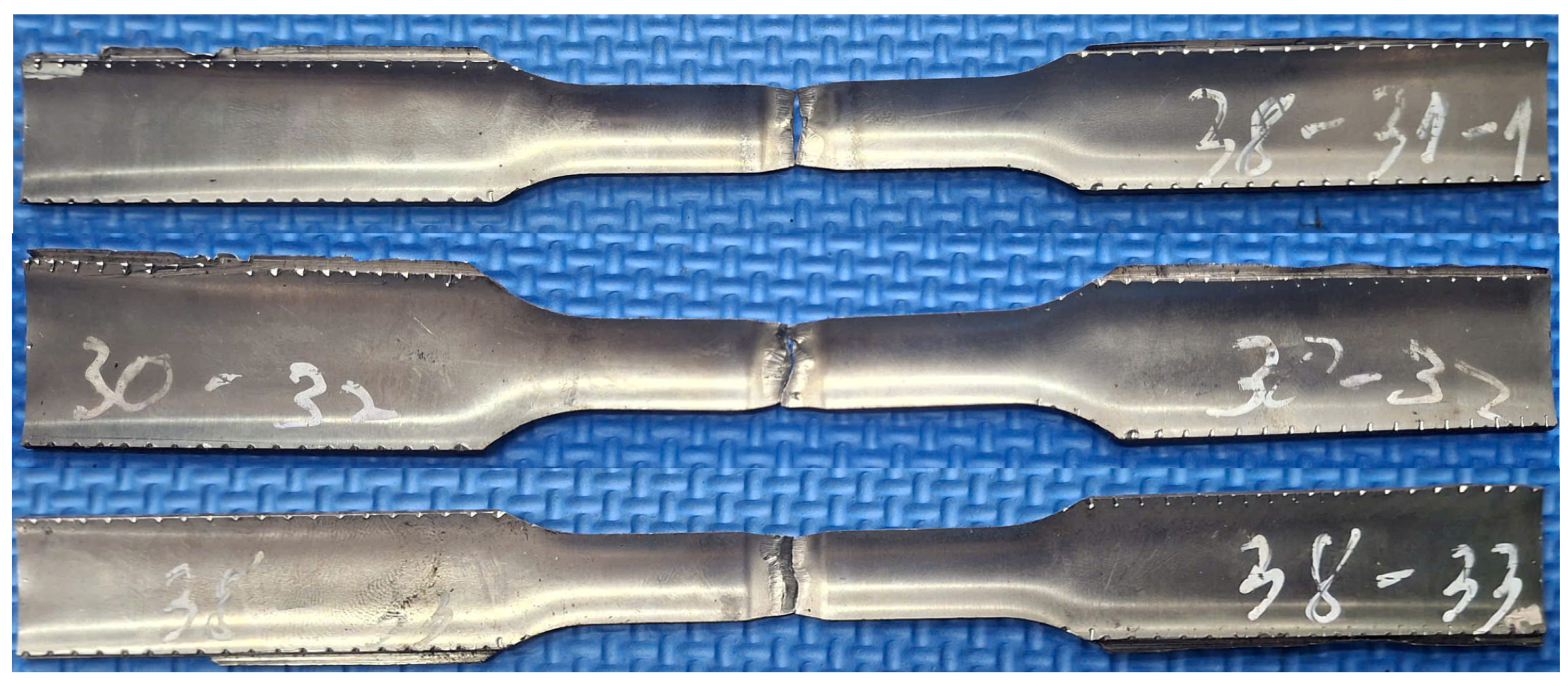
The fracture occurred in the weld region (Figure 15), showing that the joint was weaker than the base material. In addition, the weld discoloration level was measured as Level 2 in Figure 16, which satisfies the AWS D18.2 requirements (Figure 7). These findings demonstrate that the proposed parameter set successfully fulfills the objectives of this study. These results are consistent with previous findings on the critical role of heat input in determining both penetration and surface quality of stainless steel welds [12,34], yet this study provides a novel contribution by demonstrating that the combined optimization of UTS and weld discoloration can be simultaneously achieved through careful adjustment of backing gas flow and arc time in OTW of sanitary AISI 316L tubes. In addition, examination of the fracture locations of the three tensile test specimens revealed that the failure occurred within the weld zone or its vicinity, as the UTS of the welds was lower than that of the base metal.

4. Conclusions

This study investigates the influence of heat input and associated process parameters on the weld quality of sanitary AISI 316L stainless steel tubes welded using the Orbital TIG Welding (OTW) technique. A total of 27 welds were performed and optimized using the Taguchi method to simultaneously maximize ultimate tensile strength (UTS) and minimize heat tint level in accordance with AWS D18.2 standards. The results demonstrate some critical points:
-
Heat input is the dominant factor affecting both penetration and heat tint levels. For full penetration and improved tensile properties, the most influential factors were current (I) and welding speed (Vs). Moreover, backing gas (Gb) and arc time (At) played significant roles in reducing weld discoloration.
-
Two optimization strategies were established: one prioritizing UTS with heat input (Q) ≈ 0.11 kJ/mm, and another minimizing heat tint with heat input (Q) ≈ 0.09 kJ/mm. By combining both approaches, the optimal parameter set was identified as I = 100 A, Al = 1.5 mm, Vs = 5 mm/s, Gb = 10 LPM, and At = 200 ms. Experimental validation confirmed the effectiveness of this parameter set, yielding an average UTS of 570 MPa and a heat tint level of 2, satisfying AWS D18.2 requirements.
-
Overall, this study highlights that the balance between adequate penetration and acceptable weld discoloration can be achieved by carefully controlling heat input and optimizing process parameters. The findings provide practical guidelines for the sanitary tubing industry, contributing to improved mechanical performance and corrosion resistance of OTW joints in AISI 316L stainless steel. In addition, the validation results demonstrate that the optimized parameter set not only maximizes the UTS but also maintains robust performance under repeated trials. This consistency supports the applicability of the Taguchi approach in determining parameter combinations that yield high-quality welds with minimal variability. Future work may incorporate additional replications or hybrid modeling (e.g., Taguchi–Response Surface Methodology or Artificial Neural Networks -based refinement) to improve prediction accuracy, better correlate with microstructural characteristics, and further enhance the tensile strength of the welds.

Author Contributions

N.-T.T.: Conceptualization, funding acquisition; N.-T.T. and V.-T.N.: writing—original draft, investigation; N.-T.T. and V.-S.N.: analysing, visualization; N.-T.T., T.T.D. and V.-T.N.: writing, review and editing. All authors have read and agreed to the published version of the manuscript.

Funding

The research topic was supported by the Youth Incubator for Science and Technology Programme, managed by Youth Promotion Science and Technology Center—Ho Chi Minh Communist Youth Union and Department of Science and Technology of Ho Chi Minh City; the contract number is “26/2024/HĐ-KHCNT-VU” signed on 30 December 2024.

Data Availability Statement

The data used to support the findings of this study are available from the corresponding author upon request.

Acknowledgments

This study is supported by the student group consisting of Le Van Dung, Tran Quoc Hoang, and Do Thi Phuong Thao.

Conflicts of Interest

The authors declare no conflicts of interest.

References

  1. Mannion, B. Orbital Welding: A Comprehensive Guide; Emerald Publishing: Leeds, UK, 2004. [Google Scholar]
  2. Joshi, O.P.; Arunkumar, P. Overview of orbital welding technology. Int. J. Innov. Sci. Eng. Technol. 2015, 2, 958–959. [Google Scholar]
  3. Polysoude Nantes France SAS. The Orbital Welding Handbook; Polysoude Nantes France SAS: Nantes, France, 2016; Available online: https://www.polysoude.com/wp-content/uploads/2017/01/DOC_Orbital-welding-Handbook_EN.pdf (accessed on 30 October 2025).
  4. Singh, N.K.; Pradhan, S.K. Experimental and numerical investigations of pipe orbital welding process. Mater. Today Proc. 2020, 27, 2964–2969. [Google Scholar] [CrossRef]
  5. Baskoro, A.S.; Widyianto, A.; Prasetyo, E.; Kiswanto, G. The Taguchi and Response Surface Method for optimizing orbital pipe welding parameters in pulsed Current Gas tungsten arc welding (PC-GTAW) for SS316L. Trans. Indian Inst. Met. 2024, 77, 1607–1620. [Google Scholar] [CrossRef]
  6. Minh, P.S.; Nguyen, V.T.; Do, T.T.; Uyen, T.M.T.; Toan, H.D.S.; Linh, H.T.T.; Nguyen, V.T.T. Parameter optimization in orbital TIG welding of SUS 304 stainless steel pipe. Metals 2023, 14, 5. [Google Scholar] [CrossRef]
  7. Mengistie, A.K.; Bogale, T.M. Development of automatic orbital pipe MIG welding system and process parameters’ optimization of AISI 1020 mild steel pipe using hybrid artificial neural network and genetic algorithm. Int. J. Adv. Manuf. Technol. 2023, 128, 2013–2028. [Google Scholar] [CrossRef]
  8. Huitt, W.M. Bioprocessing Piping and Equipment Design: A Companion Guide for the ASME BPE Standard; John Wiley & Sons: Hoboken, NJ, USA, 2016. [Google Scholar]
  9. Unnikrishnan, R.; Idury, K.S.; Ismail, T.; Bhadauria, A.; Shekhawat, S.; Khatirkar, R.K.; Sapate, S.G. Effect of heat input on the microstructure, residual stresses and corrosion resistance of 304L austenitic stainless steel weldments. Mater. Charact. 2014, 93, 10–23. [Google Scholar] [CrossRef]
  10. Patro, R.; Pradhan, S.K. Finite element simulation and optimization of orbital welding process parameters. Mater. Today Proc. 2018, 5, 12886–12900. [Google Scholar] [CrossRef]
  11. Rajakumar, J. Numerical investigation of heat transfer behaviour during TIG welding of stainless steel pipes for various welding heat input conditions. Am. J. Mech. Ind. Eng. 2017, 2, 117. [Google Scholar] [CrossRef]
  12. Ghumman, K.Z.; Ali, S.; Khan, N.B.; Khan, M.I.; Ali, H.T.; Ashurov, M. Optimization of TIG welding parameters for enhanced mechanical properties in AISI 316L stainless steel welds. Int. J. Adv. Manuf. Technol. 2024, 136, 353–365. [Google Scholar] [CrossRef]
  13. Rodriguez-Vargas, B.R.; Stornelli, G.; Hernandez-Flores, J.E.; Imbimbo, E.; Di Schino, A. Influence of heat input on austenite/ferrite ratio in the weld zone of robotic GTAW duplex stainless steel 2205 weld bead. Acta Metall. Slovaca 2025, 31, 124–128. [Google Scholar] [CrossRef]
  14. Hussein, N.I.S.; Ayof, M.N.; Nordin, S. Tensile Strength of Orbital Welded Mild Steel Tubes with Dissimilar Thickness. Int. J. Mater. Mech. Manuf. 2015, 4, 56–59. [Google Scholar] [CrossRef]
  15. Ai, Y.; Dong, G.; Yuan, P.; Liu, X.; Yan, Y. The influence of keyhole dynamic behaviors on the asymmetry characteristics of weld during dissimilar materials laser keyhole welding by experimental and numerical simulation methods. Int. J. Therm. Sci. 2023, 190, 108289. [Google Scholar] [CrossRef]
  16. Engineering Department, Arc Machines, Inc. Maximizing the Weldability of Stainless Steel with Orbital Welding. Arc Machines. 30 September 2021. Available online: https://resources.arcmachines.com/maximizing-the-weldability-of-stainless-steel-with-orbital-welding (accessed on 30 October 2025).
  17. Kolařík, L.; Kolaříková, M.; Husák, O. Orbital welding of heterogeneous joints. Mater. Sci. Forum 2018, 919, 10–17. [Google Scholar] [CrossRef]
  18. Łabanowski, J.; Głowacka, M. Heat tint colours on stainless steel and welded joints. Weld. Int. 2011, 25, 509–512. [Google Scholar] [CrossRef]
  19. Tuthill, A.H.; Avery, R.E.; Nickel Development Institute. Heat Tints on Stainless Steels Can Cause Corrosion Problems. 1999. Available online: https://nickelinstitute.org/media/1696/heattintsonstainlesssteelscancausecorrosionproblems_14050_.pdf (accessed on 30 October 2025).
  20. Kimbrel, K. Determining Acceptable Levels of Weld Discoloration on Mechanically Polished and Electropolished Stainless Steel Surfaces. 2011. Available online: https://ultracleanep.com/wp-content/uploads/2014/06/Weld-color-Pharmaceutical-Engineeringl.pdf?utm_source=chatgpt.com (accessed on 30 October 2025).
  21. Tseng, K.H.; Hsu, C.Y. Performance of activated TIG process in austenitic stainless steel welds. J. Mater. Process. Technol. 2010, 211, 503–512. [Google Scholar] [CrossRef]
  22. Singh, P.K.; Kumar, S.D.; Patel, D.; Prasad, S.B. Optimization of vibratory welding process parameters using response surface methodology. J. Mech. Sci. Technol. 2017, 31, 2487–2495. [Google Scholar] [CrossRef]
  23. Rocha, V.R.; Lobato, F.S.; de Assis, P.A.Q.; Ribeiro, C.R.; da Cunha, S.S.; Vilarinho, L.O.; Andrade, J.R.; da Silva, L.R.R.; dos Santos Paes, L.E. Parametric optimization of artificial neural networks and machine learning techniques applied to small welding datasets. Processes 2025, 13, 2711. [Google Scholar] [CrossRef]
  24. Lakache, H.E.; May, A.; Badji, R. Optimization of the RFW Process Parameters by Using the Taguchi Method for the Ti6Al4V grade-5 alloy. Acta Metall. Slovaca 2023, 29, 155–160. [Google Scholar] [CrossRef]
  25. Nobrega, G.; Souza, M.S.; Rodríguez-Martín, M.; Rodríguez-Gonzálvez, P.; Ribeiro, J. Parametric optimization of the GMAW welding process in thin thickness of austenitic stainless steel by Taguchi Method. Appl. Sci. 2021, 11, 8742. [Google Scholar] [CrossRef]
  26. Prasetyo, E.; Baskoro, A.S.; Widyianto, A.; Kiswanto, G. Identifying the influence of orbital pipe welding parameters on mechanical properties using SS316L pipe. East. Eur. J. Enterp. Technol. 2023, 5, 72–84. [Google Scholar] [CrossRef]
  27. Akbari, D.; Sattari-Far, I. Effect of the welding heat input on residual stresses in butt-welds of dissimilar pipe joints. Int. J. Press. Vessel. Pip. 2009, 86, 769–776. [Google Scholar] [CrossRef]
  28. Kik, T.; Garašić, I.; Perić, M.; Landek, D.; Jurica, M.; Tonković, Z. Modifications of the heat source model in numerical analyses of the metal-cored arc welding process. Energy 2024, 302, 131811. [Google Scholar] [CrossRef]
  29. ASME Boiler and Pressure Vessel Code, Section IX; Welding, Brazing, and Fusing Qualifications; The American Society of Mechanical Engineers: New York, NY, USA, 2021.
  30. ISO 4136; Destructive Tests on Welds in Metallic Materials—Transverse Tensile Test. International Organization for Standardization: Geneva, Switzerland, 2021.
  31. Widyianto, A.; Baskoro, A.S.; Kiswanto, G.; Ganeswara, M.F.G. Effect of welding sequence and welding current on distortion, mechanical properties and metallurgical observations of orbital pipe welding on SS 316L. East. Eur. J. Enterp. Technol. 2021, 2, 22–31. [Google Scholar] [CrossRef]
  32. Pal, K.; Pal, S.K. Effect of pulse parameters on weld quality in pulsed gas metal arc welding: A review. J. Mater. Eng. Perform. 2010, 20, 918–931. [Google Scholar] [CrossRef]
  33. Zatkalíková, V.; Uhríčik, M.; Markovičová, L.; Pastierovičová, L.; Kuchariková, L. The effect of sensitization on the susceptibility of AISI 316L biomaterial to pitting corrosion. Materials 2023, 16, 5714. [Google Scholar] [CrossRef]
  34. Casalino, G.; Angelastro, A.; Perulli, P.; Casavola, C.; Moramarco, V. Study on the fiber laser/TIG weldability of AISI 304 and AISI 410 dissimilar weld. J. Manuf. Process. 2018, 35, 216–225. [Google Scholar] [CrossRef]
  35. Adigun, O.; Adebayo, A.; Abiola, O. The effect of welding parameter on the tensile and impact properties of weldments. Am. J. Mech. Mater. Eng. 2025, 9, 37–42. [Google Scholar] [CrossRef]
  36. Baskoro, A.S.; Kiswanto, G.; Widyianto, A. Optimization of PC-GTAW orbital welding parameters of AISI 304L stainless steel pipe using ANOVA and Taguchi method. IOP Conf. Ser. Mater. Sci. Eng. 2020, 727, 012007. [Google Scholar] [CrossRef]
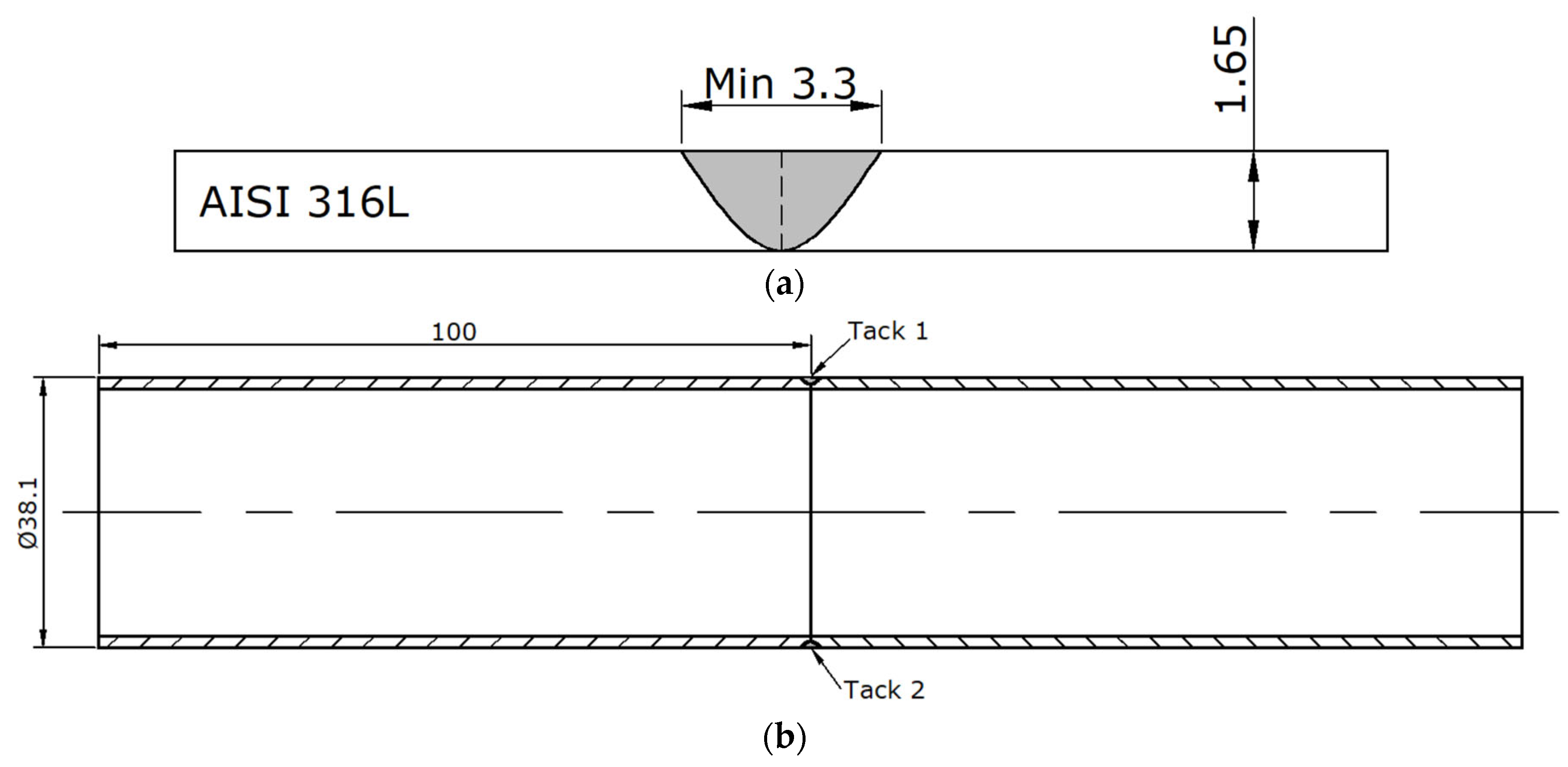
Figure 1. AISI 316L specimen for the experiment. (a) Weld geometry; (b) Dimensions and tack positions.
Thermo 05 00049 g001
Figure 3. Sampling of tensile test for tube.
Thermo 05 00049 g003
Figure 4. Profile of tensile testing sample.
Thermo 05 00049 g004
Figure 5. Proccess of metallurgical preparation.
Thermo 05 00049 g005
Figure 6. The relationship between bead geometry and UTS value.
Thermo 05 00049 g006
Figure 7. Weld discoloration levels on inside of AISI 316 tube according to AWS D18.2 standard.
Thermo 05 00049 g007
Figure 8. Heat tint level of weld 38-20. (accept based on AWS D18.2).
Thermo 05 00049 g008
Figure 9. Heat tint level of weld 38-23. (reject based on AWS D18.2).
Thermo 05 00049 g009
Figure 10. Bead geometry with scale 50X. (a) 38-9; (b) 38-22; (c) 38-25.
Thermo 05 00049 g010
Figure 11. Microstructure of 38-9, 38-22, 38-25. (a) 38-9_X100; (b) 38-22_X100; (c) 38-25_X100; (d) 38-9_X200; (e) 38-22_X200; (f) 38-25_X200.
Thermo 05 00049 g011aThermo 05 00049 g011b
Figure 12. Main effect plots of S/N ratios of the maximum UTS.
Thermo 05 00049 g012
Figure 13. Main effect plots of S/N ratios for the minimum Heat tint level.
Thermo 05 00049 g013
Figure 14. The ultimate tensile strength of three validated samples.
Thermo 05 00049 g014
Figure 15. Verification Samples after tensile testing.
Thermo 05 00049 g015
Figure 16. Weld heat tint of three verification samples.
Thermo 05 00049 g016
Table 1. Chemical composition of AISI 316L [8].
Sanitary TubeComposition, Max, %
CMnSiPSMoNiCr
AISI 316L0.0261.480.410.0320.00782.21610.2716.11
Table 3. Responses of the signal-to-noise ratios of the UTS.
LevelI (A)Al (mm)Vs (mm/s)Gb (LPM)At (ms)
S/N ratio10.48423.35214.35503.26892.0879
21.42921.84711.56522.48731.7220
34.55981.27390.55290.71692.6632
Delta4.07562.07823.80212.55200.9412
Rank14235
Table 4. Responses of the signal-to-noise ratios of the heat tint levels.
LevelI (A)Al (mm)Vs (mm/s)Gb (LPM)At (ms)
S/N ratio1−6.639−6.412−9.088−7.472−5.743
2−5.352−6.803−5.074−6.412−6.803
3−7.750−6.526−5.579−5.857−7.195
Delta2.3980.3914.0141.6161.452
Rank25134
Table 5. Variable setting and Multiple response prediction.
VariableSetting
I (A)100
Al (mm)1.5
Vs (mm/s)5
ResponseFitSE Fit95% CI95% PI
UTS (MPa)548.055.7(432.7, 663.3)(267.8, 828.3)
Disclaimer/Publisher’s Note: The statements, opinions and data contained in all publications are solely those of the individual author(s) and contributor(s) and not of MDPI and/or the editor(s). MDPI and/or the editor(s) disclaim responsibility for any injury to people or property resulting from any ideas, methods, instructions or products referred to in the content.