Article

Implementation of Carbon Utilization Technologies and Thermodynamic Organic Rankine Cycles in Biogas Combined Cycle Power Plants

by
Gerardo G. Esquivel-Patiño
1,
Fabricio Nápoles-Rivera
2 and
Arturo Jiménez-Gutiérrez
1,*
1
Department of Chemical Engineering, Instituto Tecnológico de Celaya, Tecnológico Nacional de México, Celaya 38010, Gto., Mexico
2
Chemical Engineering Department, Universidad Michoacana de San Nicolás de Hidalgo, Morelia 58060, Mich., Mexico
*
Author to whom correspondence should be addressed.
Thermo 2025, 5(4), 43; https://doi.org/10.3390/thermo5040043
Submission received: 11 August 2025 / Revised: 1 October 2025 / Accepted: 16 October 2025 / Published: 22 October 2025

Abstract

Biogas has been identified as a sustainable resource of renewable and clean energy because of its social, economic, and environmental benefits. In this work, the analysis of a biogas combined cycle power plant coupled with a carbon capture and utilization (CCU) technology and an organic Rankine cycle (ORC) was considered. The integrated process was subjected to a multi-objective assessment considering energy, economic, environmental, and safety items. The CCU system was taken to produce syngas as a value-added product, and the use of different working fluids for the ORC, namely, R1234yf, R290, and R717, was also examined. Such working fluids were selected to represent options with varying environmental and inherent safety implications. It was shown that the integration of the CCU and ORC components to the biogas cycle plant can provide significant benefits that include a 48.65 kt/year syngas production, a decrease in carbon capture energy penalty by 33%, and a reduction in e-CO2 emissions above 80% with respect to the stand-alone power plant. Comparison with conventional technologies also showed important environmental benefits. The analysis of inherent safety showed that the selection of working fluids for the ORC can have a significant impact on the process risk. From the set of working fluids considered in this work, R717 provided the best choice for the integrated system based on its lowest operational risk and the highest electricity production (355 kWe). The multi-objective approach used in this work allowed the quantification of benefits provided by the integration of CCUs and ORCs with respect to the base process within an overall economic, sustainability, and inherent safety assessment.

1. Introduction

The environmental impact caused by power plants based on fossil fuels has boosted interest in the use of renewable sources of energy such as solar, wind, biomass, and biogas options [1,2]. According to the International Energy Agency (IEA), energy-related carbon emissions increased by 0.8% in 2024, which contributed to a new high level of atmospheric CO2 concentrations estimated at 422.5 ppm [3].
As bioenergy technologies can achieve net zero carbon emissions and even potentially produce negative emission values when they are coupled with carbon capture processes, they have become an important pathway to achieve today’s global environmental goals [4,5,6]. The use of bioenergy technologies has increased on average by about 4% per year between 2010 and 2023 [7]. Efforts in bioenergy development are needed in order to reach the global net zero emissions scenario goal.
Among bioenergy alternatives, biogas has been identified as a sustainable and versatile energy carrier [8,9,10]. Such versatility allows its use as an industrial raw material, as a source of electrical and thermal energy, and as a component of the transportation sector [11,12,13]. Biogas can be produced from bio-resources such as agricultural waste, food waste, and wastewater [14,15,16,17,18]. Wastewater is a carrier of carbon energy, which can be used to produce biogas, and therefore power [19,20]. Landfills are also important as biogas sources because they have become the main choice for municipal solid waste disposal in many countries, representing the third largest global source of anthropogenic methane emissions (~10%) [21,22,23,24]. All the sources mentioned above produce biogas with compositions of around 65%vol methane and 35%vol carbon dioxide as main components [25].
Biogas can be used to produce electricity in power plants, among which a combined cycle power plant structure, based on the integration of gas and steam turbines, is the most widely used technology because of its higher thermal efficiency with respect to the conventional single gas or steam systems, or the combined heat and power technology [26,27]. Carbon emissions from this processing structure, nonetheless, are still a major factor that needs further improvement. Alternatives to mitigate the environmental harm caused by carbon emissions include the implementation of carbon capture and utilization (CCU) technologies, through which CO2 can be used to produce value-added chemicals to improve the process economics, as well as to contribute towards the design of more sustainable systems [28].
The efficiency of such arrangements can be further increased with the implementation of organic Rankine cycles (ORCs), which use working fluids with low boiling points to generate electricity in a turbine, taking advantage of waste energy from process streams [29,30,31,32]. Yağlı et al. [33] analyzed the coupled structure of a combined heat and power engine with a subcritical and a supercritical ORC using R245fa as working fluid and showed that supercritical conditions provide the best power output and thermal efficiency. Baccioli et al. [34] studied the combination of a micro-gas turbine with an ORC and found that it is possible to achieve a thermal energy recovery of 77%. Thermodynamic considerations based on exergy and energy balances have also been reported [35,36,37]. Under such a modeling formulation, it has been found that an energy recovery system with a high exergy efficiency can reduce fuel consumption [38,39].
Even when ORCs and carbon capture process integration can provide energy and environmental benefits, it should be noted that their implementation requires additional chemicals and equipment units that may affect other aspects, such as the process risk. For instance, Yang et al. [40] showed that most of the alternative working fluids that provide low global warming potential (GWP) are flammable. For CCU technologies, incidents may occur due to the release of flammable absorbents such as monoethanolamine (MEA) or diethanolamine (DEA), as well as chemicals or fuels such as methane, methanol, and syngas, whose effects have been analyzed through applications of quantitative risk assessment methodologies [41,42]. These works illustrate the need to assess inherent safety as part of the analysis and design of integrated power plants.
In this work, the assessment of the integration of CCU and an ORC into a combined cycle power plant that uses biogas as an energy resource to produce a more efficient and sustainable power structure is analyzed. From the possible value-added chemicals that the CCU system can produce, syngas is taken as the production scenario. The effect of using different working fluids for the ORC on the performance of the system is also addressed. Economic, energy, environmental, and inherent safety factors are considered as part of the system analysis, which is aided with the use of the Aspen Plus process simulator. The environmental effects of the proposed integrated system with respect to the use of conventional technologies are also considered.

2. Materials and Methods

Taking as a basis a 6.3 MW biogas combined cycle (BGCC) power plant as reported by Kang et al. [27], we consider the integration of CCUs and ORCs, for which we analyze the use of R1234yf, R290, and R717 as working fluids. The working fluids were selected following the suggestions by Kajurek et al. [43], which are related to the wasted heat source temperature (100 to 120 °C for our study) and the use of working fluids that yield low GWP.
The following items from this work should be highlighted. To improve the performance of the system, energy integration between the BGCC power plant and CCU wasted energy streams with the ORC working fluid was also considered. The performance of the integrated structure is compared to that of the stand-alone BGCC power plant. Aspen Plus simulations of the BGCC, CCU, and ORC processes are used to provide the process data for the system analysis. A systems analysis based on a multi-objective formulation that includes energy, economic, environmental, and inherent safety items is carried out to provide a more complete assessment of the integrated structure than that given by the consideration of isolated individual components.

2.1. BGCC, CCU, and ORC Process Simulations

Thermodynamic properties were estimated using the Peng–Robinson equation of state with the Boston–Mathias modification, along with Aspen Physical Property Methods (STEAMNBS) for the natural gas combustion process and the conventional Rankine cycle [44]. The simulation of the biogas power plant was carried out with data from Kang et al. [27]. Figure 1 shows the flowchart of the Aspen simulation that includes each equipment unit for the Brayton and the Rankine cycles.
In the process, compressed air and biogas are fed to a combustion chamber (CBCH), and the combustion gases (EG) are used to generate power in the gas turbine (GT). The hot gases are sent to an evaporator (EVAP) and an economizer (ECON) to transfer heat to a water stream (WS), which is converted into steam that is used to produce power in the steam turbine (ST). Finally, steam is condensed and sent back to the economizer to complete the Rankine cycle. The W-ADP stream is a heating water stream that is fed to the anaerobic digestion plant (ADP), where biogas is produced.
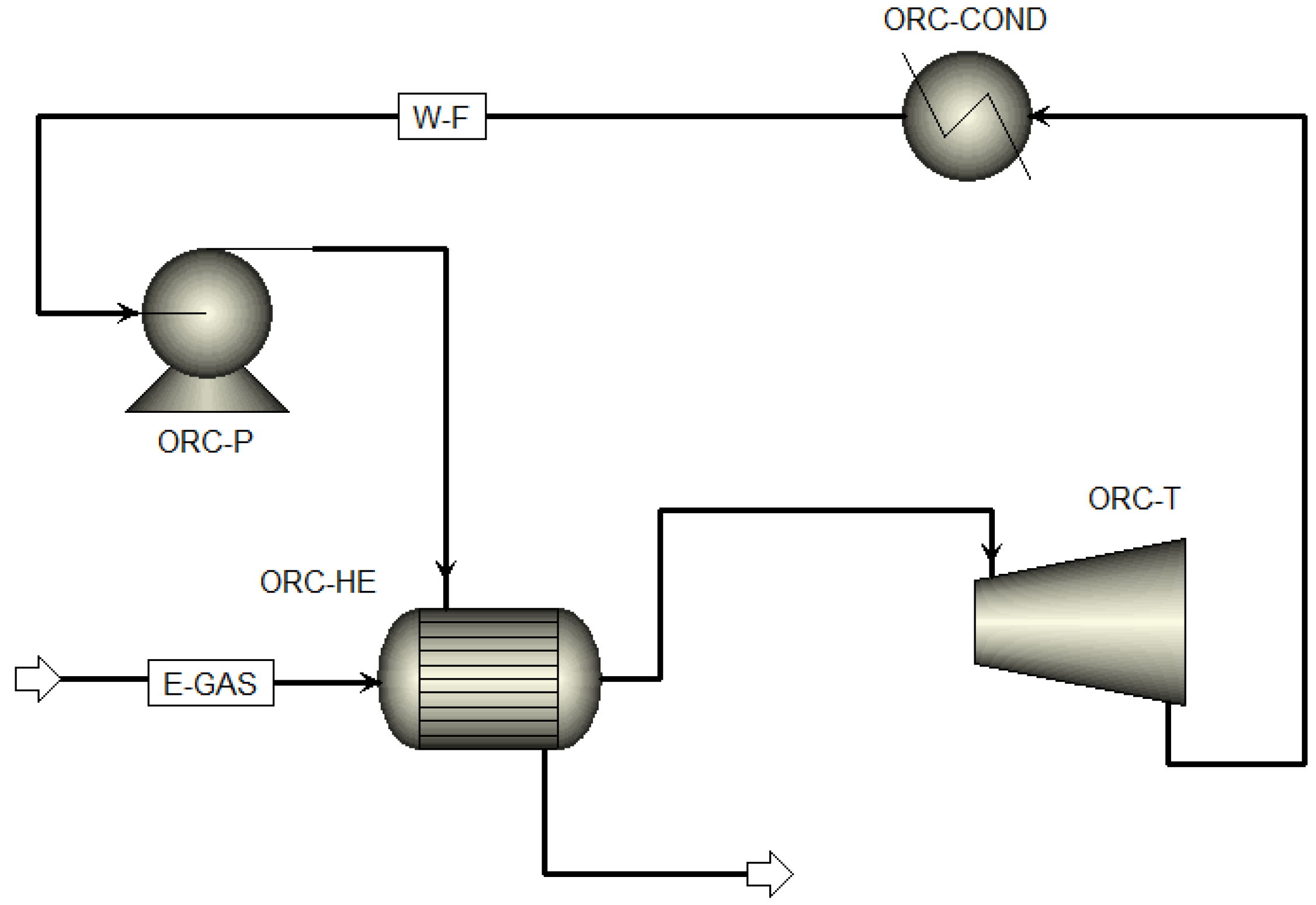
For the ORC, the NIST Reference Fluid Thermodynamic and Transfer Properties (REFPROPs) platform was used. The ORC process consists of a pump, an evaporator, a condenser, and a turbine; the ORC flowsheet is shown in Figure 2. The parameters of each equipment unit and the conditions for each working fluid were also taken from the work by Kajurek et al. [43]. For the ORC simulation, the condensation temperature was fixed at 30 °C with an evaporation temperature of 80 °C, as suggested by Kajurek et al. [43]. The ORC was simulated first for each working fluid to deliver 1 MW of production power. The main parameters for the simulation of the integrated BGCC-ORC system are reported in Table 1.
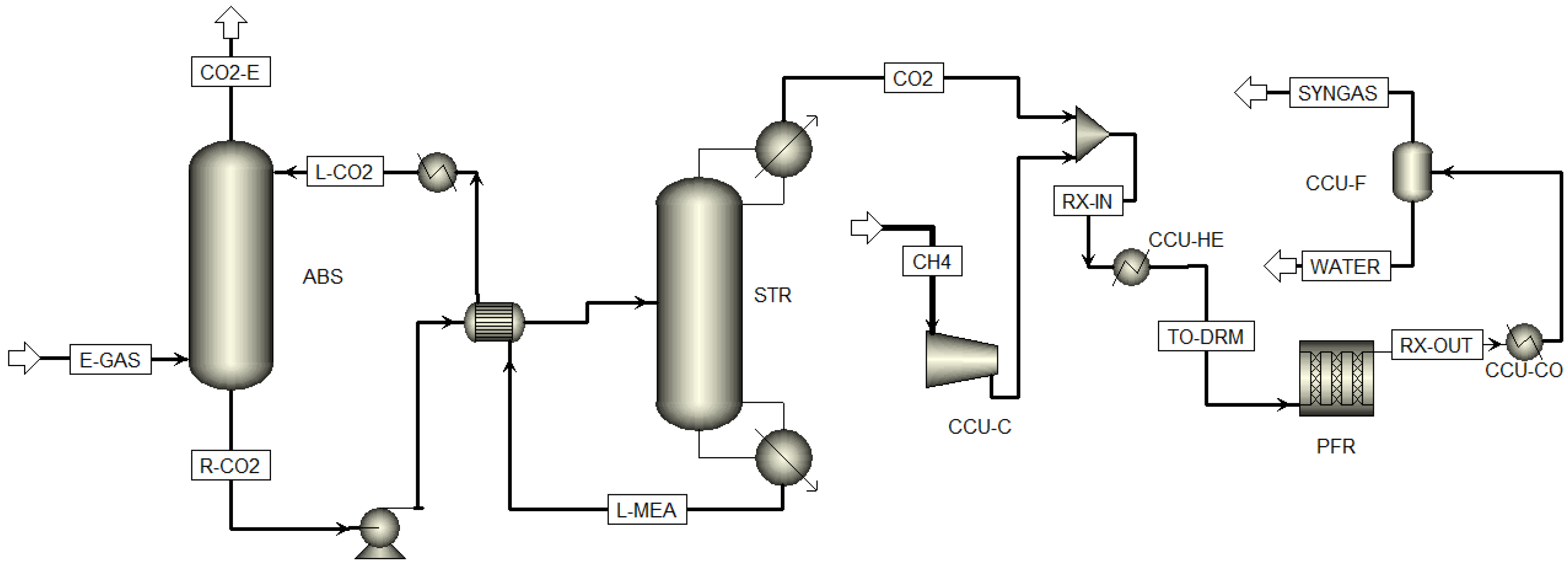
Figure 3 shows the flowsheet of the CCU process to produce syngas by dry reforming of methane (DRM) based on carbon. For the simulation of the carbon capture process, the kinetic model of Zhang et al. based on experimental data [45] and the NRTL thermodynamic model were used. In the process, the stream of combustion gases (E-GAS) is fed to an absorber (ABS) where 90% of the carbon is captured using a monoethanolamide (MEA) solution as absorbent (35 wt%). Then, the stream from the absorber (R-CO2) is heated and fed to a stripping unit (STR). Finally, the CO2 stream with a carbon molar concentration of 98% is obtained in the STR dome, and a stream that recovers MEA (L-MEA) exits as a bottom product, which is recirculated to the absorber.
The DRM plant simulation was based on the parameters reported by Gagadharan et al. [46] and the kinetic models given by Barroso-Quiroga and Castro-Luna [47]. For syngas production, methane (CH4) and CO2 streams (TO-DRM) are mixed, heated to 599 °C, and fed to a PFR reactor. The outlet stream from the reactor is cooled to 25 °C and sent to a flash unit, from which streams of syngas and water are obtained. The main parameters for the simulation of the CCU system are given in Table 2.

2.2. Energy Analysis

The net power output (nP) of the integrated BGCC-CCU-ORC system was calculated from the gross power generated from the gas, steam, and ORC turbines, minus the process energy consumption (Pcon),
nP = Gross power − Pcon,
In Equation (1), Pcon includes the energy consumption of the equipment units of the BGCC, CCU, and ORC components, as well as the energy losses caused by the steam extraction for the CCU operation.
To improve the system performance, energy integration was considered between the working fluid, the waste streams from the steam turbine system, and the outlet stream from the PFR (RX-OUT). For the heat integration with the combustion gases, a reduction in the water flow to the recovery boiler (ECON and EVAP) was set to yield a temperature of the combustion gases between 90 and 110 °C. The water flow rate was then optimized within this temperature range to detect the conditions under which the highest net power was obtained, which accounts for the balance between the reduction in water flow to the recovery boiler and the lower energy produced by the turbine.

2.3. Environmental and Economic Analysis

The environmental analysis for the integrated system considered the equivalent carbon emissions of the process. Total greenhouse gas emissions were calculated from the total carbon equivalent emissions minus the amount of carbon capture.
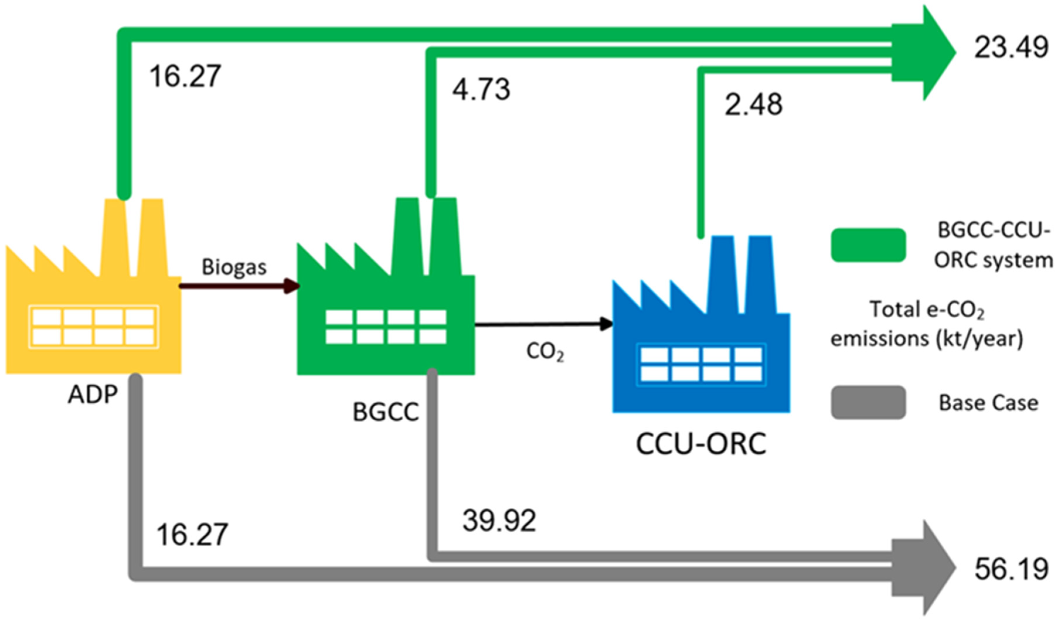
The analysis considers the life cycle scheme shown in Figure 4, which includes the biogas production in addition to the BGCC power plant, the ORC process, and the CCU technology. Data of emission for the biogas production process were taken from the Ecoinvent database for an anaerobic digestion plant [48], and those for the BGCC power plant and the CCU were estimated via simulations. For the ORC, two percent yearly losses of the working fluid were set, as reported by Gerber and Maréchal [49]. Values of equivalent carbon grams for greenhouse gases were taken from the IPCC report [50].
For the economic analysis, equipment costs reported by Kang et al. [27] for the combined cycle system were used and complemented with cost estimation of the CCU and ORC components, which were then used to estimate total capital investment, operating costs for each alternative, and the product sales price needed to provide a fifteen percent return on investment.

2.4. Inherent Safety Analysis

Process safety is commonly addressed once the system has been designed, for which process changes aiming to improve this component become rather limited. The inclusion of inherent safety principles during the design stage of the process provides an effective and useful way to design systems with lower risk for undesirable incidents during the operation of the process. Several indices have been developed that can be included as part of the process design [51]. To assess inherent safety, the fire and explosion damage index (FEDI) was used in this work. The calculation of the FEDI is based on the estimation of four energy factors, as summarized in this section.
The first factor accounts for chemical energy,
F1 = 0.1M (Hc/3.148),
where M is the mass flow in kg/s and Hc is the heat of combustion in J/mol.
Factors F2 and F3 are related to physical energy,
F2 = (1.304 × 10⁻³)(PP)(V),
F3 = (1 × 10⁻³)(1/(T + 273)) (PP − VP)2 (V),
where PP and VP are the operating and vapor pressures in kPa, V is the volume of the vessel in m3, and T is the operating temperature in °C.
The fourth energy factor, F4, applies to reactor units,
F4 = M (Hrxn/3.148),
where Hrxn is the heat of reaction in kJ/kg.
Penalty factors are used to account for extreme operating conditions and volume vessels, which are then used to calculate a hazard potential (HP). For the details on the calculations and use of such penalty factors, see Khan and Abbasi [52], Castillo-Landero et al. [53], and Ortiz-Espinoza et al. [54].
Finally, the FEDI metric is calculated with Equation (6).
FEDI = 4.76 ((HP)1/3)
Parameters for FEDI calculations for the working fluids are given in Table 3. Also, the calculation of vapor pressure was calculated with the Antoine equation for each component, and the volume of the equipment was calculated with the parameters obtained from the Aspen Plus simulations. It should be noticed that units of the steam turbine section and other small equipment units such as mixers, pumps, and splitters were not considered for this analysis.

3. Results and Discussion

Table 4 gives the major results from the Aspen simulation of the BGCC power plant (compared in the table to those reported by Kang et al. [27]). Values of 5.11 MW and 1.24 MW for the gas and steam turbine power were obtained, which can provide a net power of 6.26 MWe and a plant efficiency of 37.2%. Energy, environmental, economic, and inherent safety analyses were carried out, and they are reported in the following subsections.

3.1. Results from the Energy Analysis

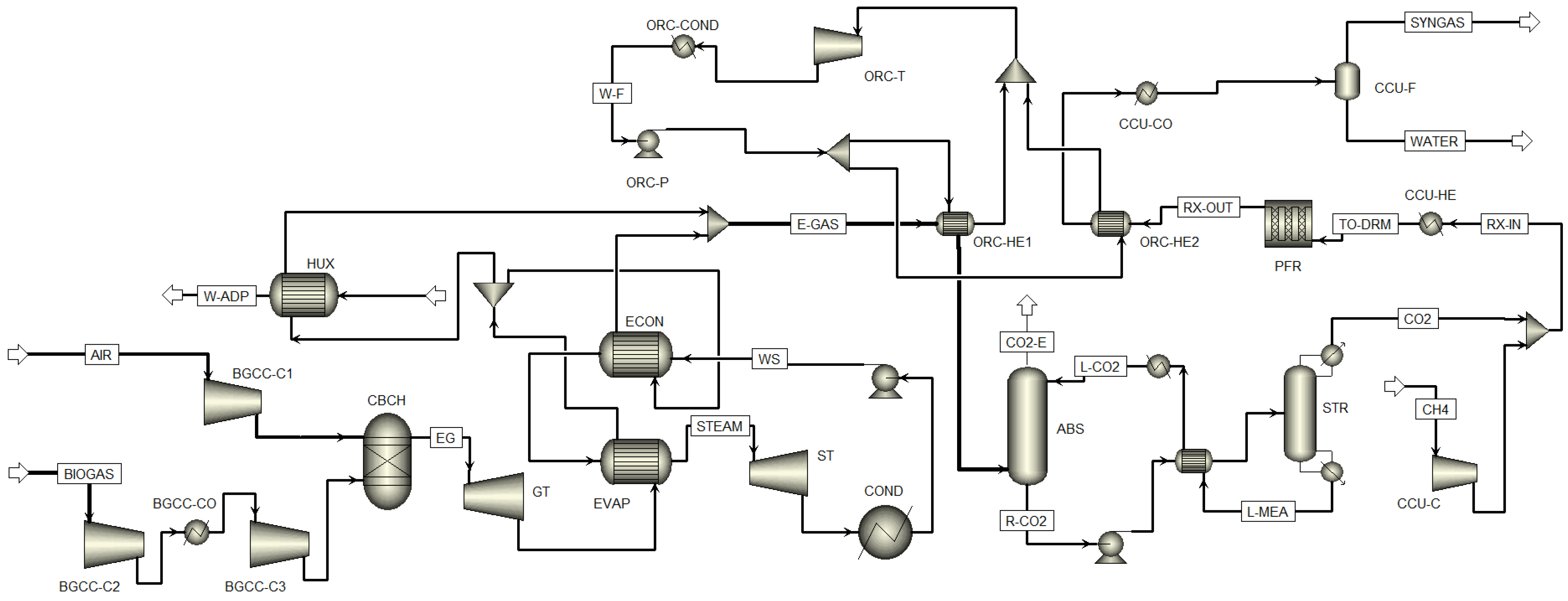
The flowsheet for the integrated BGCC-CCU-ORC system is shown in Figure 5. The match between all technologies is set mainly by the ORC heat exchangers (ORC-HE1 and ORC-HE2). In the ORC-HE1 exchange, the waste heat of the E-GAS stream is transferred to the working fluid of the ORC, after which E-GAS is fed to the CCU system, where carbon is captured and used to produce syngas. The energy analysis assumed that the electrical energy requirements and the carbon capture steam for CO2 desorption were met by the BGCC power plant. Under these conditions, 4.47 MW were obtained for the reboiler duty and 0.3895 MW for the operation of pumps and compressors for the CCU. The power of ST decreased from 1.241 to 0.53 MW because of the steam extraction needed to produce 5.16 MW of net power output for the BGCC-CCU system, which corresponds to a reduction (energy penalty) of 1.1 MW, or 17.5%, compared to the stand-alone power plant.
The values of electricity produced for the system coupled with ORCs for each working fluid, keeping the generation from gas and steam turbines fixed, are reported in Table 5. It can be observed that the generation of electricity in the ORC produces a reduction in the CCU energy penalty by 28 to 33%. From the three working fluids analyzed in this work, R717 provided the highest electricity generation, while the lowest value was obtained from the R1234yf alternative. In addition to the energy penalty reduction, the integrated system shows a net power increase between 6 and 6.8% with respect to the BGCC-CCU process.
In terms of the amount of electricity that could meet the needs of a given population as a social benefit, and specifically using the reported energy consumption in Mexico of 2412 kWh per capita by the International Energy Agency [56], one can estimate that the amount of electricity produced by the integrated system could meet the needs of 18,000–19,000 people/year, depending on the selected ORC working fluid.

3.2. Environmental and Economic Implications

For the stand-alone BGCC power plant, an amount of 39.92 kt/year of carbon emissions was obtained from the Aspen simulations, which corresponds to a value of 0.838 CO2 kg/kWh. Comparison with conventional technologies showed that such emissions are 119% higher than those obtained from a combined cycle power plant operating with natural gas and 28.9% lower than those from a coal-fired power plant. The higher value of emissions for the BGCC compared with the natural gas power plant is due to the biogas composition; however, such emissions are considered with negative values in a life cycle calculation like the one carried out here because of their non-fossil nature. As a result, the implementation of a carbon capture technology at the BGCC power plant can significantly reduce direct air emissions compared with conventional processes, as shown in Figure 6.
Figure 7 shows the emissions from the system as estimated by Aspen Plus simulations for the base case and the integrated BGCC-CCU-ORC system. One can observe that e-CO2 emissions are reduced from 39.92 kt/year based on the BGCC single unit to 7.21 kt/year for the integrated system (equivalent to an 82% reduction). If one considers a life cycle analysis, the ADP unit that produces the biogas fed into the system needs to be added. The ADP component produces 16.27 kt/year of e-CO2 emissions. The savings provided by the integration of the BGCC-CCU-ORC system amount to 32.7 kt/year, or 58.2%, with respect to the ADP-BGCC system. It should be noted that the annual leaks assumed in the ORC result in a minor environmental impact because of the low flow and GWP of the working fluids.
For the economic analysis, a BGCC power plant equipment cost of 20.89 million USD (taken from Kang et al. [27] and updated to 2024) was used. For the CCU, a value of 10.43 million USD was estimated, which corresponds to an increase of 49% compared with the stand-alone BGCC. The estimated equipment costs for each ORC alternative varied slightly, from 2.44 million USD based on the R1234yf alternative to 2.63 million USD for the R717.
For the total capital investment (TCI), other items such as consulting and design, installation, permits and inspection, and contingency costs were taken as 30% of the equipment cost. TCI values differed by about 0.19 million USD among all the alternatives, with R717 showing the highest value (44.18 million USD, which is 62% higher than the TCI reported by Kang et al. [27] for the BGCC power plant without CCU and an ORC).
For the annual production cost, values of 0.0078 USD/kWh for operation and maintenance, 0.364 USD/ton for feedstock transportation, and 0.015 USD/kWh for pretreatment costs were used (values taken from Kang et al. [27] and updated to the year 2024). These values were used to calculate the price at which the syngas product from the process should be sold to obtain a 15% return on investment. Based on an electricity price of 0.17, which can be viewed as a competitive alternative based on reported regional USA prices in March 2025 that ranged from 0.317 to 0.061 USD/kWh for the industrial sector [57], a syngas selling price was estimated as 0.24 USD/kg, with a payback period of 5.34 years.

3.3. Inherent Safety Implications

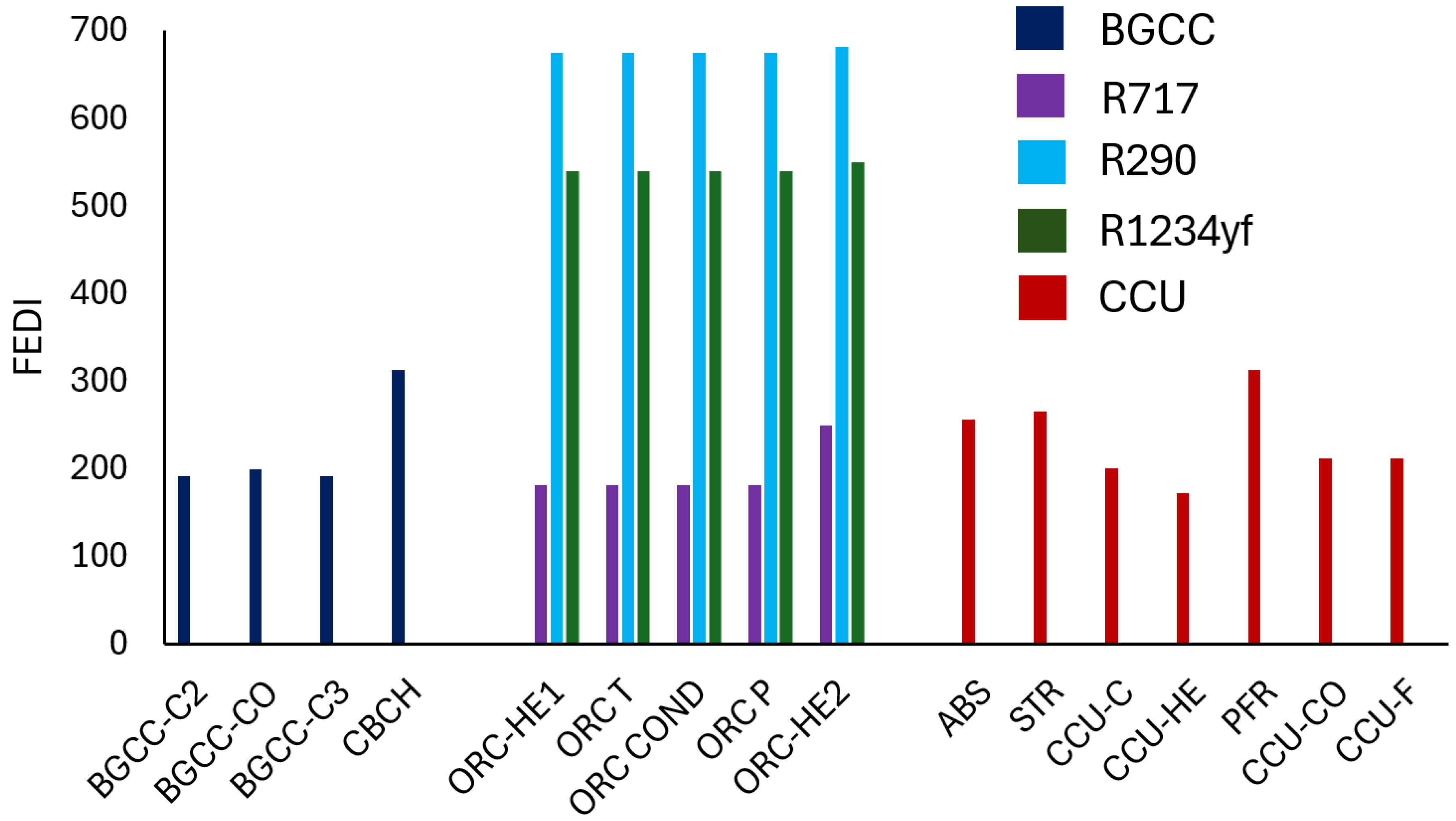
Figure 8 shows the FEDI results for each piece of equipment in the three sections of the process. We take the highest FEDI value as a risk metric for each section of the process, as in Castillo-Landero et al. [53]. For the first section of the process, one can notice that the risk of the stand-alone BGCC power plant is related to the combustion chamber, with a FEDI value of 311, rated as a hazardous process.
In the ORC section, the addition of the working fluid affects the process’s inherent safety differently. The highest risk is associated with the use of the R290 working fluid, which makes the process extremely hazardous given the FEDI value above 670. The R717 fluid provides the best choice from inherent safety considerations, since the process falls into a classification of hazardous according to the FEDI value of 240 in the ORC-HE2 unit.
For the CCU area, the inherent safety analysis results in a similar classification to that of the first section of the process, with the process risk associated in this case to the operation of the DRM reactor.
If one views the whole process, it is noticeable that the addition of working fluids can affect the inherent safety significantly. The process can be taken to a high-risk level with the R290 fluid, while the use of R717 has a minor effect on the process risk. From an overall analysis, the R717 working fluid could be rated as the most convenient choice from the set of fluids considered in this work from energy, sustainability, and inherent safety considerations.
It should be noted that the inherent safety analysis presented here applies during the initial design stage of the process. Therefore, the details of actions such as mitigation, control loops, and so forth would come into place when the final design and/or the process is ready for operation. Such actions would be simpler and less expensive if the process had lower risk levels provided by a more favorable design and operating conditions given by a more suitable inherent safety metric.

3.4. Energy, Environment, Economics, and Safety System Performance Comparison

Figure 9 shows a summary of the metrics evaluated in this work. As can be observed, the proposed system can achieve significant social, environmental, and economic benefits due to the combination of key technologies that take advantage of the use of resources such as bio-waste materials and biogas. The resulting structure can produce electricity and syngas with a reduction of 58.2% of e-CO2 emissions (CCU technology), without increasing the risk classification of the process with the R-717 ORC working fluid and reducing CUU energy penalty with the use of waste heat as an energy resource that contributes to the reduction in the process energy requirements. The R-717 working fluid turned out to be the best selection from the three options considered in this work because it has the lowest values of latent heat of vaporization, heat of combustion, and NFPA flammability.
In terms of energy and capital cost, the net power has a reduction of 5.75%, and the TCI increases 62.7% for the integrated system compared to the stand-alone BGCC.

4. Conclusions

The design and operation of power plants is mostly based on fossil fuels, which, in exchange for their economic performance, have driven a rising concern because of their environmental implications. We have analyzed in this work the use of bioresources in the form of biogas as part of the search for solutions to the use of fossil fuels. The study has taken as a basis the operation of a 6.3 MW power plant, with the objective of assessing the integration of CCU technologies and ORCs within a multi-objective formulation that included economic, environmental, and inherent safety components. For the operation of ORCs, three different working fluids (R1234yf, R290, and R717) were considered. Economic metrics such as total annual costs and payback periods, energy metrics such as net power produced, environmental metrics such as equivalent CO2 emissions, and inherent safety metrics such as the Fire and Explosion Damage Index were used. Such metrics were calculated for an integrated BGCC-ORC-CCU system and compared with those for the stand-alone BGCC power plant. It was shown that the use of biogas as part of a combined cycle power plant can effectively be integrated to contribute to the process economics by producing syngas as a value-added product. Also, the integration of BGCC, CCU, and ORC technologies can contribute to the design of a more sustainable system by reducing e-CO2 emissions by more than 80% with respect to the BGCC power plant. Furthermore, a life cycle analysis showed that even by including the biogas generation unit, such emissions show a reduction above 50%. The performance of the system with respect to conventional technologies based on coal or natural gas showed significant environmental benefits, thus providing a further incentive for its consideration.
Finally, the inherent safety analysis showed that the process risk depends noticeably on the choice of the working fluid for the ORC. The results showed that ratings of the process risk could fall under hazardous or extremely hazardous classifications depending on the working fluid and that the R717 provided the lowest risk to the process. This aspect, together with its benefits from energy and sustainability considerations, would make it the preferred working fluid from the options considered here. The systems analysis used in this work under a multi-objective formulation approach allowed a suitable overall assessment of the performance of the integrated processing system.

Author Contributions

Conceptualization, A.J.-G. and F.N.-R.; data curation, G.G.E.-P.; formal analysis, G.G.E.-P. and A.J.-G.; investigation, G.G.E.-P.; methodology, A.J.-G. and G.G.E.-P.; software, G.G.E.-P.; supervision, F.N.-R.; validation, G.G.E.-P.; writing—original draft preparation, G.G.E.-P.; writing—review and editing, F.N.-R. and A.J.-G. All authors have read and agreed to the published version of the manuscript.

Funding

The research did not receive any specific grant from funding agencies in the public, commercial, or not-for-profit sectors.

Data Availability Statement

The original contributions presented in this study are included in the article. Further inquiries can be directed to the corresponding author(s).

Acknowledgments

One of the authors (Gerardo G. Esquivel-Patiño) received a postdoctoral fellowship from CONAHCYT, Mexico, during the development of this project.

Conflicts of Interest

The authors declare no conflicts of interest.

Abbreviations

The following abbreviations are used in this manuscript:
ADPAnaerobic digestion plant
BGCCBiogas combined cycle
CCUCarbon capture and utilization
DRMDry reforming of methane
FEDIFire and explosion damage index
MEAMonoethanolamine
ORCOrganic Rankine cycle
TCITotal capital investment

References

  1. Deublein, D.; Steinhauser, A. Biogas from Waste and Renewable Resources: An Introduction, 2nd ed.; Wiley VCH Verlag: Weinheim, Germany, 2011. [Google Scholar]
  2. Pérez-Uresti, S.I.; Martín, M.; Jiménez-Gutiérrez, A. Superstructure approach for the design of renewable-based utility plants. Comput. Chem. Eng. 2019, 123, 371–388. [Google Scholar] [CrossRef]
  3. International Energy Agency (IEA). 2025. Available online: https://www.iea.org/reports/global-energy-review-2025/co2-emissions (accessed on 25 September 2025).
  4. Zhi, K.; Li, Z.; Wang, B.; Klemeš, J.J.; Guo, L. A review of CO2 utilization and emissions reduction: From the perspective of the chemical engineering. Process Saf. Environ. Prot. 2023, 172, 681–699. [Google Scholar] [CrossRef]
  5. Song, Y.; Ahmad, S.F.; Abou Houran, M.; Agrawal, M.K.; Kumar Nutakki, T.U.; Siddiqui, M.R.; Albani, A.; Su, O. Multi-variable study of a novel multigeneration system using biogas separation unit and LNG cold energy utilization, producing electricity, cooling, heat, fresh water, liquid CO2, biomethane, and methanol. Process Saf. Environ. Prot. 2023, 189, 616–638. [Google Scholar] [CrossRef]
  6. Wu, C.; Huang, Q.; Xu, Z.; Sipra, A.T.; Gao, N.; Vandenberghe, L.P.d.S.; Vieira, S.; Soccol, C.R.; Zhao, R.; Deng, S.; et al. A comprehensive review of carbon capture science and technologies. Carbon Capture Sci. Technol. 2024, 11, 100178. [Google Scholar] [CrossRef]
  7. International Energy Agency (IEA). 2025. Available online: https://www.iea.org/energy-system/renewables/bioenergy (accessed on 25 September 2025).
  8. Calise, F.; Cappiello, F.L.; Cimmino, L.; Napolitano, M.; Vicidomini, M. Analysis of the Influence of Temperature on the Anaerobic Digestion Process in a Plug Flow Reactor. Thermo 2022, 2, 92–106. [Google Scholar] [CrossRef]
  9. Eller, F.; Ehde, P.M.; Oehmke, C.; Ren, L.; Brix, H.; Sorrell, B.K.; Weisner, S.E.B. Biomethane Yield from Different European Phragmites australis Genotypes, Compared with Other Herbaceous Wetland Species Grown at Different Fertilization Regimes. Resources 2020, 9, 57. [Google Scholar] [CrossRef]
  10. Zhang, G.; Li, Y.; Dai, Y.J.; Wang, R.Z. Design and analysis of a biogas production system utilizing residual energy for a hybrid CSP and biogas power plant. Appl. Therm. Eng. 2016, 109, 423–431. [Google Scholar] [CrossRef]
  11. Anika, O.C.; Nnabuife, S.G.; Bello, A.; Okoroafor, E.R.; Kuang, B.; Villa, R. Prospects of low and zero-carbon renewable fuels in 1.5-degree net zero emission actualisation by 2050: A critical review. Carbon Capture Sci. Technol. 2022, 5, 100072. [Google Scholar] [CrossRef]
  12. Liang, P.; Guo, Y.; Chauhdary, S.T.; Agrawal, M.K.; Ahmad, S.F.; Ahmad, A.Y.A.B.; Ifseisi, A.A.; Ji, T. Sustainable development and multi-aspect analysis of a novel polygeneration system using biogas upgrading and LNG regasification processes, producing power, heating, fresh water and liquid CO2. Process Saf. Environ. Prot. 2024, 183, 417–436. [Google Scholar] [CrossRef]
  13. Tian, H.; Chen, X.; Ahmad, S.F.; Agrawal, M.K.; Seikh, A.H.; Shah, N.A.; Su, Q. Modeling and 4E analysis of a new combined cooling, heating, and power energy system based on biogas combustion and hot oil for heat supply. Process Saf. Environ. Prot. 2024, 184, 1484–1502. [Google Scholar] [CrossRef]
  14. Tsita, K.G.; Kiartzis, S.J.; Ntavos, N.K.; Pilavachi, P.A. Next generation biofuels derived from thermal and chemical conversion of the Greek transport sector. Therm. Sci. Eng. Prog. 2020, 17, 100387. [Google Scholar] [CrossRef]
  15. Agustini, C.B.; Spier, F.; da Costa, M.; Gutterres, M. Biogas production for anaerobic co-digestion of tannery solid wastes under presence and absence of the tanning agent. Resour. Conserv. Recycl. 2018, 130, 51–59. [Google Scholar] [CrossRef]
  16. Kaushal, R.; Sandhu, S.; Soni, M.K. Anaerobic co-digestion of food waste, algae, and cow dung for biogas yield enhancement as a prospective approach for environmental sustainability. Sustain. Energy Technol. Assess. 2022, 52, 102236. [Google Scholar] [CrossRef]
  17. Silva, C. Greenhouse Gas Emission Assessment of Simulated Wastewater Biorefinery. Resources 2021, 10, 78. [Google Scholar] [CrossRef]
  18. Wang, Y.; Zhang, Y.; Li, J.; Lin, J.G.; Zhang, N.; Cao, W. Biogas energy generated from livestock manure in China: Current situation and future trends. J. Environ. Manag. 2021, 297, 113324. [Google Scholar] [CrossRef]
  19. Guo, M.; Wu, C.; Chapman, S.; Yu, X.; Vinestock, T.; Hastings, A.; Smith, P.; Shah, N. Advances in biorenewables-resource-waste systems and modelling. Carbon Capture Sci. Technol. 2023, 9, 100142. [Google Scholar] [CrossRef]
  20. Frijns, J.; Hofman, J.J.; Nederlof, M. The potential of (waste) water as energy carrier. Energy Convers. Manag. 2013, 65, 365–373. [Google Scholar] [CrossRef]
  21. Global Methane Initiative (GMI). The U.S. Government’s Global Methane Initiative Accomplishments; Annual Report December 2013; Global Methane Initiative: Washington, DC, USA, 2013; pp. 1–16. [Google Scholar]
  22. Wang, Y.; Fang, M.; Lou, Z.; He, H.; Guo, Y.; Pi, X.; Wang, Y.; Yin, K.; Fei, X. Methane emissions from landfills differentially underestimated worldwide. Nat. Sustain. 2024, 7, 496–507. [Google Scholar] [CrossRef]
  23. dos Santos, I.F.S.; Vieira, N.D.B.; Barros, R.M.; Filho, G.L.T.; Soares, D.M.; Alves, L.V. Economic and CO2 avoided emissions analysis of WWTP biogas recovery and its use in a small power plant in Brazil. Sustain. Energy Technol. Assess. 2016, 17, 77–84. [Google Scholar] [CrossRef]
  24. Kythavone, L.; Chaiyat, N. Life cycle assessment of a very small organic Rankine cycle and municipal solid waste incinerator for infectious medical waste. Therm. Sci. Eng. Prog. 2020, 18, 100526. [Google Scholar] [CrossRef]
  25. Li, H.; Tan, Y.; Ditaranto, M.; Yan, J.; Yu, Z. Capturing CO2 from biogas plants. Energy Procedia 2017, 114, 6030–6035. [Google Scholar] [CrossRef]
  26. Mondol, J.D.; Carr, C. Techno-economic assessments of advanced Combined Cycle Gas Turbine (CCGT) technology for the new electricity market in the United Arab Emirates. Sustain. Energy Technol. Assess. 2017, 19, 160–172. [Google Scholar] [CrossRef]
  27. Kang, J.K.; Kang, D.W.; Kim, T.S.; Hur, K.B. Comparative economic analysis of gas turbine-based power generation and combined heat and power systems using biogas fuel. Energy 2014, 67, 309–318. [Google Scholar] [CrossRef]
  28. Michaelides, E.E. Power and Energy Requirements for Carbon Capture and Sequestration. Thermo 2025, 5, 8. [Google Scholar] [CrossRef]
  29. Roumpedakis, T.C.; Fostieris, N.; Braimakis, K.; Monokrousou, E.; Charalampidis, A.; Karellas, S. Techno-Economic Optimization of Medium Temperature Solar-Driven Subcritical Organic Rankine Cycle. Thermo 2021, 1, 77–105. [Google Scholar] [CrossRef]
  30. Ebrahimi, A.; Ghorbani, B.; Ziabasharhagh, M. Exergy and economic analyses of an innovative integrated system for cogeneration of treated biogas and liquid carbon dioxide using absorption–compression refrigeration system and ORC/Kalina power cycles through geothermal energy. Process Saf. Environ. Prot. 2022, 158, 257–281. [Google Scholar] [CrossRef]
  31. Raghulnath, D.; Saravanan, K.; Mahendran, J.; Ranjith-kumar, M.; Lakshmanan, P. Analysis and optimization of organic Rankine cycle for IC engine waste heat recovery system. Mater. Today Proc. 2020, 21, 30–35. [Google Scholar] [CrossRef]
  32. Kong, R.; Deethayat, T.; Asanakham, A.; Kiatsiriroat, T. Performance analysis of biomass boiler-organic Rankine cycle with assisted cascade heat pump for combined heat and power generation including exergy-costing. Sustain. Energy Technol. Assess. 2022, 52, 102125. [Google Scholar] [CrossRef]
  33. Yağlı, H.; Koç, Y.; Koç, A.; Gorgülü, A.; Tandiroğlu, A. Parametric optimization and exergetic analysis comparison of subcritical and supercritical organic Rankine cycle (ORC) for biogas fueled combined heat and power (CHP) engine exhaust gas waste heat. Energy 2016, 111, 923–932. [Google Scholar] [CrossRef]
  34. Baccioli, A.; Ferrari, L.; Vizza, F.; Desideri, U. Potential energy recovery by integrating an ORC in a biogas plant. Appl. Energy 2019, 256, 113960. [Google Scholar] [CrossRef]
  35. Aliyu, M.; AlQudaihi, A.B.; Said, S.A.M.; Habib, M.A. Energy, Exergy and Parametric Analysis of a Combined Cycle Power Plant. Therm. Sci. Eng. Prog. 2020, 15, 100450. [Google Scholar] [CrossRef]
  36. Chang, H.; Li, J. A new exergy method for process analysis and optimization. Chem. Eng. Sci. 2005, 60, 2771–2784. [Google Scholar] [CrossRef]
  37. Shen, F.; Wang, M.; Huang, L.; Qian, F. Exergy analysis and multi-objective optimization for energy system: A case study of a separation process in ethylene manufacturing. J. Ind. Eng. Chem. 2021, 93, 394–406. [Google Scholar] [CrossRef]
  38. Fujii, M.; Dou, Y.; Sun, L.; Ohnishi, S.; Maki, S.; Dong, H.; Dong, L.; Chandran, R. Contribution to a low-carbon society from improving exergy of waste-to-energy system by upgrading utilization of waste. Resour. Conserv. Recycl. 2019, 149, 586–594. [Google Scholar] [CrossRef]
  39. Filiz-Tumen-Ozdil, N.; Tantekin, A. Exergy and exergoeconomic assessments of an electricity production system in a running wastewater treatment plant. Renew. Energy 2016, 97, 390–398. [Google Scholar] [CrossRef]
  40. Yang, Z.; Feng, B.; Ma, H.; Zhang, L.; Duan, C.; Liu, B.; Zhang, Y.; Chen, S.; Yang, Z. Analysis of lower GWP and flammable alternative refrigerants. Int. J. Refrig. 2021, 126, 12–22. [Google Scholar] [CrossRef]
  41. Tamburini, F.; Zanobetti, F.; Cipolletta, M.; Bonvicini, S.; Cozzani, V. State of the art in the quantitative risk assessment of the CCS value chain. Process Saf. Environ. Prot. 2024, 191, 2044–2063. [Google Scholar] [CrossRef]
  42. You, C.; Kim, J. Quantitative risk assessment of an amine-based CO2 capture process. Korean J. Chem. Eng. 2020, 37, 1649–1659. [Google Scholar] [CrossRef]
  43. Kajurek, J.; Rusowicz, A.; Grzebielec, A.; Bujalski, W.; Futyma, K.; Rudowicz, Z. Selection of refrigerants for a modified organic Rankine cycle. Energy 2019, 168, 1–8. [Google Scholar] [CrossRef]
  44. Luo, X.; Wang, M.; Chen, J. Heat integration of natural gas combined cycle power plant integrated with post-combustion CO2 capture and compression. Fuel 2015, 151, 110–117. [Google Scholar] [CrossRef]
  45. Zhang, Y.; Chen, H.; Chen, C.C.; Plaza, J.M.; Dugas, R.; Rochelle, G.T. Rate-based process modeling study of CO2 capture with aqueous monoethanolamine solution. Ind. Eng. Chem. Res. 2009, 48, 9233–9246. [Google Scholar] [CrossRef]
  46. Gangadharan, P.; Kanchi, K.C.; Lou, H.H. Evaluation of the economic and environmental impact of combining dry reforming with steam reforming of methane. Chem. Eng. Res. Des. 2012, 90, 1956–1968. [Google Scholar] [CrossRef]
  47. Barroso-Quiroga, M.M.; Castro-Luna, A.E. Kinetic analysis of rate data for dry reforming of methane. Ind. Eng. Chem. Res. 2007, 46, 5265–5270. [Google Scholar] [CrossRef]
  48. Ecoinvent 3.3. Dataset Documentation. 2009. Available online: https://v371.ecoquery.ecoinvent.org/Search/Index (accessed on 14 August 2024).
  49. Gerber, L.; Maréchal, F. Environomic optimal configurations of geothermal energy conversion systems: Application to the future construction of Enhanced Geothermal Systems in Switzerland. Energy 2015, 45, 908–923. [Google Scholar] [CrossRef]
  50. IPCC. GHG Lifetimes and GWPs. 2014. Available online: https://climatechangeconnection.org/wp-content/uploads/2014/08/GWP_AR4.pdf (accessed on 24 September 2024).
  51. Roi, N.; Eljack, F.; Jiménez-Gutiérrez, A.; Zhang, B.; Thiruvenkataswamy, P.; El-Halwagi, M.; Mannan, M.S. A review of safety indices for process design. Curr. Opin. Chem. Eng. 2016, 14, 42–48. [Google Scholar] [CrossRef]
  52. Khan, F.I.; Abbasi, S.A. Multivariable hazard identification and ranking system. Process Saf. Prog. 1998, 17, 157–170. [Google Scholar] [CrossRef]
  53. Castillo-Landero, A.; Ortiz-Espinoza, A.P.; Jiménez-Gutiérrez, A. A process intensification methodology including economic, sustainability and inherent safety considerations. Ind. Eng. Chem. Res. 2019, 58, 6080–6092. [Google Scholar] [CrossRef]
  54. Ortiz-Espinoza, A.P.; Jiménez-Gutiérrez, A.; El-Halwagi, M.M.; Kazantzis, N.K.; Kazantzi, V. Comparison of safety indexes for chemical processes under uncertainty. Process Saf. Environ. Prot. 2021, 148, 225–236. [Google Scholar] [CrossRef]
  55. National Institutes of Health Database (NIH). 2024. Available online: https://pubchem.ncbi.nlm.nih.gov/ (accessed on 8 September 2024).
  56. International Energy Agency (IEA). 2023. Available online: https://data.worldbank.org/indicator/EG.USE.ELEC.KH.PC?most_recent_year_desc=false&view=map (accessed on 8 June 2025).
  57. Energy Information Administration (EIA). 2024. Available online: https://www.eia.gov/electricity/monthly/epm_table_grapher.php?t=epmt_5_6_a (accessed on 13 November 2024).
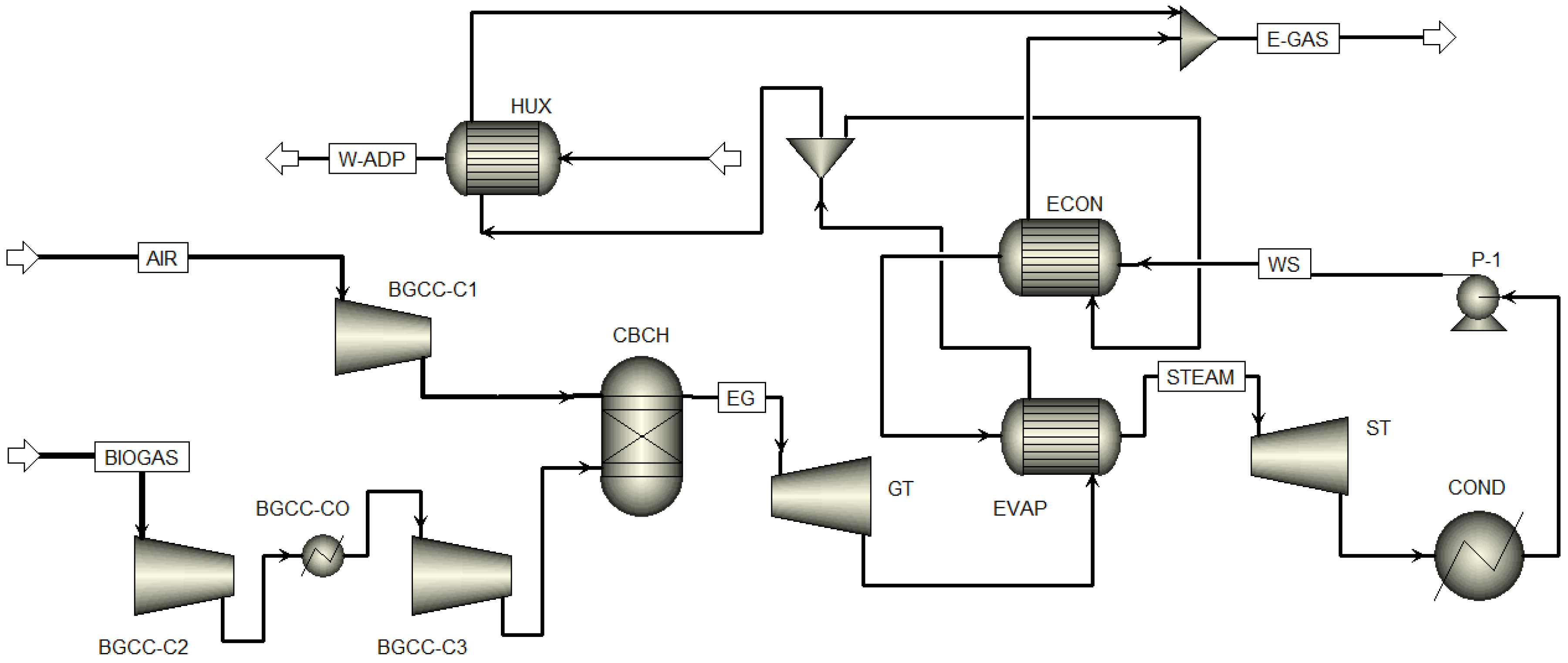
Figure 1. Flowsheet of the BGCC power plant showing the integration of thermodynamic cycles.
Thermo 05 00043 g001
Figure 2. Flowsheet of the ORC showing its individual components.
Thermo 05 00043 g002
Figure 3. Flowsheet of the CCU process. CO2 is used together with methane to produce syngas.
Thermo 05 00043 g003
Figure 4. Scheme for carbon emissions and net power output estimations for the integrated system.
Thermo 05 00043 g004
Figure 5. Flowsheet of the integrated BGCC-CCU-ORC system.
Thermo 05 00043 g005
Figure 6. Carbon emissions to air comparison between the proposed system and conventional technologies. Values for conventional technologies were taken from Ecoinvent [48].
Thermo 05 00043 g006
Figure 7. Total carbon emissions for a life cycle analysis in which the ADP unit is integrated into the BGCC and BGCC-CCU-ORC systems.
Thermo 05 00043 g007
Figure 8. FEDI values for each section unit of the integrated system and working fluid.
Thermo 05 00043 g008
Figure 9. Summary of the metrics evaluated for the stand-alone plant and the integrated system. FEDI values are given in the right-hand vertical axis.
Thermo 05 00043 g009
Table 1. Parameters for the simulations of the BGCC/ORC system.
ParameterValueUnits
Biogas flow0.8346kg/s
Biogas methane composition65%vol
Air flow21.19kg/s
Gas turbine (GT) outlet pressure1.07bar
Steam inlet conditions to the turbine180/9.8°C/bar
Steam turbine (ST) outlet pressure0.1275bar
Evaporator (ORC-HE) outlet temperature80°C
ORC condenser outlet temperature30°C
Table 2. Parameters for the simulations of the CCU system.
ParameterValueUnits
Lean amine inlet conditions5.003/34.95bar/°C
Absorber pressure1.5/10bar/stages
Rich amine inlet conditions1.5/10bar/°C
Stripper pressure2.4/10bar/stages
CO2 flow1.27kg/s
CH4 flow0.46kg/s
PFR operating conditions1.97/873bar/°K
Heater (CCU-HE) outlet temperature873°K
Cooler (CCU-CO) outlet temperature25°C
Flash (CCU-) operating conditions1/25bar/°C
Table 3. Properties of working fluids for the FEDI calculation.
ParameterUnitsR1234yfR290R717
Heat of CombustionkJ/mol1083−2220382.8
Autoignition Temperature°C405450651
NFPA Flammability-241
NFPA Reactivity-000
Flash Point°C114−94132
Source: National Institutes of Health [55].
Table 4. Results from stand-alone BGCC power plant simulation compared to reported data.
ParameterUnitsThis WorkKang et al. [27]
Biogas fluxkg/s0.83460.8346
Air fluxkg/s21.1921.19
Combustion gases temperature°C1017.51104
Gas turbine (GT) net powerMWe5.025.24
Steam turbine (ST) net powerMWe1.2441.165
Combined cycle net powerMWe6.266.405
Plant efficiencyPercent37.238
Table 5. Results from the energy analysis for each working fluid.
ParameterUnitsR1234yfR290R717
Gas turbine net powerkWe502050205020
Steam turbine net powerkWe530530530
ORC net powerkWe313329355
BGCC-CCU-ORC system net powerkWe586358795905
Efficiency%34.834.9435.01
Disclaimer/Publisher’s Note: The statements, opinions and data contained in all publications are solely those of the individual author(s) and contributor(s) and not of MDPI and/or the editor(s). MDPI and/or the editor(s) disclaim responsibility for any injury to people or property resulting from any ideas, methods, instructions or products referred to in the content.