Abstract
This study systematically investigates the variation in the ceiling flame tilt angle in an immersed tube tunnel under the combined effect of longitudinal ventilation and sidewall smoke extraction. The experimental program considers different longitudinal velocities, various sidewall smoke exhaust rates and multiple relative distances between the fire source and the sidewall exhaust outlet, aiming to comprehensively reveal the flame tilt angle under multi-factor coupling conditions. Experiments were carried out in a reduced-scale tunnel model (6.64 m long, 0.96 m wide and 0.5 m high). A porous gas burner supplied a steady heat release, with its distance from the sidewall exhaust outlet systematically varied. Results indicate that the flame tilt angle decreases as the distance between the fire source and the sidewall exhaust outlet increases. A theoretical model was developed to predict the flame tilt angle by incorporating both the sidewall smoke exhaust rate and the relative fire source–exhaust distance. The model accounts for mass loss due to smoke extraction, estimated from the local longitudinal velocity distribution. Predictions from the proposed model agree well with the experimental data.
1. Introduction
With the rapid expansion of transportation infrastructure in China, immersed tube tunnels—serving as a critical means of crossing rivers and straits—have been extensively implemented in major transportation projects, particularly in regions such as the Guangdong–Hong Kong–Macao Greater Bay Area and the Yangtze River Economic Belt, owing to their distinctive structural advantages and superior traffic capacity. However, the confined and elongated geometry of immersed tunnels makes them highly susceptible to hazardous conditions characterized by high temperatures and dense smoke during fire incidents, thereby posing significant challenges to occupant evacuation and firefighting efforts. In recent years, the combined smoke extraction strategy—integrating longitudinal ventilation with sidewall exhaust systems—has emerged as a key fire safety technology in immersed tunnels due to its enhanced smoke control efficiency.
Major fire incidents, such as those in the Channel Tunnel in 1996, 2006 and 2008, where temperatures exceeded 1000 °C causing structural damage and casualties [1], underscore the severe consequences of tunnel fires. By contrast, the Hong Kong–Zhuhai–Macao Bridge immersed tunnel—the world’s longest—incorporates advanced fire safety standards, including integrated smoke control and suppression systems, greatly enhancing its resilience [2]. These examples highlight that in-depth research on fire safety in immersed tunnels is not only scientifically essential for ensuring the operational safety of large-scale underwater transportation infrastructure, but also critical for preventing substantial economic losses and saving lives.
In recent years, numerous researchers have investigated the flame characteristics beneath the ceiling during fires occurring in elongated and confined spaces, yielding relevant research outcomes. Japanese scholar Kurioka [3] conducted fire experiments involving oil pans in tunnels with horseshoe-shaped and rectangular cross-sections. Further in-depth studies were carried out by setting two different flame tilt angles, denoted as θ1 and θ2, as shown in Figure 1.
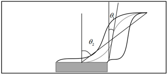
Figure 1.
Definition of flame tilt angle.
Kurioka [3] proposed predictive models for θ1 and θ2, respectively. The proposed formula can be expressed as
where denotes the tunnel cross-sectional area, the oil pan area, B the tunnel width and H the tunnel height. The dimensionless heat release rate is represented by , while is the Froude number. The flame length is expressed as , and represents the distance from the fire source surface to the tunnel ceiling. The ambient air temperature , is taken as 293 K, with the corresponding air density . The specific heat of air at constant pressure is . The longitudinal ventilation velocity is denoted by , and is the gravitational acceleration by . The parameters a, b and c are empirical coefficients, with the value of c determined according to the maximum longitudinal temperature rise beneath the ceiling. Specifically, when , c = −1/3; when , c = 0; when , c = 1/2.
In recent years, extensive research has been conducted on flame shape characteristics in tunnels under longitudinal ventilation. Zisis et al. [4] performed FDS simulations of a 20 MW diesel pool fire inside a 1.5 km rectangular tunnel with a centrally located fire source. A composite correlation for flame length and temperature distribution was established, and the applicability of FDS in reproducing flame inclination was subsequently validated. The results further revealed that once the flame length exceeds the tunnel height, the fire becomes enveloped by the smoke layer. Zhang et al. [5] carried out small-scale experiments (1:10) on twin fire sources under longitudinal ventilation. They reported that the flame angle increases with heat release rate. In still air, the flame angle decreases with increasing fire source spacing, while under longitudinal ventilation, it first decreases and then increases, mirroring the trend in flame height variation. Tang et al. [6] experimentally investigated the effect of strong crosswinds on flame geometry in vehicle tunnel fires. Through analysis of mechanisms such as flame tilt and external combustion, they identified two dimensionless parameters that effectively correlate the experimental data. Yu et al. [7] conducted fire tests in a tunnel model with a wind tunnel and observed that the combined effect of crosswind and baffles significantly modifies the flame length, height and tilt angle, with flame properties stabilizing beyond a critical wind speed (e.g., 3 m/s). Ji et al. [8] proposed a mathematical model for the flame tilt angle, showing that it increases with the distance from the fire source to the wall until reaching a plateau. Kalech et al. [9] employed FDS to simulate various heat release rates, tunnel slopes and longitudinal wind speeds. Their results indicated that for slopes below 1.5° and wind speeds under 1 m/s, buoyancy–inertia balance maintains clear smoke stratification, indirectly influencing flame angle. Xu et al. [10] noted a “back-to-back conical funnel” flame shape in 1:20 wind tunnel tests, with the tilt angle increasing with the momentum flux ratio. Fan et al. [11] observed non-uniform flame tilt distributions due to interaction between crosswind and longitudinal wind in a canyon-type tunnel. Han et al. [12] found that obstructions alter the local flow field, deflecting the flame toward the obstruction. Haddad et al. [13] reported that wall-mounted fires exhibit larger flame angles due to restricted air entrainment. Zhao et al. [14] observed increased fluctuation in flame angle under crosswind disturbance. Sun et al. [15] showed that the flame angle increases exponentially with uphill slope. Chen et al. [16] experimentally studied the effects of baffles (10–40 cm) and crosswinds (0–3 m/s) on an 8 cm pool fire, proposing an empirical model for flame height and inclination. Edalati et al. [17] quantified the coupled effect of slope and wind speed, reporting an increase in flame tilt angle of approximately 5–8° per 10° increase in slope or 1 m/s increase in wind speed. Lanchava et al. [18] demonstrated a nonlinear relationship between critical ventilation velocity and flame tilt angle in inclined tunnels, noting that a minimum velocity of 6 m/s is required to prevent backflow under adverse ventilation conditions, with pressure imbalances amplifying tilt fluctuations. Wang et al. [19] attributed a decrease in flame tilt angle with increasing slope to restricted air entrainment causing flame attachment. Levin et al. [20] found that slopes exceeding 7% may induce flow reversal, leading to abrupt changes in flame tilt and smoke backflow.
Despite these efforts, current theoretical models of tunnel fires remain predominantly focused on single-mode longitudinal ventilation, with limited studies addressing the combined effects of longitudinal ventilation and sidewall exhaust—a configuration already implemented in real-world engineering applications such as the immersed tunnel of the Hong Kong–Zhuhai–Macao Bridge [21]. Figure 2 illustrates the arrangement of sidewall smoke exhaust outlets in a real immersed tube tunnel [22]. There is thus a pressing need to investigate flame tilt behavior under coupled ventilation and extraction conditions.
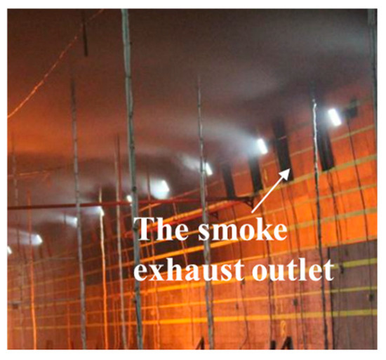
Figure 2.
Sidewall smoke exhaust outlet in the immersed tube tunnel 22.
In this study, a series of experiments were performed in a reduced-scale immersed tunnel to investigate the behavior of the flame tilt angle under the combined influence of sidewall smoke extraction and longitudinal ventilation. Emphasis was placed on the effects of fire source location relative to the exhaust opening and the smoke extraction rate. The results provide valuable experimental data and theoretical insights for optimizing tunnel ventilation and smoke control strategies.
2. Theoretical Model
Building upon Kurioka’s model (Equation (4)), the flame tilt angle can be further adjusted to incorporate the influence of sidewall smoke extraction, as well as the distance between the exhaust outlet and the heat source, as illustrated in Figure 3. According to the principle of mass conservation:
where is the air density (kg/m3), is the smoke density (kg/m3), is the longitudinal wind speed (m/s), is the actual wind speed in the tunnel, Va is the smoke exhaust rate (m3/s).

Figure 3.
A simple theoretical model for predicting the flame tilt angle under the combined effect of sidewall smoke exhaust and longitudinal ventilation.
Considering the approximation of air density, the actual wind speed in the immersed tunnel can be represented as
By substituting Equation (6) into Equation (4), a predictive model for the flame tilt angle is obtained, which explicitly incorporates the influence of the sidewall smoke exhaust rate:
3. Experimental
As shown in Figure 4a,b, the experiments were conducted using a 1:15 scaled tunnel model. The main structure of the model measures 6.64 m in length and 0.96 m in width, and is divided into four standard segments, each 1.66 m long. The lower part of the tunnel is supported by lockable pulley brackets, while the ceiling and floor are constructed using fire-resistant glass fiber boards mounted on steel frames. The tunnel wall without smoke exhaust vents is composed of 12 mm thick fire-resistant glass panels.

Figure 4.
Immersed tunnel test platform. (a) Overall view of the tunnel model, (b) side view of the tunnel model.
Propane was selected as the fuel for this experiment. It was stored in the cylinder in liquid form and regulated by a pressure-reducing valve to maintain a stable and safe supply. After pressure reduction, the propane entered a glass rotameter with a measuring range of 100–1000 L/h for precise flow control before being delivered to the burner. The burner consisted of a square porous plate measuring 10 cm × 10 cm, with 81 uniformly distributed orifices on its surface. Figure 5 presents the glass rotameter and the burner used in this study.
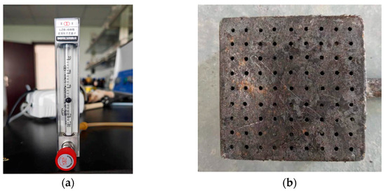
Figure 5.
The heat setting. (a) The glass rotameter, (b) the burner.
The lower heating value of the propane used in this study was 46.3 MJ/kg [23], and the combustion efficiency was assumed to be 1. The propane flow rate was measured by a glass rotameter, and the measured values were corrected to ensure accuracy. Finally, the heat release rate (HRR) was calculated according to Equation (8) [24]. The corresponding HRR for different propane flow rates is summarized in Table 1.
where is the combustion efficiency; is the heat of combustion of propane (MJ/kg); is the density of propane gas (kg/m3), is the compensated volumetric flow rate (m3/h).

Table 1.
Corresponding values of the gas flow rate measured by the rotameter and the resulting heat release rate.
At the left end of the tunnel model, a longitudinal ventilation device with a movable position is installed. The longitudinal ventilation device mainly consists of a frequency conversion control cabinet, a frequency conversion fan and a rectifier device. The wind speed frequency of the variable-frequency fan is adjusted by a frequency converter to supply pressurized air to the interior of the tunnel. The airflow velocity was measured using a high-temperature anemometer, with an accuracy of ± (2% of reading + 0.02 m/s).
The distance between the fire source and the sidewall smoke exhaust outlet is defined as D. High-definition cameras were installed in front of and beside the fire source to capture and record the flame characteristics. The detailed setup of the experimental platform is presented in Figure 6. The specific experimental conditions are shown in Table 2 and Table 3.

Figure 6.
Experimental setup.

Table 2.
Summary of experimental conditions under fixed sidewall smoke exhaust rate.

Table 3.
Summary of experimental conditions under varying sidewall smoke exhaust rate.
The Froude law is applied to build the scale model tunnel and the scaling relationship of some important parameters is shown in Table 4, where s represents entity parameters, m represents model parameters, L is the length (m).

Table 4.
The scaling relationship of some important parameters.
4. Results and Discussion
In this study, the raw experimental videos were first processed using Adobe Premiere Pro to ensure format consistency and compatibility. A 100 s segment corresponding to the steady-state combustion phase was then extracted for each test condition. These video clips were imported into a dedicated flame image-processing tool, and binarization was performed using MATLAB R2020a to clearly distinguish the flame region from the background.
As illustrated in Figure 7 for a heat release rate of 5.74 kW, the longitudinal ventilation velocity significantly influences flame behavior. At any transverse position within the tunnel, the flame tilt angle increases markedly with higher longitudinal wind speeds. When the distance (D) between the fire source and the sidewall exhaust vent is less than 0.48 m and the longitudinal wind speed is 1 m/s, the flame tilts more noticeably compared to a central fire source placement, due to the interaction between sidewall extraction and longitudinal flow. In contrast, when D exceeds 0.48 m, the flame tilt angle becomes smaller than that at the centerline, as the suction effect of the sidewall exhaust diminishes with increasing distance. Under conditions of no longitudinal ventilation, the flame remains nearly symmetric about the fire source centerline. At a longitudinal wind speed of 4 m/s, the effect of D on the flame tilt angle becomes negligible, indicating that high-velocity longitudinal airflow dominates the flame behavior and overwhelms the influence of sidewall extraction.
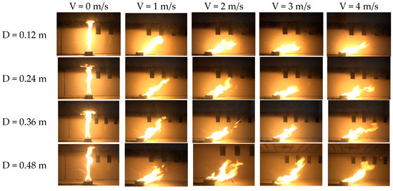
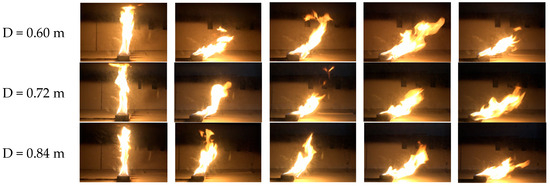
Figure 7.
Combustion flame shape of propane gas fire with the distances between different fire sources and the sidewall smoke exhaust outlets.
Figure 8 presents the variation in the cosine of the flame tilt angle (cos θ) as a function of the distance between the fire source and the sidewall smoke exhaust outlet under different longitudinal wind speeds. As shown in the figure, cos θ decreases progressively with increasing longitudinal wind speed, indicating that the flame tilt angle (θ) increases accordingly. The values of cos θ vary significantly with changes in the distance from the smoke exhaust sidewall, ranging from 0.40 to 0.96. In Figure 8a, corresponding to a heat release rate of 5.74 kW, the maximum value of cos θ is observed when the distance between the fire source and the sidewall exhaust outlet is 0.84 m. This corresponds to the smallest flame tilt angle among all tested positions. A general trend is evident: as the distance from the fire source to the sidewall exhaust outlet increases, cos θ increases, resulting in a smaller flame tilt angle θ. A similar trend is observed in Figure 8b for a heat release rate of 11.47 kW. Again, cos θ reaches its peak at a distance of 0.84 m, indicating the smallest tilt angle at this position. When the distance is less than or equal to 0.36 m, variations in flame tilt angle are minimal. However, greater changes in flame angle occur when the distance exceeds 0.48 m. In Figure 8c, at a heat release rate of 22.95 kW, the trend remains consistent. The maximum cos θ is again recorded at a distance of 0.84 m, corresponding to the smallest tilt angle. Notably, the difference in flame tilt angle between distances of 0.72 m and 0.84 m is relatively small. Overall, across all three heat release rates, the flame tilt angle was found to decrease (corresponding to an increase in cos θ) with increasing distance between the fire source and the sidewall exhaust outlet. Under the same longitudinal wind speed, variations in flame tilt angle are relatively small when the distance is ≤0.60 m, and become more pronounced when the distance is ≥0.72 m.
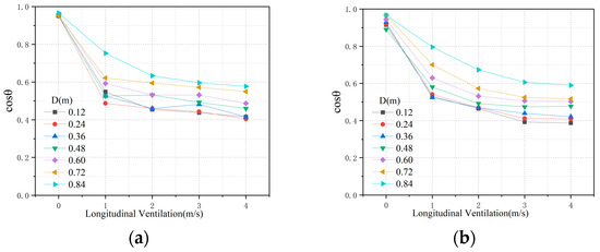
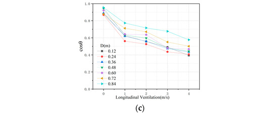
Figure 8.
Cosine of flame angle at different distances between fire source and sidewall smoke exhaust outlet. (a) HRR = 5.74 kW, (b) HRR = 11.47 kW, (c) HRR = 22.95 kW.
Figure 9 illustrates the variation in flame morphology under different sidewall smoke exhaust rates, with the fire source located along the tunnel centerline. The following observations can be drawn: (1) At a heat release rate of 5.74 kW, variations in the sidewall smoke exhaust rate have a negligible effect on the overall flame morphology. However, the flame exhibits a slight contraction, indicating limited sensitivity to exhaust flow at lower fire intensities. (2) At a heat release rate of 11.47 kW, the flame tilt angle gradually decreases with increasing sidewall smoke exhaust rate. The smallest tilt angle is observed at a smoke exhaust rate of 0.0349 m3/s, indicating that increased suction strength enhances the flame’s vertical stability. (3) At a heat release rate of 22.95 kW, the flame directly impinges on the tunnel ceiling and is positioned in front of the sidewall exhaust outlet. At lower exhaust rates (0, 0.0087 m3/s and 0.0175 m3/s), changes in the extraction rate exert minimal influence on flame morphology. However, at higher exhaust rates (0.0262 m3/s and 0.0349 m3/s), the enhanced suction effect pulls the flame closer to the sidewall, resulting in a reduced flame tilt angle. Although the primary function of sidewall smoke exhaust is to facilitate the rapid removal of toxic smoke, the induced suction flow can also alter flame trajectory, drawing it laterally toward the exhaust outlet. This deflection may influence the flame spread pattern and potentially cause localized temperature increases and instability in flame propagation direction within the tunnel.
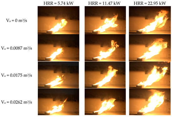

Figure 9.
Combustion flame shape of propane gas fire with different sidewall smoke exhaust rate.
Based on Equation (7) in theoretical analysis, it is concluded that this relationship can be expressed by the following functional formula:
where A and B are the correlation coefficients.
Based on Equation (9), the flame tilt angle was fitted as a function of the sidewall smoke exhaust rate and longitudinal ventilation velocity. The corresponding fitted coefficients are listed in Table 5. Figure 10 illustrates the relationship between the flame tilt angle and the sidewall exhaust rate under varying distances between the fire source and the sidewall exhaust outlet.

Table 5.
Fitted value of coefficients.
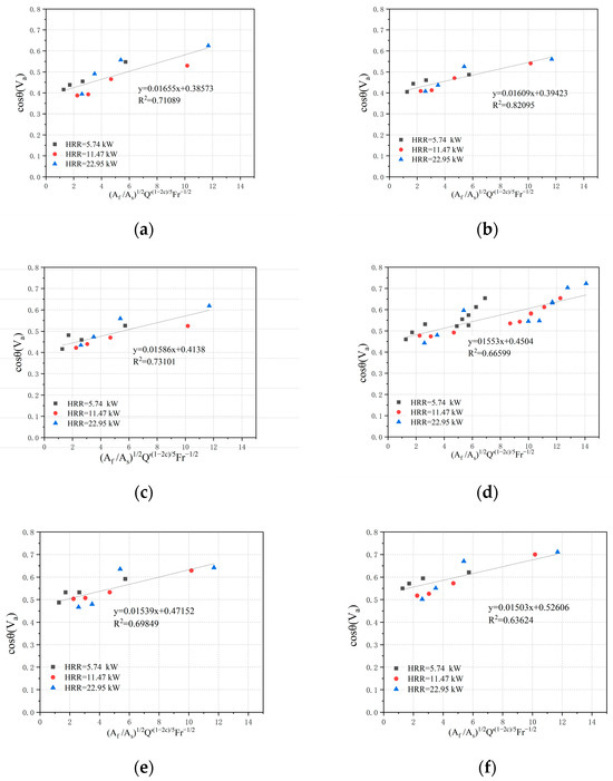
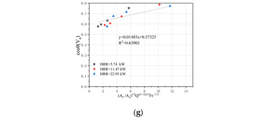
Figure 10.
Flame angle dimensionless function with varying sidewall smoke exhaust rates. (a) D = 0.12 m, (b) D = 0.24 m, (c) D = 0.36 m, (d) D = 0.48 m, (e) D = 0.6 m, (f) D = 0.72 m, (g) D = 0.84 m.
Figure 11 presents the different combinations of coefficients A and B derived from the non-dimensional analysis of the effective flame height Hef with respect to the distance D between the fire source and the sidewall exhaust outlet.
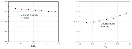
Figure 11.
The fitting coefficients A and B.
As shown in Figure 11, the fitting coefficient A decreases linearly with increasing D/Hef, while coefficient B exhibits a linear increase. Through linear regression analysis of the dimensionless distance D/Hef, the expressions for coefficients A and B are given as follows:
By substituting Equations (10) and (11) into Equation (9), a flame tilt angle prediction model incorporating the sidewall smoke exhaust rate under different fire source–sidewall distances are obtained as follows:
Figure 12 compares the predictive model developed in this study—considering a fire source located at the tunnel centerline under varying sidewall exhaust rates—with the model proposed by Kurioka et al. The results indicate that the predicted cos θ values from the present model are consistently higher than those derived from Kurioka’s model, corresponding to smaller flame tilt angles θ. This discrepancy arises because the sidewall exhaust reduces the effective longitudinal velocity near the fire source, which in turn exerts a reduced inertial force on the flame, leading to a decrease in the tilt angle.
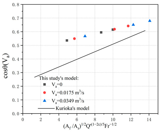
Figure 12.
Comparison of flame tilt angle prediction models.
Figure 13 depicts a comparison between experimental and calculated values derived from Equation (12). The predicted values obtained from Equation (12) show good agreement with the experimental measurements. These results confirm that Equation (12) can reliably predict the flame tilt angle under longitudinal ventilation conditions for varying distances between the fire source and the sidewall exhaust outlet.
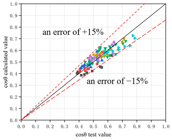
Figure 13.
Comparison between the experimental value and predicted value given by Equation (12).
5. Conclusions
This study investigated the effects of the distance between the sidewall smoke exhaust outlet and the heat source, as well as varying sidewall smoke exhaust rates, on the flame tilt angle in a tunnel under the combined influence of sidewall extraction and longitudinal ventilation. A series of reduced-scale tunnel experiments were conducted, and a new theoretical model was developed to predict the flame tilt angle. The main findings are summarized as follows:
- (1)
- At any transverse location within the tunnel, the flame tilt angle increases significantly with increasing longitudinal wind speed. In general, a greater distance between the fire source and the sidewall exhaust outlet correspond to a smaller flame tilt angle.
- (2)
- For a fixed fire source position and longitudinal wind speed, the flame tilt angle decreases progressively with increasing sidewall smoke exhaust rate. However, at sufficiently high wind speeds, the influence of sidewall extraction on flame behavior is diminished due to the dominance of the longitudinal airflow.
- (3)
- A new predictive model (Equation (12)) was proposed to estimate the flame tilt angle under the combined effects of longitudinal ventilation and sidewall smoke extraction, accounting for both the distance between the fire source and the sidewall outlet and the exhaust rate. Model predictions show good agreement with experimental results.
It should be noted that this study assumed equal densities for smoke and air in the theoretical analysis, which may introduce certain inaccuracies. In addition, as the experiments were conducted in a reduced-scale tunnel, further validation through full-scale tests is still required.
In conclusion, this work systematically investigated the effect of sidewall exhaust configuration on flame tilt behavior in an immersed tube tunnel. The results highlight the important roles of both the fire source position relative to the exhaust outlet and the smoke extraction rate in governing flame tilt characteristics. These findings offer valuable insights for improving flame inclination prediction and supporting fire safety design in immersed tube tunnels.
Author Contributions
Conceptualization, L.L.; Formal analysis, K.A.; Investigation, Z.W., X.Z. and Y.Z. (Yingdong Zhu); Methodology, K.A., Y.Z. (Yuanfu Zhou) and L.L.; Resources, L.L.; Validation, X.Z.; Writing—original draft, Z.W. and Y.Z. (Yingdong Zhu). All authors have read and agreed to the published version of the manuscript.
Funding
This work was supported by the Science and Technology Research Program of Chongqing Municipal Education Commission (KJZD-K202300713), the Chongqing Natural Science Fund Innovation and Development Joint fund (CSTB2024NSCQ-LZX0019).
Data Availability Statement
The original contributions presented in this study are included in the article. Further inquiries can be directed to the corresponding author.
Acknowledgments
Thanks to Chongqing Jiaotong University for providing the experimental platform and to the Chongqing Natural Science Foundation Innovation and Development Joint Fund Project for its financial support.
Conflicts of Interest
Zhenwei Wang and Ke An are employed by the company Chongqing Survey and Design Institute Co., LTD, Xueyong Zhou is employed by the company China Construction Tunnel Construction Co., LTD.
Nomenclature
| entity parameters | |
| model parameters | |
| the tunnel cross-sectional area (m2) | |
| the tunnel width (m) | |
| the tunnel height (m) | |
| the heat release rate (HRR) | |
| the dimensionless HRR | |
| the Froude number | |
| the longitudinal ventilation (m/s) | |
| the gravity acceleration (m/s2) | |
| the distance from the fire source surface to the tunnel ceiling (m) | |
| the ambient air temperature (K) | |
| the specific heat of air at constant pressure | |
| the density of air (kg/m3) | |
| the flame length (m) | |
| the smoke exhaust rate (m3/s) | |
| the actual wind speed in the tunnel (m/s) | |
| the density of smoke (kg/m3) | |
| the compensated volumetric flow rate(m3/h) | |
| the combustion efficiency | |
| the heat of combustion of propane (MJ/kg) | |
| the density of propane gas(kg/m3) | |
| constant |
References
- Haack, A.; Schreyer, J.; Meyeroltmanns, W.; Beyer, S. Brandschutz in Verkehrstunneln. 2000. Available online: https://trid.trb.org/View/956005 (accessed on 20 September 2025).
- Luo, Y.; Li, H.; Wei, T.; Ma, J. Study on the Coupled Smoke Characteristics and Evacuation of Underwater Immersed Tube in Tunnel Fire. Int. J. Front. Eng. Technol. 2023, 5, 30–36. [Google Scholar] [CrossRef]
- Kurioka, H.; Oka, Y.; Satoh, H.; Sugawa, O. Fire properties in near field of square fire source with longitudinal ventilation in tunnels. Fire Saf. J. 2003, 38, 319–340. [Google Scholar] [CrossRef]
- Zisis, T.; Vasilopoulos, K.; Sarris, I. Numerical simulation of a fire accident in a longitudinally ventilated railway tunnel and tenability analysis. Appl. Sci. 2022, 12, 5667. [Google Scholar] [CrossRef]
- Zhang, Y.; Chen, R.; Li, X.; Chen, L.; Xing, S.; Li, T. Study on the flame morphological characteristics of dual fire sources in tunnel under longitudinal ventilation. Fire Mater. 2022, 46, 919–926. [Google Scholar] [CrossRef]
- Tang, F.; He, Q.; Sun, X.; Jiang, L.; Hu, P.; Hu, L. Experimental study of carriage fire in a tunnel: Evolution of flame geometry characteristics under relative strong crosswinds. Proc. Combust. Inst. 2021, 38, 4963–4970. [Google Scholar] [CrossRef]
- Yu, Z.; Huang, X. Study of baffle height and wind velocity effect on the characteristics of pool fires in a wind tunnel. Appl. Sci. 2023, 13, 1920. [Google Scholar] [CrossRef]
- Ji, J.; Harada, K.; Ohmiya, Y.; Noaki, M. Tilt of flame from an item burning close to a wall. Fire Technol. 2018, 54, 1383–1404. [Google Scholar] [CrossRef]
- Kalech, B.; Bouterra, M.; ElCafsi, A. Study of the Thermal Buoyancy on the Smoke Flow in Tunnel Fires under the Coupled Effects of the Longitudinal Air-flow and the Tunnel Slope. J. Appl. Fluid Mech. 2024, 17, 1677–1686. [Google Scholar] [CrossRef]
- Xu, L.; Guo, H.; Ding, C.; Lu, Y.; Liu, J. Impacts of longitudinal air velocity and fuel flow rate on flame radiative fraction in tunnel. Sustain. Cities Soc. 2020, 61, 102336. [Google Scholar] [CrossRef]
- Fan, C.; Yang, L.; Luan, D.; Chen, T.; Jiao, A.; Ouyang, R.; Wang, J.; Chen, C. Experimental study on the effect of canyon cross wind on temperature distribution of buoyancy-induced smoke layer in tunnel fires. Transp. Saf. Environ. 2021, 3, tdab023. [Google Scholar] [CrossRef]
- Han, J.; Wang, F.; Wen, J.; Liu, F.; Ma, W.; Wang, Z.; Ma, Z. Investigation on the characteristics of fire burning and smoke spreading in longitudinal-ventilated tunnels with blockages. Tunn. Undergr. Space Technol. 2023, 131, 104790. [Google Scholar] [CrossRef]
- Haddad, R.K.; Zulkifli, R.; Maluk, C.; Harun, Z. Experimental investigation on the influences of different horizontal fire locations on smoke temperature stratification under tunnel ceiling. J. Appl. Fluid Mech. 2020, 13, 1289–1298. [Google Scholar] [CrossRef]
- Zhao, W.; Ouyang, R.; Ran, Q.; Chen, T.; Xu, Z.; Zou, M.; Fan, C. An experimental study on smoke back-layering and critical velocity in tunnel fires with canyon cross wind. J. Wind. Eng. Ind. Aerodyn. 2021, 209, 104477. [Google Scholar] [CrossRef]
- Sun, J.; Wang, J.; Fang, Z.; Tang, Z.; Merci, B. Study on the double effect of the tunnel slope on the fire induced smoke back-layering distance in naturally ventilated inclined tunnels. Tunn. Undergr. Space Technol. 2024, 143, 105478. [Google Scholar] [CrossRef]
- Chen, X.; Ding, Z.; Lu, S. Investigation of sidewall height effect on the burning rate and flame tilt characteristics of pool fire in cross wind. Fire Saf. J. 2021, 120, 103111. [Google Scholar] [CrossRef]
- Edalati-nejad, A.; Ghodrat, M.; Simeoni, A. Numerical investigation of the effect of sloped terrain on wind-driven surface fire and its impact on idealized structures. Fire 2021, 4, 94. [Google Scholar] [CrossRef]
- Lanchava, O.; Ilias, N.; Javakhishvili, G.; Radu, S.M.; Makharadze, L. Influence of current direction in longitudinal ventilated road tunnels on the backflow of combustion Produits, MATEC Web of Conferences. EDP Sci. 2022, 373, 00076. [Google Scholar]
- Wang, Y.; Huang, R. Experimental and numerical study of the trench fire spread rule over a sloped uniform fuel bed: Rate of fire spread, flame morphology, and heat flux. Fire 2023, 6, 469. [Google Scholar] [CrossRef]
- Levin, L.; Popov, M.; Semin, M.; Zhikharev, S. Experimental and Numerical Study of Air Flow Reversal Induced by Fire in an Inclined Mine Working. Appl. Sci. 2024, 14, 6840. [Google Scholar] [CrossRef]
- Liu, S.; Wang, L.; Yu, M.; Jiang, Y.-D. Optimization of smoke exhaust efficiency under a lateral central exhaust ventilation mode in an extra-wide immersed tunnel. J. Zhejiang Univ.-Sci. A 2021, 22, 396–406. [Google Scholar] [CrossRef]
- Xu, P.; Xing, R.J.; Jiang, S.P.; Li, L. Theoretical prediction model and full-scale experimental study of central smoke extraction with a uniform smoke rate in a tunnel fire. Tunn. Undergr. Space Technol. 2019, 86, 63–74. [Google Scholar] [CrossRef]
- Cetegen, B.M.; Ahmed, T.A. Experiments on the periodic instability of buoyant plumes and pool fires. Combust. Flame 1993, 93, 157–184. [Google Scholar] [CrossRef]
- Carvel, R.O.; Beard, A.N.; Jowitt, P.W.; Drysdale, D. The influence of tunnel geometry and ventilation on the heat release rate of a fire. Fire Technol. 2004, 40, 5–26. [Google Scholar] [CrossRef]
Disclaimer/Publisher’s Note: The statements, opinions and data contained in all publications are solely those of the individual author(s) and contributor(s) and not of MDPI and/or the editor(s). MDPI and/or the editor(s) disclaim responsibility for any injury to people or property resulting from any ideas, methods, instructions or products referred to in the content. |
© 2025 by the authors. Licensee MDPI, Basel, Switzerland. This article is an open access article distributed under the terms and conditions of the Creative Commons Attribution (CC BY) license (https://creativecommons.org/licenses/by/4.0/).