Article

Heat Exchanger Improvement of a Counter-Flow Dew Point Evaporative Cooler Through COMSOL Simulations

by
Mario García-González
1,*,
Guanggui Cheng
1,
Duc Thuan Bui
1 and
Josué Aarón López-Leyva
2,*
1
Engineering School, Jiangsu University, Zhenjiang 212013, China
2
Escuela de Ingeniería, CETyS Universidad, 22860 Ensenada, Baja California, Mexico
*
Authors to whom correspondence should be addressed.
Thermo 2024, 4(4), 475-489; https://doi.org/10.3390/thermo4040026
Submission received: 14 October 2024 / Revised: 1 November 2024 / Accepted: 9 November 2024 / Published: 12 November 2024
(This article belongs to the Special Issue Innovative Technologies to Optimize Building Energy Performance)

Abstract

:
Due to modern comfort demands and global warming, heating, ventilation, and air conditioning (HVAC) systems are widely used in many homes and buildings. However, HVAC based on the Vapor Compression System (VCS) is a major energy consumer, accounting for 20–50% of a building’s energy consumption and responsible for 29% of the world’s CO2 emissions. Dew-point evaporative coolers offer a sustainable alternative yet face challenges, e.g., dew point and wet bulb effectiveness. Given the above, dew point evaporative cooling systems may find a place to dethrone conventional air conditioning systems. This research aims to design a dew point evaporative cooler system with better performance in terms of dew point and wet bulb effectiveness. In terms of methodology, a heat exchanger as part of a counter-flow dew point cooling system was designed and analyzed using COMSOL simulations under different representative climatic, geometric, and dimensional conditions, taking into account turbulent flow. Next, our model was compared with other cooling systems. The results show that our model performs similarly to other cooling systems, with an error of around 6.89% in the output temperature at low relative humidity (0–21%). In comparison, our system is more sensitive to humidity in the climate, whereas heat pumps can operate in high humidity. The average dew point and wet bulb effectiveness were also higher than reported in the literature, at 91.38% and 147.84%, respectively. In addition, there are some potential limitations of the simulations in terms of the assumptions made about atmospheric conditions. For this reason, the results cannot be generalized but must be considered as a starting point for future research and technology development projects.

1. Introduction

Since the late 20th century, there has been an increase in global energy consumption and, as a result, an increase in CO2 emissions. In the last few decades alone, building energy demand in developed countries has risen to around 40% of total urban energy demand [1,2,3]. According to the International Energy Agency (IEA), in the last report of 2023, the operations of buildings account for 30% of global final energy consumption and 26% of global energy-related emissions (8% being direct emissions in buildings and 18% indirect emissions from the production of electricity and heat used in buildings) [4]. This is due to the growth of the world’s population and economy and the development of communication networks. This has drawn particular attention to the impact of global climate change on energy production and costs [5].
In a global context, according to other studies, energy used for domestic purposes accounts for about 7% of energy demand, yet it is responsible for 29% of CO2 emissions due to different systems, products, electrical loads, and energy sources (i.e., conventional and renewable energy resources). The latter is particularly true in countries with high ambient temperatures, as energy is linked to many daily activities [6]. Particularly in countries with extreme climates (i.e., extreme high and low temperatures), energy consumption increases because it is mainly used to keep the air temperature at a comfortable level. This is also a problem because the increase in energy consumption has been accompanied by a gradual increase in the price of electricity in countries such as Mexico or the USA [7,8]. In light of the above, according to the Office of Energy Efficiency and Renewable Energy (EERE), Heating, Ventilation, and Air Conditioning (HVAC) systems are the largest energy consumers in 21st-century society. In developed countries, more than 50% of the energy consumed in buildings is used for HVAC systems, which represent 20% of total energy consumption in these countries. However, this consumption is increasing in some developing countries, such as China, where inefficient HVAC systems consume up to 20% more than in other developed countries [3,9]. Currently, refrigerant-based Vapor Compression Systems (VCSs) are used for HVAC in most buildings and homes [10]. Refrigerant-based VCS appeared in the 19th century, and until today, this technology dominates the market, satisfying 90% of user demand. However, the extensive use of VCS is not without its disadvantages, as residential and commercial VCS consume 1304 TWh of primary energy, resulting in the emission of 1357 million tons of CO2 [11]. This indicates the high energy consumption of HVAC systems and the need to implement a lower energy consumption system to reduce CO2 emissions. An important technological option is the Evaporative Cooling System, an air conditioning system that uses the evaporation of water to cool the environment. This is an energy-efficient system, as it uses 20% less energy than the VCS AC system. Although this system consumes electricity, its use represents a reduction of almost 44% in CO2 emissions due to its energy-efficient design [5]. From a technological point of view, this technology has two standard configurations: direct and indirect evaporative cooling (DEC and IEC, respectively). Table 1 shows the characteristics and limitations of these configurations.
Although evaporative cooling technology has a high energy-saving potential, its effectiveness is limited concerning the performance of air conditioning [2]. However, this system has been modernized and redesigned to overcome its limitations in effectiveness by using novel heat exchangers, resulting in a system known as dew point evaporative cooling, or Maisotsenko (M-cycle). According to studies developed and tested in China and the UK using the Dew Point IEC system in different cities in both countries, such as London, Belfast, Beijing, and Xi’an, the energy consumption of a building of 50 m2 to 100 m2 is 0.3 to 3.1 kWh at temperatures between 20 °C and 40 °C, using an airflow of 570–1800 m3/h (depending on the inlet area of 0.2–0.4 m2) [2,12]. Considering the above, if all conventional air conditioning systems were replaced by M-cycle evaporative coolers, the theoretical reduction in CO2 emissions could reach 24% [6]. In terms of scalability, although the system is very suitable for low relative humidity locations (i.e., dry weather), it has the potential to be used in other weather regions but with less effectiveness. In fact, there are currently at least 20 million evaporative air conditioners (EAC) in the world, most of them in India and the USA [12,13,14]. Nevertheless, the evaporative cooling system could be successfully applied in very humid areas with the use of pre-dehumidification, which increases the performance and the regions where this system can be applied, according to a study in China, the UK, and Saudi Arabia [13]. As a result, it is expected that M-Cycle will gradually replace VCS AC systems and become the dominant system in the future.

2. Literature Review

To address the problem, the principal research was developed by Hsu et al. [15]. In general, wet-surface heat exchangers are analyzed to determine the configuration that optimizes the performance. The objective was to cool a stream of air to a temperature lower than the inlet wet-bulb temperature by the evaporation of water. In addition, three laboratory models and a commercial prototype were analyzed. Next, Riangvilaikul and Kumar [16] developed a dew point evaporative cooling system for sensible cooling of ventilation air for air-conditioning applications. They also conducted experiments to investigate the outlet air conditions and system effectiveness at different inlet air conditions (temperature, humidity, and velocity) covering dry, temperate, and humid climates. In particular, the weather conditions for the experiments were similar to a typical hot and humid summer day. Similarly, a novel building cooling system was proposed, named the DAV-cooling system, which integrates dew point evaporative cooling, air-carrying energy radiant air conditioning, and vacuum membrane-based dehumidification [17,18]. The literature review shows various experimental studies of dew point indirect evaporative coolers (DPIECs) with different technological innovations and their corresponding performances (mainly dew point and wet bulb effectiveness). For example, the use of different indirect evaporative cooler geometries and flow arrangements with a wet bulb effectiveness of 53% [19]. There are also reports of simulations and experiments of DPIEC in real applications where the dew point and wet bulb effectiveness were 85% and 115%, respectively [20]. Various methods have also been developed and implemented to optimize DPIEC systems, such as Single Objective Optimization (SOO) and Multi-Objective Optimization (MOO). Results have been achieved in terms of water and airflow patterns, annual water consumption, and improved operational and geometric characteristics [21,22,23]. Similarly, Wang et al. presented a parametric studio to evaluate the performance of their proposed system considering working ratio, air flow rate, and selecting as inlet air conditions the hottest month of the year in several cities in the world. The key findings of this study are that the cooling COP increases as the airflow increases and that the cooling performance improves at higher temperatures and lower relative humidity [24].

3. M-Cycle’s Theoretical Background

The characteristic of indirect cooling makes this system more attractive than direct cooling because indirect cooling can reach the dry bulb temperature without adding humidity to the room. However, indirect cooling has temperature limitations (low efficiency), which is an obstacle for deep application and dethrones the VCS system. A new system has been developed to overcome the disadvantages of conventional indirect cooling. The M-Cycle is an improvement on the indirect evaporative cooling design while retaining all of its advantages, such as cooling the air without adding extra humidity to the system (keeping humidity constant) (see Table 2). This system uses an indirect cooling thermodynamic process that extracts energy from the air by using the psychrometric renewable energy available from the latent heat of water evaporating in the air (it takes approximately 680 W or 2256 kJ to evaporate one kilogram of water at atmospheric pressure), causing the air temperature to drop to the ambient wet bulb temperature and close to the ambient dew point temperature [6]. The M-Cycle is available in two different configurations, cross-flow and counter-flow, the latter increasing efficiency and dew point effectiveness. The M-Cycle could be used for air conditioning as well as for cooling liquids and gases in various technological processes, but with energy savings of up to 80% [14]. Moreover, evaporative cooling is not limited to applications in building cooling, but there are many other agricultural and industrial applications [12,13,14]. It has also been found that the weather conditions make the M-Cycle suitable for many cities in the world where the characteristics of the M-Cycle, such as low electricity consumption, can be exploited.
Specifically, in the M-Cycle, two streams of air work together: the product stream (indoor air) and the working stream (outdoor air), but they are not in direct contact with each other. Initially, the product stream runs dry (not ducted) through parallel ducts, as this does not add or remove moisture from the stream (see Figure 1a). The working stream is driven through the dry channel (for the pre-cooling process) until it meets the holes or perforations for the wet channel (where the water is). When the working air encounters the wet surface of the channels, the water evaporates, and the working stream is cooled. This cooling absorbs heat from the workstream, which is directed to the heat exchange zone (HEX). The product air is cooled in this zone, and the workstream is exhausted, almost saturated, and cooler than the ambient air. Theoretically, the minimum possible temperature of the state is the dew point of the ambient air. In addition, Figure 1b shows the psychometric diagram of the M-Cycle process.

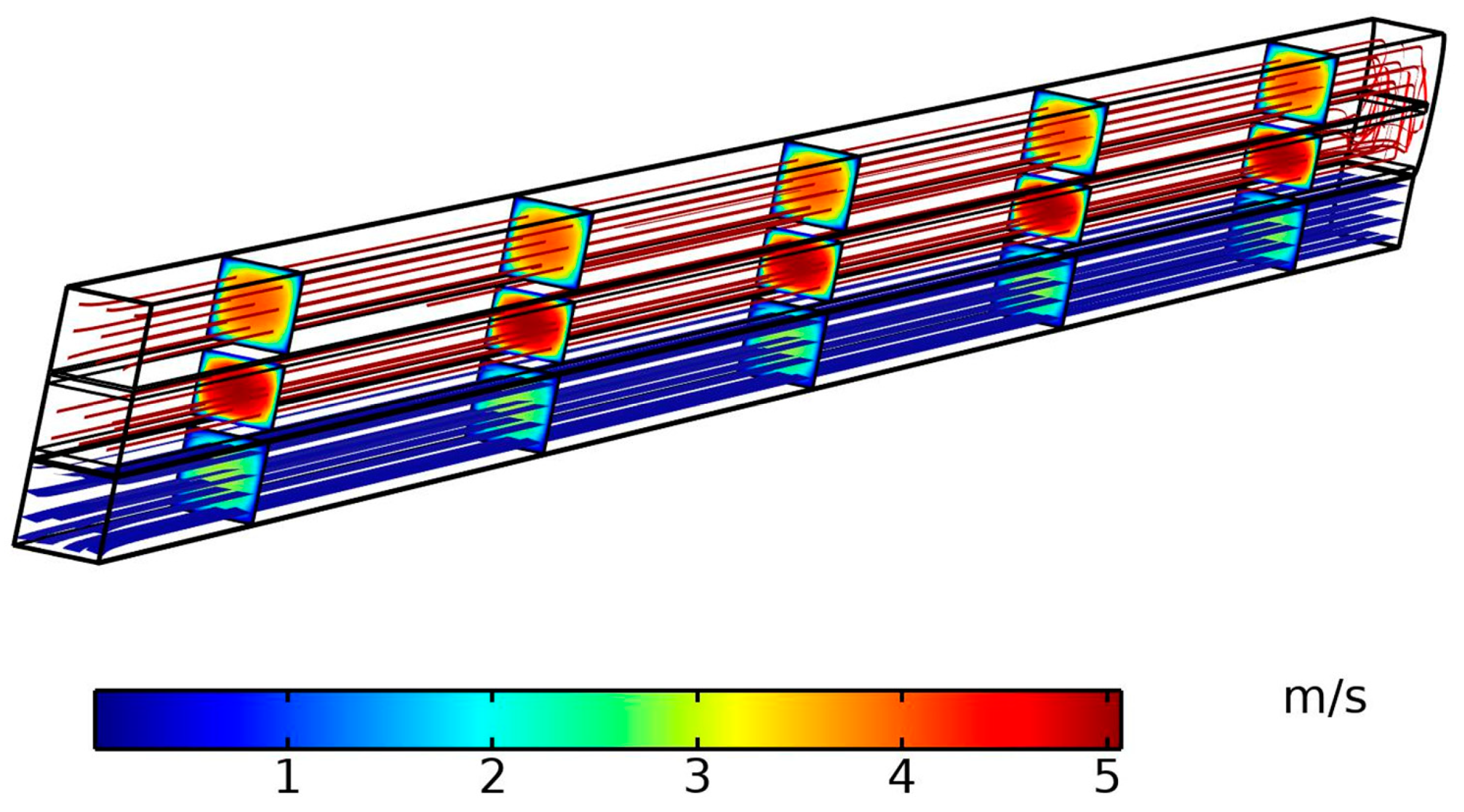
4. Modeling and Simulation

4.1. Mathematical Descripcion

To carry out the mathematical and simulation analysis of evaporative cooling systems, it is necessary to calculate the variables for wet (w) and dry (d) channels, heat transfer coefficient (hw,j and hd,j), and mass transfer (nw,j). They are calculated from the enthalpy added and removed (iw,j and id,j) and the mass flow (mw and md), taking into account the humidity distribution (ww,j) only for the wet channel. In Figure 2a,b, we can appreciate the direction of airflow (uspeed) through the area (A), which is calculated from the width (represented in the Y-axis, although the image-only height ( C Z ) is represented) multiplied by channel length. In addition, an arrow represents the flux of the energy in the system, going from left to right for the airflow and down to up for the heat. In the equations, j represents the direction of the airflow, with j as the air inlet and j + 1 representing the outlet. Due to there being two points of heat transfer, the Log Mean Temperature Difference (∆Twlm and ∆Tdlm) method was used. This method considers the temperature inside of the channel (Tw,jTd,j); in the case of wet channels, it is necessary to use the characteristics of the refrigerant (in this analysis, water was used): water density (a), constant water latent heat of vaporization (∆HVap), molar mass of water vapor ( m v ) and water temperature (Twater) are also considered [25]. Given the complexity involved, some assumptions are made:
-
Along the x-direction (∆x), the airflow is evenly distributed.
-
The airflow is turbulent.
-
Material properties (air, water, and duct material) are constant within each temperature/humidity range for each experiment.
-
Radiative heat flux from the surface to the environment is negligible.
-
Evaporation rates are constant throughout the experiment (each range).
Figure 2a shows the energy balance inside the dry channel before and after heat exchange, while the energy balance inside the wet channel before and after heat exchange is shown in Figure 2b [26].
It is to be noted that in the case of wet channels, the change in density must be taken into account as the liquid changes to saturated vapor. As a result, there are two different density values, so the Log Mean Difference method was used to calculate the density. It is important to note that when the refrigerant evaporates, it produces vapor of different densities, i.e., surface vapor (ρvs,j) and mean vapor (ρvm,j).
Given the above, the heat transfer rate can be calculated using Equations (1) and (2) and the heat transfer coefficients using Equations (3) and (4).
q d , j = h d , j A Δ T d l m = m d ˙ i d , j i d , j + 1
q w , j = h w , j A Δ T w l m , j = m w ˙ i w , j i w , j + 1 + Δ H v a p n w , j
h d , j = ρ a u d m C Z i d , j i d , j + 1 2 Δ x Δ T d l m , j
h w , j = ρ a u s p e e d C Z i w , j i w , j + 1 Δ H v a p w w , j w w , j + 1 2 Δ x Δ T d l m , j
In the context of the Log Mean Difference method, Equations (5) and (6) must be used for the calculated temperature and Equation (7) for the density.
Δ T d l m , j = T d , j T d , j + 1 ln T d , j / T d , j + 1
Δ T w l m , j = T w a t e r T w , j T w a t e r T w , j + 1 ln T w a t e r T w , j T w a t e r T w , j + 1
Δ ρ l m , j = ρ v s , j ρ v m , j ρ v s , j + 1 ρ v m , j + 1 ln ρ v s , j ρ v m , j ρ v s , j + 1 ρ v m , j + 1
In the case of mass calculation, the mass transfer is calculated using Equation (8) and the coefficient is calculated using Equation (9). All variables and symbols are described in the nomenclature table at the end of this document.
n w , j = m w ω w , j ω w , j + 1 = m m , j A Δ ρ l m , j
m m , j = ρ a u s p e e d C Z ω w , j ω w , j + 1 2 Δ x Δ ρ l m , j

4.2. Simulation

The model presented in the last subsection was designed using the CAD software Solid Works© (SolidWorks 2017) and numerically simulated using the COMSOL Multiphysics© software (COMSOL 5.6) with many physical interfaces, where the wide range of physical parameters required to simulate the dew point evaporator cooler can be calculated (see Table 3). This platform uses a Finite Element Method (FEM) to solve the equation. This method divides a large system (model) into smaller ones (finite elements) using a mesh that discretizes space and dimension. The resulting domain has a finite number of points. The FEM ultimately has a large number of algebraic equations divided into the number of boundaries of the domain. COMSOL Multiphysics© software has a selection for meshing with predefined parameters, called physics-controlled mesh. We selected fine mesh, which has predefined minimum and maximum element sizes of 0.0101 and 0.0804, respectively, growing at a maximum of 1.45 and curvature factor of 0.5. In addition, we have improved and modified some parameters (Size 1–3, Free Tetrahedral, Boundary Layers) to prevent problems in solving fluid flow, heat, and moisture transport.
In particular, the simulation was carried out in three stages according to the physical process: (1) airflow (see Figure 3), (2) evaporation (see Figure 4), and (3) heat transfer (producing the cooling effect). However, to save computing time and to prevent the diverging of solution in the simulation (i.e., not calculating a unique solution), the airflow through all the systems was simulated first, and then the evaporation of water and the heat transfer were simulated in turn. Then, based on the already simulated results of the airflow, we can achieve evaporative cooling without simulating the three processes at the same time.
At this stage, the airflow is modeled as a turbulent flow due to the shape and characteristics of the model; the Reynolds number is around 15,000, and the turbulence effect must be considered [27]. Moreover, we need to set the parameters that will be used as input for the next stages (heat transfer and moisture transport). We start with the assumption that the velocity and pressure field are independent of the air temperature and moisture content [27]. This assumption allows us to calculate the parameters in advance. Then, the main heat transfer occurs during evaporation (evaporation rate, K), where latent heat is released from the water surface, which cools down the environment and also cools down the water (for pre-cooling). The latent heat source (described by Equation (10)) is the product of evaporative flux and is considered by the latent heat of evaporation, where the vapor concentration (Cv) and the saturation concentration (Csat) are used.
q e v a p = Δ H v a p K C s a t C v m v
Before concluding this subsection, the settling time for considering a change to be imperceptible or negligible is reviewed. In other research, a steady state is considered to have been reached when the product air temperature changes less than 0.0005 °C in a given interval of 1 s [19]. However, we considered a negligible change to be 0.02 °C.

4.3. Model Validation

The model was simulated by varying the inlet temperature (for working and product air) from 25 °C to 40 °C and the relative humidity ratio from each temperature step to 20% to 80%. The simulation was a time-dependent study performed for 12 min (720 s), and a time interval of 10 s was chosen so that the variables remained constant or changed by less than ∆ = 0.02 °C. Therefore, to evaluate the error of the dynamic simulation and to validate the proposed model, the results of the air temperatures were compared with two models presented in two investigations.
Hsu et al. [15] carried out an experimental study (referred to in this document as the H-model) on a counter-flow closed-loop heat exchanger with a supply airflow of 34.2 °C dry bulb and 15.0 °C wet bulb. This model was selected because the configuration and length of the channel were similar to our proposed model. However, data such as channel size and ratio are not available, so a deeper explanation for the model difference cannot be supported (in our opinion, the differences between models lie in the width of the channel). Nevertheless, the aim of our model validation with the Hsu model was to show that both have similar behavior throughout the channel.
In this experiment, the supply air temperatures along the duct were measured at a steady state. Given the above, our model (referred to in this document as the P-model) was validated using their experimental data. Therefore, Table 4 shows the comparison between both models. Calculating the error compared to the results of Hsu et al.′s experiment, it is found that our proposed model predicts the dry stream temperature with an average accuracy (error) of −3.28%.
We also compared our model with the experimental evaporative cooling system of Riangvilaikul and Kumar (referred to in this document as the R-model) [16]. They carried out a series of experiments on a dew point evaporative cooler with four dry and five wet channels. This model was selected due to configuration and similarities in the design. In this research, the effects of inlet air temperature and humidity on steady-state performance were investigated individually, with each parameter being varied (one per experiment). According to the results and calculating the error, it is observed that the average discrepancy of the model is 17.08 ± 9.68% (where 9.68% is the coefficient of variation) between each temperature and each relative humidity (see Table 5) under different inlet temperatures or humidity. Even though the discrepancy is considerable, the performance of our model is comparable to that of Riangvilaikul’s model, being superior and inferior under certain circumstances. The difference between both models can be explained by the difference in the heat exchanger design and their respective parameters; the R-model has a channel length and width of 1200 mm and 80 mm, respectively, considerably larger than our model, having advantages in terms of heat exchanger capacity but limited in cooling speed. Another interesting difference is the air inlet; in the R-model, it enters perpendicular to the channel, and in the P-model, it enters parallel with the channel.
In Table 5, OT refers to the difference in output temperature. Consequently, when comparing the proposed system with the Hsu and Riangvilaikul models, our systems show an acceptable average discrepancy (error) of 6.89%. It is important to mention that although the heat exchanger has a direct effect on the error considering the design parameters, no data were provided at each stage, such as inlet speed, experiment time, and speed ratio.

5. Results and Discussion

5.1. Transient Response of Temperature and Humidity

The simulation was carried out using a counter-flow dew point evaporative cooling system model with controlled parameters. The evolution of the outlet temperature along the duct was studied. Table 6 shows the respective temperature responses of the product air, the working air, and the humidity response of the working air. In general, the temperature parameters are between 25 °C and 40 °C, and the humidity parameters are between 20% and 80%. We have two observations in the performance of the system; the first is that there is a sharp change in temperature at the beginning for all conditions.
This is due to the high energy required to change the water from a liquid to a gaseous state. The second phenomenon is that the resulting product air temperature is different for each relative humidity. This observation is also supported by Table 6, which shows the wet bulb and dew point efficiencies for an air inlet of 30 °C and relative humidities of 20% and 80%. The reference case is the same as that studied by Riangvilaikul, as we saw in the model validation section, and the comparison is made between the heat exchanger effectiveness and the relative humidity. This is because the higher the relative humidity, the lower the temperature that can be reduced by the evaporative cooling system, so the difference between the minimum temperature achievable and the temperature achieved by the heat exchanger is smaller. This effect is reversed when comparing wet bulb efficiency and relative humidity (see Table 6). In this case, the lower the relative humidity, the lower the temperature that can be achieved with an evaporative cooler, so the difference between the minimum dew point temperature that can be achieved and the temperature achieved by the heat exchanger is greater.
From the analysis presented, it can be concluded that dew point evaporative cooling is capable of supplying air at temperatures below the ambient wet bulb temperature and close to the dew point temperature. To design a system with high efficiency, we performed an analysis based on different combinations of relative humidity, temperature, channel size, channel material, speed, and ratio.

5.2. Dynamic Performance Under External Weather Conditions

As discussed in the previous section of this article, the evaporative cooling system has the potential to replace conventional air conditioning systems by offering competitive performance with savings in energy consumption. However, this system can be affected by the relative humidity of the environment, so we carried out a simulated experimental study of the dew point evaporative cooler under real environmental conditions. To do this, we selected 11 different representative cities around the world, representing a wide range of weather conditions (see Table 7). The experimental data were recorded considering the hottest month of the year, July, by selecting the day with the highest relative humidity [28].
It should be noted that the conditions chosen do not represent everyday urban conditions, but we believe it was necessary to evaluate the performance of the system under the worst conditions. The inlet air temperature ranged from ≈27 °C to ≈39 °C, and the relative humidity ranged from ≈4% to ≈76% [28]. Table 7 shows the comparison between the inlet temperature and the outlet temperature of our model. At the bottom, we can see cities such as Las Vegas, Madrid, and Mexicali. At the top, we can see cities such as Hermosillo, Beijing, and Xi’an. The performance (related to the outlet temperature of the P model) of the dew point evaporative cooling system is higher when the city is at the bottom of the table (i.e., for very low RH values) and, conversely, the performance is lower when the city is at the top of the table (i.e., for very high RH values). This means that the cities at the top represent the places where the performance of the dew point evaporative cooling system is not adequate. It can be observed that the inlet temperature does not have a proportional relationship with the outlet temperature. This can be seen by looking at cities such as Rome and Baltimore, which have the same inlet temperature but different outlet temperatures. From the above information, it can be deduced that other factors directly affect the system’s performance. For example, relative humidity is directly related to performance. As a result, fluctuations in inlet temperature also affect the system’s performance, but the most important aspect is the relative humidity. However, this does not mean that Evaporative Cooler (EC) cannot be used in cities such as Beijing or Cairo, as problems with high relative humidity can be overcome by the use of desiccant systems, especially in areas where humidity is only high at certain times of the year, as is the case in most of the cities shown at the top of the graph. This section of the study demonstrates the importance of understanding the effects of external weather on cooling system performance.

5.3. Analysis of the Physical Parameters of the Heat Exchanger

5.3.1. Channel Size

In the previous sections, the dew point EC system was analyzed, checking the efficiency and response under different input conditions to validate the system and its performance. In this section, the physical parameters of the heat exchanger are analyzed. A parametric analysis was carried out to design a highly efficient system with real-world applications. In the previous Figure 1a and Figure 2, a 2D scheme of a dew point evaporative cooling system was shown to represent the cooling process inside the heat exchanger. However, a real heat exchanger cannot be represented in two dimensions only, as the Y-axis (or width of the heat exchanger) is also a factor that affects evaporative cooling. Figure 5 shows a real heat exchanger in 3D. It consists of many channels arranged along the Y and Z axes, depending on the configuration and system objective, i.e., the heat exchanger can be composed of many Y channels (Y-ch or width) and Z channels (Z-ch or height). In particular, Figure 5a shows an isometric view of the heat exchanger, indicating the length and width (combined for the many individual channels). It also shows the matrix of individual channels into which the working and product air is introduced and exhausted. Figure 5b then shows a sectional view of the dry and wet channels. As an evaporative cooling system consists of many individual channels, the size of these channels is an important part of the heat exchanger and has been analyzed in this subsection.
Table 8 shows the comparison between the outlet temperature and the channel size (single channel), where the channel height (z-axis) and width (y-axis) were varied. It is important to note that we have compared the channel size with the outlet temperature to make the analysis easier to understand, but the variation of the channel parameters represents a direct variation of the volumetric flow in the channel, which is also directly related to the capacity of the system to cool a given space. It can be seen that the wider the channel, the higher the temperature reached (undesirable). This is explained by the fact that a wider duct contains more air, which means that more air is needed for cooling. However, the temperature reached is not the only aspect to be considered in a system with real applications. If the system is used to cool a room, the volume of air should also be considered.
Also, in Table 8, we find the square channel size with a length of 7 mm, which is far away from the group in the center. On the other hand, at the top, we find a 3 mm square channel. In the middle of the table is the rectangular channel. We can see that when the width of the channel is greater than the height, the temperature reached is lower. This is shown by the difference in outlet temperature between the 5 × 4 and 5 × 6 channels and the 4 × 5 and 6 × 5 channels. This is explained by the dynamics of the temperature flow, i.e., thermal conduction. In this system, the dry and wet ducts are placed together, and the dry duct is cooled by conduction when evaporative cooling occurs. This type of phenomenon requires the contact surface to move and transfer heat from one channel to another, and in the case of a channel that is higher, the contact surface is lower, causing a loss in performance. Considering the outlet temperature and the volume of air that the system can reach, the 5 × 5 duct is the best option (14.35 °C and 0.00005 m3/s) because the difference between the temperature reached in the other ducts (3 × 3, 4 × 4) is not negligible but not very large, while the volume flow is acceptable considering the larger ducts such as 7 × 7 and 6 × 6 but achieving a greater temperature.

5.3.2. Material of Heat Exchanger

Four types of materials were tested: plastics, metals, fibers, and mixtures, typically considering the material used for evaporative cooling and also the material proposed for the heat exchanger construction. It should be noted that in the case of material combinations, the order is always dry channel followed by wet channel. Table 9 shows the variation of the outlet temperature as a function of the material used.
In the table, we can see that the minimum temperature reached is that of a HEX made of aluminum, whereas a HEX made of polyester and fiber has poor performance, reaching temperatures far from the dew point. In the case of polyethylene, the performance is acceptable. The difference between the performance of a heat exchanger is explained by the thermal properties of the material. This property is the thermal conductivity characteristic of each material, and it is usually higher in metallic materials. However, it is a mistake to choose a material for the heat exchanger based on its thermal properties alone; the material must also have other important properties, such as resistance to oxidation, at least for the wet channel due to direct contact with water and steam. The cost of the material must also be considered, but this is beyond the scope of this paper.

6. Conclusions

In this paper, a counter-flow dew point evaporative cooling system has been proposed. In this analysis, it is deduced that the dew point evaporative cooling system can reduce the supply temperature below the wet bulb temperature (of the inlet air) and close to the dew point temperature. Using finite element analysis (simulations), parameters such as outlet air characteristics (temperature and relative humidity) and cooling efficiency are predicted based on inlet conditions. The results were compared with experiments carried out by other authors, and our results were positive, validating our proposed model. The counter-flow dew point evaporative cooling system proposed also performs better in hotter, drier climates. In locations such as Mexicali, Las Vegas, and Madrid, the cooler is suitable for stand-alone use, while in regions such as Hermosillo, Baltimore, Roma, and Beijing, it can be combined with air conditioners to improve ventilation and energy efficiency.
Nevertheless, due to the nature of this paper, since a real model has not been created and tested, the results have limitations in terms of reliability because although all the analyses have been simulated under the same circumstances, allowing results to be obtained considering a single variable, it has not been tested in real conditions (where we can find many uncontrollable conditions) to see the relationship between simulation and real models (although it is planned to do so in the future). The dew point evaporative cooling system has the potential to compete with the traditional air conditioning system. However, the market has to accept the new technology. At the same time, the development of this system has to take into account the needs and desires of its consumers, but also not be afraid to break with the status quo and offer something different that meets the expected performance but also follows the trend of low energy consumption. The simulations helped to design a heat exchanger with higher performance and also demonstrated the system’s operation under different climatic conditions, not only proving the viability of implementing this system but also providing improvement characteristics to be able to compete with traditional systems in terms of performance and cost.
In terms of future work, a high-fidelity prototype must be created, and then an industrial design must be developed. In addition, a major challenge is that the counter-flow dew point evaporative cooling system requires a constant supply of water and electricity, which can be complicated in certain parts of the world.

Author Contributions

Conceptualization, M.G.-G., G.C. and D.T.B.; methodology, M.G.-G., G.C. and D.T.B.; software, M.G.-G., G.C. and D.T.B.; validation, M.G.-G., G.C. and D.T.B.; formal analysis, M.G.-G., G.C. and D.T.B.; investigation, M.G.-G., G.C. and D.T.B.; resources, M.G.-G., G.C. and D.T.B.; data curation, M.G.-G., G.C. and D.T.B.; writing—original draft preparation, M.G.-G., G.C., D.T.B. and J.A.L.-L.; writing—review and editing, M.G.-G., G.C., D.T.B. and J.A.L.-L.; visualization, M.G.-G., G.C., D.T.B. and J.A.L.-L.; supervision, M.G.-G., G.C., D.T.B. and J.A.L.-L.; project administration, M.G.-G., G.C., D.T.B. and J.A.L.-L. All authors have read and agreed to the published version of the manuscript.

Funding

This research received no external funding.

Data Availability Statement

The data will be made available upon request from the author.

Conflicts of Interest

The authors declare no conflicts of interest.

Nomenclature

Symbols
xx-axis
yy-axis
zz-axis
Δxsection at x-axis
T d , j temperature at the dry channel at j instant, °C
i d , j enthalpy at the dry channel at j instant, J/kg
T d , j + 1 temperature at the dry channel at j + 1 instant, °C
i d , j + 1 enthalpy at the dry channel at j + 1 instant, J/kg
jinstant
q d , j heat transfer rate at the dry channel at j instant, W
T w , j temperature at the wet channel at j instant, °C
i w , j enthalpy at the wet channel at j instant, J/kg
T w , j + 1 temperature at the wet channel at j + 1 instant, °C
i w , j + 1 enthalpy at the wet channel at j + 1 instant, J/kg
ω w , j humidity at the wet channel at j instant (after evaporation), kg/kg
ω w , j + 1 humidity at the wet channel at j + 1 instant (air from dry channel), kg/kg
q w , j heat transfer rate at the wet channel at j instant, W
n w , j mass transfer rate at the wet channel at j instant, kg/s
h d , j heat transfer coefficient at the dry channel at j instant, W/m2K
h w , j heat transfer coefficient at the wet channel at j instant, W/m2K
m w mass flow at the wet channel, kg/s
m d mass flow at the dry channel, kg/s
uvelocity, m/s
Aarea, m2
TwlmLog Mean Temperature Difference at wet channel
TdlmLog Mean Temperature Difference at dry channel
awater density
HVapconstant water latent heat of vaporization
m v molar mass of water vapor
Twaterwater temperature, °C
ρvs,jsurface vapor
ρvm,jmean vapor
m d ˙ mass flow rate at dry channel, kg/s
m w ˙ mass flow rate at wet channel, kg/s
ρ a air density, kg/m3
u d m velocity in dry channel, m/s
u s p e e d velocity in wet channel, m/s
C Z channel height, m
Δ ρ l m , j Log mean density difference at j instant
Cvvapor concentration
Csatsaturation concentration
K evaporation rate
q e v a p latent heat source
m m , j mass transfer coefficient at j instant, m/s

References

  1. Lin, J.; Wang, R.Z.; Kumja, M.; Bui, T.D.; Chua, K.J. Multivariate scaling and dimensional analysis of the counter-flow dew point evaporative cooler. Energy Conv. Manag. 2017, 150, 172–187. [Google Scholar] [CrossRef]
  2. Amer, O.; Boukhanouf, R.; Ibrahim, H.G. A Review of Evaporative Cooling Technologies. Int. J. Environ. Sci. Dev. 2015, 6, 111–117. [Google Scholar] [CrossRef]
  3. Pistochini, T.; Modera, M. Water-use efficiency for alternative cooling technologies in arid climates. Energy Build. 2011, 43, 631–638. [Google Scholar] [CrossRef]
  4. International Energy Agency. Buildings. Available online: https://www.iea.org/energy-system/buildings (accessed on 2 October 2024).
  5. Duan, Z. Investigation of a Novel Dew Point Indirect Evaporative Air Conditioning System for Buildings. Ph.D. Thesis, University of Nottingham, Nottingham, UK, 2011. [Google Scholar]
  6. Tertipis, D.; Rogdakis, E. Maisotsenko cycle: Technology overview and energy-saving potential in cooling systems. Energy Emiss. Control. Technol. 2015, 3, 15–22. [Google Scholar] [CrossRef]
  7. Statista. U.S. Household Electricity Prices. 2023. Available online: https://www.statista.com/statistics/200199/residential-sector-electricity-prices-in-the-us-since-1975/ (accessed on 9 October 2024).
  8. Bernal, B.; Molero, J.C.; Perez De Gracia, F. Impact of fossil fuel prices on electricity prices in Mexico. J. Econ. Stud. 2019, 46, 356–371. [Google Scholar] [CrossRef]
  9. Energy. Office of Energy Efficiency & Renewable Energy. Heating, Ventilation, and Air Conditioning (HVAC). Available online: https://rpsc.energy.gov/tech-solutions/hvac (accessed on 2 October 2024).
  10. Mahmood, M.H.; Sultan, M.; Miyazaki, T.; Koyama, S.; Maisotsenko, V.S. Overview of the Maisotsenko cycle—A way towards dew point evaporative cooling. Renew. Sustain. Energy Rev. 2016, 66, 537–555. [Google Scholar] [CrossRef]
  11. Glanville, P.; Kozlov, A.; Maisotsenko, V. Dew Point Evaporative Cooling: Technology Review and Fundamentals. Ashrae Trans. 2011, 117, 111–118. [Google Scholar]
  12. Bom, J.; Foster, R.; Dijkstra, E.; Tummers, M. Evaporative Air-conditioning: Applications for Environmentally Friendly Cooling. World Bank Tech. Pap. 1999, 421, 1–69. [Google Scholar]
  13. Xu, P.; Ma, X.; Zhao, X.; Fancey, K. Experimental Investigation of a Super Performance Dew Point Air Cooler. Appl. Energy 2017, 203, 761–777. [Google Scholar] [CrossRef]
  14. Youssef, A.; Hamid, A. Energy saving potential of indirect evaporative cooling as fresh air pre-cooling in different climatic conditions in Saudi Arabia. In Proceedings of the 1st International Conference on Energy and Indoor Environment for Hot Climates, Doha, Qatar, 24–26 February 2014; pp. 256–263. [Google Scholar]
  15. Hsu, S.T.; Lavan, Z.; Worek, W.M. Optimization of wet-surface heat exchangers. Energy 1989, 14, 757–770. [Google Scholar] [CrossRef]
  16. Riangvilaikul, B.; Kumar, S. An experimental study of a novel dew point evaporative cooling system. Energy Build. 2010, 42, 637–644. [Google Scholar] [CrossRef]
  17. Chun, L.; Gong, G.; Peng, P.; Wan, Y.; Chua, K.J.; Fang, X.; Li, W. Research on thermodynamic performance of a novel building cooling system integrating dew point evaporative cooling, air-carrying energy radiant air conditioning and vacuum membrane-based dehumidification (DAV-cooling system). Energy Conv. Manag. 2021, 245, 114551. [Google Scholar] [CrossRef]
  18. Xiao, X.; Liu, J. A state-of-art review of dew point evaporative cooling technology and integrated applications. Renew. Sustain. Energy Rev. 2024, 191, 114142. [Google Scholar] [CrossRef]
  19. De Antonellis, S.; Cignatta, L.; Facchini, C.; Liberati, P. Effect of heat exchanger plates geometry on performance of an indirect evaporative cooling system. Appl. Therm. Eng. 2020, 173, 115200. [Google Scholar] [CrossRef]
  20. Badiei, A.; Akhlaghi, Y.; Zhaoa, X.; Li, J.; Yi, F.; Wang, Z. Can whole building energy models outperform numerical models, when forecasting performance of indirect evaporative cooling systems? Energy Convers. Manag. 2020, 213, 112886. [Google Scholar] [CrossRef]
  21. Liu, Y.; Akhlaghi, Y.G.; Zhao, X.; Li, J. Experimental and numerical investigation of a high-efficiency dew-point evaporative cooler. Energy Build. 2019, 197, 120–130. [Google Scholar] [CrossRef]
  22. Chen, Y.; Yang, H.; Luo, Y. Parameter sensitivity analysis and configuration optimization of indirect evaporative cooler (IEC) considering condensation. Appl. Energy 2017, 194, 440–453. [Google Scholar] [CrossRef]
  23. Golizadeh Akhlaghi, Y.; Aslansefat, K.; Zhao, X.; Sadati, S.; Badiei, A.; Xiao, X.; Shittu, S.; Fan, Y.; Ma, X. Hourly performance forecast of a dew point cooler using explainable Artificial Intelligence and evolutionary optimisations by 2050. Appl. Energy 2021, 281, 116062. [Google Scholar] [CrossRef]
  24. Wang, B.C.; Garcia, M.; Wei, C.D.; Cheng, G.G.; Pang, W.; Bui, T. Development and performance analysis of a compact counterflow dew-point cooler for tropics. Therm. Sci. Eng. 2023, 46, 102218. [Google Scholar] [CrossRef]
  25. Thermal Engineering. What is Logarithmic Mean Temperature Difference—LMTD—Definition. Available online: https://www.thermal-engineering.org/what-is-logarithmic-mean-temperature-difference-lmtd-definition/ (accessed on 9 October 2024).
  26. Lin, J.; Bui, D.T.; Wang, R.; Chua, K.J. On the fundamental heat and mass transfer analysis of the counter-flow dew point evaporative cooler. Appl. Energy 2018, 217, 126–142. [Google Scholar] [CrossRef]
  27. COMSOL. Tutorial Model of the Evaporative Cooling of Water. Available online: https://www.comsol.com/model/evaporative-cooling-of-water-6192 (accessed on 2 October 2024).
  28. Weather Spark. The Weather Year Round Anywhere on Earth—Weather Spark. Available online: https://weatherspark.com/ (accessed on 2 October 2023).
Figure 1. (a) Airflow in a counter-flow M-Cycle heat exchanger based on [5]; (b) psychometric chart of the M-Cycle process.
Thermo 04 00026 g001
Figure 2. (a) Thermodynamic variables across the dry channel. (b) Thermodynamic variables across the wet channel are based on [26].
Thermo 04 00026 g002
Figure 3. Airflow simulation using COMSOL.
Thermo 04 00026 g003
Figure 4. Evaporation simulation using COMSOL.
Thermo 04 00026 g004
Figure 5. (a) Three-dimensional isometric view of a real evaporative cooling system. (b) Sectional view of the dry and wet channels.
Thermo 04 00026 g005
Table 1. Evaporative cooler configuration characteristics.
ConfigurationCharacteristicsLimitations
Direct (DEC)Direct configurations add moisture to the inlet air (air supplied to rooms for cooling)- It is only suitable for use in dry and hot climates.
- Wet-bulb effectiveness of 70–80%
Indirect (IEC)It can reduce the air temperature
to dry bulb temperature.
This system avoids adding moisture to the air (inlet air humidity remains constant).
- Wet-bulb effectiveness of 40–80%.
- It is only suitable for use in dry and hot climates.
Table 2. M-Cycle main characteristics [2,6].
ConfigurationCharacteristics
M-Cycle- Indoor air and outdoor air work together, but without mixing.
- 50–80% dew-point effectiveness.
- Up to 80% of energy savings compared with conventional systems.
- Wet-bulb effectiveness of 90–130%.
- 10–30% higher effectiveness than conventional heat exchangers.
Table 3. Simulation conditions for the heat exchanger.
ParameterNominal ValueRange
Inlet Air Temperature25 °C25–40 °C
Air Humidity40% (8.02918 g/kg)20–80%
Air SpeedWet Channel—3 m/s1–4 m/s
Working Air RatioDry Channel—2 m/s1–4 m/s
Channel Length500 mmConstant
Channel (Height/Width)5 mm3–7 mm
Channel Thickness0.1 mmConstant
Water film Thickness0.2 mmConstant
Table 4. Outlet temperature (OT) in the proposed model (P model) and Hsu model (H model).
Channel Length(in)P Model
(°C)
H Model
(°C)
Error
(%)
034.434.40
422.258828.2−21.0681
819.16121.5−10.8791
1216.74616.23.3704
1614.488614.470.1285
2012.546111.212.0188
Table 5. Percentage error difference between the proposed model and the Riangvilaikul and Kumar model.
40 °C35 °C30 °C25 °C
RH (%)OT
P Model
OT
R Model
Error
(%)
OT
P Model
OT
R Model
Error
(%)
OT
P Model
OT
R Model
Error
(%)
OT
P Model
OT
R Model
Error
(%)
4023.1172619.36161415.4816.3511.811635
6030.1621.52925.77211921.320616.941912
8035.6127.52330.85271226.0626.5221.32622
Table 6. Heat exchanger efficiency.
RH (%)Dew Point
Effectiveness
Wet Bulb
Effectiveness
2078.16153.17
4090.34153.08
6097.10146.62
8099.91138.46
Table 7. Dew point evaporative cooling outlet temperature in different cities’ ambient conditions.
CityRH (%)Inlet Temp.
P Model
Outlet Temp.
P Model
Beijing, China76.531.0626.508
Xi’an, China7531.61526.521
Shenyang, China68.3327.94921.564
Cairo, Egypt6234.94723.08
Hermosillo, Mexico54.2539.94733.574
Baltimore, USA53.2530.94820.326
Chicago, USA4327.94914.891
Roma, Italy39.7530.50415.82
Mexicali, Mexico2135.24713.947
Las Vegas, USA439.9463.8361
Madrid, Spain1032.7252.7611
Table 8. Comparison table of channel size again outlet temperature (RH = 35% and inlet temperature = 30 °C). W = channel width, and H = channel height.
Channel Size
(W × H)
GeometryVolumetric Flow Rate, m3/sOutlet
Temperature, °C
3 × 3square0.00001813.99
4 × 4square0.00003214.10
5 × 5square0.0000514.35
6 × 6square0.00007215.97
7 × 7square0.00009819.04
5 × 4rectangular0.0000415.46
5 × 6rectangular0.0000616.91
4 × 5rectangular0.0000416.19
6 × 5rectangular0.0000617.6
Table 9. Comparison table of different materials again outlet temperature (RH = 35% and inlet temperature = 30 °C).
MaterialOutlet
Temperature
Aluminum14.353
Alum/Polythene15.2
Polyethylene17.545
Polyethylene/Fiber19.146
Fiber19.159
Polyester19.182
Disclaimer/Publisher’s Note: The statements, opinions and data contained in all publications are solely those of the individual author(s) and contributor(s) and not of MDPI and/or the editor(s). MDPI and/or the editor(s) disclaim responsibility for any injury to people or property resulting from any ideas, methods, instructions or products referred to in the content.

