Abstract
Tube bundle recuperators are generally designed to operate with smooth tubes. Structured tubes can be used to increase the efficiency of recuperators. Compared to smooth tubes, the surface for heat transfer is increased and thus heat transfer is enhanced. This effect is accompanied by an increased pressure loss, which must be kept as low as possible. Four tube geometries with different honeycomb structures are examined. The results are compared with the performance of a smooth tube. The investigations were carried out both numerically and experimentally at different off-gas and combustion air velocities. The experimental results show that the highest heat transfer is achieved with the concave 6 mm structured tube. The greatest pressure loss also occurs here. The validation of the numerical model has shown issues in resolving the turbulence.
1. Introduction
A large number of industrial furnaces in the metal, ceramics or chemical industry are operated with fossil fuels, oil or coal and, nowadays, hydrogen as a fossil-free alternative. For energy-efficient operation, the furnaces are equipped with heat recovery to preheat the combustion air. Central recuperators are often used for this purpose [1,2,3]. The principle of air preheating by central recuperators has been in use for decades (Figure 1). The use of tubes made of structured sheets in tube–bundle recuperators makes it possible to increase the heat-transferring area in a given installation space or to reduce the construction material requirement while maintaining the same heat-transfer area. Increasing the heat transfer coefficient leads to an increase in the transferred heat flux at the same initial temperature of the exchanging gases.
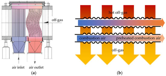
Figure 1.
(a) Schematic operating principle of a tube bundle recuperator [2] and its (b) gas exchange.
In the past, various techniques were used to manufacture tubes with structures for heat exchange. An increase in surface roughness leads to increased heat transfer, as Li et al [4] have shown. One way to increase surface roughness is to punch dimples in a sheet, which is then rolled to form a tube shape. Maithani and Kumar [5] investigated such a dimpled surface with regard to the correlation development of the Nusselt number and friction factor. Both key figures increase with the rise of the ratio of dimpled depth to print diameter until they reach 1, whereafter they decrease. Aroonrat and Wongwises [6], as well as Wang et al. [7], have confirmed this with their own investigations on dimpled tubes. The heat transfer coefficient and frictional pressure drop increase with the rise of dimpled depth. Cheraghi et al.’s [8] numerical study of the increase in heat transfer and pressure loss in deep-structured tubes corroborated the mentioned studies. Here, three main differences in the fluid flow of structured tubes in comparison to smooth tubes were found. The flow velocity increased at the bottom of the dimples, the vortexes were created after the dimples and there was an additional axial swirling in the flow’s direction. This led to more turbulent fluid flow with a higher heat transfer. Further numerical studies [9,10] have shown that an increase in heat transfer performance is associated with structuring. Further possibilities are the use of spirally structured [11] or corrugated [12] tubes. In both cases, the heat transfer coefficient of the structured surface increases significantly compared to a smooth surface. The heat flux and pressure loss characteristics are strongly dependent on the structuring.
The aim of the present study is to investigate alternative honeycomb-structured tubes, which are explicitly used in recuperators. Accordingly, a simplified recuperator model is created for the numerical investigations and a heatable flow channel is used for experimental validation.
2. Materials and Methods
As a reference for all investigations, a smooth, seamlessly welded, stainless-steel tube X5CrNi18-10 (Material number: 1.4301) was used. The investigated structured tubes resemble a honeycomb structure which is either pronounced inwardly (concave) or outwardly (convex). Two different honeycomb depths xd of each type were examined. The honeycomb depths are xd,1 = 3 mm and xd,2 = 6 mm. The structured tubes have been additively manufactured from X5CrNiMo17-12-2 (Material number: 1.4401) stainless steel. All tubes have an outer diameter of dt = 42.4 mm and a length of ltube = 1000 mm. A picture of the test tubes is shown in Figure 2.
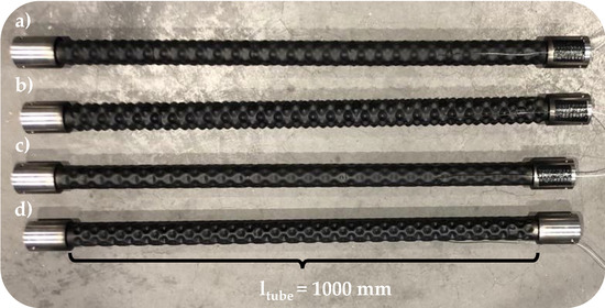
Figure 2.
Examined test tubes (a) convex 3 mm (b) convex 6 mm (c) concave 3 mm and (d) concave 6 mm with a tube length of ltube = 1000 mm.
As described in Section 1, the principle of a recuperator consists of transferring energy from the high temperature off-gas to the low temperature combustion air. It is not possible to carry out experiments in the technical centre using real off-gas, which is why all investigations were carried out with conventional air. For reasons of comparison, the numerical simulations were also carried out with conventional air. But, in order to distinguish more clearly between the flow of air inside the tube and the flow of air around it in the channel, the terms “combustion air” and “off-gas” will be used in the following, based on the functioning of a recuperator.
2.1. Numerical Modelling
A simplified model of a recuperator was constructed for numerical investigation. It consisted of a channel with length of lc = 1000 mm and a width wc = 500 mm, which corresponds to the tube length. The reduced tube length ltube = 500 mm was necessary due to computing time savings. A 3 × 3 tube bundle was located inside the channel. The tubes were arranged with a distance of 1.7 times the tube diameter. Outside the channel, there was also an inlet and outlet section connected to the test tubes. This ensured that the incoming flow was fully formed and that no backflow occured at the outlet. For the numerical investigation, the realizable k–ε model of Ansys Fluent 2022 R1 was used. The computational grid comprised about 6,000,000 cells. The numerical solution was terminated when the convergence criteria (residual < 10−6) were reached for every conservation equation.
In the model, two flows were considered separately from each other. On the one hand, there was the flow of combustion air within the tubes, which flowed into the tubes at room temperature Tair = 20 °C and whose velocity was set to vair = 1 m/s, 5 m/s and 20 m/s. The combustion air velocities assumed a Reynolds numbers of Re1m/s = 2668, Re5m/s = 13,342 and Re20m/s = 53,367 after the inlet section. Accordingly, all combustion air velocities were above the critical Reynolds number of Rec = 2300 with which the onset of turbulence corresponded. From Re = 10,000, completely turbulent conditions could be assumed [13]. The air flowed out of the tube via a pressure outlet. All pressure outlets had the boundary condition of a gauge pressure pgauge = 0 Pa. And, secondly, the flow of the off-gas around the test tubes was considered. Its temperature was Toff-gas = 500 °C and the off-gas velocity amounted to voff-gas = 0.5 m/s, 1 m/s and 5 m/s. The walls of the analyzed tubes were modelled applying shell conduction with a virtual layer thickness of xLayer = 2.5 mm. All other walls were assumed to be adiabatic.
2.2. Experiental Set-Up
The investigations of the test tubes took place in a flow channel, which could heat the air to a maximum of Toff-gas = 500 °C with an electric heating element. The air was circulated via a cross-flow fan. The experimental set-up is shown in Figure 3.
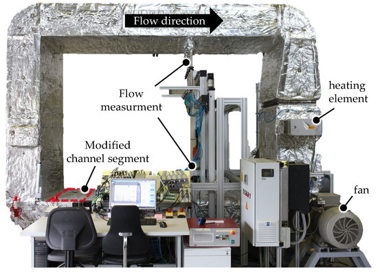
Figure 3.
Flow channel for investigating the heat transfer of various tubes.
In the channel, the flow velocity and its temperatures were precisely measured and monitored via integrated measuring technology. More information about the test bench can be found in Strämke [14]. A channel segment was converted for the thermal investigations of the structured tubes. A cross-section of this modified channel segment with the associated measurement technology is shown in Figure 4.
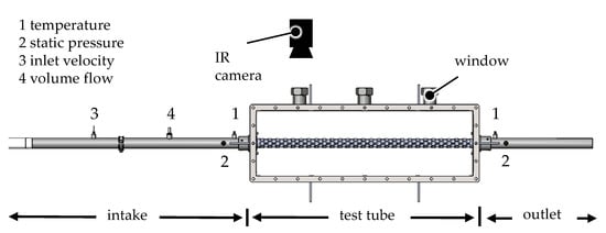
Figure 4.
Cross-section of the test bench with test tube and measurement technology.
At the beginning of the intake section of a single tube, a side channel compressor generates an air flow into the tube. Within the intake section, the volume flow , the flow velocity vair, the inlet pressure pair,in and the inlet temperature Tair,in are measured. In the test tube section, the tube wall temperature Twall is measured by a welded-on thermocouple. The built-in IR permeable windows at the top of the channel allow a contactless temperature measurement of the tube surface with an IR camera at two additional positions without thermocouples. This offers the advantage that the flow around the test tube is not affected. The measuring precision of the IR camera is ±1 K. In the subsequent outlet section, the outlet temperature Tair,out and the outlet pressure pout are measured. The pressure drop of the tubes is determined directly from the applied pressures in the inlet section and the outlet section. The measuring precision of the pressure transmitter is ±0.5%.
2.3. Determination of the Thermal Quantities
The thermal parameters such as the heat flux and heat transfer coefficient α cannot be measured directly like the pressure loss in order to compare the performance of the tubes. Therefore, as described in Section 2.2, further measured variables are recorded and the heat flux and the heat transfer coefficient α are subsequently calculated with corresponding assumptions.
The Biot number can be used to make a statement about whether a component can be assumed as thermally thin. For that, the Biot number must be significantly less than Bi << 0.1. In the present case of structured tubes, the assumption of a thermally thin tube means that the wall temperature on the outside of the tube is identical to the wall temperature on the inside of the tube at the same time. The dimensionless ratio of the Biot number is determined as:
To determine the Biot number, the heat transfer coefficient must be known. Since the heat transfer coefficient is currently unknown, it is replaced by the general equation of convective heat transfer:
The heat flux, which is also unknown, is calculated using the simplified steady-flow thermal energy equation:
The measured volume flow as well as the inlet and outlet temperatures of the air are included here. The measured volume flow is converted into the required mass flow via the temperature-dependent density of the air. The heat capacity of the air is taken from the literature. This way, the Biot number can be determined as:
To ensure that the estimation is valid for all investigations, the minimum temperature difference between the supplied combustion air and the off-gas is given, as well as the maximum heat flux that can be transferred. In this case, the characteristic length corresponds to the tube thickness xtube = 0.0025 m. In accordance with [15], the average thermal conductivity λ of stainless steel is 16–20 W/(m∙K) in a temperature range of 100–400 °C. The lowest thermal conductivity is assumed for the calculation. With these values, the Biot number is Bi = 0.013 << 0.1 and thus the tubes can be considered thermally thin. Thus, the heat transfer coefficient α can be calculated using the equation for convective heat transfer of flow-through tubes:
The calculated heat transfer coefficients are average heat transfer coefficients that apply to the entire tube surface. They are calculated from the total transferred heat flux of the tube surface, Equation (3). According to the equation of the error propagation:
the measurement uncertainties εy of the previously identified quantities are determined. F refers to the functions set up to calculate the measured value. The independent variables correspond to xi and their uncertainties are considered as εxi [16]. The uncertainties of the measured value acquisition of the temperatures are given within ±0.1% and those of the mass flow measurement within ±0.3%. The uncertainties of the calculated quantities of heat flux and heat transfer coefficient α of each test tube are shown in Figure 5.
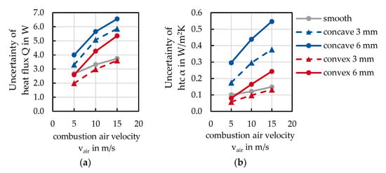
Figure 5.
Uncertainty of (a) the heat flux and (b) the heat transfer coefficient α.
The uncertainties shown in Figure 5 refer to the results in from Section 3.2. The uncertainty of the heat flux is dependent on the operating point and examined tube within ±2–6.5 W. This corresponds to 0.33% of the measured values in relation to the Section 3.
The uncertainty of the heat transfer coefficient also varies depending on the test tube and combustion air velocity. Here, the uncertainty is ±0.05–0.55 W/m2K, which, in relation to the measured heat transfer coefficients in Section 3.2, corresponds to 0.4% of the mean measured values.
3. Results and Discussion
3.1. Determination of the Tube Wall Temperature
To determine the tube wall temperature over the entire length, IR permeable windows were installed in the flow channel. At test point one, the tube wall temperature was measured using both a thermocouple and the IR camera. Thus, the emissivity, which is necessary for measuring the surface temperature by means of the IR camera, could be determined iteratively. The thermocouple was welded onto a bar between the honeycombs. A measuring field for determining the surface temperature by means of an IR camera was also placed on one bar. In this way, the influence of the surface curvature was minimised during temperature measurement.
In order to create a comparable tube surface and be able to estimate radiation restrictions, the tube was painted with a black thermographic paint. Due to the known emissivity of the first test point, the tube wall temperature could also be determined at test points two and three. Figure 6 illustrates the thermographic images of the convex 6 mm structured tube for the three test points at an off-gas temperature of Toff-gas = 200 °C.
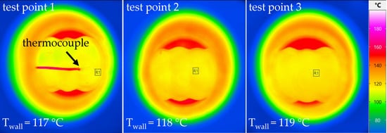
Figure 6.
Thermographic images of the convex 6 mm structured tube at three test points.
At test point one, the welded thermocouple can be seen very clearly. The tube wall temperature increases by 2 °C from test point one, Twall,1 = 117 °C to test point three Twall,3= 119 °C. With these IR glasses, tests were carried out up to 200 °C, above which there is a risk of oxidation of these windows. Figure 7 shows the tube wall temperatures of all test tubes for the three test points at an off-gas temperature of (a) Toff-gas = 100 °C and (b) Toff-gas = 200 °C at a combustion air velocity of vair = 15 m/s and an off-gas velocity of voff-gas = 5 m/s.
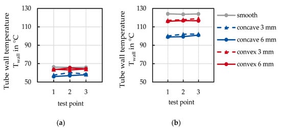
Figure 7.
Tube wall temperatures measured with the IR camera at three test points at (a) Toff-gas = 100 °C and (b) Toff-gas = 200 °C.
The wall temperatures at an off-gas temperature of Toff-gas = 100 °C were in the range of Twall = 55–65 °C for all tubes. It can be seen that the wall temperatures of the concave structure are slightly lower. No temperature differences could be detected between the individual test points.
When determining the wall temperature with an off-gas temperature of Toff-gas = 200 °C, the wall temperatures were higher than the measured wall temperatures at Toff-gas = 100 °C. The concave-structured tubes had the lowest wall temperatures with Twall ≈ 100 °C. The convex-structured tubes exhibited a wall temperature of about Twall ≈ 117 °C and are thus below the smooth tube, but clearly above the concave structure. The smooth tube shows a wall temperature of Twall = 124 °C. The difference in the measured wall temperature was ±2 °C between the individual test points.
Both measurements show no differences in wall temperature over the length of the tube. It was expected that the tube wall near the inlet would be colder when it was close to the outlet because heat transfer had already started. The measurements disproved the presumption and confirmed the assumption that the tube was a thermally thin component, see Section 2.3. Due to the clear results that the wall temperature was constant over the tube’s length, the wall temperature was measured only using the thermocouple when investigating at Toff-gas = 400 °C. This avoided the risk of the oxidation of the IR permeable windows.
3.2. Experimental Results
The set-up in which the test tubes were examined was outlined in detail in Section 2.2. In the results presented below, the flow through the off-gas was kept constant. The off-gas velocity was voff-gas = 15 m/s at an off-gas temperature Toff-gas = 400 °C. Figure 8 shows the measured correlation between the combustion air velocity vair and (a) the heat flux as well as (b) the internal heat transfer coefficient (htc) αinternal.
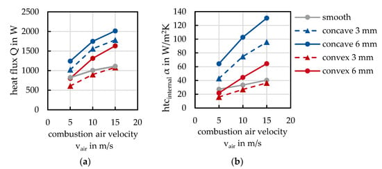
Figure 8.
Correlation of (a) the heat flux and (b) the internal heat transfer coefficient αinternal to the combustion air velocity vair.
Both the transferred heat flux and the heat transfer coefficient αinternal rose with increasing combustion air velocity vair. The slope of the increase differed with the structure of the tubes. The highest heat transfer was achieved with concave structuring. The concave 6 mm structured tube achieved the maximum heat flux = 2014 W and a maximum heat transfer coefficient αinternal = 131 W/m2K at a combustion air velocity of vair = 15 m/s. The less deeply structured 3 mm concave tube showed a similar increase, but at the same combustion air velocity it had a heat flux of = 1783 W and a heat transfer coefficient α = 96 W/m2K which were, respectively, less than the results for the 6 mm concave structured tube. Both concave structures clearly outperformed the smooth tube, which served as a reference.
A different behaviour can be seen with convex structuring. There, the convex 6 mm structure showed a comparable pattern to the concave structures, while the convex 3 mm structure did not reach the heat transfer of the reference. At a combustion air velocity of vair = 15 m/s, the convex 6 mm structure achieved a transferring heat flux of = 1632 W and a heat transfer coefficient α = 65 W/m2K. These values are clearly larger than the values achieved by the 3 mm convex structure of = 1082 W and α = 37 W/m2K.
From the results, it can be deduced that the increase in heat transfer is not solely due to the increased heat-transferring surface of the structured tubes, but is also significantly influenced by the flow characteristics inside the tube. The heat transfer area increases with increasing structure depth. In the case of the 3 mm convex structure, the heat transfer was not higher than that of the smooth tube, although the tube’s surface area increased. Regardless of the area-independent heat transfer coefficient having a steeper slope, the graph of heat flux flattens for all tubes. These two conspicuous characteristics indicate that the flow inside the tube also has an influence on heat transfer. Heat transfer is significantly influenced by the degree of turbulence.
Considering the observations from the simulations and by including further literature in Section 1, the results can be interpreted by backflows and recirculation within the structural patterns. The intensity of recirculation rises as the depth of the structure increases. Concave structures additionally reduce the mean flow area of the tubes, which leads to an increase in the mean flow velocity within the tube and also contributes to an increase in heat transfer. The increase in turbulence of convex structuring is based exclusively on backflows. There must be a sufficiently high flow velocity to pass through the honeycombs. According to the results, this is not the case for a honeycomb depth of xd,1 = 3 mm.
The structuring of the tubes always entails an increase in pressure loss, which is an important factor in the design of recuperators. The influence of the combustion air velocity vair on the pressure loss ∆p of all tubes is shown in Figure 9.
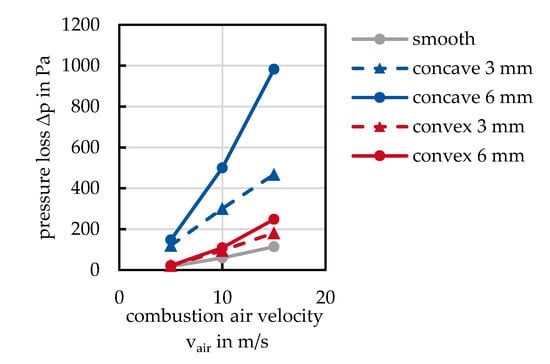
Figure 9.
Influence of the combustion air velocity vair on the pressure loss ∆p inside the tube.
The pressure loss of all structures exceeds that of the smooth tube. The pressure loss of the convex structuring is only slightly higher, while the pressure loss of the concave structuring is significantly higher. At a combustion air velocity of vair = 15 m/s, the highest pressure loss ∆p = 984 Pa is seen with the concave 6 mm structure. The increased pressure loss of the concave structure is due to the reduced flow area, which is not the case for the convex structure. For both types of structuring, the pressure loss increases with the depth of the structuring.
3.3. Numerical Results
In order to investigate the influence of both the off-gas and the combustion air flows on the heat transfer, a further numerical study was carried out. For this purpose, a uniform model was used for all test tubes, which is presented in Section 2.1. The respective influences are presented as main-effect diagrams [17]. A main-effect diagram is a standardized representation of effects, which is the difference between the mean values of individual quality characteristics. On the horizontal axis, the quality characteristics are listed. The vertical axis shows the value of a quality characteristic in the respective unit. The mean values are connected with a line, whereby the slope of this line indicates the effect.
In the present case, the off-gas velocity and combustion air velocity are plotted on the horizontal axes, each with three settings. The values are based on typical velocities in an industrial scale recuperator and present the minimum, the maximum and a frequently used operating point. The left side of the diagrams describes the effect on the combustion air velocity and the right side of the diagram describes the effect on the off-gas velocity voff-gas. Figure 10 presents the main-effect diagram of the heat flux related to the combustion air velocity and off-gas velocity.
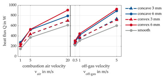
Figure 10.
Main-effect diagram of the transferred heat flux .
Both quality characteristics show a similar effect on the heat flow. With higher flow velocities, an increase in heat flux can be observed in both parts of the diagram. It can be seen that higher heat flows are achieved with increasing structural depth. All structured tubes transmit a heat flow that is greater than that of the smooth tube. Figure 11 presents the main-effect diagram for the heat transfer coefficient αinternal inside of the tube.
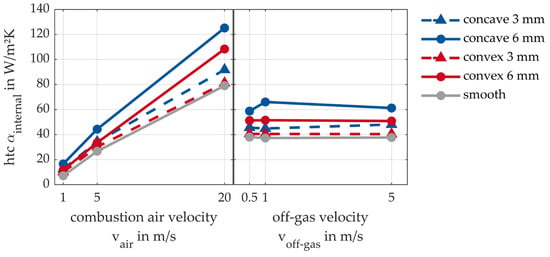
Figure 11.
Main-effect diagram of the internal heat transfer coefficient αinternal.
Only the flow of combustion air passing through the tubes influences the internal heat transfer coefficient, as it is separated spatially from the outer flow of the off-gas. With an increase in the depth of the structure, the internal heat transfer coefficient also increases. The highest internal heat transfer coefficient is achieved with the 6 mm concave structuring, followed by the 6 mm convex structuring. The convex 3 mm structure achieves comparable values to the smooth tube. Here, no significant improvement in heat transfer can be seen with the convex structuring. To assess which flow has a greater influence on heat transfer, the external heat transfer coefficient is considered in the following main-effect diagram (Figure 12).
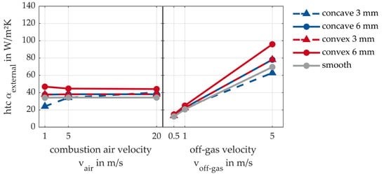
Figure 12.
Main-effect diagram of the external heat transfer coefficient αexternal.
For the main-effect diagram of the external heat transfer coefficient, the same behaviour can be observed as for the internal heat transfer coefficient: the external heat transfer coefficient is only influenced by off-gas velocity. Due to the spatial separation of the inner flow from the outside of the tube, no effect can be seen based on the combustion air velocity. The effect of the off-gas velocity is once again clearly evident. As the off-gas velocity increases, the external heat transfer coefficient increases. Here, the largest external heat transfers are achieved with 6 mm convex structuring. The external heat transfer coefficient of the 3 mm convex structuring and 6 mm concave structuring is on the same level.
A comparison between the values of the internal and external heat transfer coefficient shows that the internal heat transfer coefficient is higher. It can be deduced that the internal heat transfer coefficient takes on a superior role. However, it can also be seen that depending on whether the structuring is carried out inwards or outwards, the corresponding heat transfer coefficient is influenced more strongly. The main-effect diagram of the pressure loss in the tube is shown in Figure 13.
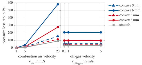
Figure 13.
Main-effect diagram of pressure loss ∆p inside the tube.
For completeness, the effect of combustion air velocity and off-gas velocity on pressure loss was also investigated. As expected, the pressure loss inside the tube is independent of the off-gas velocity flowing around the tube from the outside. The effect of the pressure loss outside the tube, i.e., in the recuperator itself, is not considered here. Between the combustion air velocities vair = 1 to 5 m/s, a moderate increase in pressure loss can be seen in all cases. After that, the slope varies up to vair = 20 m/s, depending on the structuring. The pressure loss of the 3 mm structured tubes is only slightly greater than that of the smooth tube, while the pressure loss is greatest in the concave 6 mm structured tube.
The numerical results, presented as main-effect diagrams, show that deeper structuring leads to increased heat transfer. Depending on the parameters considered, concave or convex structuring has advantages. With the statement of the main-effect diagrams of the area-dependent heat flux alone, no conclusion can be drawn about the main effect on heat transfer because both qualitive characteristics indicate a strong effect with comparable values. Looking at the main-effect diagrams of the area-independent internal and external heat transfer coefficients, it can be stated that the internal heat transfer coefficient takes on higher values than the external one. Accordingly, the higher heat transfer is present here, whereby the outer heat transfer is the limiting factor. Because the values are lower, the choice of off-gas velocity is important. Therefore, both flows are of equal importance.
3.4. Validations for the Chosen Model
The results of the simulation, Section 3.3, were validated on the basis of the measured results from Section 3.2. Due to the slight deviations between numerical and experimental results caused by the different tube lengths and off-gas temperatures, the corresponding results of the same condition were normalized to the smooth tube. That way, the influence of the structuring on the heat transfer and the pressure loss could still be compared and the numerical model could still be evaluated. The numerical model was validated for the parameters (a) pressure loss ∆p, (b) internal heat transfer coefficient αinternal and (c) heat flux (Figure 14).
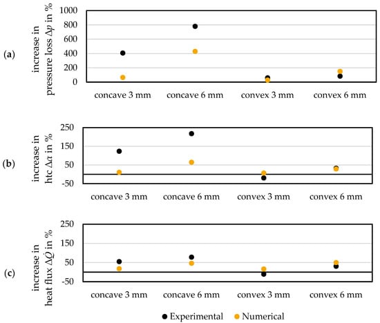
Figure 14.
Comparison of the experimental and numerical increases of the test tubes compared to the smooth tube in terms of (a) pressure loss ∆p, (b) heat transfer coefficient αinternal, and (c) heat flux .
Fundamentally, significant differences can be seen between the numerical model and the experimental results. In the modelling of the concave structures, the numerical model achieved worse results than the measurement. The numerical model had smaller deviations in modelling the convex structures, but predicted lower values than the measured results.
The comparison of the results from the concave-structured tubes leads to the assumption that the numerical model underestimates the turbulence. This results in a lower heat transfer and a lower pressure loss than the measurement showed. The situation is different when modelling the convex structures. There, the turbulence tends to be overestimated, resulting in an excessively high heat transfer and pressure loss.
These findings lead to the conclusion that it is not useful to investigate different tube structures with a model if quantitative values of heat transfer are required. The mesh resolution in the structures does not seem to be high enough to represent the turbulence sufficiently, although the numerical model shows good convergence properties. At this point, it is advisable to adapt the mesh to structure depth in order to enable a better resolution of the vortex structures, as well as to adapt the numerical model specifically to the given structure.
The aim of the investigation was to make qualitative statements in order to compare tube structures in particular. For this reason, a general numerical model was created, which also had identical mesh properties in which numerical influences on the results were avoided. Tendencies for the performance of structured tubes can be made comparatively for this application. For a deeper understanding of the inner and outer flow structures within the tubes, further numerical simulations would be required. A shortening of the tube length is proposed here in order to obtain a still-tolerable computation time at a higher grid resolution.
4. Conclusions
Recuperators can reduce the energy consumption of process routes in industrial plants. Their principle of operation is based on using the process’s off-gas and transferring its heat to the combustion air. This study of heat transfer from honeycomb-structured tubes is intended to increase the heat transfer between these two fluids. This can save further energy or reduce the amount of material used in recuperator tubes. For this purpose, four honeycomb tubes, two convex and two concave structured, were investigated both experimentally and numerically to compare their performance with that of the smooth tube. A simplified numerical model of a recuperator and an experimental set-up were established for the investigations.
The measured results show that only the concave structuring achieves a significant increase in heat transfer compared to the smooth tube. Thus, the concave structuring is an alternative to the smooth tube in increasing the heat transfer of the recuperators. However, it should be noted that pressure loss increases with greater concave structure depth. The convex 3 mm structured tube achieved no thermal advantage over the smooth tube, while the convex 6 mm structure had little advantage at higher combustion air velocities. However, the low thermal advantages do not justify a more costly production of convex-structured tubes compared to smooth tubes.
A further numerical study was used to give an assessment of which flow had the greater influence on heat transfer. The results were presented in the form of main-effect diagrams and showed that the internal heat transfer coefficient took on higher values than the external heat transfer coefficient. Thus, the bottleneck was on the outer tube surface. Therefore, both flow velocities had a high influence on heat transfer and must be selected in mutual dependence. The numerical study was validated with the measured data, which revealed significant differences in the individual values. The results of concave structuring were underestimated and those of convex structuring were overestimated. This leads to the conclusion that the numerical results should not be considered quantitatively and that a general model is only suitable for qualitative considerations.
The numerical modelling and the experimental results both show the distinct trend that with increasing combustion air velocity, heat transfer is increased, but also pressure loss rises. Further, an increased structure depth also leads to an enhanced heat transfer and an associated increase in pressure loss. The findings of [6] can be confirmed with respect to the increased heat transfer at a greater structure depth. The pressure loss is moderate in convex-structured tubes and is strongly noticeable in concave-structured tubes. The amount of heat transfer also differs with varying structural characteristics. While concave structuring brings significant heat transfer advantages, this does not occur with convex structuring. This behaviour corresponds with the results of [11,12] and confirms the strong dependence of heat transfer on the structuring.
Author Contributions
Conceptualization, E.T. and D.B.; methodology, E.T.; validation, E.T.; investigation, E.T.; writing—original draft preparation, E.T.; writing—review and editing, D.B. and H.P.; supervision, H.P.; project administration, E.T. and D.B.; funding acquisition, D.B. and H.P. All authors have read and agreed to the published version of the manuscript.
Funding
This research project is supported by the Federal Ministry of Economics and Climate Protection within the Central Innovation Program for small and medium enterprises on the basis of a decision by the German Bundestag under the AiF project no. KK5123801RH0.
Conflicts of Interest
The authors declare no conflict of interest.
Nomenclature
The following abbreviations are used in this manuscript:
| α, htc | Heat transfer coefficient | W/m2K |
| A | Tube surface | mm2 |
| Bi | Biot number | - |
| cp | Heat capacity | J/kgK |
| dt | Tube diameter | mm |
| εy | Measurement uncertainty | - |
| εxi | Uncertainty independent variable | - |
| F | Function | - |
| IR | Infrared | - |
| lc | Channel length | mm |
| ltube | Tube length | Mm |
| Thermal conductivity | W/mK | |
| Mass flow rate | kg/s | |
| p | Pressure | Pa |
| ∆p | Pressure loss | Pa |
| Heat flux | W | |
| Re | Reynolds number | - |
| Tair | Temperature combustion air | °C |
| Toff-gas | Temperature off-gas | °C |
| Twall | Temperature tube surface | °C |
| vai | Velocity combustion air | m/s |
| voff-gas | Velocity off-gas | m/s |
| wc | Channel width | mm |
| xd | Honeycomb depth | mm |
| xi | Independent variables | - |
| xLayer | Virtual layer thickness | mm |
References
- Pfeifer, H.; Beneke, F.; Nacke, B.; Langer, M. Plants for reheating semi-finished products prior to rolling. In Handbook of Thermoprocessing Technologies; Vulkan-Verlag: Essen, Germany, 2015. [Google Scholar]
- Pfeifer, H.; Beneke, F.; Nacke, B.; Bischoff, C. Central recuperators. In Handbook of Thermoprocessing Technologies; Vulkan-Verlag: Essen, Germany, 2015. [Google Scholar]
- Specht, E.; Becker, F. Öfen für geformtes Gut: Taschenbuch für den Maschinenbau. In Dubbel; Springer Vieweg: Berlin/Heidelberg, Germany, 2018; pp. 725–743. [Google Scholar] [CrossRef]
- Li, X.; Meng, J.; Li, Z. Roughness enhanced mechanism for turbulent convective heat transfer. Int. J. Heat Mass Transf. 2011, 54, 1775–1781. [Google Scholar] [CrossRef]
- Maithani, R.; Kumar, A. Correlations development for Nusselt number and friction factor in a dimpled surface heat exchanger tube. Exp. Heat Transf. 2020, 33, 101–122. [Google Scholar] [CrossRef]
- Aroonrat, K.; Wongwises, S. Experimental investigation of condensation heat transfer and pressure drop of R-134a flowing inside dimpled tubes with different dimpled depths. Int. J. Heat Mass Transf. 2019, 128, 783–793. [Google Scholar] [CrossRef]
- Wang, Y.; He, Y.-L.; Li, R.; Lei, Y.-G. Heat Transfer and Friction Characteristics for Turbulent Flow of Dimpled Tubes. Chem. Eng. Technol. 2009, 32, 956–963. [Google Scholar] [CrossRef]
- Cheraghi, M.H.; Ameri, M.; Shahabadi, M. Numerical study on the heat transfer enhancement and pressure drop inside deep dimpled tubes. Int. J. Heat Mass Transf. 2020, 147, 118845. [Google Scholar] [CrossRef]
- Han, H.-Z.; Li, B.-X.; Yu, B.-Y.; He, Y.-R.; Li, F.-C. Numerical study of flow and heat transfer characteristics in outward convex corrugated tubes. Int. J. Heat Mass Transf. 2012, 55, 7782–7802. [Google Scholar] [CrossRef]
- Kaood, A.; Abou-Deif, T.; Eltahan, H.; Yehia, M.A.; Khalil, E.E. Numerical investigation of heat transfer and friction characteristics for turbulent flow in various corrugated tubes. Proc. Inst. Mech. Eng. Part A J. Power Energy 2019, 233, 457–475. [Google Scholar] [CrossRef]
- Nelly, S.M.; Nieratschker, W.; Nadler, M.; Raab, D.; Delgado, A. Experimental and Numerical Investigation of the Pressure Drop and Heat Transfer Coefficient in Corrugated Tubes. Chem. Eng. Technol. 2015, 38, 2279–2290. [Google Scholar] [CrossRef]
- Sadighi Dizaji, H.; Jafarmadar, S.; Mobadersani, F. Experimental studies on heat transfer and pressure drop characteristics for new arrangements of corrugated tubes in a double pipe heat exchanger. Int. J. Therm. Sci. 2015, 96, 211–220. [Google Scholar] [CrossRef]
- Bergman, T.L.; Lavine, A.S.; Incropera, F.P.; Dewitt, D.P. Fundamentals of Heat and Mass Transfer; John Wiley & Sons: Hoboken, NJ, USA, 2011; ISBN 978-0470-50197-9. [Google Scholar]
- Straemke, S.; Pfeifer, H. Numerische und experimentelle Untersuchungen von Querstromventilatoren. Prozesswärme 2018, 1, 35–42. [Google Scholar]
- Spittel, M.; Spittel, T. 4.3 Thermal conductivity of steel. In Metal Forming Data of Ferrous Alloys—Deformation Behaviour; Martienssen, W., Warlimont, H., Eds.; Springer: Berlin/Heidelberg, Germany, 2009; pp. 89–97. ISBN 978-3-540-44758-0. [Google Scholar]
- Hedderich, J.; Sachs, L. Angewandte Statistik; Springer: Berlin/Heidelberg, Germany, 2018; ISBN 978-3-662-56656-5. [Google Scholar]
- Siebertz, K.; van Bebber, D.; Hochkirchen, T. Statistische Versuchsplanung; Springer: Berlin/Heidelberg, Germany, 2017; ISBN 978-3-662-55742-6. [Google Scholar]
Disclaimer/Publisher’s Note: The statements, opinions and data contained in all publications are solely those of the individual author(s) and contributor(s) and not of MDPI and/or the editor(s). MDPI and/or the editor(s) disclaim responsibility for any injury to people or property resulting from any ideas, methods, instructions or products referred to in the content. |
© 2023 by the authors. Licensee MDPI, Basel, Switzerland. This article is an open access article distributed under the terms and conditions of the Creative Commons Attribution (CC BY) license (https://creativecommons.org/licenses/by/4.0/).