1. Introduction
Natural convection is the flow caused by nonuniform density in a fluid. It is a fundamental process with applications from engineering to geophysics.
When a stationary, immersed object changes temperature, nearby fluid can change density as it warms or cools. Under the influence of gravity, density changes cause fluid to flow. The rates of fluid flow and heat transfer from the object grow until reaching a plateau. This investigation seeks to predict the overall steady-state heat transfer rate from an external, flat, isothermal surface inclined at any angle in a Newtonian fluid.
An “external” plate is one that fluid can flow around freely, especially horizontally. If enclosed, the enclosure must have dimensions much larger than the heated or cooled surface. Natural convection in an enclosure of size comparable to the heated or cooled surface can organize into cells of Rayleigh-Bénard convection, which is not treated here.
The characteristic length L is the length scale of a physical system. For many heat transfer processes, it is the volume-to-surface-area or area-to-perimeter ratio of the heated or cooled object. There are several characteristic length metrics used for natural convection, some of which are valid only for convex objects. This investigation focuses on flat plates with convex perimeters.
1.1. Flow Topologies
There are three topologies of convective flow from external, convex plates.
For a horizontal plate with a heated upper face, streamline photographs in Fujii and Imura [
1] show natural convection pulling fluid horizontally from above the plate’s perimeter into a rising central plume.
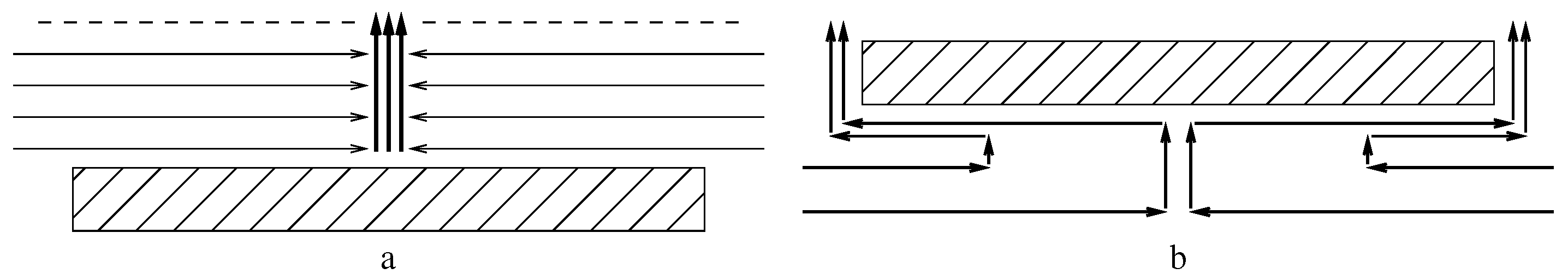
Figure 1a, below, is a diagram of this upward-facing convection. Horizontal flow is nearly absent at the elevation of the dashed line.
Kitamura, Mitsuishi, Suzuki, and Kimura [
2] show top-views of plumes from heated rectangular plates with aspect ratios between 1:1 and 8:1. The plates with high aspect ratios have a plume over the plate’s mid-line parallel to the longer sides, but not as long.
The streamline photograph of a vertical plate in Fujii and Imura [
1] shows fluid being pulled horizontally before rising into a plume along the vertical plate.
Modeled on a streamline photograph in Aihara, Yamada, and Endö [
3],
Figure 1b is a flow diagram for a horizontal plate with heated lower face. Unheated fluid below the plate flows horizontally inward. It rises a short distance, flows outward closely below the plate, and flows upward upon reaching the plate edge.
There is a symmetry in external natural convection; a cooled plate induces downward flow instead of upward flow. Flow from a cooled upper face is the mirror image of flow from a heated lower face. Flow from a cooled lower face is the mirror image of flow from a heated upper face.
Sublimation from an upper face is downward convection when the dissolved sublimate is denser than the fluid. The rest of this investigation assumes a heated plate.
An important aspect of all three flow topologies is that fluid is pulled horizontally before being heated by the plate. Pulling horizontally expends less energy than pulling vertically because the latter does work against the gravitational force. Inadequate horizontal clearance around a plate can obstruct flow and reduce convection and heat transfer.
1.2. Fluid Mechanics
In fluid mechanics, the convective heat transfer rate is represented by the average Nusselt number (). The Rayleigh number () is the impetus to flow due to temperature difference and gravity. A fluid’s Prandtl number () is its momentum diffusivity per thermal diffusivity ratio. These three “variable groups” are dimensionless (measurement units of the constituent variables cancel each other).
The characteristic length L scales ; is scaled by ; is independent of L.
Formulas for heat transfer can apply to mass transfer via analogous variable groups, such as Schmidt number (
) and
.
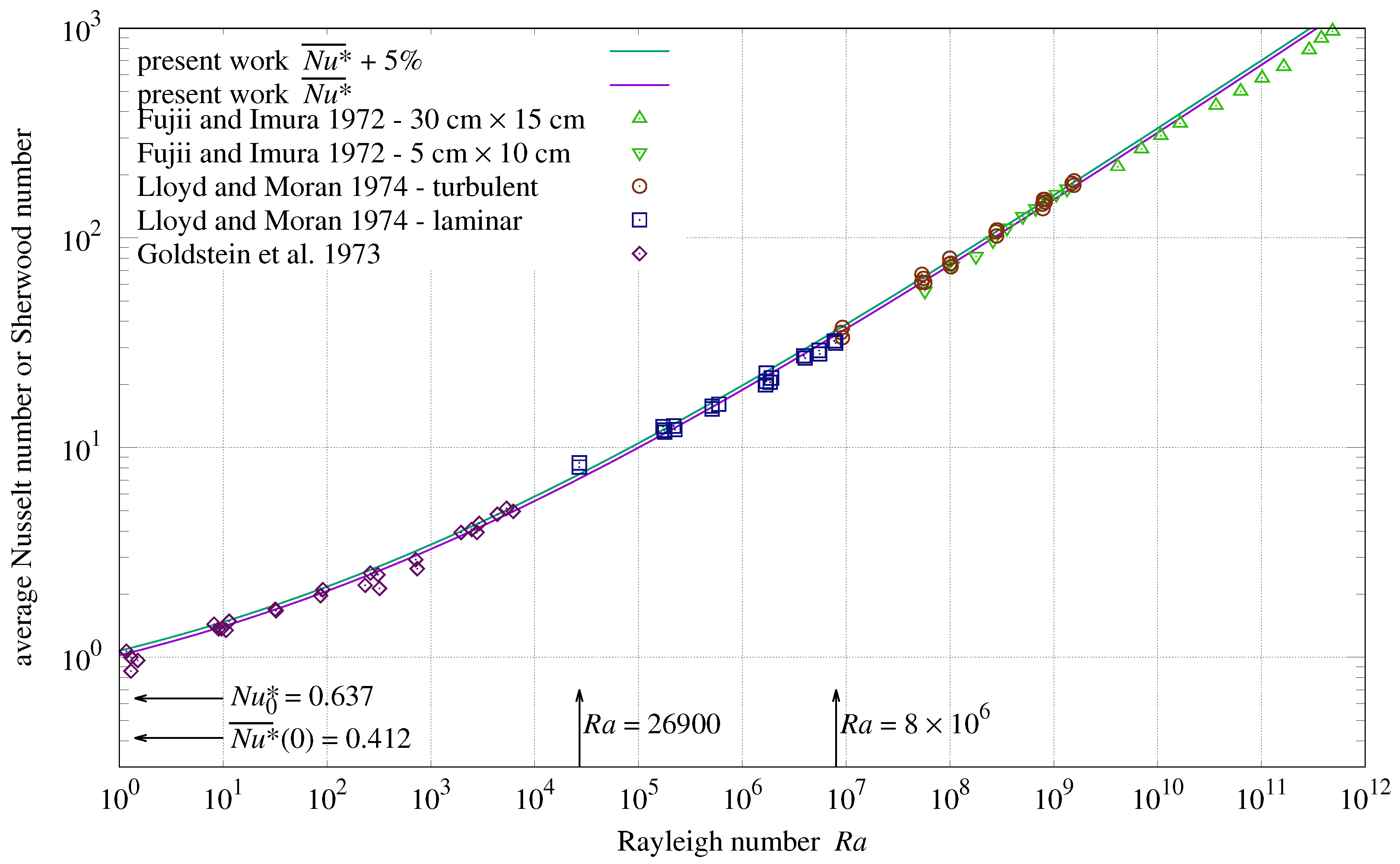
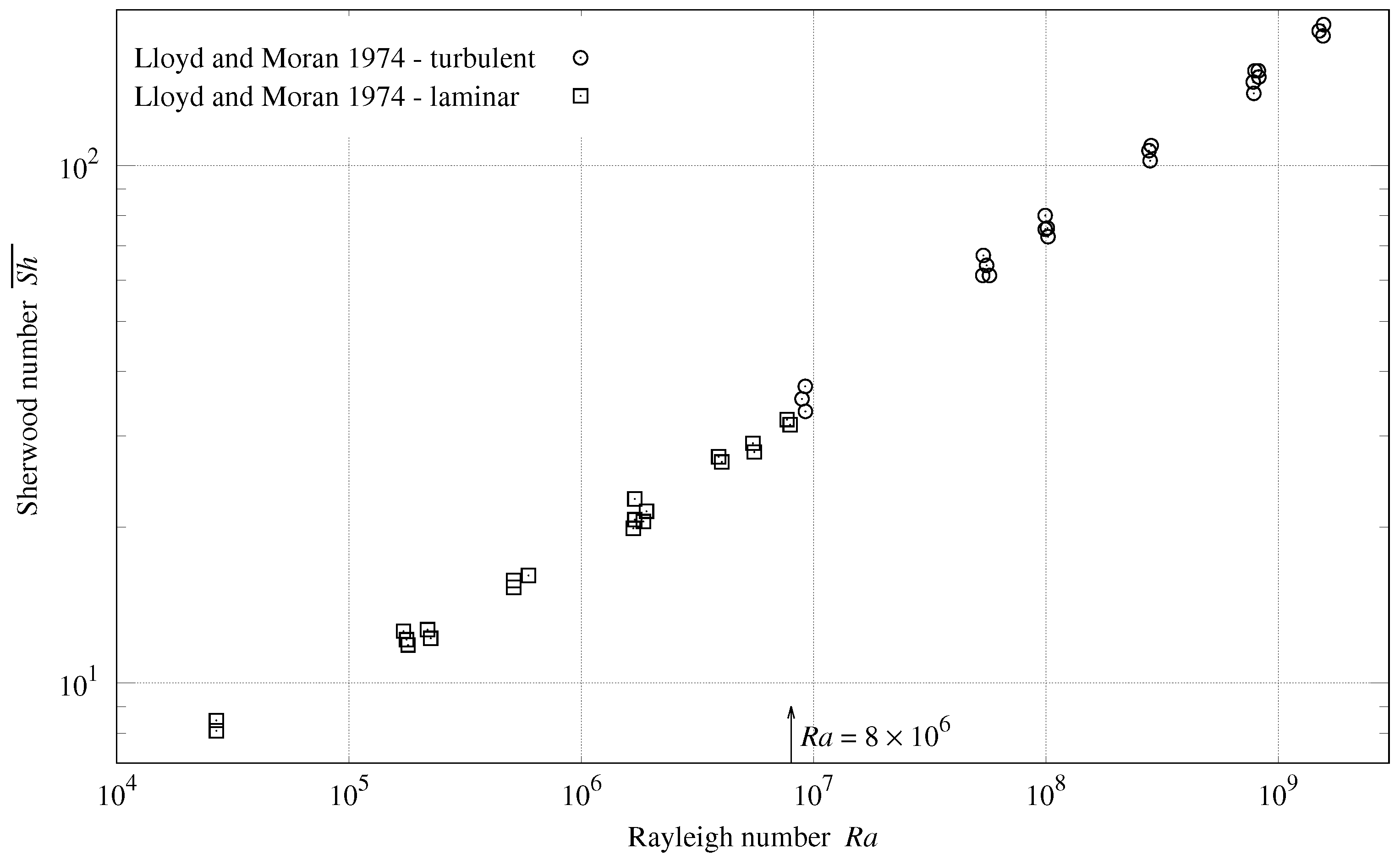
Figure 2 has Sherwood number (
) instead of
on its vertical axis.
1.3. Turbulence Versus Laminar Flow
Previous investigations [
1,
2,
4,
5] assumed that natural convection heat transfer formulas would differ substantially when the convection was turbulent versus laminar. For their upward-facing plate, Lloyd and Moran [
4] reported that the transition from laminar to turbulent flow occurred at
. The straight line segments they fitted to their data at greater and lesser
were disjoint at
. However, with their fit lines removed, if
represents a discontinuity, then it is one of several, and subsumed within the scatter of their measurements in
Figure 2.
About their measurements of vertical and downward tilted plates, Fujii and Imura [
1] wrote:
“Though the boundary layer was not always laminar near the trailing edge for large [] values, no influence of the flow regime on the data shown …is appreciable.”
Churchill and Chu [
5] conclude that one of its equations
“…based on the model of Churchill and Usagi [
6] provides a good representation for [sic] the mean heat transfer for free convection from an isothermal vertical plate over a complete range of Ra and Pr from 0 to ∞ even though it fails to indicate a discrete transition from laminar to turbulent flow.”
The lack of a significant transition between the rates of (mean) heat transfer in laminar and turbulent natural convection indicates that a more basic principle organizes natural convection.
1.4. Thermodynamics
The fundamental laws of thermodynamics make no distinction between laminar and turbulent flows. Considering a small object inside a very tall column of fluid as a closed system, natural convection is a heat engine that converts the temperature difference between the object and fluid into the flow of that fluid. The heated object is the heat source; fluid far above the object is the heat sink.
System-wide thermodynamic constraints cannot be enforced locally, requiring a radical departure from boundary-layer analysis (which is based on local flow solutions of the Navier–Stokes equations). This investigation solves algebraic equations in terms of average fluid velocity, heat conduction, and power flux.
1.5. Not Empirical
Empirical theories derive their coefficients from measurements, inheriting the uncertainties from those measurements. Theories developed from first principles derive their coefficients mathematically. For example, the Blasius model of laminar flow coefficient
is the solution of a differential equation (Lienhard and Lienhard [
7]). Another example is the heat conduction shape factor for one face of a disk, which is exactly twice its diameter. The present theory derives from first principles; it is not empirical. (The conduction shape factor
is used in
Section 8. It is derived exactly in
Section 16.) Each equation term is tied to an aspect of the plate geometry, orientation, and flow diagram.
This investigation tests its theory on prior works’ measurement data with as wide a range of
and
as possible. Few of the cited studies provided estimated measurement uncertainties. Root-mean-squared relative error (RMSRE), introduced in
Section 7.5, provides an objective, quantitative evaluation of each data set versus the theory.
1.6. Detail
Were this theory derived using the usual fluid-mechanics techniques, derivation detail would be unnecessary. However, this powerful new methodology is unlike those techniques. The first derivations provide more detail to enable readers to adapt the present methodology to other fluid mechanics problems.
2. Materials and Methods
There are robust measurements of natural convection heat and mass transfer in the peer-reviewed literature.
Table 1 lists the data-sets to be compared with the present theory. Within each face group, all
have been scaled to the same characteristic length metric. The “±” column is the estimated convection measurement uncertainty (scatter from Lloyd and Moran [
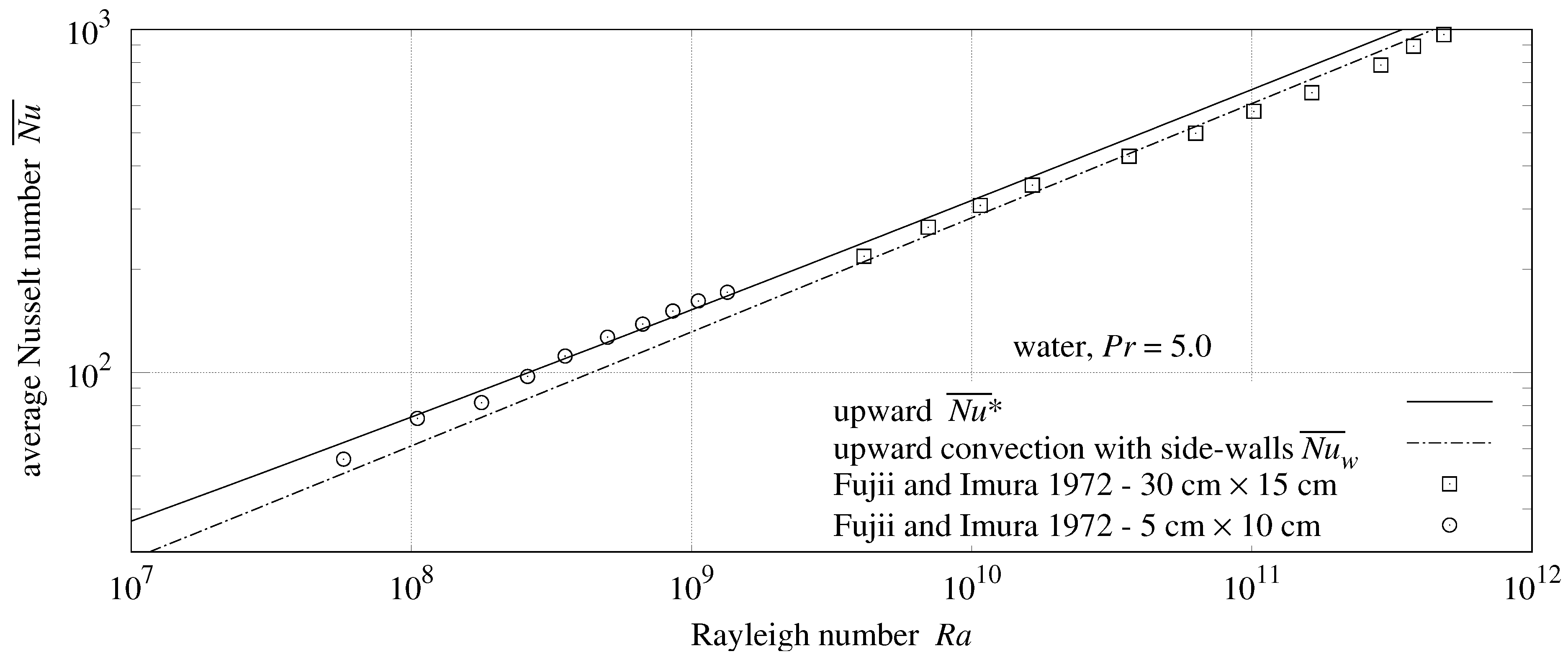
4]) reported in the cited source. Both plates from Fujii and Imura [
1] had side walls.
Measurements were copied from the text of Aihara et al. [
3], Faw and Dullforce [
10], and Goldstein and Lau [
11]. The remaining heat transfer measurements were captured from graphs in the cited works by measuring the distance from each point to its graph’s axes, then scaling to the graph’s units using the “Engauge” software. Measurements obscured by other points in the graph were excluded. (Excluding the obscured points eliminates clustered points, not outliers; thus, correlations with theory will tend to be weaker than if all the points had been included.)
These data files, which were used for generating the present work graphs and tables, are collected in
Supplementary Material.
3. Prior Work
3.1. Atmospheric Science
Rennó and Ingersoll [
12] relate the “convective available potential energy” (CAPE) of a planetary atmosphere to heat-engine efficiency. Atmospheric convection is analyzed as a four-phase cyclic heat engine. They introduce “total convective available potential energy” (TCAPE) in terms of the reversible heat-engine efficiency limit
. For dry air:
where
is the fluid’s specific heat (at constant pressure),
T is the absolute temperature of the ground (heat source), and
is the upper atmosphere (heat sink) absolute temperature.
, where is the heat-engine efficiency of natural convection. Rennó and Ingersoll assert that . Thus, .
The Goody [
13] cyclic heat-engine analysis splits atmospheric convection into four phases, three of them reversible, and accounts for their energy flows and entropy.
Table 2 shows the sink (
) and source (
T) temperatures, the efficiency limits from Goody (
), and
. In the first row,
matches
within
. In the second row,
is 30% larger than
. The third row changes
from 260 K to 250 K, causing
and
to match within 1%. If “260 K” was a misprint, then both studies agree that
.
3.2. Upward Natural Convection from a Horizontal Plate
For upward convection heat or mass transfer from a horizontal surface, prior works [
1,
2,
4,
8,
11] propose constant coefficients fitted to fractional powers of
, spanning various
ranges. The goal of this investigation being a comprehensive formula, the present theory will be compared with the measurements presented in these works, not with their piece-wise power-law approximations.
3.3. Natural Convection from a Vertical Plate
The natural convection heat transfer formula developed by Churchill and Chu [
5] for a vertical rectangular isothermal plate is:
3.4. Downward Natural Convection from a Horizontal Plate
Schulenberg [
14] derives a formula for convection below a level isothermal strip of width
. The Schulenberg [
14] heat transfer formula for an isothermal strip was:
1.156 is the only 4-digit coefficient in the paper’s isothermal plate correlations; the others have 3 significant digits.
Section 11 graphically demonstrates the discrepancy.
Proposed is a corrected formula and its equivalent, normalized so that
appears only in the denominator:
Schulenberg also gives a formula for downward convection from a level isothermal disk using its radius as the characteristic length. The expression on the right side is its equivalent normalized form:
4. Unenclosed Heat Engine
Although most textbook heat-engine analyses are of cyclic heat engines, a continuous process can also convert a temperature difference into mechanical work, which qualifies it as a heat engine.
Consider a large vertical column of still, dry air having a molar mass
M under the influence of gravitational acceleration
g. Initially, the air will be in equilibrium, with uniform absolute temperature
and a pressure profile
P which decays exponentially with altitude
z:
where
is the universal gas constant, the ideal gas law finds the density
of a parcel of air:
A heated parcel of volume
V has a density of
. The buoyancy force on it is:
Given
,
is the heat required to raise the parcel temperature from
to
. The force on the parcel is:
As it rises, the parcel’s state changes. Temperature, volume, and pressure are three variables having two degrees of freedom from Formula (
7). For a large vertical column of still, dry air, Fermi [
15] teaches:
Since air is a poor conductor of heat, very little heat is transferred to or from the expanding air, so that we may consider the expansion as taking place adiabatically.
Hence, the temperature of a parcel of dry air drops per kilometer of altitude gain. In a column having initially uniform temperature, a heated parcel will rise until its temperature drops to .
From the conservation of mass,
, where
and
are the density and volume at altitude
. The maximum work
W which can be extracted from a buoyant parcel is the integral of upward force Formula (
9) with respect to altitude
z above the heated plate:
The thermodynamic efficiency (
) of this ideal convection heat engine will be the thermodynamic efficiency limit for external convection,
:
Note that
is
of the (Carnot) reversible heat-engine efficiency limit
.
This derivation was for adiabatic gases whose coefficient of thermal expansion
. More generally:
The system being in continuous operation, instead of energies
W and
, power fluxes (
) are of interest. The powers per heated plate area are
for the kinetic flux of the fluid and
for the plate total, which is also the convective power flux. The thermodynamic efficiency of a steady-state convection process is
, which the second law of thermodynamics constrains so that:
5. Dimensional Analysis
Additional fluid properties used in this investigation are thermal conductivity k, kinematic viscosity , and thermal diffusivity . is the average convective surface conductance, with units .
“Scalable” heat transfer equations are relations between named, dimensionless “variable groups”, which themselves are functions of variables and other variable groups. “Dimensional analysis” discovers these dimensionless variable groups and their scalable relationships.
Nusselt’s dimensional analysis of natural convection (from Lienhard and Lienhard [
7]) employs four variable groups: average Nusselt number
, Prandtl number
,
, and
.
The
equivalence was added for this investigation.
From these variable groups come the dimensionless Grashof number (
) and Rayleigh number (
):
From Formula (
12) and
from Formula (
14):
Let
be the heat transport capacity per kinetic energy ratio.
increases with
,
g,
L, and
:
The denominator
, canceling one of the two factors of
in
, makes
dimensionless.
Two variable groups with power flux units (
) will prove useful:
6. Combining Heat Transfers
Conduction and convection are both heat transfer processes.
There is an unnamed form that appears frequently in heat transfer formulas:
Churchill and Usagi [
6] wrote that such formulas are “remarkably successful in correlating rates of transfer for processes which vary uniformly between these limiting cases.”
A value of models competitive processes; the combined transfer rate is between the larger constituent rate and their sum.
models independent processes; the combined transfer rate is the sum of the constituent rates.
The Churchill and Chu Formula (
2) for vertical plates has the form of Equation (
19) with
. Natural convection requires some conduction to heat the fluid. This is consistent with cooperating processes having
; when both are transferring, the combination is larger than their sum.
With
and
, taking the
pth root of both sides of Equation (
19) yields a vector-space functional form known as the
-norm, which is notated
:
7. Upward-Facing Circular Plate
7.1. Characteristic Length
For a horizontal upward-facing plate,
Figure 1a shows that natural convection pulls fluid from the edges into a central plume. The characteristic length should be a function of radial distance from the edges to the center. This is accomplished by using the area-to-perimeter ratio
as the characteristic length
L.
Lloyd and Moran [
4] measured upward convection from horizontal disks, rectangles, and right triangles having aspect ratios between 1:1 and 10:1. They wrote:
It is immediately obvious that within the scatter of the data, approximately percent, the data from all plan-forms are correlated through the use of , …
Goldstein et al. [
8] found that
correlated their measurements with aspect ratios between 1:1 and 7:1.
7.2. Conduction
Consider a horizontal disk with its upper face, having area
A, heated to
. Its
is
of its radius. The power flowing from an object into a stationary, uniform medium is
, where
k is thermal conductivity and
S is the conduction shape factor (having length unit). For one side of a disk, Incropera, DeWitt, Bergman, and Lavine [
16] gives
. Converting conduction power flux
into conduction Nusselt number
from Formula (
14):
7.3. Kinetic Flux
Fluid heated near the plate converts thermal energy into kinetic energy by accelerating upward. Fluid accelerating upward spreads apart, pulling fluid horizontally to maintain its density. At some elevation
, the fluid no longer accelerates upward (otherwise, its velocity would be unbounded) and the horizontal flow is negligible, which is marked by the dashed line in
Figure 1a.
An ideal turbine at elevation would capture the upward kinetic energy of the plume. The kinetic power through the aperture would be , where u is the plume upward velocity; its flux, .
Vertical acceleration pulls fluid horizontally at elevations between 0 and
. “Fig. 14(f)” of Fujii and Imura [
1] shows that horizontal velocities are fairly uniform within that span. The kinetic flux should be proportional to
scaled by
.
grows with
u, but shrinks with kinematic viscosity
because of viscous losses.
has reciprocal length units, while
already has power flux units. This suggests scaling
by a (dimensionless) Reynolds number
, which is used extensively for modeling forced flows. Let
, where
is the average length of flow parallel to the plate. For the upward-facing plate,
; hence
, leading to a kinetic power flux
. From the
dimensional analysis,
is the maximum heat flux which could be transported by the flow induced by
u. Multiplying this heat flux by
yields the maximum kinetic flux
which could result from natural convection:
7.4. Plate Flux
With upward convection pulling fluid horizontally from the disk’s perimeter, heat transfer near the perimeter is more flow-induced than it is conduction. If the flow were parallel, 1/2 of the plate’s area would be considered flow-induced. If the flow were radial,
would be considered flow-induced. However, the square plate photographs in Kitamura et al. [
2] show plumes as a network of connected ridge segments, not a central cone. An intermediate allocation is needed. The geometric mean of
and
is
. Hence,
of the plate is designated as flow-induced,
of the plate as conduction.
Heat transfer from the flow-induced part of the plate will be proportional to
,
, and Formula (
22)
u in the dimensionless expression
. As cooperating processes, conductive and flow-induced heat transfers combine using the
-norm. Solving for plate power flux
from Formula (
14):
Assume
, so that the
term can be ignored. From definitions (
18) collect
and
terms:
The
upper-bound can be found by combining
Formula (
24) with
Formulas (
13) and (
16):
Dividing both sides of Formula (
25) by
, then raising both sides to the 4/3 power, isolates
:
In the absence of obstruction,
and
will increase to the maximum allowed by upper-bound Formula (
26). Substituting
from Formula (
26) into Formula (
24) yields the asymptotic formula for plate flux
:
Both
and
have
factors. How does
relate to Formula (
15)
?
Restoring the
-norm from Equation (
23) into Equation (29) yields the comprehensive formula for natural convection heat transfer from an external, horizontal plate’s isothermal upper face:
7.5. Upward-Facing Measurements
Formula (
30) assumes unobstructed flow. A completely unobstructed apparatus is difficult to build. Measurements smaller than
are expected.
Measurement bias and uncertainty can result in values slightly larger than .
Lloyd and Moran [
4] estimated 5% scatter for their data. Two “Lloyd and Moran 1974—laminar” points at
26,900 have values of 14% and 19% larger than
in
Figure 3.
26,900 was the smallest measured by Lloyd and Moran; the next smallest 171,750 was 6.4 times larger. Range extremes are often the most susceptible to measurement bias. Having excesses several times larger than 5%, the points at 26,900 should be excluded as outliers.
Excluding the two largest and two smallest measurements relative to , the Lloyd and Moran measurements have a 4.9% root-mean-squared relative error (RMSRE) from . This is a close match spanning four orders of magnitude of which includes the laminar-turbulent transition at .
7.6. RMSRE
RMSRE gauges the fit of measurements
to formula
, giving each measurement equal weight. The root-mean-squared error of
relative to
at
n points
is:
Table 3 also splits RMSRE into bias and scatter. The root-sum-squared of bias and scatter is RMSRE.
Note that
in
Figure 3.
models convection; it does not extend to static conduction.
The Fujii and Imura
upward-facing data-set is revisited in
Section 20.
8. Vertical Rectangular Plate
8.1. Characteristic Length and Conduction
The vertical characteristic length is the plate’s height. The conduction constant will not depend on the plate’s width. The asymptotic case is a strip, an infinitely wide rectangle.
Conduction shape factors are not well-defined with unbounded source areas, but Nusselt numbers can be. Fortunately,
for a strip can be related to square plate
. Incropera et al. [
16] give a dimensionless shape factor
for both faces of a rectangular plate. For one face of an
square plate:
Strip conduction
must distribute over one dimension (vertical) what square plate conduction
distributes over two:
8.2. Kinetic and Plate Fluxes
Fluid is pulled horizontally before rising into a plume at the plate. The upward flow is parallel; the plate area is treated as 1/2 flow-induced, 1/2 conduction. The average length of contact with the plate is
, resulting in the
factor
. Fluid heated by the plate accelerates upward along its surface. This reduces the effective length of contact by 1/2, resulting in
as the heat transfer factor in Formula (36). The kinetic and plate power fluxes are:
Assume
and ignore the conduction term; collect
and
terms from definitions (
18):
The
upper-bound can be found by combining
Formula (
37) with
Formulas (
13) and (
16):
Dividing both sides of Formula (
38) by
, then raising both sides to the 4/3 power, isolates
:
The plate partially obstructs flow;
will be an upper bound. Reduce to
using Equation (
28):
Reintroduce the
-norm into Formula (41):
For large
, the Churchill and Chu Equation (
2) reduces to
.
The
term’s denominator in Equation (
2) is always greater than 1; it can only reduce the magnitude of
. Therefore, Formula (
2) satisfies
upper-bound Formula (
42).
9. Downward-Facing Rectangular Plate
Figure 1b shows flow in two plumes on horizontally opposite sides of the plate; downward-facing characteristic length
is
of the shorter plate edge. Compared with the vertical convection strip,
and
. Plate areas are treated as 1/2 flow-induced, 1/2 conduction.
For upward-facing and vertical plates, the induced flow brings unheated fluid into contact with the plate, which is responsible for amplifying convection. In contrast, fluid below the downward-facing plate is warmed by conduction through the fluid above it. The outward creep immediately below the plate stays in contact until it reaches a plate edge. The fluid’s temperature profile differs little from static conduction. Thus, static and dynamic heat transfers are combined using the -norm, which is addition.
Figure 1b shows convective flow experiencing three
changes in direction. Two horizontal accelerations and decelerations of flow introduce two factors of
into
. The short upward acceleration and deceleration of flow below the plate is the only such occurrence among the three plate orientations. It slightly opposes buoyant flow because fluid immediately below the plate is less dense than fluid moving upward to replace it. There is no appropriate vertical distance,
is used for the third factor in
.
All of the lower face is in contact with the horizontal flow; the heat transfer factor is
:
Assume
and ignore the conduction term; collect
and
terms; then solve for plate flux
:
The plate obstructs heated fluid from rising; thus,
will be an upper-bound. Solving for
in Equation (
45), restoring the
-norm (addition), and substituting
for
:
For large
, the Schulenberg strip convection Formula (
4) reduces to
. The Formula (
46) coefficient 0.550 is 1.1% larger than 0.544. Being greater than 1, the denominator of Formula (
4) can only reduce the magnitude of
. Therefore, Formula (
4) satisfies
upper-bound Formula (
46).
10. Generalization
These three derivations can be generalized to Equation (48) via Formula (
47).
L is characteristic length;
is static conduction;
E is the count of
changes in direction of fluid flow;
B is the sum of the mean lengths of flows parallel to the plate divided by
L;
C is the plate area fraction responsible for flow-induced heat transfer;
D is the effective length of heat transfer contact with the plate divided by
L;
when
without side walls; otherwise
.
Table 4 lists the parameters for the three plate orientations developed thus far.
11. Self-Obstruction of Vertical and Downward-Facing Plates
Defined in Formula (
14), the Prandtl number (
) is the momentum diffusivity per thermal diffusivity ratio of a fluid. Heat transfer from plates to fluids with small
is primarily conduction. Temperature changes in fluids with large
cause changes in density which induce fluid flow that transports heat. The
and
upper-bound Formulas (
42) and (
46) are asymptotic for large
.
Other than as a factor of , does not affect upward-facing heat transfer because the heated fluid flows directly upward, as does conducted heat. When heated fluid must take longer paths around self-obstructing vertical and downward-facing plates, its heat transfer potential is reduced.
scales with
;
is a property of three-dimensional fluids. A function of
having values between 0 and 1 should scale
in the vertical and downward-facing formulas. Both Schulenberg [
14] and Churchill and Chu [
5] realized their formulas’ dependence on
in this way. Expressing the denominator of vertical Formula (
2) as the sixth root of an
-norm expression named
:
Scaling
by
in the vertical upper-bound Formula (
42) makes it equivalent to Formula (
2):
Similar treatment of the Schulenberg downward-facing strip and disk Formulas (
4) and (
5) yields:
The functions
,
, and
are quite similar. Coefficients 0.492, 0.477, and 0.520 are all within 5% of 1/2. This suggests using 1/2 as the coefficient in a unified function
. The
-norm
p parameters
and
differ by less than 7%; and
lies between them:
Incorporating
into
and
upper-bound Formulas (
42) and (
46) creates comprehensive vertical and downward convection Formulas (
55) and (
56):
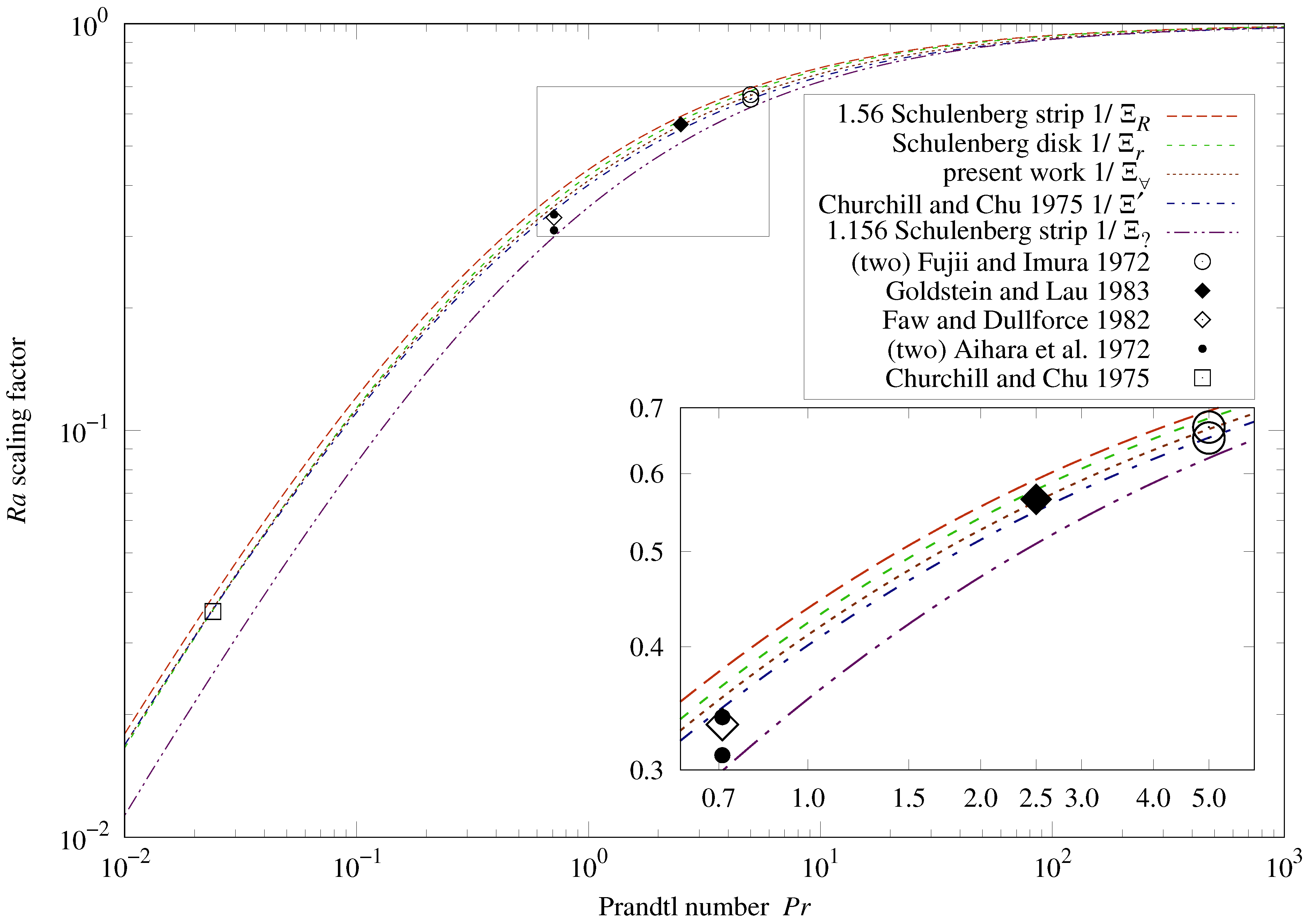
12. Ra Scaling Factors
Figure 4 presents the
scaling functions
used in the vertical and downward-facing formulas. Also shown are
values calculated from coefficients fitted to measurements in the cited sources.
Table 5 lists each fitted
value and its deviation from each
scaling function at the given
. Churchill and Chu
is closest to the fitted values.
If a candidate formula is correct, negative deviations of fitted (aggregate) values can result from flow obstructions or measurement bias; positive deviations can result only from measurement bias.
The positive
deviations,
and
, would indict two of the five sources in
Table 5. The positive
deviations,
and
, are tolerable.
With values between those of and , is the most plausible of these scaling functions.
The “1.156 Schulenberg strip
” curve in
Figure 4 is the
scaling function from Formula (
3).
Section 3 argues that this formula from Schulenberg [
14] contained a typographical error. Being 40% less than the other curves at
corresponds to Formula (
3) taking values 10% less than (corrected) Formula (
4).
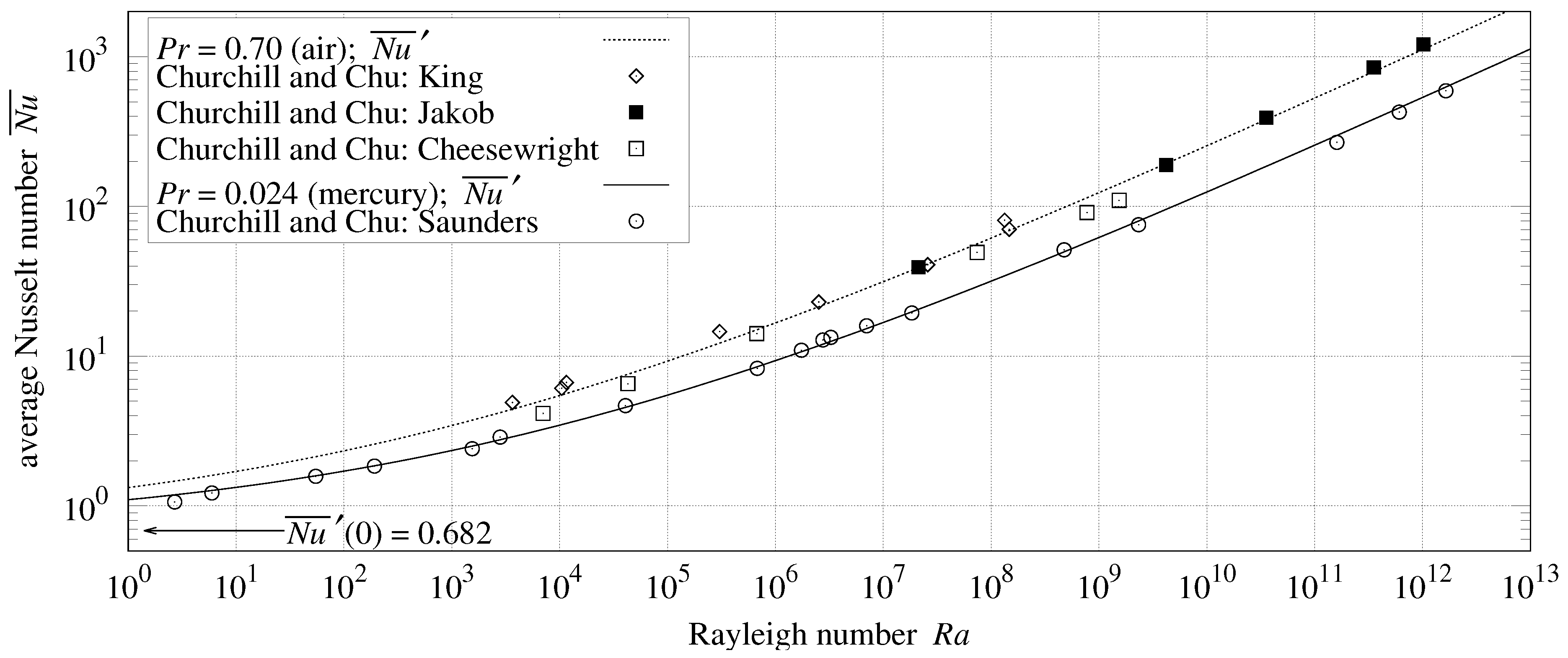
13. Vertical Measurements
Figure 5 and
Table 6 present four data-sets from Churchill and Chu [
5]. Differences between RMSRE computed from
Formula (
55) and Churchill and Chu Formula (
2) are less than 1%.
14. Downward-Facing Measurements
15. Characteristic Length Metrics
For upward convection, (area-to-perimeter ratio) is well-defined for any flat, convex plate.
The formulas for vertical (
55) and downward convection (
56) were developed for rectangular plates. More general characteristic length metrics are needed to model heat transfer from other plate shapes.
The next sections develop new characteristic length metrics for vertical and downward-facing plates, and re-derive the formulas for
(
30),
(
55), and
(
56) from alternative plate shapes.
16. Downward-Facing Circular Plate
Schulenberg Equations (
4) and (
5) for downward-facing strips and disks have matching exponents, but their coefficients and characteristic lengths differ:
is
of the rectangle’s shorter side, versus disk radius
R. Can
Formula (
56) predict heat transfer for both shapes using a single characteristic length metric?
16.1. Harmonic Mean
Figure 1b shows fluid closest to the heated surface flowing outward from the mid-line. If the plate edge is at varying distances from the mid-line (in the direction of flow), then some sort of length averaging is needed. The flow will be faster over shorter distances because it experiences less drag; this suggests the use of the “harmonic mean”, in which small values have more influence than large.
For rectangles and disks, the mid-line is one of the plate’s equal-area bisectors. For rectangles it is parallel to the longer sides; but it is not the longest bisector, which is diagonal. Being parallel to the longer sides implies that the mid-line is perpendicular to the shorter sides. It will also be perpendicular to the shortest equal-area bisector; and this works for disks as well, where all diameters are bisectors.
Consider a flat heated surface with its convex perimeter defined by functions
and
within the range
along the equal-area bisector which is perpendicular to the shortest equal-area bisector. Let
be the combined harmonic mean of
and
:
For rectangular plates,
Formula (
57) is
of the shorter side’s length, the same characteristic length used by Schulenberg [
14]. For disks of radius
R:
Schulenberg’s disk Formula (
5) used radius
R as the disk’s characteristic length. Converting the
coefficient from characteristic length
R to
is
, which is within 3% of the 0.550 coefficient of
Formula (
56).
16.2. Recalculate Conduction
The derivation of downward Formulas (
46) and (
56) was for a square plate. To derive the downward formula for a disk,
will be recalculated; it will be scaled larger because of the increased flow over shorter distances. Recalling from
Section 7, the conduction shape factor for one side of a disk is
.
Upward-facing disk
was scaled by
in Formula (
27) because its flow was midway between parallel and radially inward; downward-facing
was unscaled in (rectangle) Formula (
44). The flow from a downward-facing disk spreads from a diameter; an intermediate scale is needed. The geometric mean of 1 (unscaled) and
is
. Scaling
by the reciprocal,
, yields the rectangular
. With the
harmonic mean metric (
57) and
, the rest of the derivation is unchanged. Thus, the downward Formula (
56) works for both rectangular and circular plates.
16.4. Rectangle Shape Factor
derives an exact expression for the rectangular plate’s dimensionless shape factor
:
17. Vertical Circular Plate
Consider a flat vertical plate as an array of narrow vertical plates. With
, integrate
h across the vertical slices of heights
; then solve for
in
:
Therefore, the vertical characteristic length is the harmonic mean of vertical spans .
For a rectangle of height
L,
. For the disk of radius
R,
. Recalculating
:
Instead of the bifurcated flow from the downward-facing plate, flow is along full vertical spans of the disk; 1/2 of the diameter-to-circle fringing which scaled downward-facing disk
by
should apply to vertical disks. With this scaling,
, and the rest of the derivation is unchanged. Thus, the vertical Formula (
55) works for disks and axis-aligned rectangular plates using
harmonic mean Formula (
61).
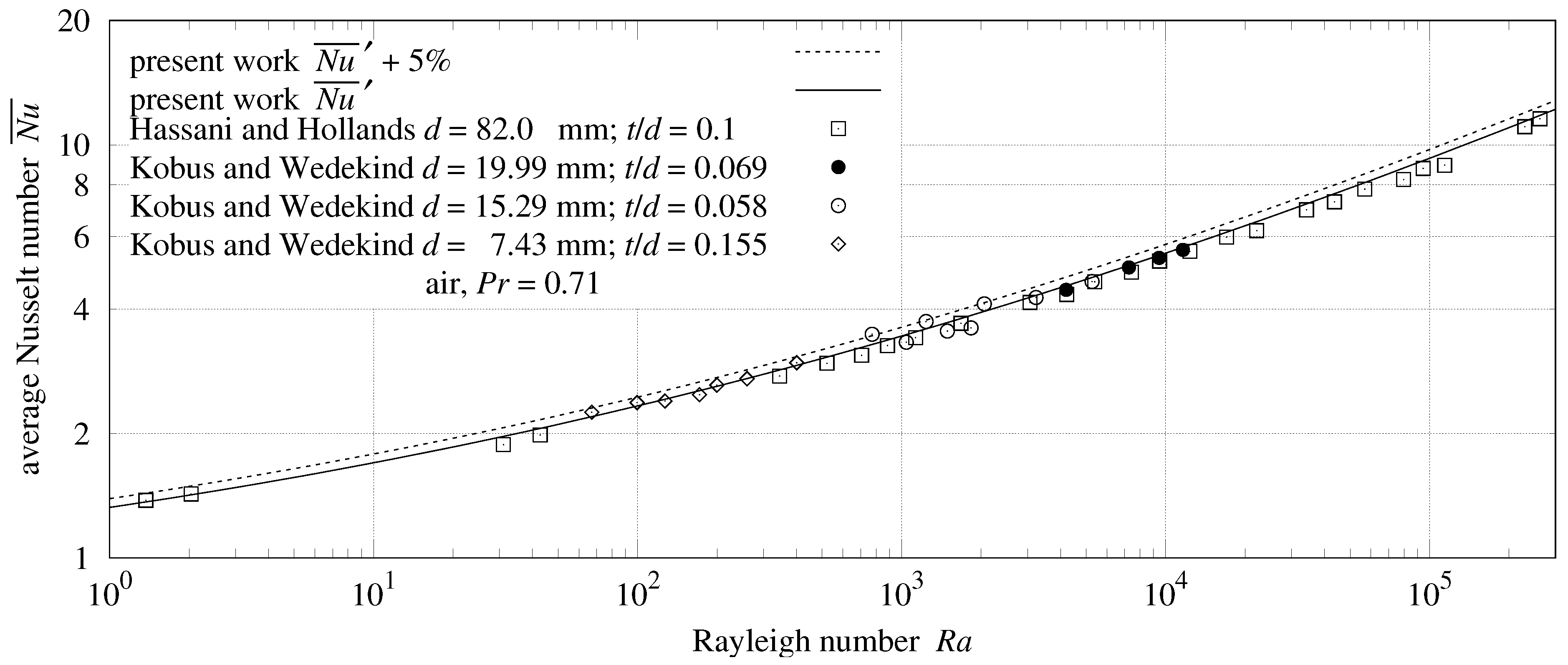
Measurements
Kobus and Wedekind [
9] measured natural convection heat transfer from vertical thermistor disks in air. They also included a series of similar measurements from Hassani and Hollands (1987).
was not specified; 0.71 is assumed. Each disk’s diameter
d and thickness
t are specified in
Figure 7.
Air heated by the two disk sides flows over the upper half of the rim, inhibiting upper-rim heat transfer. The lower half of the rim transfers heat at the same per-area rate as the sides. The disk effective surface area, including half of the rim, is
. Being normalized for the area,
should be scaled by:
To convert characteristic lengths to the harmonic mean, Kobus and Wedekind
gets scaled by
;
gets scaled by
and Formula (
63). Hassani and Hollands used different characteristic lengths for
and
; their
gets scaled by
, while
gets scaled by
and Formula (
63).
In the clever design using thermistors, only horizontal clearance and the wires attached to the disk centers remained as obstructions, achieving a close match with the present theory in
Table 8.
18. Upward-Facing Square Plate
Converting square plate
Formula (33) from
to
is divided by 4. Expanding
from Equation (
60):
The square plate’s flow will be moderately radial, scaling midway between the reciprocal of
from the upward-facing disk, and
from the downward-facing disk’s bifurcated flow. The geometric mean of
and
is
. Scaling
by
yields
from Equation (
21). The rest of the derivation is unchanged. Thus, the upward convection
Formula (
30) works for disks and square plates.
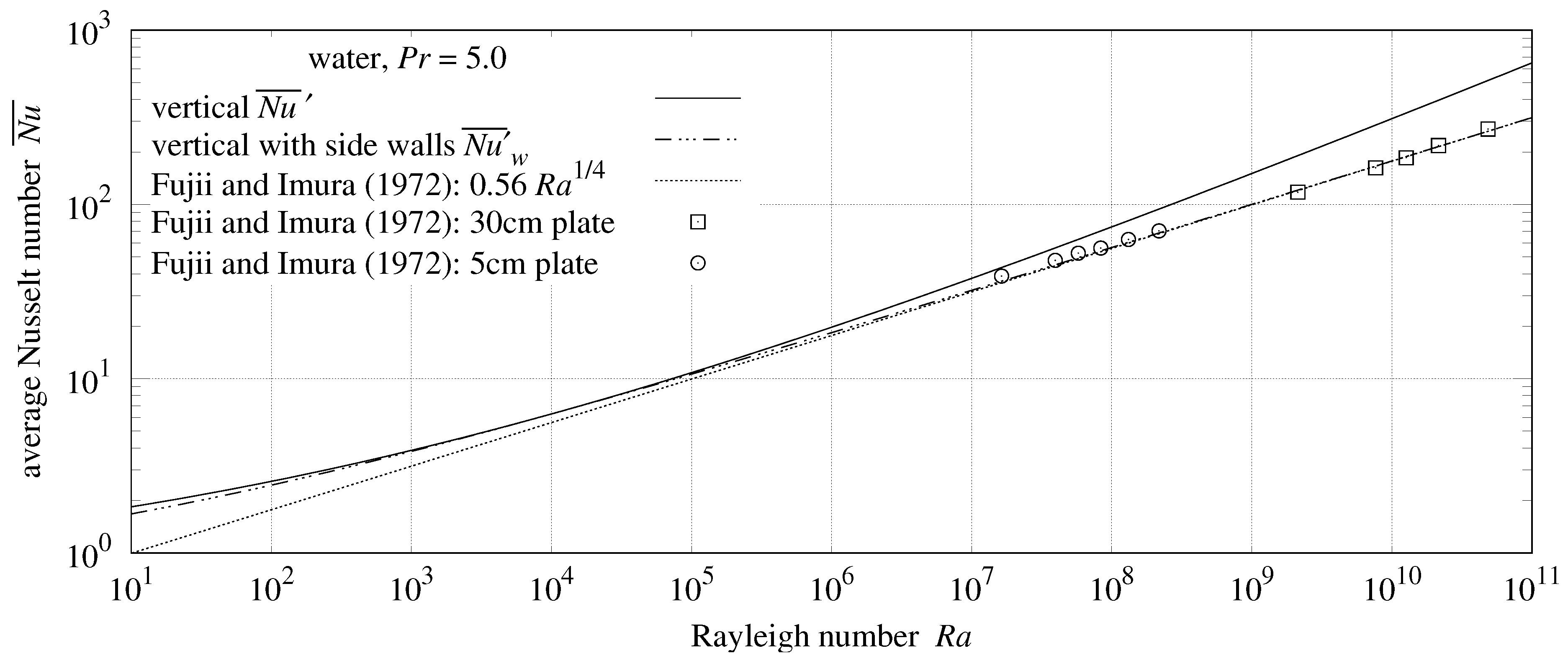
19. Vertical Rectangular Plate With Side Walls
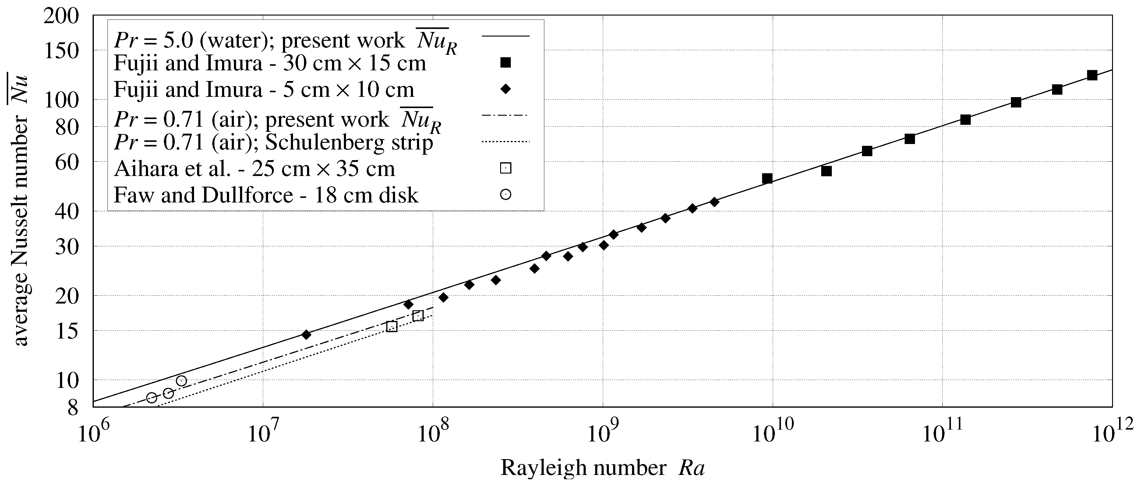
The Fujii and Imura [
1] apparatus had (unheated) perpendicular side walls of length
forming a channel with the plate. In
Table 9, the vertical 30 cm and 5 cm plates average 44% and 18% less heat transfer than expected by
vertical Formula (
55). Clearly, Formula (
55) is incorrect for vertical plates with side walls.
Formula (
65) incorporates an additional factor of
in
to model the side-wall drag. The side walls obstruct horizontal flow, so the combined length of flow along the plate and side wall is
; heat transfer contact along the plate is
L. The
-norm changes to the
-norm (addition):
Using the general Formula (48) with
,
, and
:
Table 9 details the performance of Formula (
67) for vertical plates with side walls. RMSRE of 2.2% and 5.2% are substantial decreases from 43.8% and 18.9%.
Figure 8 shows
, as required by efficiency constraints.
20. Upward-Facing Rectangular Plate With Side Walls
The area-to-perimeter ratio for side-walled upward-facing plates exclude side-wall length from the perimeter length () because there is no flow through side walls. Thus, .
In
Table 3 (and
Table 10), the Fujii and Imura data-sets averaged 0.4% and 11.4% less than expected from
Formula (
30). The 30 cm plate having side walls twice as long as its 15 cm channel width made its flow similar to vertical plate flow in each half of the plate towards the center line.
.
Fluid rises after heating; so the
and heat transfer factors are both
. As with the side-walled vertical plate, conduction and flow-induced heat transfer combine using the
-norm (addition):
Flow is partially obstructed by the side walls; hence,
will be scaled by
. Using the general Formula (48) with
,
,
,
, and
:
Note that, unlike
Formula (
30),
Formula (
70) depends on
.
Figure 9 and
Table 10 show that
Formula (
70) is effective for the 30 cm plate, but not for the 5 cm plate. The 5 cm plate’s 10 cm channel width is twice the 5 cm side-wall length. This makes its flow more radial than parallel. Thus,
Formula (
30) is more appropriate for the 5 cm plate.
Table 11 lists the general derivation Formula (48) parameters for the side-wall flow topologies.
21. Inclined Plate
Let be the angle of a plate from vertical. Face up ; vertical ; face down . This investigation has derived and tested formulas for rectangular and circular plates at , , and .
Following Fujii and Imura [
1], the
argument to vertical Formula (
55) gets scaled by
to model the reduced vertical convection from an inclined plate. (Fujii and Imura [
1] credits B. R. Rich with the idea of scaling vertical
by
. It can be thought of as a reduction in the effective gravitational acceleration
g, which scales
linearly.) Following Raithby and Hollands [
17], the
and
arguments to the upward and downward Formulas (
30) and (
56) get scaled by
.
Raithby and Hollands take the maximum convective surface conductance
, not
, to determine the overall convection. This is because
,
, and
have different characteristic lengths, while
is independent of
L. Taking the maximum asserts that the associated flow topologies are mutually exclusive. This extreme competition is the
-norm, which is equivalent to the
function when all its arguments are non-negative:
Rayleigh numbers can be expressed in terms of (vertical plate)
:
The downward-facing topology flows outward from opposite plate edges; there is no plate area available for the vertical flow topology. Thus,
and
are mutually exclusive in Formula (
72). The upward-facing topology draws fluid from the whole perimeter. Thus,
and
are mutually exclusive in Formula (73). Note that Formula (73) mutual exclusion may not hold when part of the perimeter flow is obstructed.
Ideally, when
,
should be independent of
. For a 1 m square plate in
fluid,
, but
. When
forces
to 0, only the conduction term remains. As noted in
Section 7.5,
Formula (
30) does not extend to static conduction.
and
track measurements well near
in
Figure 3,
Figure 5, and
Figure 7. Ignoring
when
, and
when
, avoids the conduction term competition at
:
Note that
and
are true for any flat, convex plate face.
With
, the proposed
Formula (
74) will match non-side-walled horizontal and vertical plate measurements to their appropriate
,
, and
values.
22. Inclined Plate With Side Walls
The Fujii and Imura [
1] apparatus had length
side walls. In
Table 7, the
Formula (
56) has less than 5% RMSRE; it is used as the side-walled downward-facing formula with
, regardless of which side is shorter.
To adapt
Formulas (
72) and (
73) to apparatus with side walls,
Formula (
67) replaces
. This leads to proposed downward
Formula (
75) for side-walled plates:
Fujii and Imura photographs show the plume originating in the middle of the 5 cm plate when . The origin shifts 9% toward the elevated end of the plate when . The plume for the 30 cm plate at originates in the upper 1/4 of the plate. Plume movement with indicates that regions of upward-facing and vertical convection shared the side-walled plate in the Fujii and Imura apparatus.
The side-walled upward and vertical topologies compete for horizontal flow in the channel. If competition were between perpendicular flows, they would combine as the root-sum-squared, which is the -norm. To compete for horizontal channel flow, two changes in direction are required; they combine as the -norm.
The 30 cm plate has side walls twice as long as its channel width
w. Flow through this channel will be primarily parallel, as modeled by
Formula (
70). The proposed upward
formula for the 30 cm plate is:
The 5 cm plate’s 10 cm channel is twice as wide as its length; the horizontal flow will be more radial than parallel. At
it is modeled by
Formula (
30), but with characteristic length
.
Fujii and Imura streamline photographs show the vertical and upward-facing flow modes having uniform rates of the horizontal flow between the lower heated plate edge and pause elevation .
Uniform horizontal flow is not the case for the 5 cm plate at . The horizontal flow is slower near the lower plate edge and increases with elevation. The plume lacks a clear origin. It does not match any flow topology described thus far.
The upward-facing flow topology has bilateral symmetry; there is no flow between the halves created by severing along a plane of symmetry. Thus, half of the upward-facing flow topology is also a flow topology. Its general Formula (48) parameters are the same as the upward-facing topology, except that
. The
flow topology is modeled as the
-norm of
and
, where
is the heat transfer from this half upward flow topology. The proposed upward
formula for the 5 cm plate is:
At
, heat transfer is
; so
. At
, it is
; so
. The transition between
and
depends on
,
w, and
. Dimensional analysis yielding Formula (78) localizes the transition to
, whose bounds are marked by arrows in
Figure 10a.
Table 7,
Table 9,
Table 10, and
Table 12 show that the present theory is sufficient to explain, with RMSRE between 2.2% and 6.0%, the Fujii and Imura heat transfer measurements of horizontal, vertical, and inclined plates.
23. Results
Table 13 summarizes statistics for the eighteen data-sets presented in
Figure 3,
Figure 5,
Figure 6,
Figure 7,
Figure 8,
Figure 9 and
Figure 10, and their associated tables. They are grouped by orientation and ordered by decreasing error relative to the present work, All but three of these data-sets have RMSRE of 6% or less, quantitatively supporting the present theory for horizontal, vertical, and inclined plates.
24. Discussion
Rennó and Ingersoll [
12] and Goody [
13] found that the heat-engine efficiency limit for atmospheric convection is 1/2 of the reversible heat-engine efficiency limit
. This investigation finds that
is the limit for external natural convection generally. Reversible heat engines, such as Stirling engines, can be more efficient than
. External convection is not reversible.
The Fujii and Imura [
1] side-walled plates do not qualify as external because fluid was not free to flow horizontally near the plate. The side wall formulas are not general, particularly for square plates. They were investigated primarily to gauge how well the combination of
-norm with trigonometric scaling of
explains heat transfer from inclined plates.
Evidence from Lloyd and Moran [
4], and statements in Fujii and Imura [
1] and Churchill and Chu [
5], that the laminar-turbulent transition was irrelevant to natural convection heat transfer were published in the early 1970s. Yet, the belief that it governs external plate natural convection heat transfer has persisted [
2,
11,
17].
Much of the subsequent natural convection literature investigates local flow properties. Such studies do not inform this investigation’s systemic-invariant analysis. However, streamline photographs were crucial to characterizing the flow topologies and deriving the present formulas.
The pause in horizontal flow above the upward-facing 5 cm plate is visible in the
photograph from Fujii and Imura [
1]. Their photographs of vertical and downward-facing plate streamlines do not include enough of the fluid above the plates to see the horizontal pause expected by this investigation.
The harmonic mean integral in Formulas (
57) and (
61) converges only when the perimeter curve is perpendicular to the integration axis at both integration limits. For downward-facing plates this includes all circles, ellipses, and rectangles; for vertical plates, this includes all circles and ellipses, and trapezoids (including rectangles) with two vertical edges. When
, vertical plate
scales with
. Hence, the heat flow rate
is sensitive to
only at small
values.
25. Conclusions
Using a novel methodology based on streamline photographs, dimensional analysis, and the thermodynamic constraints on heat-engine efficiency, this investigation:
Derived from first principles a previously unknown comprehensive heat transfer formula for upward-facing convection;
Extended the scope of vertical and downward-facing formulas from rectangles to other shapes with convex perimeters using the harmonic mean for the characteristic length metric;
Unified the dependence of vertical and downward-facing plates.
A comprehensive and exact model for natural convection from an external, isothermal flat surface can now be succinctly stated. For horizontal upward-facing plates:
For vertical and downward-facing plates, the convection reduction due to self-obstruction is the
scaling factor
, yielding comprehensive formulas for vertical
and downward
:
The reduction in effective gravitational acceleration
g also scales
. The average convective surface conductance for an external, isothermal plate inclined at angle
from vertical is:
The upward-facing characteristic length is the area-to-perimeter ratio.
The vertical characteristic length is the harmonic mean of the perimeter vertical spans.
The downward-facing characteristic length is the harmonic mean of the perimeter distances to that bisector which is perpendicular to the shortest bisector.
is the Rayleigh number computed with vertical characteristic length .
; and .
The harmonic mean metrics extend vertical and downward-facing to non-rectangular plates.
The present theory was compared with eighteen data-sets from seven peer-reviewed articles, testing circular, rectangular, and inclined rectangular plates, laminar and turbulent flows, with and . All except three of the data-sets had between 2% and 6% RMSRE from the present theory.
The formula improves accuracy and range substantially over the piece-wise power laws currently employed for predicting upward convection heat transfer.
With less than 1% difference between and the Churchill and Chu (1975) vertical formula, there is little need to replace it in existing applications.
However, the published Schulenberg (1985) formula can return values which are 10% smaller than ; should replace it.


