Article

Towards Single-Polymer-Based Fully Printed Textile-Based Flexible Ag2O-Zn Battery for Wearable Electronics

by
Akash Kota
1,*,
Kavya Vallurupalli
2,
Amy T. Neidhard-Doll
3 and
Vamsy P. Chodavarapu
3
1
Octet Scientific, Inc., Cleveland, OH 44103, USA
2
Master Builders Solutions Construction Systems, Beachwood, OH 44122, USA
3
Department of Electrical and Computer Engineering, University of Dayton, Dayton, OH 45469, USA
*
Author to whom correspondence should be addressed.
Textiles 2024, 4(2), 256-266; https://doi.org/10.3390/textiles4020015
Submission received: 5 February 2024 / Revised: 17 April 2024 / Accepted: 16 May 2024 / Published: 19 May 2024
(This article belongs to the Special Issue Advances in Smart Textiles)

Abstract

:
Printed textile-based flexible batteries are gaining attention in several applications, but they are becoming more relevant to the health care industry in terms of realizing wearable and skin-conformable electronic devices. A flexible battery must ideally be deformable along multiple directions. In this work, with an aim to develop a fully printed omnidirectional deformable battery, we report the fabrication process of a novel single-polymer-based flexible non-rechargeable planar Ag2O-Zn battery on a textile substrate using the stencil printing method. Except for the electrolyte, all the components of the battery, including the current collectors, the anode, the cathode, and the separator membrane, are fabricated using a single polymer, namely styrene–ethylene–butylene–styrene (SEBS). To fabricate the SEBS separator, we introduce the solvent evaporation-induced phase separation (SEIPS) process. In the SEIPS method, toluene and dimethyl sulfoxide (DMSO) are selected as the solvent–nonsolvent pair. The SEBS: toluene: DMSO system with a wt% ratio of 6:85:9 showed improved performance regarding the OCV tests. A polyacrylic acid (PAA)-based alkaline polymer gel is used as an electrolyte. The demonstrated process is simple, and, with suitable modifications, it should find its use in the development of digitally printed alkaline batteries.

1. Introduction

As the applications for wearable electronics continue to increase, the need for the integration of built-in energy storage devices such as batteries and supercapacitors that can endure deformation while retaining the performance and safety is becoming more important. Specifically, batteries with flexible and stretchable properties are gaining attention for powering wearable systems such as electronic skin [1], implantable medical devices [2], strain sensors [3], and smart bandages [4]. The flexible and stretchable energy storage devices that have been previously reported in the literature can be broadly categorized into two groups: (1) unidirectional and (2) omnidirectional deformable batteries [5]. Unidirectional deformable or “bendable” batteries are targeted for wearable electronics with limited contact to human skin and possess moderate flexibility. To this end, a variety of lithium-ion batteries (LIBs) with cathode materials such as lithium cobalt oxide (LCO), lithium manganese oxide (LMO), and lithium titanium oxide, etc., [6] have been widely researched to demonstrate unidirectional deformable batteries due to their high energy density characteristics. In our previous work, we demonstrated a printed unidirectional deformable Ag2O-Zn battery using styrene butadiene rubber (SBR) as the anodic binder [7]. In contrast, omnidirectional deformable or “soft” batteries are targeted for wearable health monitoring systems that are directly attached to human skin and possess high flexibility, high safety, and medical compatibility. Due to the rigorous safety requirements, aqueous electrolyte-based alkaline energy storage systems such as Ag2O-Zn batteries are preferred over their lithium counterparts.
In an omnidirectional deformable battery, each individual component, including the current collectors, anode, cathode, separator, electrolyte, and encapsulation layers, must be deformable along multiple directions. In the prior literature, flexible and stretchable Ag2O-Zn batteries have been demonstrated using different approaches. One approach is to use elastic polymers as binder materials during the synthesis of electrode inks. Using this approach, R. Kumar et al. [8] demonstrated a printed highly stretchable planar Ag2O-Zn battery that employs styrene–isoprene–styrene (SIS) as the binder material. In this work, the current collector and electrode inks are prepared using the SIS polymer. The outline of the printed electrodes is hot-sealed with a polyurethane (PU) sheet that acts as a separator. The sealed battery is loaded with a polyacrylic acid (PAA)-based gel electrolyte. A highly elastic thermoplastic polyurethane (TPU) film is used to encapsulate the battery. Using a similar approach, L. Yin et al. [9] demonstrated a high-performance flexible and stretchable vertically assembled rechargeable Ag2O-Zn battery that uses SEBS and fluorine rubber as the elastomeric binders. In this work, the silver current collectors are prepared using the SEBS polymer. The carbon current collectors and the electrode inks are prepared using fluorine rubber. The separator ink is prepared using cellulose and titanium powders. The electrolyte hydrogel is prepared using polyvinyl alcohol (PVA) and polyethylene oxide (PEO) polymers.
To demonstrate printed batteries, techniques such as stencil, screen, inkjet, gravure, extrusion, and direct write dispenser printing have been used [10,11,12,13]. Each printing process varies in terms of the ink requirements, print resolution, and achievable throughput. Each technique has its advantages and disadvantages. For instance, inkjet printing enables the printing of customizable patterns but suffers from low throughput [14]. The ink or slurries used to print the individual battery components can have high viscosities ranging from 0.05 to 10,000 Poise. The size of the particles in the ink can be in the range of 1 to 20 μm [15]. The inks are typically a suspension consisting of electrochemically active materials, a solvent, and a polymer. The rheological properties, such as the viscosity and shear modulus of the ink, are highly dependent upon the type of the solvent and molecular weight of the polymer used. The viscoelastic properties of the inks must be tailored to meet the requirements of the printing technique used. If multiple different polymers are chosen to fabricate the different components of the battery, the process of optimizing the inks for printing becomes complex and remains challenging.
In the existing literature, to fabricate the individual components in an omnidirectional deformable Ag2O-Zn battery, a number of different polymers are required. To simplify the battery printing process in this work, we report the fabrication process of a novel single-polymer-based, flexible planar Ag2O-Zn battery using the stencil printing method. Except for the electrolyte, all the components of the battery are fabricated using the styrene–ethylene–butylene–styrene (SEBS) polymer. To fabricate the separator, we introduce the solvent evaporation-induced phase separation (SEIPS) process. The SEIPS process is scalable and enables the printing of the separator membrane directly on the surface of the electrodes.

2. Materials and Methods

2.1. Materials Used

Textile Substrate: An 80% polyester 20% spandex (Joann Fabrics, Fairborn, OH, USA, serial number 1638-0750) fabric was used as the textile substrate to print different components of the battery.
Polymer: To prepare different components of the battery, SEBS (Kraton Polymers, Houston, TX, USA, serial number G1654) was used as an elastic polymer. SEBS is a hydrophobic polymer.
Conductive Filler: Artificial graphite powder (MTI Corporation, Richmond, CA, USA, serial number EQ-Lib-CMSG) and super P carbon (SP) (MSE Supplies, Tucson, AZ, USA, serial number BR0121) were used as conductive filler materials.
Solvent: To dissolve SEBS, toluene (Sigma-Aldrich, Milwaukee, WI, USA, serial number 179418) was used as the solvent.
Electrodes: To prepare the electrode inks, silver oxide (Ag2O) (Sigma-Aldrich, Milwaukee, WI, USA, serial number 221163), zinc (Zn) (Sigma-Aldrich, Milwaukee, WI, USA, serial number 209988), zinc oxide (ZnO) (Sigma-Aldrich, Milwaukee, WI, USA, serial number 205532), and bismuth oxide (Bi2O3) (Sigma-Aldrich, Milwaukee, WI, USA, serial number 223891) powders were used.
Separator: To prepare the separator membrane, dimethyl sulfoxide (DMSO) (Sigma-Aldrich, Milwaukee, WI, USA, serial number 276855) was used.
Electrolyte: To prepare the gel electrolyte, potassium hydroxide (KOH) (Sigma-Aldrich, Milwaukee, WI, USA, serial number 484016), lithium hydroxide (LiOH) (Sigma-Aldrich, Milwaukee, WI, USA, serial number 545856), PAA (Sigma-Aldrich, Milwaukee, WI, USA, serial number 306215), ZnO, and distilled water were used.

2.2. Preparation of Current Collector and Electrode Inks

The SEBS-based inks were prepared by first dissolving 6 g of SEBS beads in 15 mL of toluene with a magnetic stirring mixer for 24 h at 400 rotations per minute (rpm). This mixture was used as the base solution to prepare the current collector and electrode inks. Toluene was chosen as the SEBS solvent due to their similar Hildebrand solubility parameters. To prepare the elastic carbon current collector ink, first, 0.8 g of carbon composite powder constituting 14.25 wt% SP and 85.75 wt% artificial graphite powder was prepared. Graphite powder and SP were thoroughly mixed using pestle and mortar. Then, carbon slurry was prepared by adding 0.960 g of base solution and 0.240 g of toluene to 0.8 g of carbon composite powder. To obtain a homogenous blend, the carbon slurry was mixed using a planetary centrifugal mixer at 2000 rpm for 5 min.
To prepare the elastic Zn ink, first, 2 g of Zn composite powder constituting 70 wt% Zn, 10 wt% Bi2O3, 15 wt% graphite powder, and 5 wt% SP was prepared. Graphite powder, SP, Zn, and Bi2O3 powders were thoroughly mixed using pestle and mortar. Then, Zn slurry was prepared by adding 0.400 g of base solution and 0.120 g of toluene to 0.480 g of Zn composite powder. To achieve a homogenous blend, the Zn slurry was mixed using a planetary centrifugal mixer at 2000 rpm for 3 min.
To prepare the elastic Ag2O ink, 1 g of Ag2O composite powder constituting 80 wt% Ag2O, 15 wt% graphite powder, and 5 wt% SP was prepared. Graphite powder, SP, and Ag2O powders were thoroughly mixed using pestle and mortar. Then, Ag2O slurry was prepared by adding 0.400 g of base solution and 0.120 g of toluene to 0.480 g of Ag2O composite powder. To obtain a homogenous blend, the Ag2O slurry was mixed using a planetary centrifugal mixer at 2000 rpm for 3 min.

2.3. Preparation of Separator Solution

To prepare the separator solution, first, 1 g of SEBS beads were dissolved in 15 g of toluene with a magnetic stirring mixture for 6 h. While the solution is being stirred, 1.5 g of DMSO was slowly added to the mixture using a pipette. The resulting solution was stirred for 3 h to ensure a homogenous blend.

2.4. Preparation of Gel Electrolyte

The gel electrolyte was prepared by mixing 3 wt% PAA with ZnO-saturated 6 M KOH + 1 M LiOH solution using a magnetic stirring mixer for 30 h at 400 rpm. The selected PAA has a Mw~1,250,000 g/mol. To prepare 6 M KOH solution, 3.36 g of KOH pellets were dissolved in 10 mL of distilled water. To prepare 1 M LiOH solution, 0.240 g of LiOH powder was dissolved in 10 mL of distilled water. To prepare 20 mL of 6 M KOH + 1 M LiOH solution, 10 mL of 6 M KOH solution was added to 10 mL of 1 M LiOH solution. Appropriate amount of ZnO was added to 6 M KOH + 1 M LiOH solution and stirred until saturation. The resulting solution was left undisturbed for 24 h such that the excess ZnO particles settle down in the beaker. To prepare 5 g of 3 wt% PAA-based gel electrolyte, 0.15 g of PAA was added to 4.85 g of ZnO-saturated 6 M KOH + 1 M LiOH solution.

2.5. Characterization Methods

The electrical conductivity of the printed conductive tracks was measured by using a four-point probe method (Ossila, Sheffield, UK, serial number T2001A3). Rheology experiments were performed to determine the viscosity, storage, and loss moduli of the gel electrolyte using Anton Paar rheometer (Anton Paar, Ashlan, VA, USA, serial number MCR302) in concentric cylinder configuration. The battery characterization experiments were performed using Neware battery cycler (Neware Technology, Shenzhen, China, serial number BTS 4000).

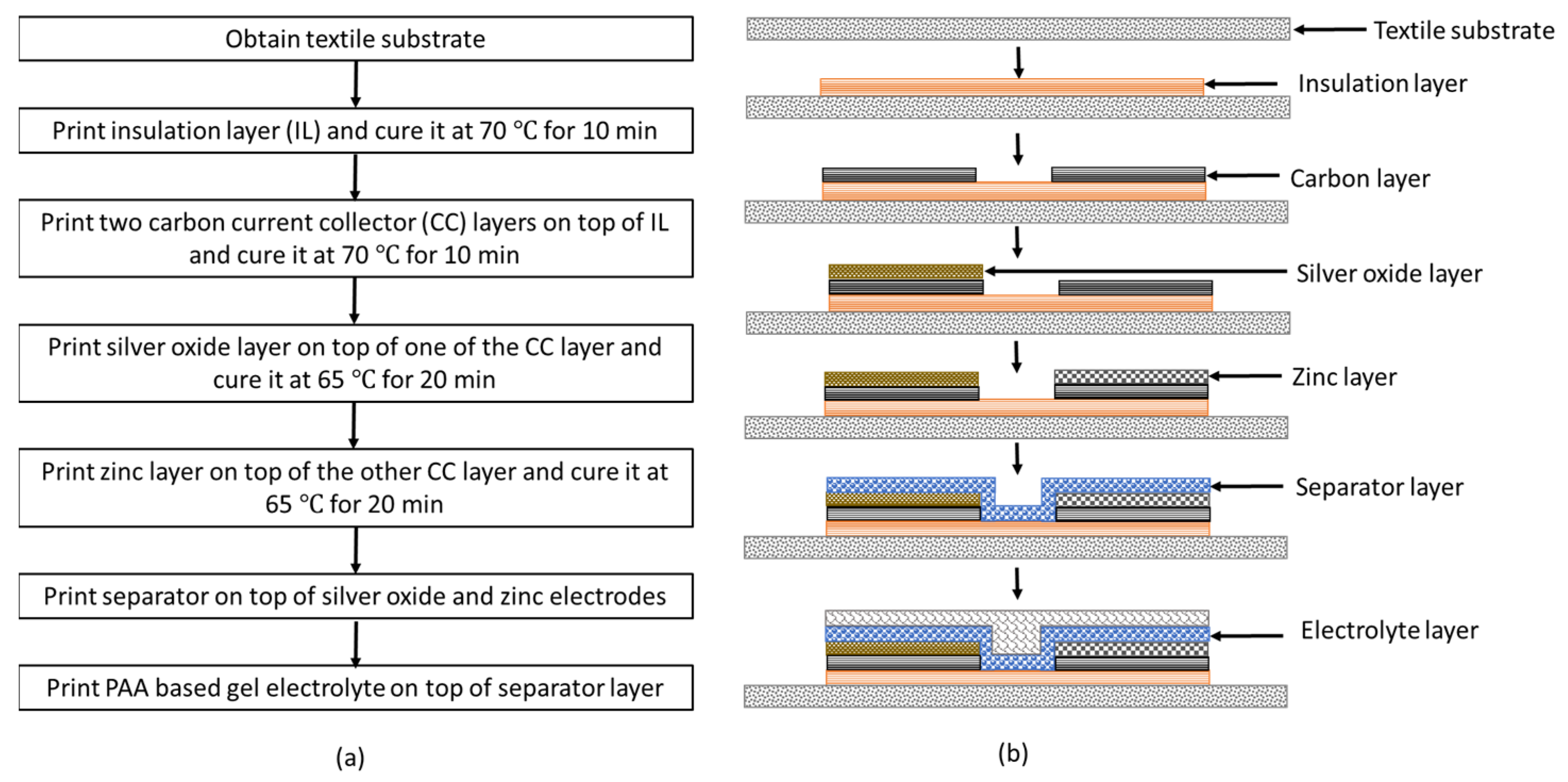
3. Battery Fabrication Procedure

For printing the insulation layer, current collectors, electrodes, and separator stencil patterns were designed using SolidWorks 2020 software (SolidWorks, Waltham, MA, USA). To print different layers, stencils with two different thicknesses were used. The stencil material was composed of polyamide-nylon 6 (PA 6). The stencils were engraved with the required patterns using a CO2 laser (Boss Laser, Sanford, FL, USA, serial number LS1416). The thickness of the stencils was designed to be 200 μm (Goodfellow, Coraopolis, PA, USA, serial number AM301200) for the insulation layer, the current collectors, and the separator, and 350 μm (Goodfellow, Coraopolis, PA, USA, serial number AM301350) for the electrodes. The individual layers were stencil-printed using a 6-inch metal squeegee.
The battery printing process is described in the following steps. First, a textile substrate of size 5 cm × 5 cm is obtained. To prevent the leakage of the gel electrolyte into the fabric, an insulation layer of size 2 cm × 2 cm using SEBS base solution is printed on the fabric. To evaporate the solvent, the printed insulation layer is cured in a vacuum oven at 70 °C for 10 min. Then, two carbon current collector layers of size 2 cm × 0.5 cm are printed onto the insulation layer and cured at 70 °C for 10 min in a vacuum oven. The spacing between the current collector layers is 0.5 cm. To print the cathode, using the Ag2O slurry, an electrode layer of size 1 cm × 0.5 cm is printed onto one of the current collector layers and cured at 65 °C for 20 min in a vacuum oven. Similarly, to print the anode, Zn slurry is printed onto the other current collector layer and cured at 65 °C for 20 min in a vacuum oven. After printing the electrodes, the separator solution is printed onto the electrodes and cured at room temperature for 24 h. The gel electrolyte is then printed onto the separator layer. The step-by-step illustration of battery fabrication procedure is shown in Figure 1a. The cross-sectional view of the corresponding printed layer at each fabrication step is shown in Figure 1b.

4. Results and Discussion

4.1. Electrical Conductivity Measurement

The electrical conductivity σ   S / m of the printed conductive tracks was measured by using the four-point probe method. The dimensions of the long side and short side of the conductive tracks were 20 mm and 5 mm, respectively. To ensure repeatability, three identical conductive tracks were printed, and each track was considered as a sample. Washability tests were performed to evaluate the durability of the conductive tracks. The printed carbon tracks were washed in cold water using a portable washing machine. The duration of each wash cycle is 15 min. For each sample, three conductivity measurements were recorded, both before and after two, four, six, and eight wash cycles. The average values were reported in Table 1. The corresponding sheet resistance ρ   Ω / values were reported in Table 2.
From Table 1, it can be observed that, for up to eight wash cycles, an increasing trend in the conductivity was observed on all three samples. However, after twelve wash cycles, the conductivity decreased. This suggests that the conductivity is not homogeneous in the stencil-printed tracks.
From Table 2, it can be observed that, in all three samples, after subjecting the carbon tracks to washability tests, there was no significant change in the sheet resistance values. For instance, the sheet resistance of sample 1 before wash was 4.2 Ω / . After two, four, eight, and twelve wash cycles, the corresponding sheet resistance values were 4.3 Ω / , 4.4 Ω / , 4.0 Ω / , and 4.3 Ω / , respectively. Therefore, it can be concluded that, after 3 h of cold-water wash, no significant differences in the sheet resistance were observed across the samples. These experiments confirm that the printed conductive tracks are both flexible and durable.

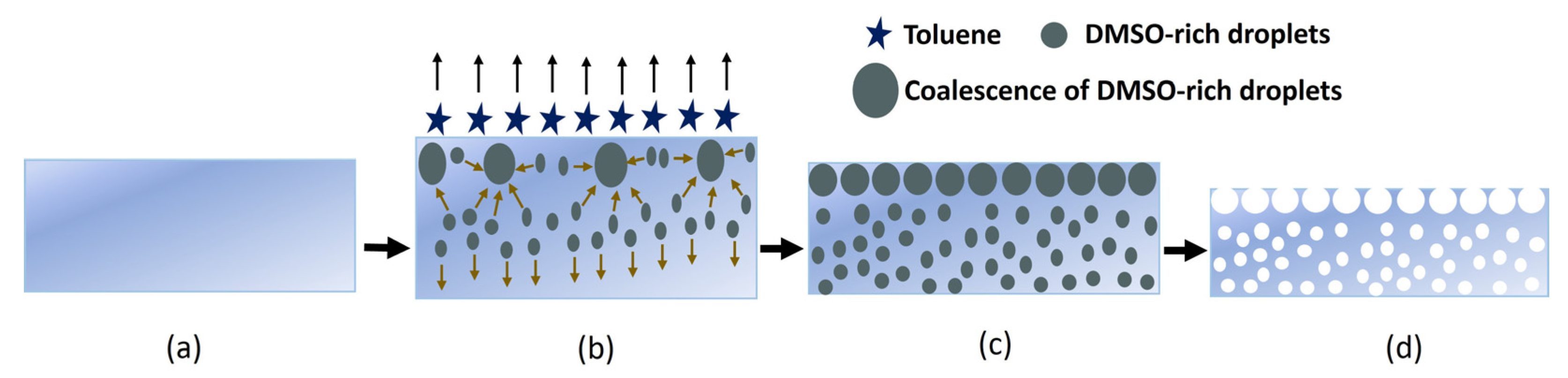
4.2. Separator Characterization

The development of high-porosity separators to provide the electrical insulation between the electrodes is essential for the fabrication of flexible batteries. In this work, to prepare the separator membrane, a scalable SEIPS method is introduced [16,17,18,19,20,21]. In this method, the phase separation takes place upon the evaporation of the solvent in a mixture of a polymer dissolved in a volatile solvent and a less volatile nonsolvent. In comparison to the other phase separation methods, the SEIPS method is simple and highly reproducible. However, the difficulty in finding a suitable solvent and nonsolvent pair for each polymer is a well-known disadvantage [22]. Here, we selected toluene as the solvent and DMSO was used as the nonsolvent. The step-by-step illustration of the pore formation in the SEBS separator membrane is shown in Figure 2.
As illustrated, DMSO was added dropwise into a mixture of SEBS and toluene under continuous stirring. The mixture was then stencil-printed on a glass slide and dried at room temperature for 1 h. During the evaporation process, the clear mixture becomes turbid due to the phase separation between the DMSO and SEBS. After the complete toluene evaporation, the resulting film was dried under a fume hood to evaporate the remaining DMSO.
In the SEIPS method, the pore growth mechanism can be mainly divided into three parts: (a) the evaporation of the solvent phase (toluene) and formation of nonsolvent-rich droplets (DMSO), (b) the complete evaporation of the solvent (toluene) and growth of nonsolvent-rich droplets (DMSO) through the entire membrane’s thickness, and (c) the evaporation of the nonsolvent (DMSO) phase. The pore formation begins after stencil printing the separator solution on the glass substrate. The solvent starts to evaporate, and phase separation occurs at the solution/air interface, where the wt% of toluene decreases and the wt% of the SEBS and DMSO increases. This in turn induces a flow of low-molecular-weight (MW) fluid ( M w D M S O = 78.13   g / m o l < M w T o l u e n e = 92.14   g / m o l ) into the zones with low polymer concentrations, leading to the formation of DMSO-rich droplets [23]. The evaporation of the solvent rapidly cools off the surface and causes a temperature gradient between the top and bottom of the casting solution. The convective flow downward and the solvent diffusion upward regarding evaporation help to accelerate the formation of the DMSO-rich droplets.
The pore growth mechanism is guided by three important parameters. The first parameter is the miscibility of the solvent and nonsolvent pair. DMSO is a widely used polar solvent that is miscible with polar and nonpolar compounds. The miscibility of common solvents can be found from the Hansen solubility parameters [24]. For uncommon solvents, their miscibility can be predicted by employing the same rules for solubility, calculated by the Hansen solubility parameter distance R a [25,26]. The R a can be calculated as
R a = 4 δ d s δ d N S 2 + δ p s δ p N S 2 + δ h s δ h N S 2 ,
where δ d , δ p , and δ h are the dispersive (Van der Waals), polar, and hydrogen bonding parameters of a liquid, respectively. S–NS denotes the solvent and nonsolvent pair. Using the Hansen solubility parameters ( δ d , δ p , and δ h ), the Hildebrand ( δ t ) solubility parameter can be calculated as
δ t = δ d 2 + δ p 2 + δ h 2 .
In Table 3, the Hansen, Hildebrand solubility parameters, corresponding miscibility R a values with toluene, and relative evaporation rates (RER) to n-butyl acetate for seven different solvents are presented.
From Table 3, it is evident that, for the toluene (solvent) and DMSO (nonsolvent) pair, the R a value is 17.1 M P a 1 / 2 . Similarly, for the THF (solvent) and DMSO (nonsolvent) pair, the R a value can be calculated as 11.38 M P a 1 / 2 . The high R a value for the toluene and DMSO pair indicates that the two solvents have low affinity compared to the THF and DMSO pair. This property leads to a slow formation of DMSO-rich droplets and contributes to a porous membrane formation. The second factor contributing to porosity is the difference in the volatilities of the solvents. From Table 3, it is evident that the DMSO has a much lower evaporation rate, which explains the slow nucleation, growth, and coalescence of the DMSO. The third factor is the polymer concentration. A low polymer concentration reduces the solution viscosity and facilitates convection, which benefits the growth and coalescence of the DMSO-rich droplets. Considering these three factors, the SEBS: toluene: DMSO system having a wt% ratio 6:85:9 resulted in the formation of a porous SEBS membrane desirable for the battery.

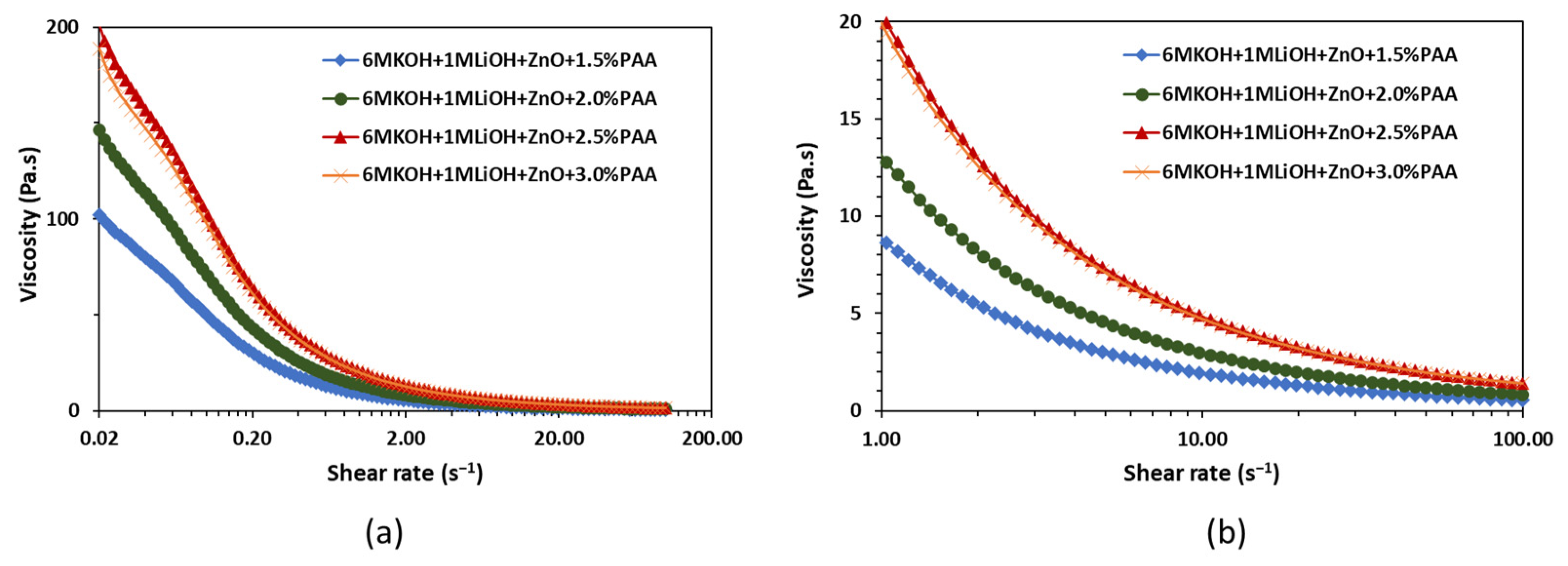
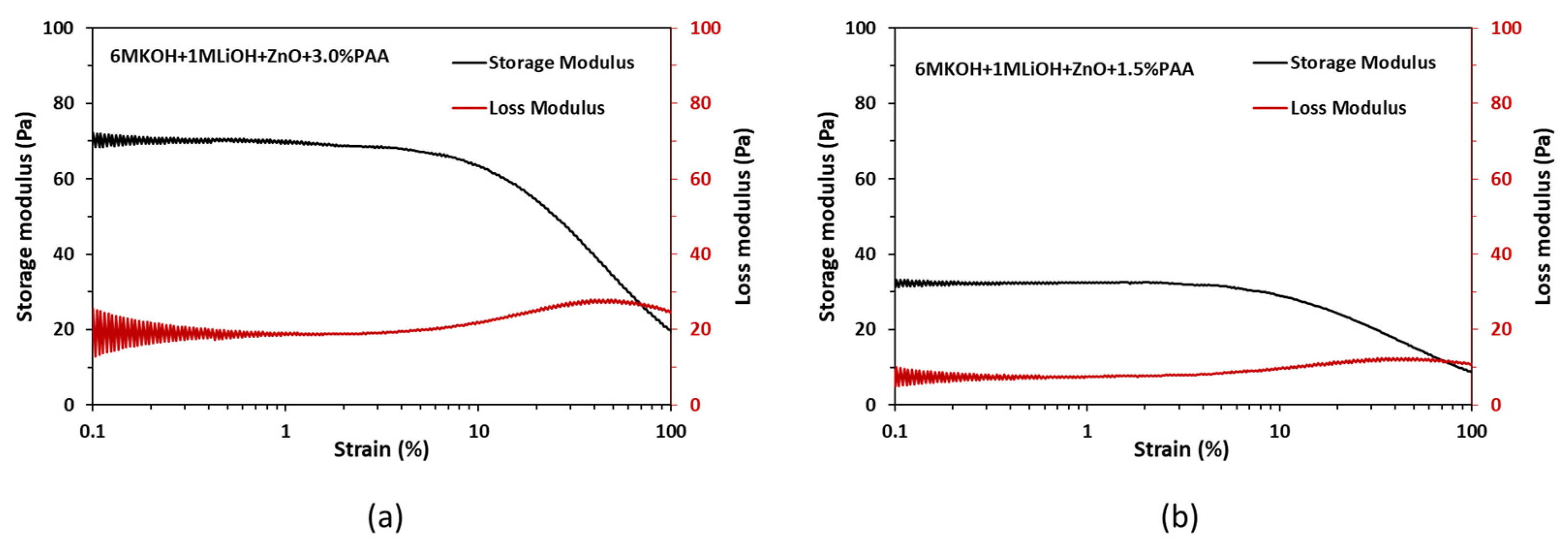
4.3. Rheology Characterization

The rheology experiments were performed to evaluate the effects of printing and flexing on the PAA-based gel electrolyte. The viscosity, storage, and loss moduli measurements were conducted using a co-axial concentric cylinder rheometer. The inner and outer cylinders had diameters of 26.7 mm and 28.9 mm, respectively. Also, to avoid slippage during shearing, a serrated inner cylinder and a sandblasted outer cylinder were used. The viscosity of the gel electrolyte was measured by pre-shearing the electrolyte at 100 s 1 for 120 s and applying a logarithmic shear rate sweep from 0.02 to 100 s 1 for 60 s. The rheology tests were performed on 1.5 wt%, 2 wt%, 2.5 wt%, and 3 wt% PAA in ZnO-saturated 6 M KOH + 1 M LiOH electrolytes. All the tests were performed at 20 °C. The viscosity versus shear rate curves are shown in Figure 3.
Figure 3 shows that, independent of the PAA concentration, all four gel electrolytes exhibit high viscosity at lower shear rates and a decrease in viscosity with an increase in shear rate. This shear thinning behavior of the gel electrolytes plays an important role in the development of packaging protocols for the printed alkaline batteries. The high viscosity at low shear rates suggests the high resistance of the electrolyte to deformation, which can help with the shape stability after extrusion [27], while the low viscosity at high shear rates suggests that the electrolyte can be easily extruded during the printing process. As highlighted in Figure 3b, the shear thinning ability of the electrolyte increased with an increase in the PAA content from 1.5 wt% to 3.0 wt%. Electrolytes with higher shear thinning ability, i.e., 3.0 wt% PAA, were preferred for the printing process to improve the shape stability, reduce the possibility of leakages due to cell rupture, and enhance the extrudability during printing.
In addition to the viscosity measurements, oscillatory strain sweep experiments were performed on the gel electrolyte to assess the storage modulus and the loss modulus. For a viscoelastic material like the gel electrolyte, the storage modulus reflects the elastic behavior of the material when it is deformed, while the loss modulus indicates the flow behavior of the material when it is deformed. Oscillatory strain sweep experiments were performed on 1.5 wt% and 3.0 wt% PAA in ZnO-saturated 6 M KOH + 1 M LiOH electrolytes at a 1 Hz frequency with the strain rates ranging from 0.050% to 100% on a logarithmic scale. The obtained results are shown in Figure 4.
From Figure 4a,b, it can be observed that, independent of the PAA wt%, both the storage and loss moduli are constant within the strain range of 0.05% to 6%. The constant values of storage and loss moduli within this strain range indicate linear viscoelastic behavior for the gel electrolyte. Furthermore, the significantly higher storage modulus compared to the loss modulus within the strain range of 0.05% to 6% suggests that the electrolyte primarily behaves as an elastic material when subjected to deformation. These modulus results suggest that the gel electrolyte can withstand the deformation when a battery is flexed and returns to its original position when the flexing force is removed without significant loss in the structural integrity of the gel electrolyte.
Comparing Figure 4a,b, the increase in the PAA dosage from 1.5 wt% to 3.0 wt% resulted in an increase in the storage and loss moduli values by 115% and 170%, respectively. The higher values of storage and loss moduli for the gel electrolyte with 3.0 wt% PAA are preferred for the printing process as they ensure less damage during the flexing of the battery.

4.4. Battery Characterization

The experiments were performed to study the effect of a separator membrane on the open circuit voltage (OCV) of the printed battery. Two batteries, one with the separator membrane and another without the separator membrane, were fabricated. The OCV data were obtained for both the batteries. The obtained results are shown in Figure 5.
From Figure 5, it can be observed that, for a battery without the separator membrane, the OCV dropped from 1.5 V to 0.8 V in approximately 3 h. On the other hand, for a battery with the SEBS separator membrane, the OCV dropped from 1.5 V to 0.8 V in approximately 22 h. By stencil printing the separator membrane on top of the electrodes, a stable OCV was obtained for a duration of 18 h, whereas, for a battery without the separator membrane, the OCV was stable for only a duration of 2.5 h. Therefore, from the OCV data, it can be concluded that the SEBS separator membrane is porous enough to maintain the ionic contact and electrical insulation between the electrodes. This experiment confirms that the SEBS separator fabricated using the SEIPS method is functional and has the potential to enhance the battery performance.

5. Conclusions

We presented the fabrication process of a novel single-polymer-based flexible planar Ag2O-Zn battery on a textile substrate using the stencil printing method. The current collectors, electrodes, and the separator were fabricated using the SEBS polymer. The washability tests were performed to evaluate the durability of the conductive tracks and revealed that, after 3 h of a cold-water wash, no significant differences in the electrical conductivity and sheet resistivity values were observed. The SEBS separator membrane was fabricated using the SEIPS method. In the SEIPS method, toluene and DMSO were chosen as the solvent and nonsolvent pair because of their high miscibility value, a property that leads to the slow formation of DMSO-rich droplets resulting in the formation of a porous membrane. The separator solution constituting 6 wt% SEBS, 85 wt% toluene, and 9 wt% DMSO resulted in the formation of a porous SEBS membrane desirable for the battery.
The rheology tests demonstrated that the shear thinning ability of the gel electrolyte increased with an increase in the PAA content from 1.5 wt% to 3.0 wt%. Therefore, a gel electrolyte with higher shear thinning ability, i.e., 3.0 wt% PAA, is preferred for the printing process as it reduces the possibility of leakages due to cell rupture and enhances the extrudability during printing. The strain sweep experiments demonstrate that the increase in the PAA dosage from 1.5 wt% to 3.0 wt% resulted in an increase in the storage and loss moduli values by 115% and 170%, respectively. The higher values of storage and loss moduli ensure less damage to the gel electrolyte, with 3.0 wt% PAA during the battery flexing process. The OCV characteristics reveal that a battery with and without the SEBS separator membrane provides a stable OCV for durations of 18 h and 4 h, respectively. Hence, it can be concluded that the SEBS separator membrane is porous enough to maintain the ionic contact and electrical insulation between the electrodes.
This work successfully demonstrated a novel Ag2O-Zn battery fabrication process using the SEBS polymer, which can simplify the printing process of flexible Zn-based batteries on textile substrates. By utilizing this process, the resulting omnidirectional deformable aqueous Ag2O-Zn batteries can be a preferred alternative to lithium batteries in wearable health monitoring systems.

Author Contributions

Conceptualization, A.K.; methodology, A.K. and K.V.; validation, A.K.; formal analysis, A.K.; investigation, A.K.; resources, A.T.N.-D. and V.P.C.; data curation, A.K. and K.V.; writing—original draft preparation, A.K.; writing—review and editing, A.K. and K.V.; visualization, A.K. and K.V.; supervision, A.T.N.-D. and V.P.C.; project administration, A.T.N.-D. and V.P.C.; funding acquisition, A.T.N.-D. and V.P.C. All authors have read and agreed to the published version of the manuscript.

Funding

The authors would like to thank the School of Engineering at the University of Dayton for providing the funding to pursue the research.

Institutional Review Board Statement

Not applicable.

Data Availability Statement

Data is contained within the article.

Acknowledgments

The authors would like to thank Venkat Raghavendran of Kraton Polymers, LLC. for kindly providing the SEBS polymer used in this research.

Conflicts of Interest

Author A.K. was employed by the company Octet Scientific, Inc., Author K.V. was employed by the company Master Builders Solutions Construction Systems. The remaining authors declare that the research was conducted in the absence of any commercial or financial relationships that could be construed as a potential conflict of interest.

References

  1. Nguyen, N.T.; Sarwar, M.S.; Preston, C.; Le Goff, A.; Plesse, C.; Vidal, F.; Cattan, E.; Madden, J.D. Transparent stretchable capacitive touch sensor grid using ionic liquid electrodes. Extrem. Mech. Lett. 2019, 33, 100574. [Google Scholar] [CrossRef]
  2. Jeon, H.; Hong, S.K.; Kim, M.S.; Cho, S.J.; Lim, G. Omni-purpose stretchable strain sensor based on a highly dense nanocracking structure for whole-body motion monitoring. ACS Appl. Mater. Interfaces 2017, 9, 41712–41721. [Google Scholar] [CrossRef] [PubMed]
  3. Gong, S.; Cheng, W. Toward soft skin-like wearable and implantable energy devices. Adv. Energy Mater. 2017, 7, 1700648. [Google Scholar] [CrossRef]
  4. Mostafalu, P.; Tamayol, A.; Rahimi, R.; Ochoa, M.; Khalilpour, A.; Kiaee, G.; Yazdi, I.K.; Bagherifard, S.; Dokmeci, M.R.; Ziaie, B. Smart bandage for monitoring and treatment of chronic wounds. Small 2018, 14, 1703509. [Google Scholar] [CrossRef] [PubMed]
  5. Yang, Q.; Chen, A.; Li, C.; Zou, G.; Li, H.; Zhi, C. Categorizing wearable batteries: Unidirectional and omnidirectional deformable batteries. Matter 2021, 4, 3146–3160. [Google Scholar] [CrossRef]
  6. Zhang, C.; Zhu, J.; Lin, H.; Huang, W. Flexible fiber and fabric batteries. Adv. Mater. Technol. 2018, 3, 1700302. [Google Scholar] [CrossRef]
  7. Kota, A.; Kum, L.W.; Vallurupalli, K.; Gogia, A.; Neidhard-Doll, A.T.; Chodavarapu, V.P. Highly Flexible Stencil Printed Alkaline Ag2O-Zn Battery for Wearable Electronics. Batteries 2022, 8, 74. [Google Scholar] [CrossRef]
  8. Kumar, R.; Shin, J.; Yin, L.; You, J.; Meng, Y.S.; Wang, J. All-printed, stretchable Zn-Ag2O rechargeable battery via hyperelastic binder for self-powering wearable electronics. Adv. Energy Mater. 2017, 7, 1602096. [Google Scholar] [CrossRef]
  9. Yin, L.; Scharf, J.; Ma, J.; Doux, J.; Redquest, C.; Le, V.L.; Yin, Y.; Ortega, J.; Wei, X.; Wang, J. High performance printed AgO-Zn rechargeable battery for flexible electronics. Joule 2021, 5, 228–248. [Google Scholar] [CrossRef]
  10. Kota, A.; Gogia, A.; Neidhard-Doll, A.T.; Chodavarapu, V.P. Printed textile-based Ag2O–Zn battery for body conformal wearable sensors. Sensors 2021, 21, 2178. [Google Scholar] [CrossRef]
  11. Singh, M.; Haverinen, H.M.; Dhagat, P.; Jabbour, G.E. Inkjet printing—Process and its applications. Adv. Mater. 2010, 22, 673–685. [Google Scholar] [CrossRef]
  12. Kitsomboonloha, R.; Morris, S.; Rong, X.; Subramanian, V. Femtoliter-scale patterning by high-speed, highly scaled inverse gravure printing. Langmuir 2012, 28, 16711–16723. [Google Scholar] [CrossRef] [PubMed]
  13. Ho, C.C.; Steingart, D.; Evans, J.; Wright, P. Tailoring electrochemical capacitor energy storage using direct write dispenser printing. ECS Trans. 2008, 16, 35. [Google Scholar] [CrossRef]
  14. Kwon, K.; Rahman, M.K.; Phung, T.H.; Hoath, S.D.; Jeong, S.; Kim, J.S. Review of digital printing technologies for electronic materials. Flex. Print. Electron. 2020, 5, 043003. [Google Scholar] [CrossRef]
  15. Gaikwad, A.M.; Arias, A.C.; Steingart, D.A. Recent progress on printed flexible batteries: Mechanical challenges, printing technologies, and future prospects. Energy Technol. 2015, 3, 305–328. [Google Scholar] [CrossRef]
  16. van de Witte, P.; Dijkstra, P.J.; Van den Berg, J.; Feijen, J. Phase separation processes in polymer solutions in relation to membrane formation. J. Membr. Sci. 1996, 117, 1–31. [Google Scholar] [CrossRef]
  17. Zhang, H.; Zhang, H.; Li, X.; Mai, Z.; Zhang, J. Nanofiltration (NF) membranes: The next generation separators for all vanadium redox flow batteries (VRBs)? Energy Environ. Sci. 2011, 4, 1676–1679. [Google Scholar] [CrossRef]
  18. Lee, H.; Yanilmaz, M.; Toprakci, O.; Fu, K.; Zhang, X. A review of recent developments in membrane separators for rechargeable lithium-ion batteries. Energy Environ. Sci. 2014, 7, 3857–3886. [Google Scholar] [CrossRef]
  19. Lu, W.; Yuan, Z.; Zhao, Y.; Zhang, H.; Zhang, H.; Li, X. Porous membranes in secondary battery technologies. Chem. Soc. Rev. 2017, 46, 2199–2236. [Google Scholar] [CrossRef]
  20. Zhao, J.; Luo, G.; Wu, J.; Xia, H. Preparation of microporous silicone rubber membrane with tunable pore size via solvent evaporation-induced phase separation. ACS Appl. Mater. Interfaces 2013, 5, 2040–2046. [Google Scholar] [CrossRef]
  21. Jansen, J.C.; Buonomenna, M.G.; Figoli, A.; Drioli, E. Ultra-thin asymmetric gas separation membranes of modified PEEK prepared by the dry–wet phase inversion technique. Desalination 2006, 193, 58–65. [Google Scholar] [CrossRef]
  22. Jansen, J.C.; Macchione, M.; Oliviero, C.; Mendichi, R.; Ranieri, G.A.; Drioli, E. Rheological evaluation of the influence of polymer concentration and molar mass distribution on the formation and performance of asymmetric gas separation membranes prepared by dry phase inversion. Polymer 2005, 46, 11366–11379. [Google Scholar] [CrossRef]
  23. Hołda, A.K.; Vankelecom, I.F. Understanding and guiding the phase inversion process for synthesis of solvent resistant nanofiltration membranes. J. Appl. Polym. Sci. 2015, 132, 42130. [Google Scholar] [CrossRef]
  24. Hansen, C.M. Hansen Solubility Parameters: A User’s Handbook, 2nd ed.; CRC Press: Boca Raton, FL, USA, 2007. [Google Scholar]
  25. Barton, A.F. Handbook of Solubility Parameters and Other Cohesion Parameters, 2nd ed.; CRC Press: Boca Raton, FL, USA, 1991. [Google Scholar]
  26. Wypych, G. Fundamental Principles Governing Solvents Use. In Handbook of Solvents, 2nd ed.; ChemTec Publishing: Toronto, ON, Canada, 2014; Volume 1, pp. 11–72. [Google Scholar]
  27. Faes, M.; Vleugels, J.; Vogeler, F.; Ferraris, E. Extrusion-based additive manufacturing of ZrO2 using photoinitiated polymerization. CIRP J. Manuf. Sci. Technol. 2016, 14, 28–34. [Google Scholar] [CrossRef]
Figure 1. (a) Flow chart illustrating the flexible Ag2O-Zn battery fabrication procedure; (b) cross-sectional view of the corresponding printed layer at each fabrication step.
Textiles 04 00015 g001
Figure 2. The SEBS separator formation mechanism. (a) Immediately after stencil printing the separator solution; (b) 15 min after stencil printing and drying; (c) 1 h after stencil printing and drying; and (d) 24 h after stencil printing and drying.
Textiles 04 00015 g002
Figure 3. Effect of PAA concentration on viscosity as a function of (a) shear rate in the range of 0.02 to 100 s 1 and (b) shear rate in the range of 1 to 100 s 1 .
Textiles 04 00015 g003
Figure 4. Storage and loss moduli results for (a) 3 wt% PAA and (b) 1.5 wt% PAA.
Textiles 04 00015 g004
Figure 5. OCV profiles of the batteries with and without printed separator membrane.
Textiles 04 00015 g005
Table 1. Electrical conductivity values at different wash cycles.
Before Wash
σ S / m
After 2 Wash
Cycles
σ S / m
After 4 Wash
Cycles
σ S / m
After 8 Wash
Cycles
σ S / m
After 12 Wash
Cycles
σ S / m
Sample 1 825.1   ± 46.1 800.7   ± 24.4 786.8   ± 38.3 855.5   ± 34.6 801.8   ± 32.3
Sample 2 773.4   ± 37.4 750.2   ± 51.6 818.4   ± 26.5 828.3   ± 44.6 774.2   ± 22.4
Sample 3 780.4   ± 26.7 801.0   ± 35.8 847.6   ± 53.7 856.8   ± 52.8 808.4   ± 14.3
Table 2. Sheet resistance values at different wash cycles.
Before Wash
ρ Ω /
After 2 Wash
Cycles
ρ Ω /
After 4 Wash
Cycles
ρ Ω /
After 8 Wash
Cycles
ρ Ω /
After 12 Wash
Cycles
ρ Ω /
Sample 1 4.2   ± 0.20 4.3   ± 0.24 4.4   ± 0.04 4.0   ± 0.14 4.3   ± 0.14
Sample 2 4.3   ±   0.17 4.5   ± 0.26 4.1   ± 0.11 4.0   ± 0.18 4.3   ± 0.10
Sample 3 4.6   ± 0.13 4.5   ± 0.16 4.2   ± 0.21 4.2   ± 0.22 4.4   ± 0.06
Table 3. The Hansen, Hildebrand solubility parameters, corresponding miscibility R a values with toluene, and relative evaporation rates (RER) to n-butyl acetate. Data are taken from [23].
Solvent δ d M P a 1 / 2 δ p M P a 1 / 2 δ h M P a 1 / 2 δ t M P a 1 / 2 R a M P a 1 / 2 RER to n-Butyl Acetate
Acetone15.510.4719.911.46.3
Butanol165.715.828.713.90.93
DMSO18.416.410.226.717.10.026
Methanol15.112.322.329.6242.1
Water15.61642.347.843.20.3
Toluene18.01.42.018.2--
Tetrahydrofuran16.85.7819.47.86.3
Disclaimer/Publisher’s Note: The statements, opinions and data contained in all publications are solely those of the individual author(s) and contributor(s) and not of MDPI and/or the editor(s). MDPI and/or the editor(s) disclaim responsibility for any injury to people or property resulting from any ideas, methods, instructions or products referred to in the content.

