All articles published by MDPI are made immediately available worldwide under an open access license. No special
permission is required to reuse all or part of the article published by MDPI, including figures and tables. For
articles published under an open access Creative Common CC BY license, any part of the article may be reused without
permission provided that the original article is clearly cited. For more information, please refer to
https://www.mdpi.com/openaccess.
Feature papers represent the most advanced research with significant potential for high impact in the field. A Feature
Paper should be a substantial original Article that involves several techniques or approaches, provides an outlook for
future research directions and describes possible research applications.
Feature papers are submitted upon individual invitation or recommendation by the scientific editors and must receive
positive feedback from the reviewers.
Editor’s Choice articles are based on recommendations by the scientific editors of MDPI journals from around the world.
Editors select a small number of articles recently published in the journal that they believe will be particularly
interesting to readers, or important in the respective research area. The aim is to provide a snapshot of some of the
most exciting work published in the various research areas of the journal.
Faculty of Mechanical Science and Engineering, Institute of Textile Machinery and High Performance Material Technology (ITM), Technische Universität Dresden, 01062 Dresden, Germany
2
Faculty of Mechanical Science and Engineering, Institute of Solid Mechanics (IFKM), Technische Universität Dresden, 01062 Dresden, Germany
*
Author to whom correspondence should be addressed.
Warp knitting is a highly productive textile manufacturing process and method of choice for many products. With the current generation of machines running up to 4400 min−1, dynamics become a limit for the production. Resonance effects of yarn-guiding elements and oscillations of the yarn lead to load peaks, resulting in breakage or mismatches. This limits material choice to highly elastic materials for high speeds, which compensate for these effects through their intrinsic properties. To allow the processing of high-performance fibers, a better understanding of the viscoelastic yarn behavior is necessary. The present paper shows a method to achieve this in longitudinal yarn direction using a dynamic mechanical analysis approach. Samples of high tenacity polyester and aramid are investigated. The test setup resembles the warp knitting process in terms of similar geometrical conditions, pre-loads, and occurring frequencies. By recording the mechanical load resulting from an applied strain, it is possible to calculate the phase shift and the dissipation factor, which is a key indicator for the damping behavior. It shows that the dissipation factor rises with rising frequency. The results allow for a simulation of the warp knitting process, including a detailed yarn model and representation of stitch-formation process.
This paper provides an introduction to warp knitting and the current trends in the development of this technology. In this context, the need to understand the yarn behavior during the production process is highlighted. Dynamic Mechanical Analysis is then presented as a method for determining the viscoelastic properties of yarn materials. Based on the information provided, a setup of trials is derived, and material research is carried out. Finally, the results are presented and discussed.
Warp knitting is one of the most productive textile manufacturing processes because it forms all the yarns simultaneously. The added versatility of the possible textile constructions makes it the method of choice for high-performance technical textiles as well as high-quality fashion goods. Examples of current markets using warp knitting include automotive applications or shoe manufacturing. It is also widely used for traditional clothing and sometimes utilized for medical products. For this technology, as for the textile industry in general, there have been two main developments in recent years aimed at increasing the production, structural variability, and quality of textiles.
The first development is the improvement of textile machines through higher machine speeds and larger working widths [1,2,3], in order to manufacture textile products more cost-effectively. While these processes involve continuous yarn feed and fabric take-off, the intermediate yarn take-off and traverse processes are characterized by transient behavior with an extremely short-time dynamic discontinuous loading scenario, which is also inhomogeneous across the working width due to edge effects. This complex loading scenario acts on the yarn, causing superimposed longitudinal and transverse vibrations in the yarn. It is not yet fully understood scientifically and is only partially controlled in practice. The reason for this is the locally and temporally highly variable yarn demand, which leads to extremely fluctuating yarn loads, which can be further amplified by resonance effects of the yarn-guiding elements, especially at high machine speeds [4,5,6,7]. During highly unsteady operation with superimposed complex movements of the working elements, such as the weft insertion in weaving machines or the loop formation process in warp-knitting machines, very high yarn tension peaks occur within milliseconds due to extreme yarn accelerations as well as working phases with low process yarn tension. If the high process yarn tension exceeds the maximum yarn tension of the materials used, the yarn will break. If the process yarn tension is too low, for example, this can result in incorrect positioning or weft faults, which can also lead to yarn breakage. At high processing speeds (over 1800 rpm in warp-knitting machines), these mechanisms mean that materials with high stretchability and elasticity are currently preferred. Highly elastic continuous filaments or elastane yarns with an elongation at break of more than 20% are preferred, as the high elastic elongation capacity of the fiber material can partially compensate for fluctuations in demand.
The second development in the textile industry is the production of customized textile-based solutions (e.g., in the automotive and engineering sectors for CFRP applications). These require low acceptable defect rates, high reproducible product quality, and low machine downtime and often involve the use of tailor-made and high-performance yarn materials such as glass, carbon, aramid, and staple fiber yarns. These yarn materials have a low elastic deformation capacity, with an elongation at break well below 15%, and, therefore, unlike highly elastic yarn materials, they cannot follow the typical large yarn tension fluctuations at high processing speeds. As a result, yarn breakage or damage to the working elements of the textile machine can occur if the maximum tensile strength of high-performance yarns is too high. As a result, these yarn materials can currently only be processed very slowly on flat knitting machines. In addition, the need to customize yarn guide systems to suit the increasing number of different yarn materials is a major challenge. This is mainly because they have to guarantee the processability. The increasingly different properties of yarn materials require a targeted adjustment of yarn guide systems [8]. In practice, this process usually relies on the trial-and-error method. As a result, the simplest and most effective solution to yarn guidance problems is often to reduce the speed of the machine. This may help to overcome the difficulties, but often at the expense of productivity in order to achieve the desired product quality.
Identifying the interactions and dependencies between different yarn materials, process parameters, and required yarn guide elements is essential for a significant improvement and homogenization of the yarn run, although this is complicated by the number of influencing parameters and the complex interplay of machine-specific and technological parameters. Therefore, in addition to the influencing factors mentioned above, the knowledge of the non-linear material properties of the processed yarns is of considerable importance for a sound understanding of the process. Spun yarns exhibit a distinct elastic-plastic behavior, whereas thermoplastic yarns show viscoelastic material behavior [7,9,10,11]. An additional complexity arises from the highly anisotropic properties. In the case of such yarns, cyclical and vibratory stresses on textile machines lead to hysteresis effects that affect both process stability and the quality of the resulting textile surface. In addition, little is known about short-term yarn dynamics at high speeds. Even experimental investigations are currently only carried out online at only a few points in the process or offline in the laboratory (e.g., high-speed tensile tests on filament yarns with relatively high elongation at break in the order of 20%, such as polyamide and polyethylene terephthalate [12,13,14]). However, it is highly desirable to determine the yarn characteristics comprehensively in order to achieve a better control of the warp-knitting machine [15,16,17]. As several hundred up to a few thousand yarns are processed simultaneously, the material properties alone place high dynamic loads on the mechanical parts and yarn-guiding elements. Modelling and simulation of the complex process sequence is essential for a comprehensive analysis of these scientific fundamentals of material- and process-specific correlations. In the future, this will enable targeted further development of textile machine technology and thus productivity and quality improvements in the application of the processed yarn materials in textile fabrics.
Only simplified approaches can be observed for the knitting processes of circular knitting and warp knitting. For example, Koo [18] described the yarn tension in the circular knitting process with varying needle units and shapes, without going into detail about the yarn properties. Duru et al. [6] carried out measurement-based investigations on the resistances of knitting needles of a circular knitting machine as a function of the machine speed, yarn tension, yarn, and fiber type. Vasconcelos et al. [19] described the influence of yarn tension on the stitch length in circular knitting machines by mathematical analysis of the yarn path, from the bobbin to the feeder. The yarn mass was taken into account, but the vibrations that occurred were not.
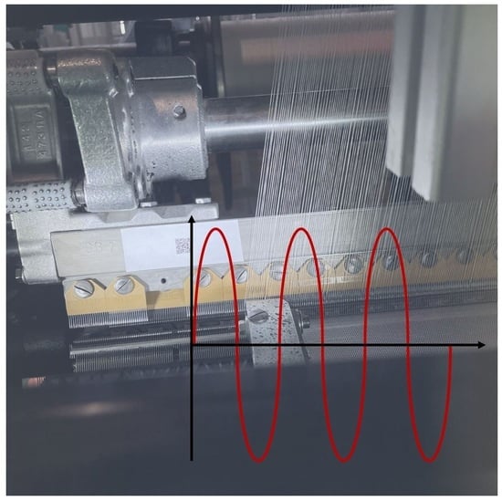
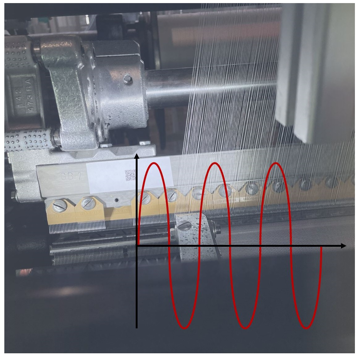
The high-performance warp knitting process is characterized by very high production speeds compared to weaving and flat knitting, with correspondingly high main shaft speeds (up to 4400 rpm ≙ 73.3 courses per second). The warp yarns are continuously fed to ensure consistent high quality fabric production, whereas the knitted fabric is continuously drawn off. However, the yarn demand in the working area is strongly discontinuous (also negative) due to the spatial oscillation of the guide bars around the needles and the formation of yarn loops, and a pronounced non-stationarity arises. The knitting process at the working position consists of six complex individual movements that generate extremely short-term dynamic force effects on the yarn in all three spatial directions. This, combined with the natural vibration of moving machine parts, results in highly variable yarn speeds and, therefore, high accelerations of up to 500 m/s2. In addition, longitudinal and transverse vibrations occur in the yarn path, with varying degrees of intensity. The vibration characteristics are highly material-dependent and base on the fineness, yarn tension, stiffness, bending stiffness, and damping properties, as well as the free path length and the vibration-inducing forces on the limiting knitting and yarn-guiding elements. The characteristics of the natural oscillations of the moving machine elements are directly influenced by the machine speed (main shaft speed) and, under unfavorable machine conditions, can lead to considerable resonance amplification and phase shifts between the knitting process and the yarn delivery. The first natural vibrations of the system (machine elements plus yarn) occur at a machine speed of 1800 rpm, and the processing of yarns with low elastic elongation becomes difficult. At machine speeds above 3000 rpm, the natural vibrations of the system are so pronounced that only elastane yarns can be processed effectively [17,20].
Liu et al. [7] dealt with the analysis of yarn tension fluctuations in the chain warp knitting process. In this paper, a mathematical calculation of the yarn demand is made based on the motion of the laying bars and needles, assuming simple linear motions. The yarn is described as linearly elastic and massless, similar to de Weldige [20]. However, the damping properties or transverse vibrations of the yarn are not taken into account. In addition, the yarn tension element, which compensates for the different yarn length differences in the chain warp knitting process, is assumed to be rigid with a fixed arrangement. Thus, the interaction between loop formation, yarn, and tension element is not taken into account. This leads to only a very rough description of the yarn path on chain warp-knitting machines. Moreover, the influence of binding variations in chain warp knitting (especially fringe, jersey to atlas) formed by different offset positions during the laying phase of the machines and the resulting varying yarn–yarn and yarn–knitting process interactions are not taken into account in this highly simplified approach.
In summary, it can be stated that simulations for textile processes are complex due to the large number of parameters and the complex yarn behaviors [21], and there is currently no model-based description of warp knitting processes that takes into account relevant dynamic parameters of the yarn run as well as moving machine elements in contact with the typically non-linear elastic yarn [22], such as transverse accelerations with resulting transverse vibrations and longitudinal vibrations, including associated damping phenomena and friction effects. This is particularly true for high-performance warp knitting, which has both significant economic importance due to the very high processing speeds and a very high potential for scientific knowledge regarding new speed-dependent material laws and dynamic interactions between the various components of the warp knitting process [20].
Validation of the simulation results describing this process is essential for a deeper understanding of the material and the process and provides the basis for deriving design mechanisms and control loops for the targeted homogenization of high yarn tensions and demand fluctuations. This enables higher warp knitting speeds, especially with low-stretch high-performance fibers, as well as higher productivity in general. There is, therefore, a great need for research in this area. A comprehensive simulation model also meets the need for digitalization. A digital twin for warp-knitting machines opens up new methods of product development. It can also improve existing products and production methods [5].
A key requirement for a successful simulation model is an understanding of the material model under vibration. Due to the highly anisotropic nature of yarn materials, it is also expected that there will be a difference between transversal and longitudinal oscillations. Longitudinal oscillations are mainly caused by the tensile forces generated by stitch formation and take-up. Transversal oscillations are caused by displacement during the laying phase and vibrations of the yarn guide elements. Considering the number of yarns in the warp-knitting process, these generate considerable forces. In order to determine the exact values in a simulation environment, a deep understanding of the damping behaviors of the yarn materials is required and, therefore, is a desirable topic of research. As a first step, this paper focuses on the damping behavior and viscoelastic properties in the longitudinal direction of the yarn.
2. Materials and Methods
2.1. Materials
The versatility of the warp knitting process leads to its utilization for many different markets and products, ranging from very fine and sensitive ones, like silk fabrics over cotton and polyester products for the fashion industry up to high strength reinforcement structures for fiber-reinforced products [23]. Therefore, the challenges are also diverse. Some materials may break due to high yarn demand fluctuations, whereas other high-performance fibers may also damage parts of the machine like needles and yarn-guiding elements if the process is not tailored to their properties.
To represent different use cases and material categories three different yarns were chosen for the research in this paper. They are often processed on warp knitting machines but are limited in their reachable production speeds due to their strengths and limited strains. One material that is important for many consumer products is polyester. In the present paper, the choice is made for two variants, a texturized one that is commonly used for fashion products and a high tenacity one that is more suitable for technical textiles. The other material of interest in this research is an aramid fiber as a representative for the high-performance fiber materials with their very limited strain values (Table 1).
2.2. Methods
A common method to determine the dynamic behavior of a material is dynamic mechanical analysis (DMA) [24,25]. It allows the determination of moduli, damping, and further viscoelastic characteristics of polymers. Generally, the experiment is performed by applying a oscillation on the material of interest. The resulting vibration profile of the sample is recorded by means of strain or force. This is repeated with different excitation frequencies either in different trials or through a ramp function. Repetition with varying temperatures is optional to gain further information on temperature dependency. The force can be axial or torsional [26].
There are two common approaches for a DMA: forced resonance and free resonance analysis. The forced resonance method requires a setup with rigid clamps that stimulate the sample with either a constant sinusoidal force or strain function. A matching sensor records the corresponding material reaction. The frequency increases in discrete steps or a continuous sweep. Under use of the material’s response, the phase shift δ between strain ε and stress σ is determined, and they are shown in the following equations:
and
with t as time, and ω as oscillation frequency. This allows for the frequency-dependent calculations of storage and loss moduli as real and imaginary parts of the Young’s modulus, with the Young’s modulus being calculated given by
The real part or storage modulus is calculated as
and imaginary part or loss modulus results in
The dissipation factor as a key indicator for the damping behavior of a material is defined as
For free resonance analysis, the samples were left to their own devices after an initial deflection and the following release [27]. In the following, evolving oscillation resembled the steady energy exchange between kinetic energy and potential energy. As there were also further momentums and tensions within the material, the vibrations dampened over time, and the sum of kinetic energy and potential energy reduced. This resulted in a decreasing amplitude over time. This course was recorded, was the basis for the calculation of damping coefficients, and was dependent on the material’s viscoelastic properties.
The present research chose the method of forced resonance with strain control. This choice was made as this procedure provided the possibility to test for the viscoelastic properties of the yarn materials with parameters that resembled the stress and strain conditions in the warp-knitting machine and process. A setup for this method can furthermore be designed to work with span lengths that are similar to the free yarn lengths along the path within the machine. As the available testing equipment cannot provide the necessary sample lengths, the choice for an individual test rig is made. The desired build needs to feature a unit that creates longitudinal oscillations with amplitudes of several mm at frequencies of up to 75 Hz. The created vibration needs to be precisely recorded. Most importantly, the force response of the material must be registered, but it is also recommended to measure the displacement of excitation unit for an accurate calculation of the applied strain.
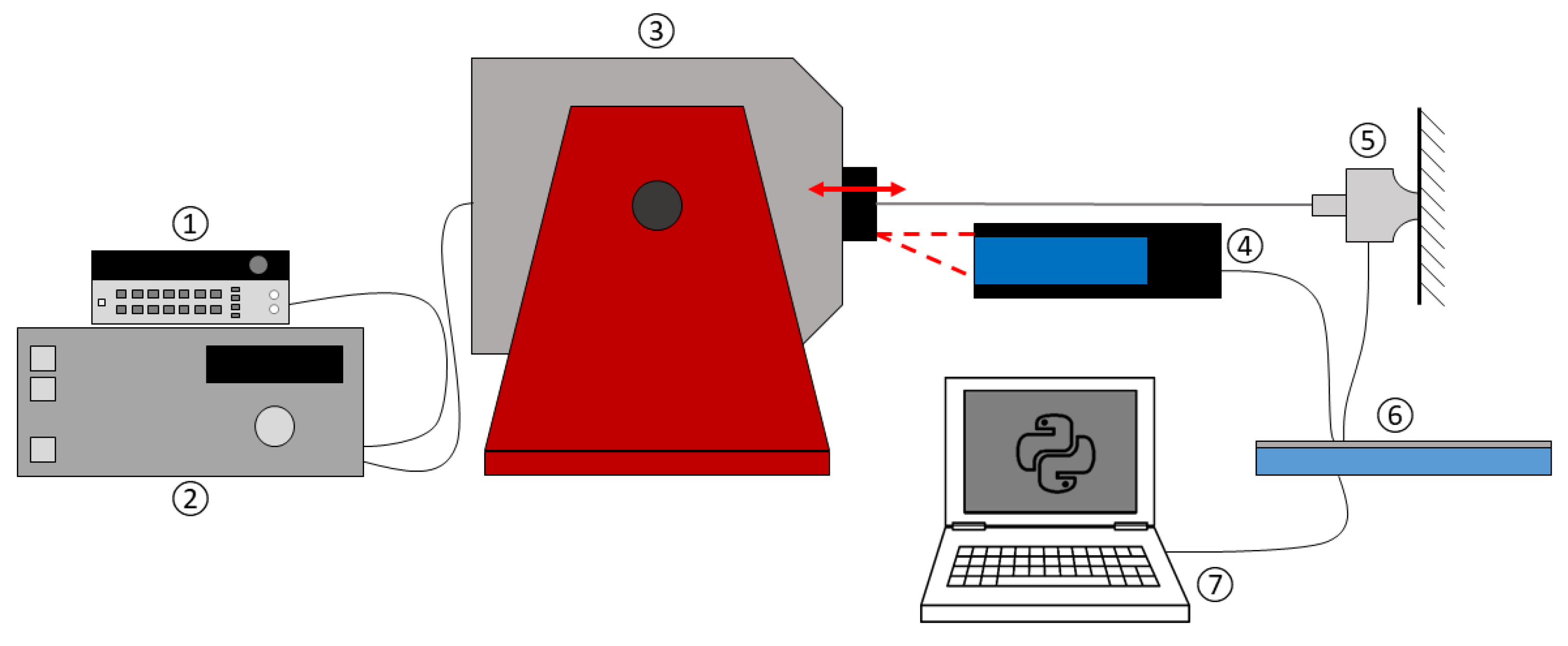
The setup (Figure 1) derived from the aforementioned conditions consisted of a permanent magnet shaker to apply an oscillation, a piezo force sensor to record the material’s response at high frequencies, and a single-point laser displacement sensor to determine the displacement of the shaker unit and, therefore, the strain of the yarn sample (Figure 2). The whole setup was placed on a granite table, which was intended to absorb any unintended vibrations in the setup.
To allow a fixation of the yarn samples that did limit the loss of strain and force through slip, a mold was created. With this mold, small end pieces were poured on the yarn sample ends. Challenging in this process were the capillary effects that led to a flow of epoxy into the yarn structure. To prevent this from distorting the material’s response to the excitation oscillation, the mold was designed to be very tight, and all of samples were checked for indicators of epoxy outside the end pieces. Using these end pieces, the samples were screwed to the adapter of the permanent magnet shaker with the piezo force sensor on the other end. The horizontal placement of the material of interest was chosen to minimize the effects of gravity on a vibration in the longitudinal yarn direction. Before the sample was placed, the permanent magnet shaker and piezo force sensor were best-possible horizontally and vertically aligned, so the created oscillations were solely longitudinal and closest possible to the yarn axis. The displacement sensor focused on the mounting adapter on the shaker to detect the amplitudes of displacement and, therefore, the strain of the sample. As the samples of yarn were fixed length, due to the molded the end pieces, the piezo force sensor was adjustable in the yarn direction to allow the adjustment of a defined pre-strain, like it was prevailing on a warp-knitting machine.
The piezo force sensor U9C by HBM, Germany, was selected for its high responsiveness. It allowed a force limit of 50 N and featured an accuracy class of 0.2, meaning a maximum measurement deviation of 0.2%. The force limit appeared to be sufficient based on the force values measured on a warp-knitting machine, which rarely exceeded 20 N for a single thread. The displacement sensor optoNCDT 1700–20 by Micro Epsilon, Germany, had a measurement range of 20 mm. The signal of the piezo force sensor and the laser displacement sensor were recorded using the multifunction data acquisition device USB-6003 from National Instruments. The internal buffer storage was read with a Python script that also performed data conversion and saving. The permanent magnet shaker LDS V455 from Hottinger Brüel & Kjaer GmbH, Germany, was primarily chosen for its high displacement to resemble conditions in a warp-knitting machine. The required sinusoidal signal was created by a frequency generator 33120A from Hewlett Packard. It was capable of creating 10 different waveforms, with sine, square, triangle, and ramp waveform functions, among others, with varying amplitudes and frequencies. The possible frequency for a sine waveform function ranged from 100 µHz to 15 MHz with an output amplitude range from 100 mVpp to 20 Vpp for an open-circuit output termination. Furthermore, the option of modulating a burst or sweep was also given. The created signal was then amplified by the repeater of the permanent magnet shaker.
The test parameters for strain control were derived from strain measurements on a warp-knitting machine Copcentra 3K from Karl Meyer Textilmaschinenfabrik GmbH, Germany (formerly LIBA Maschinenfabrik GmbH, Naila, Germany). Depending on the processed material, the machine ran up to 4400 rpm. This was a theoretical value that was unreachable for the majority of yarn materials. For the present high-performance fiber material, the testing parameters were derived from the strain measurements, except for the parameters at speeds higher than 2400 rpm that are estimated.
3. Results
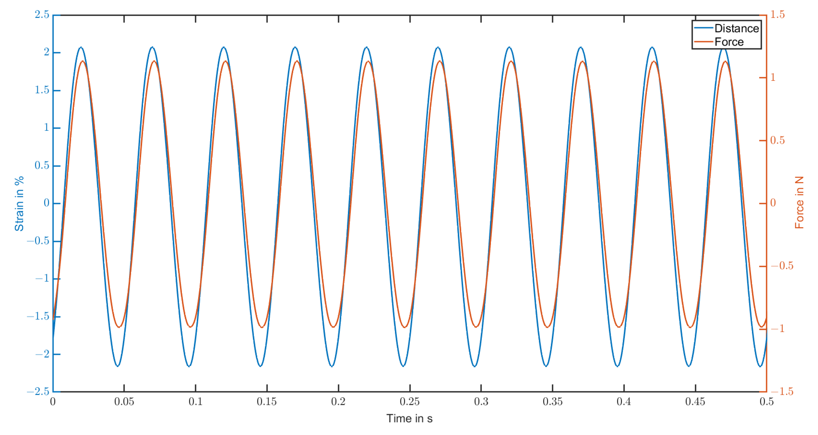
The displacement of the shaker and the force induced to the yarn samples were determined dependent on time. Using the pre-strain applied before start of the trials, initial strain and initial stress were calculated. In Figure 3, the development of both values was exemplary shown for an aramid sample at a frequency of 20 Hz. The shown behavior was observable for all tested materials, and only the amplitudes differed. For each material, five samples were investigated, with three test runs performed on each of them.
The frequency of 20 Hz represented the lower end of common production speeds for sensitive materials (1200 rpm). The materials in this paper were tested for excitation frequencies of up to 50 Hz (3000 rpm), which exceeded the maximum production speeds for most materials in addition to highly elastic yarns. It was apparent that a uniform sinusoidal function evolved. It was proposed that no resonance effects appeared, and the oscillation was solely a result of the excitation. Verifying this statement, longer test runs were performed on all materials. With periods of up to five minutes under constant excitations, the amplitudes of the samples remained on a steady level. Due to the constant periodic time of the forced vibration, a constant phase shift was considered. To calculate the dimension of the phase shift between the recorded distance and force function, the zero points of both functions were determined by linear approximation between values around the change in sign.
As the process ran, strain-controlled, all-stress zero points earlier than the first strain zero points were neglected. The difference between a strain and a stress zero point was defined as Δt, according to the following formula:
The phase shift (rad) between distance and force was calculated using the runtime difference (see Table 2) and the excitation frequency f. Based on the phase shift, the dissipation factor was determined using Equation (1). As this was a key indicator for the damping behavior of the materials, it could be used to create frequency dependent material models for the simulation of the warp knitting process. Jeddi et al. [28] did not test pure polyester but polyester cotton blends. The dissipation factor estimated based on their diagram for appeared in a magnitude similar to the present work. It was between 0.10 and 0.14 at 5 Hz, dependent on the blend and fatigue, which indicated valid results, as they are presented here.
4. Discussion
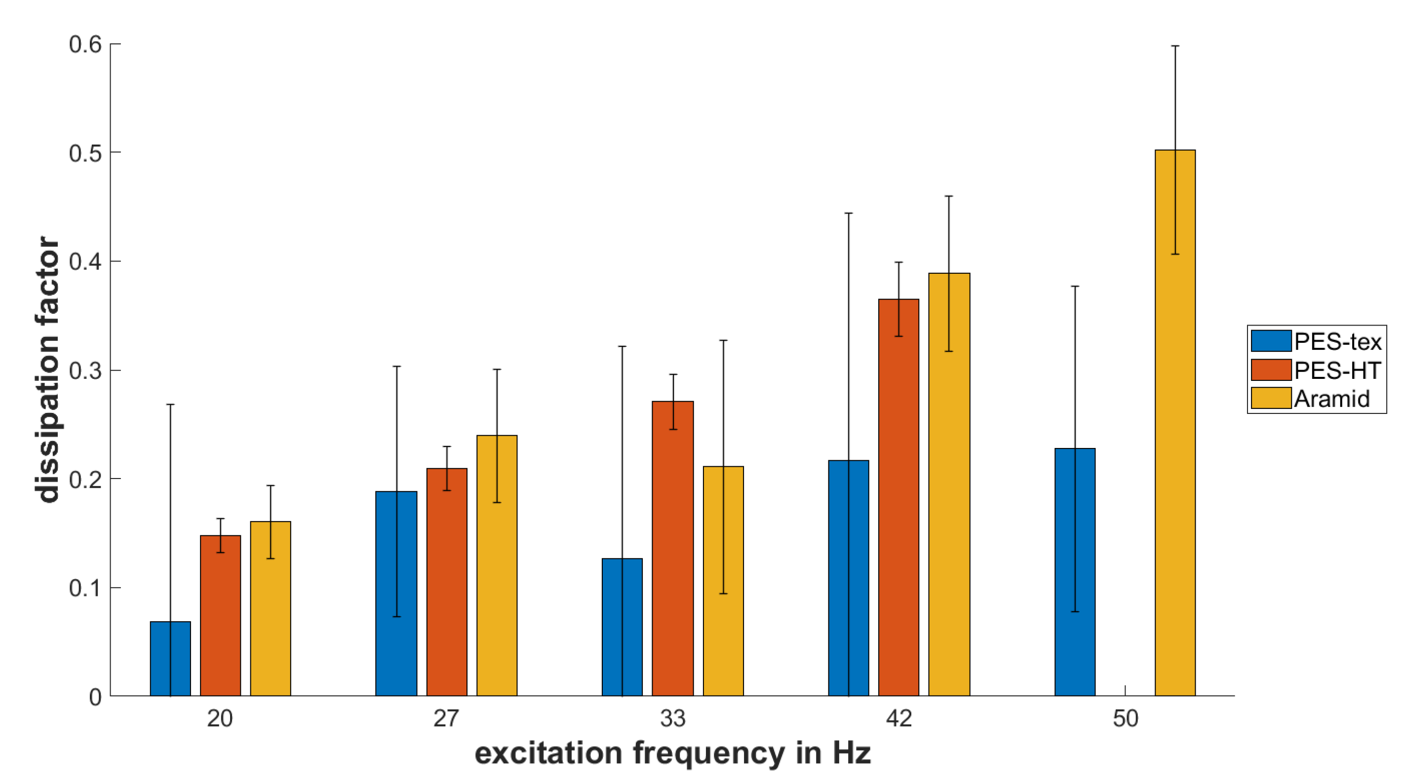
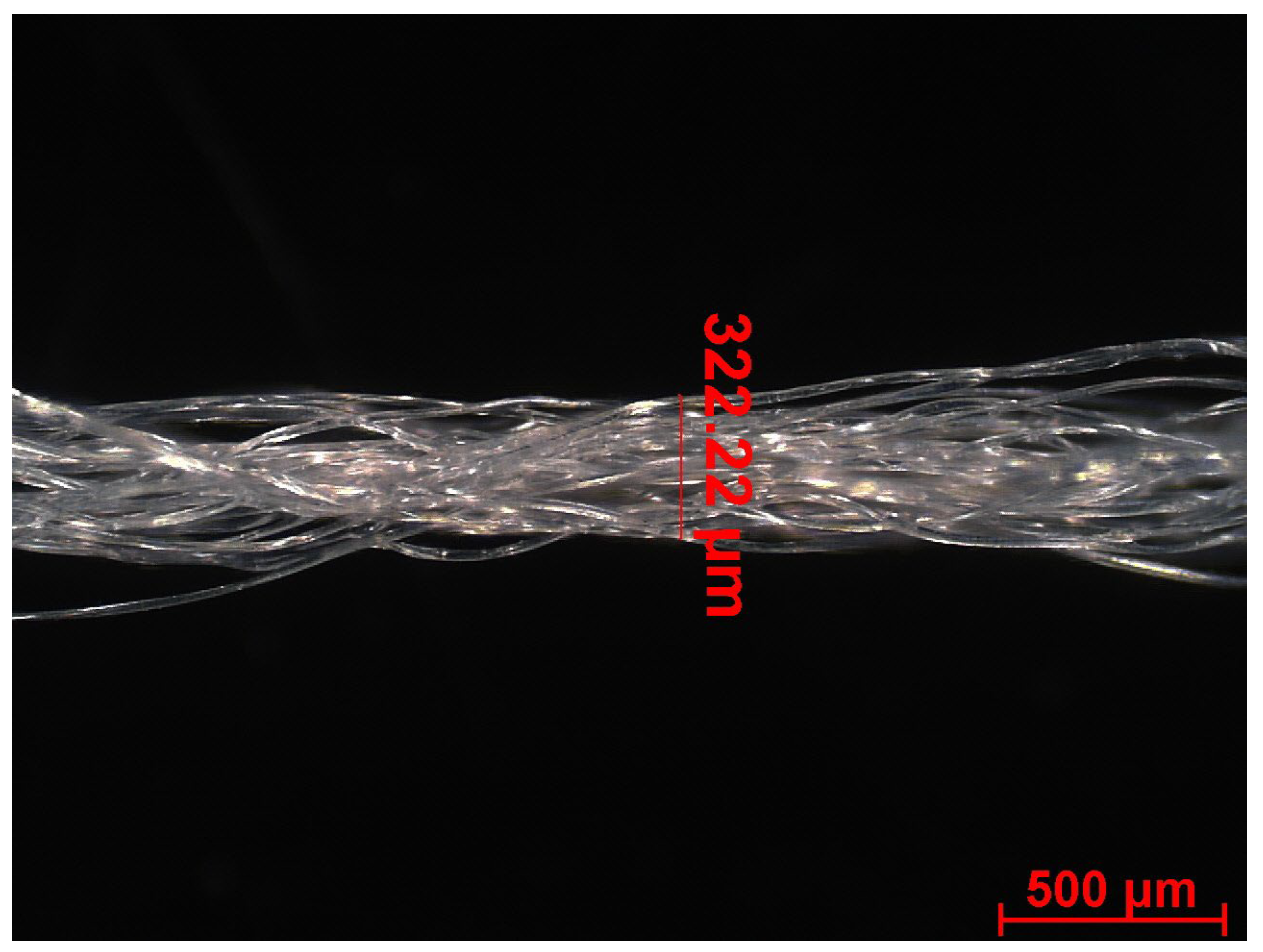
In Figure 4, the calculated dissipation factors are displayed. They represent the mean value of all samples tested. It is apparent that the dissipation factor is highly frequency dependent. With increasing frequency, the dissipation factor rises as well. Consequently, the rising loss modulus indicates that the amount of energy that converts to thermal energy through friction and similar processes increases. While aramid and HT-PES are relatively close to each other and show similar behaviors, the values for PES-tex appear lower but not significantly different from the other two materials, due to the high standard deviation (Table 3). Reasons for this may be various, but are mainly reasoned in its structure. All three materials consisted of multifilaments, but the orientation for PES-tex was much lower, as it was texturized for a nicer feel in fashion products (Figure 5). A lower dissipation factor corresponded with a higher share of the storage modulus, which represented the elastic component of the material’s behavior. Considering that PES-tex allowed for an elastic strain multiple times higher than HT-PES and aramid did, this may have been the reason for the lower dissipation factor. The loose orientation may have also been the cause for the high standard deviation, as, with the chosen clamping setup, the percentage of loose and tensioned strains within the multifilament varied with every sample.
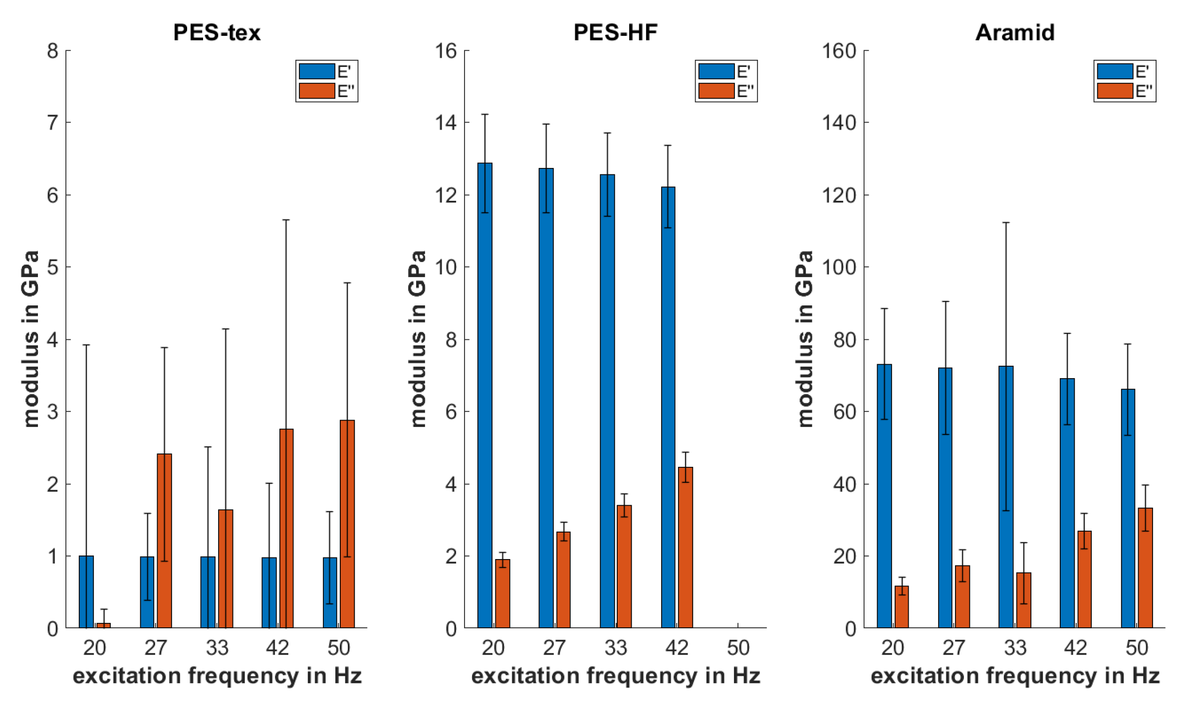
The change in the dissipation factor resembled a shift in the percentages between loss and storage modulus as part of the Young’s modulus. As evident from the data for the dissipation factor and Equations (4) and (5), the storage modulus decreased with rising frequency, whereas the loss modulus decreased (Figure 6). If Equation (6) is also considered, the correlation between the moduli is given by:
It is important to note that the ascertained values only applied to the longitudinal yarn properties. Due to the highly anisotropic behaviors of the yarns, the transversal properties will most probably differ and require a different setup to determine. Furthermore, the parameters may differ, as movement in a transversal direction during warp knitting mainly depends on the chosen binding and corresponding swing motion of the laying bar.
5. Conclusions
The present work presented an approach for the dynamic mechanical testing of yarns. The collected force and strain data allowed for a determination of the yarns’ viscoelastic properties, specifically their phase shifts. Based on this, the dissipation factor was calculated as key indicator for the damping behavior. The results showed that it was dependent on the excitation frequency, meaning the machine speed. It rose with higher speeds, indicating that the share of the loss modulus rose, resulting in a higher conversion of kinetic energy to thermal energy and, therefore, loss. This behavior was expected and suggested that the chosen test setup proved suitable for dynamic mechanical analysis trials. Nevertheless, it showed some challenges with loosely texturized yarns like the tested texturized polyester yarn. Here, it was not guaranteed that all strains of the yarn were equally tensioned, leading to higher standard deviation. This material also showed lower dissipation factors, indicating more elastic behavior compared to the other two yarns.
The results allowed for the creation of a more detailed yarn model as well as a representation of the stitch-formation process in simulation environments. In addition to the static properties, like the Young’s modulus, the present research allowed for the definition of dynamic viscoelastic properties that were of high relevance for simulations at production speed. Combined with earlier results of the same project [15,29,30], the present findings allowed for the detailed simulation of the following processes that were part of the warp knitting:
Unwinding and winding of yarns at typical processing speeds, including the corresponding tensions arising from the winding;
Yarn path over moving yarn-guiding elements with excitation of longitudinal and transverse yarn vibrations, including the examination of the complete relevant frequency spectrum;
Hooking and unhooking of yarns in guide elements;
Yarn contact and sliding of yarns on each other;
Core model of the interaction between loop formation and yarn guiding;
Overall model of a high-performance warp-knitting machine with yarn path and stitch-formation process.
In addition to the digital, resource efficient optimization of the warp knitting process, this also allowed for the development of actively controlled yarn tension compensation mechanisms for single threads. Actively controlled yarn management would also allow higher production speeds for low strain, high-performance materials like aramid, glass, and carbon fibers. It will, furthermore, improve the product’s quality, especially regarding defects or inconsistencies that are created during the acceleration or deceleration of the warp-knitting machine. The typical boundary effects in warp-knitting on the edge of the produced fabrics may also be reduced effective yarn demand management. With these product quality improvements, sustainability is also improved, as less waste is created during cutting processes, as more of the material’s width can be used, and the number of defects is lower. A more uniform quality also facilitates production steps later on, like dying processes.
While the present paper covered the material behaviors for the dominant yarn delivery direction oscillations in a longitudinal direction, the influence of temperature should not be neglected for a comprehensive determination of viscoelastic properties. The temperature influence was not considered in the present paper, as warp-knitting machines usually run in a constant-temperature environment. The transversal oscillations arose from moving yarn-guiding elements, whether they were actively controlled or elastically mounted, e.g., with spandex elements for yarn demand compensation and the offset movement in multiple directions of the laying bar during the stitch-formation process. This means that they were highly dependent on the chosen binding for the textile product. The material behavior is expected to differ in the transversal direction due to the anisotropic characteristics of yarns, meaning that the damping properties for these transversal-induced vibrations may differ. The determination of the viscoelastic and damping properties is highly desirable to enhance the simulation model and get a comprehensive representation of the yarn’s behavior. The transversal direction cannot be neglected, as the swing motion of the laying bar induced high acceleration on the yarn. As the direction of excitation is completely different, a new test build is required. For this purpose, the procedure for the dynamic mechanical analysis can also be reconsidered if the free resonance methods serves better for the new target. In order to cover this topic, intense research work needs to be conducted and will be presented in future publications.
Author Contributions
Conceptualization, K.K. and M.B. (Mathis Bruns); methodology, K.K.; software, K.K. and A.N.; validation, K.K., A.N. and M.B. (Michael Beitelschmidt); writing—original draft preparation, K.K.; writing—review and editing, A.N., M.B. (Michael Beitelschmidt) and C.C.; supervision, C.C. All authors have read and agreed to the published version of the manuscript.
Funding
This research was funded by the Deutsche Forschungsgemeinschaft (DFG, German Research Foundation), grant number CH 174/44-1.
Data Availability Statement
Data are available from the authors upon reasonable request.
Acknowledgments
The financial support by the Deutsche Forschungsgemeinschaft is gratefully acknowledged.
Conflicts of Interest
The authors declare no conflict of interest. The funders had no role in the design of the study; in the collection, analyses, or interpretation of data; in the writing of the manuscript; or in the decision to publish the results.
Denninger, D.; Berger, M. Mechanischer Fadenlängenausgleich zur optimalen Handhabung von Flechtmaterialien. In Proceedings of the 14. Chemnitzer Textiltechnik Tagung, Chemnitz, Germany, 13–14 May 2014. [Google Scholar]
Pohlen, V.; Schnabel, A.; Neumann, F.; Gries, T. Optimisation of the warp yarn tension on a warp knitting machine. AUTEX Res. J.2012, 2, 29–33. [Google Scholar] [CrossRef]
Duru, S.C.; Candan, C.; Mugan, A. Effect of yarn, machine and knitting process parameters on the dynamics of the circular knitting needle. Text. Res. J.2015, 6, 568–589. [Google Scholar] [CrossRef]
Liu, X.; Miao, X. Analysis of yarn tension based on yarn demand variation on a tricot knitting machine. Text. Res. J.2017, 4, 487–497. [Google Scholar] [CrossRef]
Su, L.; Meng, Z.; Sun, Y.; Ge, X. Reliability-based optimization design of the latch needle mechanism in double-needle warp knitting machine. J. Braz. Soc. Mech. Sci. Eng.2018, 4, 205. [Google Scholar] [CrossRef]
Bunsell, A.R. Handbook of Tensile Properties of Textile and Technical Fibres; Woodhead Publishing: Sawston, UK, 2009. [Google Scholar]
Zubair, M.; Neckar, B.; Eldeeb, M.; Baig, G.A. Tensile behavior of staple fiber yarns, part IV: Experimental verification of predicted stress—Strain curves. J. Text. Inst.2017, 8, 1291–1296. [Google Scholar] [CrossRef]
Dietz, W. Polyester fiber spinning analyzed with multimode Phan Thien-Tanner model. J. Non-Newton. Fluid Mech.2015, 217, 37–48. [Google Scholar] [CrossRef]
Finckh, H. Hochgeschwindigkeits-Zugprüfung an technischen Garnen. In Proceedings of the Zwick/Roell Textil Symposium, Ulm, Germany, 27 January 2011. [Google Scholar]
Weiß-Quasdorf, M.; Lützkendorf, M.; Gombic, L.; Hauspurg, C. Versagensverhalten dynamisch belasteter Hochleistungsgarne bei Hochgeschwindig-keitsbelastung. In Proceedings of the 51st Man-Made Fibers Congress, Dornbirn, Austria, 21 September 2012. [Google Scholar]
Bahners, T.; Schloßer, U.; Gutmann, J. Untersuchung des Visko-Elastischen Verhaltens Technischer Garne bei Kurzzeitbean-Spruchungen mit Hoher Dehnungsgeschwindigkeit (AiF 15925 BG); Deutsches Textilforschungszentrum Nord-West e.V.: Krefeld, Germany, 2011. [Google Scholar]
Franz, C.; Häntzsche, E.; Hoffmann, G.; Nocke, A.; Cherif, C. Simulation of the stich formation process and modelling of the yarn movement in high performance tricot knitting machines. In Proceedings of the AUTEX2019—19th World Textile Conference on Textiles at the Crossroads, Ghent, Belgium, 11–15 June 2019. [Google Scholar]
Metzkes, K.; Schmidt, R.; Märtin, J.; Hoffmann, G.; Cherif, C. Simulation of the yarn transportation dynamics in a warp knitting machine. Text. Res. J.2013, 12, 1251–1262. [Google Scholar] [CrossRef]
Ünal, A. Analyse und Simulation des Fadenlängenausgleichs an Kettenwirkmaschinen für die Optimale Konstruktion von Fadenspanneinrichtungen. In Dresdner Forschungen/Maschinenwesen; Technische Universität Dresden: Dresden, Germany, 2003. [Google Scholar]
Koo, Y.-S. Yarn Tension Variation on the Needle During the Knitting Process. Text. Res. J.2004, 4, 314–317. [Google Scholar] [CrossRef]
de Vasconcelos, F.B.; Marcicano, J.P.P.; Sanches, R.A. Influence of yarn tension variations before the positive feed on the characteristics of knitted fabrics. Text. Res. J.2015, 17, 1864–1871. [Google Scholar] [CrossRef]
Märtin, J. Analyse, Simulation und Weiterentwicklung des Materialtransportes in Hochleistungskettenwirkautomaten zur Steigerung der Technologischen Leistungsparameter; ITM: Dresden, Germany, 2012. [Google Scholar]
Veit, D. Simulation in Textile Technology; Woodhead Publishing: Oxford, UK, 2012. [Google Scholar]
Ceravolo, R.; de Marchi, A.; Pinotti, E.; Surace, C.; Zanotti Fragonara, L. A New Testing Machine for the Dynamic Characterization of High Strength Low Damping Fiber Materials. Exp. Mech.2017, 1, 65–74. [Google Scholar] [CrossRef]
Ballou, J.W.; Smith, J.C. Dynamic Measurements of Polymer Physical Properties. J. Appl. Phys.1949, 6, 493–502. [Google Scholar] [CrossRef]
Tsai, C.L.; Daniel, I.M.; Lou, J.J. Measurement of longitudinal shear modulus of single fibers by means of a torsional pendulum. Int. SAMPE Symp. Exhib. (Proc.)1993, 38, 1861–1868. [Google Scholar]
Jeddi, A.A.; Nosraty, H.; Taheri Otaghsara, M.R.; Karimi, M. A Comparative Study of the Tensile Fatigue Behavior of Cotton—Polyester Blended Yarn by Cyclic Loading. J. Elastomers Plast.2007, 2, 165–179. [Google Scholar] [CrossRef]
Bruns, M.; Krentzien, M.; Beitelschmidt, M.; Cherif, C. Experimental Investigations on the Effect of Yarn Speed and Wrap Angle on Yarn-Solid and Yarn-Yarn Friction using Warp Knitting Machines. Mater. Sci. Forum2022, 1079, 115–126. [Google Scholar] [CrossRef]
Golla, A.; Franz, C.; Haentzsche, E.; Hoffmann, G.; Sennewald, C.; Cherif, C. Geometrical modeling of yarn motion and analysis of yarn tension during stitch formation process in warp knitting machines. Text. Res. J.2023, 93, 004051752311661. [Google Scholar] [CrossRef]
Figure 1.
Layout of the test setup: ➀ sine frequency generator, ➁ signal amplifier, ➂ permanent magnet shaker, ➃ point laser displacement sensor, ➄ piezo force sensor, ➅ multifunction DAQ device, and ➆ computer with python script.
Figure 1.
Layout of the test setup: ➀ sine frequency generator, ➁ signal amplifier, ➂ permanent magnet shaker, ➃ point laser displacement sensor, ➄ piezo force sensor, ➅ multifunction DAQ device, and ➆ computer with python script.
Figure 2.
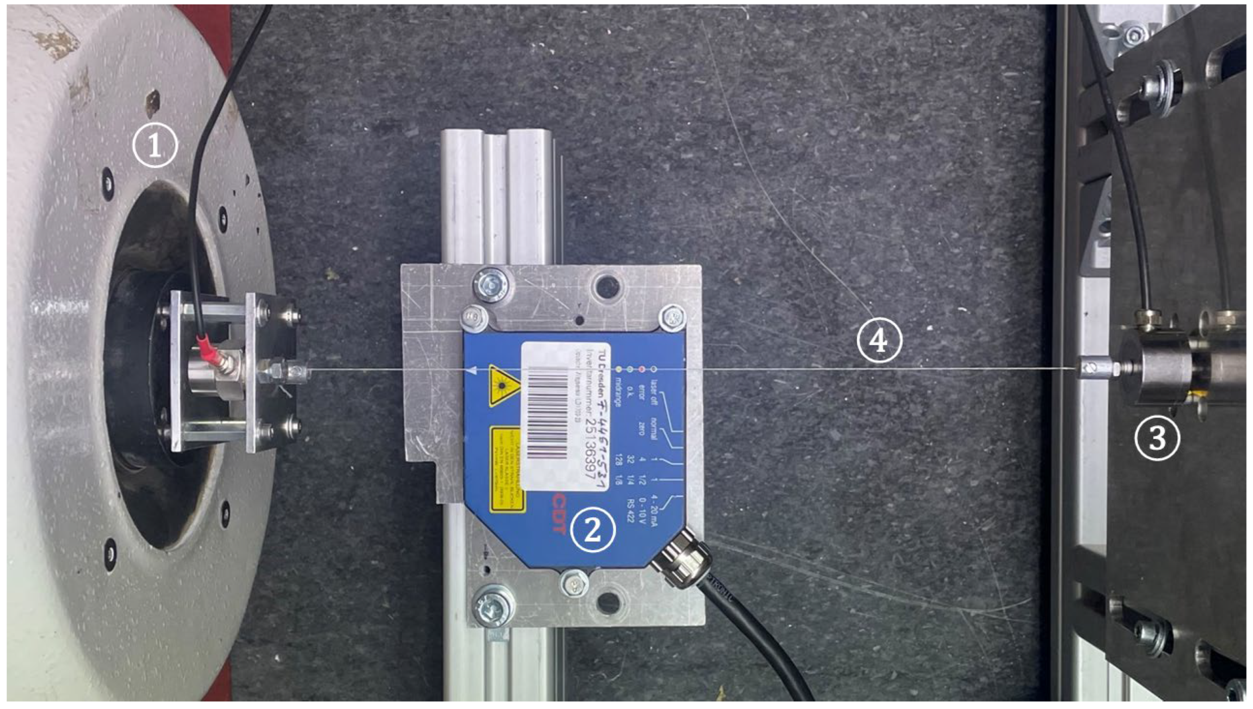
Picture of the testing rig with ➀ permanent magnet shaker, ➁ point laser displacement sensor, ➂ piezo force sensor, and ➃ yarn sample.
Figure 2.
Picture of the testing rig with ➀ permanent magnet shaker, ➁ point laser displacement sensor, ➂ piezo force sensor, and ➃ yarn sample.
Figure 3.
The progress of strain and force of an aramid sample under a constant excitation frequency of 20 Hz.
Figure 3.
The progress of strain and force of an aramid sample under a constant excitation frequency of 20 Hz.
Figure 4.
Comparison of the dissipation factor at different frequencies for the tested materials.
Figure 4.
Comparison of the dissipation factor at different frequencies for the tested materials.
Figure 5.
Microscopy picture of PES-tex showing its loose orientation in tension free state.
Figure 5.
Microscopy picture of PES-tex showing its loose orientation in tension free state.
Figure 6.
Development of the loss and storage modulus of the different materials over the frequency increase.
Figure 6.
Development of the loss and storage modulus of the different materials over the frequency increase.
Table 1.
Overview of reviewed yarn materials.
Table 1.
Overview of reviewed yarn materials.
Material
Manufacturer
Yarn Count (dtex)
Yarn Diameter (µm)
Young’s Modulus (GPa)
HT-PES
PHP-Fibers GmbH, Ger
140
232
13
PES-tex
TWD fibres, Ger
179
185
1
Aramid
Teijin Aramid BV, Nld
225
438
74
Table 2.
The runtime differences for all materials.
Table 2.
The runtime differences for all materials.
Runtime Difference Δt in ms
Frequency
PES-HT
PES-Tex
Aramid
Hz
Mean
St. Dev.
Mean
St. Dev.
Mean
St. Dev.
20
1.537
0.1240
0.166
0.0840
1.550
0.2735
27
1.976
0.1025
0.236
0.1515
2.537
0.4430
33
2.643
0.2330
0.284
0.1590
3.182
0.4210
42
3.414
0.2120
0.338
0.1655
3.707
0.6175
50
-
-
0.433
0.2010
4.645
0.7735
Table 3.
Dissipation factor of the tested materials at different excitation frequencies.
Table 3.
Dissipation factor of the tested materials at different excitation frequencies.
Dissipation Factor
Frequency
PES-HT
PES-Tex
Aramid
(Hz)
Mean
St. Dev.
Mean
St. Dev.
Mean
St. Dev.
20
0.1473
0.0165
0.0685
0.2002
0.1604
0.0336
27
0.2095
0.0201
0.1883
0.1153
0.2393
0.0613
33
0.2706
0.0250
0.1269
0.1946
0.2111
0.1165
42
0.3647
0.0341
0.2169
0.2275
0.3886
0.0715
50
-
-
0.2274
0.1496
0.5021
0.0960
Disclaimer/Publisher’s Note: The statements, opinions and data contained in all publications are solely those of the individual author(s) and contributor(s) and not of MDPI and/or the editor(s). MDPI and/or the editor(s) disclaim responsibility for any injury to people or property resulting from any ideas, methods, instructions or products referred to in the content.
Kopelmann, K.; Bruns, M.; Nocke, A.; Beitelschmidt, M.; Cherif, C.
Characterization of the Viscoelastic Properties of Yarn Materials: Dynamic Mechanical Analysis in Longitudinal Direction. Textiles2023, 3, 307-318.
https://doi.org/10.3390/textiles3030021
AMA Style
Kopelmann K, Bruns M, Nocke A, Beitelschmidt M, Cherif C.
Characterization of the Viscoelastic Properties of Yarn Materials: Dynamic Mechanical Analysis in Longitudinal Direction. Textiles. 2023; 3(3):307-318.
https://doi.org/10.3390/textiles3030021
Chicago/Turabian Style
Kopelmann, Karl, Mathis Bruns, Andreas Nocke, Michael Beitelschmidt, and Chokri Cherif.
2023. "Characterization of the Viscoelastic Properties of Yarn Materials: Dynamic Mechanical Analysis in Longitudinal Direction" Textiles 3, no. 3: 307-318.
https://doi.org/10.3390/textiles3030021
APA Style
Kopelmann, K., Bruns, M., Nocke, A., Beitelschmidt, M., & Cherif, C.
(2023). Characterization of the Viscoelastic Properties of Yarn Materials: Dynamic Mechanical Analysis in Longitudinal Direction. Textiles, 3(3), 307-318.
https://doi.org/10.3390/textiles3030021
Article Metrics
No
No
Article Access Statistics
For more information on the journal statistics, click here.
Multiple requests from the same IP address are counted as one view.
Kopelmann, K.; Bruns, M.; Nocke, A.; Beitelschmidt, M.; Cherif, C.
Characterization of the Viscoelastic Properties of Yarn Materials: Dynamic Mechanical Analysis in Longitudinal Direction. Textiles2023, 3, 307-318.
https://doi.org/10.3390/textiles3030021
AMA Style
Kopelmann K, Bruns M, Nocke A, Beitelschmidt M, Cherif C.
Characterization of the Viscoelastic Properties of Yarn Materials: Dynamic Mechanical Analysis in Longitudinal Direction. Textiles. 2023; 3(3):307-318.
https://doi.org/10.3390/textiles3030021
Chicago/Turabian Style
Kopelmann, Karl, Mathis Bruns, Andreas Nocke, Michael Beitelschmidt, and Chokri Cherif.
2023. "Characterization of the Viscoelastic Properties of Yarn Materials: Dynamic Mechanical Analysis in Longitudinal Direction" Textiles 3, no. 3: 307-318.
https://doi.org/10.3390/textiles3030021
APA Style
Kopelmann, K., Bruns, M., Nocke, A., Beitelschmidt, M., & Cherif, C.
(2023). Characterization of the Viscoelastic Properties of Yarn Materials: Dynamic Mechanical Analysis in Longitudinal Direction. Textiles, 3(3), 307-318.
https://doi.org/10.3390/textiles3030021


