Article

The Influence of Several Carbon Fiber Architecture on the Drapability Effect

by
Yuri Pereira Chuves
1,*,
Midori Pitanga
1,
Inga Grether
2,
Maria Odila Cioffi
1 and
Francisco Monticeli
3,*
1
Department of Materials and Technology, São Paulo State University, Guaratinguetá, São Paulo 12516-410, Brazil
2
Department of Engineering, Albstadt-Sigmaringen University, 72488 Albstadt, Germany
3
Department of Aeronautical Engineering, Technological Institute of Aeronautics (ITA), São José dos Campos 12228-900, Brazil
*
Authors to whom correspondence should be addressed.
Textiles 2022, 2(3), 486-498; https://doi.org/10.3390/textiles2030027
Submission received: 29 July 2022 / Revised: 25 August 2022 / Accepted: 30 August 2022 / Published: 5 September 2022
(This article belongs to the Special Issue Fibrous Materials (Textiles) for Functional Applications II)

Abstract

:
The growth of the aeronautical sector leads to the growth of polymer composites application, creating new demand for components applications in complex dimensions and shapes. Regarding different methods of draping 2D fabric into a 3D format, the concern is to keep the fabric properties and characteristics, since fiber orientation is modified after draping. For that purpose, this study aims to evaluate the drapability capacity of 2D dry fibrous fabrics (plain, twill, satin, non-crimp-fabric 0/90, and ±45) into a complex geometry, i.e., spherical indent. The energy required to drape fabric is composed of fabric deformation mechanisms (shear and bending), which were used together with microscopic deformation analysis to determine the appropriate fabric architectures with the highest malleability. Both NCF fabrics presented high energy and roughness on the fabric surface due to the folding effect of stitching. On the other hand, plain and twill weave fabrics required lower energy to drape but demonstrated higher fiber misalignment and deformation. The satin warp/weft relation favored shear and bending mechanisms, presenting better uniformity in load distribution, symmetry on drape capability, lower deformation degree, and lower fiber misalignment. Despite the intermediate load and energy required for drape, ANOVA and optimization methods confirmed that satin fabric showed better malleability behavior for complex geometries applications.

Graphical Abstract

1. Introduction

The aeronautics sector is interested in polymer composites reinforced with continuous fiber due to weight decrease, high mechanical stiffness, and being used as an alternative lightweight material to fuel economy [1,2,3,4]. With the expansion of composites in different components associated with the evolution of processing techniques, the necessity for manufactured modeling in complex geometries arose [5,6]. Concerning the conventional composite manufacturing process, industrial sectors have required a different way to former 2D fabric in a three-dimensional format, keeping the fabric properties and characteristics regarding the fiber orientation variance [6,7,8]. Composite processing techniques with complex geometry are mostly press-forming (presents a pressure force to deform the material), thermoforming (combination of pressure and temperature), and hand lay-up due to significant cost/benefit relation [9,10]. All these techniques are based on the shape and deform reinforcement pre-impregnated to obtain the final composite structure [11,12,13,14].
An important factor that could help conventional composite manufacturing is fabric drapability, which consists of dry fabric molding in the specific geometry of the final component before matrix addition [15,16]. Drapability is the proportion in which the fabric can drape under a predetermined format. The form capacity of fabric architecture influences the final composite quality, and defect formation could be detrimental to mechanical properties [15,17,18]. The main factors that affect drapability are fabric type and structure, amount of fiber yarns, weight, fabric thickness, and shear behavior [15,17,19]. The fabric warp/weft relation variation directly influences mechanical properties, including stiffness, crease recovery, and drapability [20,21]. Concerning previous characteristics, composite mechanical properties are mainly ruled by fiber orientation and amount [22,23,24]. In other words, every angular misalignment between warp and weft yarns could damage the composite mechanical behavior after fabric draping. Considering the challenge of forming fabrics in 3D shape, researchers are looking for different methods to evaluate the fabric drape [22,25,26]. Although drapability can be considered a subjective characteristic, the measurement of drapability response parameters can be used to quantify and precisely characterize this behavior [14,27].
Shear movement, known as the trellis-effect, occurs during inter-plane shear when fabric yarns rotate about their crossover points (warp and weft yarns) until a locking angle. Other mechanisms during fabric drapability are stretching, straining and shifting, fiber shear, and fiber breakage, reducing material mechanical properties [21,28].
Recent research investigated drapability with a specific approach. Omeroglu et al. [12] investigated round and trilobal full/hollow fabric drapability for plain and twill weave architecture. As a result, the drapability of the fabrics produced from hollow fibers was lower than those produced from full fibers, and plain fabrics had lower drapability than twill fabrics. Yarn’s high intersection points and low movement capability in plain weave led to a denser fabric unit structure. Allaoui et al. [22] developed a device to analyze double-curved composite part drapability. It has been shown that a tetrahedral shape used for corner brackets can be formed by punch and matrix without wrinkles in the helpful part. However, results were attributed to a specific interlock fabric suitable for forming that needs large shear angles. Their main contribution was to test the capability to simulate wrinkling development. Meanwhile, Hineno et al. [29] evaluated the drapability of sheets with five carbon plain weave layers impregnated with a heated thermoplastic resin. Results indicated that fiber deformation differs depending on the relationship between the fiber direction and the corner direction on the matrix, with visual analysis proving those achievements.
With the growth of prepreg or semipreg reinforced laminates in industrial sectors, the search for 3D fabric forming methods has been affected. Conformation in complex geometry can cause damage to the laminate structure, reducing the load for which the component was designed [30,31]. Hassan et al. [32] indicate that several defects could be performed during assessments of complex shapes, such as thickness nonuniformity, inter- or intralaminar defect, voids, fiber wrinkling, among others. Yang et al. [20] proposed a numerical analysis for drapability measurement in 3D size, analyzing the effect of bending and shear proportion of fabric deformation and concluding that bending behavior influences the local shear of drapes. However, this behavior could change using different fabric architectures. Drapability could be associated with the aesthetic behavior of fabric, which is a performance indicator of reinforcement fabrics for quality evaluation [33,34].
The search in the literature revealed an absence of a comparative analysis between different fabric architectures. Aiming to fill these gaps, this study evaluates the drapability behavior of several 2D dry fibrous fabrics into a complex geometry, i.e., spherical indent. The energy required to drape fabric was carried out together with microscopic deformation analysis to determine the appropriate fabric architectures with the highest malleability for complex shapes. The analysis of variance and optimization method based on fiber deformation, energy and percentage of contribution were carried out to confirm the appropriated fabric architecture to 3D forming. The contribution to the field is the experimental measurement of deformation, required energy, fiber misalignment analysis, and a comparative investigation of drapability behavior between five fabric architectures to establish the contribution of textile architecture in complex geometry drapes.

2. Materials and Methods

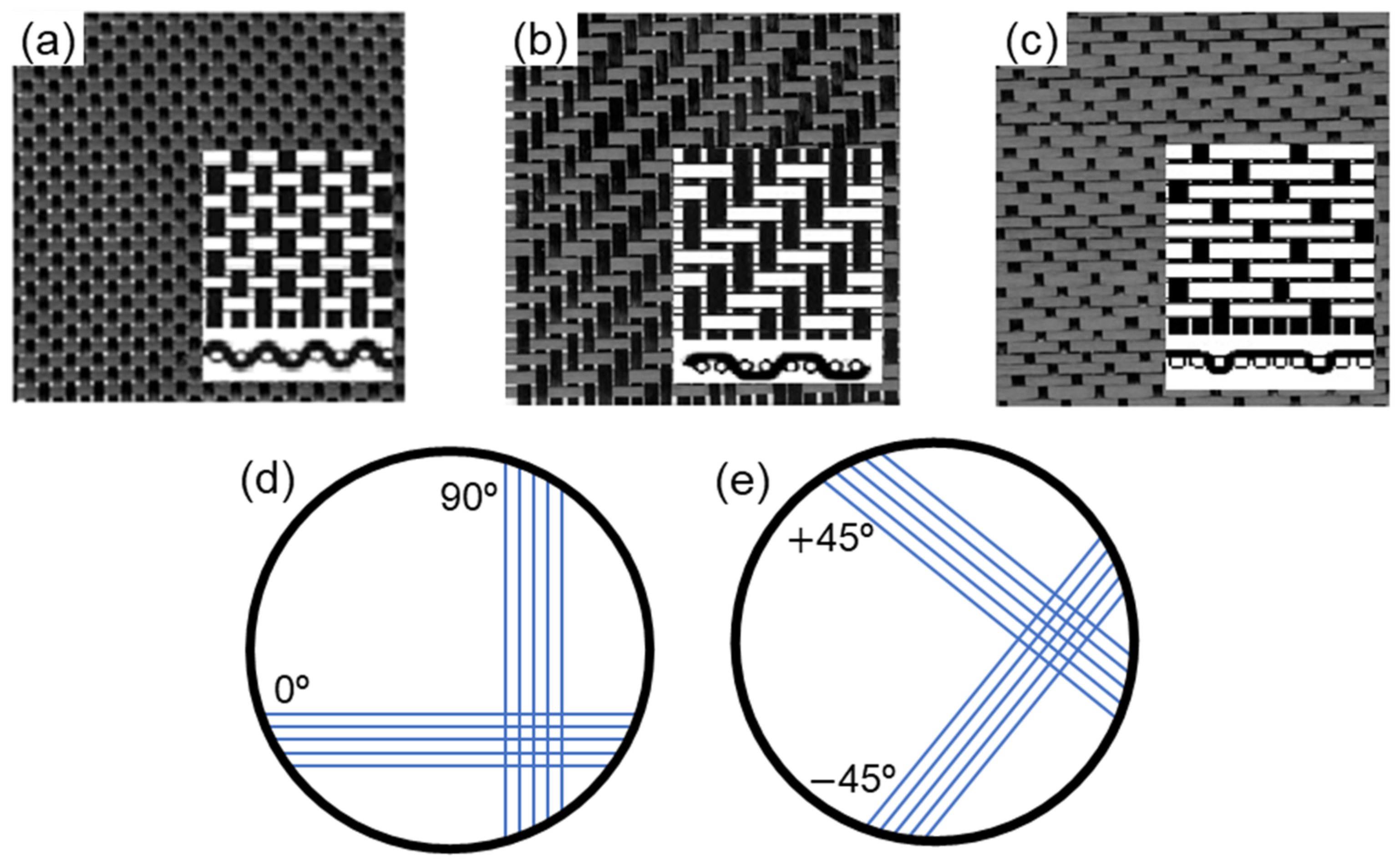
2.1. Fiber Reinforcements Characteristics

Carbon fiber fabrics used for this work are compounds by warp and weft yarns, orthogonally crossed with a bidirectional reinforcing effect. All fabrics were from HaxForce®, Texas, US. Four reinforcement types were used: plain weave, twill, satin, Non-Crimp Fabric—NCF 0/90, and NCF ± 45, as illustrated in Figure 1. The NCF presents no warp and weft since reinforcement directions are connected by polystyrene (PS) stitching. Moreover, Table 1 presents the reinforcement specification for the drapability test. Architecture represents warp and weft relations for plain, twill, and satin. The dimension adopted for the drapability test was 250 × 250 mm.
All fibers are from Hexcel® (Stamford, CT, USA), in which the fibers for plain, twill, and satin fabrics have filaments with 3 k of fibers, a tensile strength of 4723 MPa, ultimate elongation 1.8%, weight/length of 0.21 g/m, tow cross-section area 0.12 mm2. For both NCFs, the filaments have 6 k fibers, tensile strength of 5516 MPa, ultimate elongation 1.8%, weight/length 0.22 g/m, tow cross-section area 0.13 mm2. The fiber diameter is 7.1 μm, with 95% carbon. The fabrics have a weight ≈ 193 g/m2.

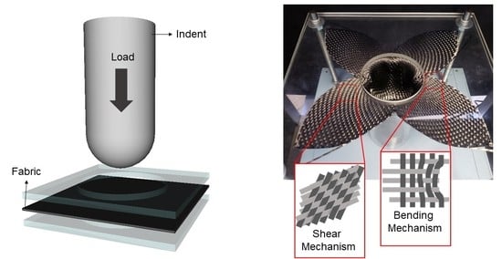
2.2. Experimental Structure

The test was performed following the Kissinger et al. study [35]. Figure 2 illustrates the device used, in which the first part is composed of a steel indent with a spherical head of 70 mm in diameter and 130 mm in length in the body. For the test, only 90 mm in length was used to deform the fabric. The second part is a device that holds the fabric between two polymethyl methacrylate (PMMA) plates with 8 mm thickness. An orifice of 80 mm diameter was made in each plate, where the indent could drape the fabric. The PMMA plates were used to improve the visualization records during the test, ensuring no stress on all fabrics. The third part of drapability equipment was the universal testing machine Shimadzu AG-X, where the platform created was fixed, and the indent was fixed with a 5 kN load-cell sensor system. The platform position needs to ensure that the spherical indent will be inserted in the middle of the plate orifice to avoid data acquisition errors. The Drapability test was performed in five specimens for each fabric type, using 10 mm·min−1 of speed and maximal displacement indent of 90 mm. A solid Teflon spray was inserted on the indent to avoid friction with the fabric during the test.

2.3. Optical Microscopy

The optical microscopy analysis was performed using Zeiss equipment (Aalen, Germany), Axio imager Z2m, and the Nikon d3200 camera (Tokyo, Japan). Images were post-processed using ImageJ software to measure the fiber angles, directions, and distances between the wefts. The images were obtained on the 3D fabric body and indented head.

2.4. Deformation Energy Determination

The drapability test was performed using Shimadzu AG-X to obtain load applied versus vertical displacement data. These data generate a curve with approximately 50 thousand points. Therefore, the curve is integrated to calculate the necessary energy for drapability, as shown in Figure 3. Therefore, using the integral method, the energy required for the deformation of each fabric was calculated.
The analysis of variance (ANOVA) was carried out for all results (energy and deformation parameters). Variance analysis was performed using Minitab18 for a double factor considering the reinforcement architecture and measurement parameter, using α = 0.05 for 95% of reliability.

3. Results

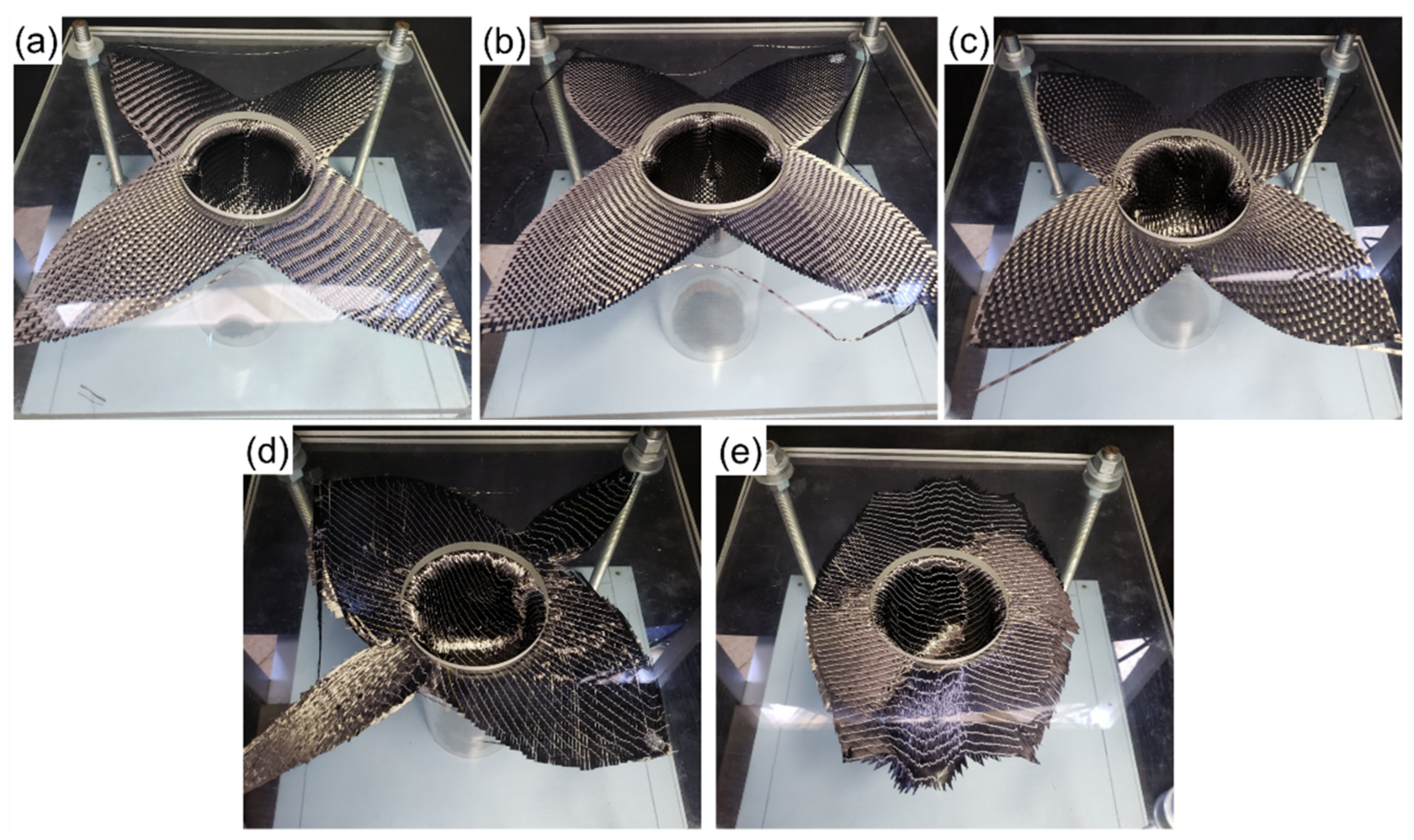
3.1. Drapability: Qualitative Analysis

The final stage of each test is represented in Figure 4. The final form differs from the square dimension presented at the beginning (250 mm × 250 mm) since each reinforcement has a different drape capability associated with fiber direction, warp/weft relation, bending and shear mechanisms.
The plain weave, twill, and satin fabrics present similar geometry at the end of the test (Figure 4a–c). The generated shape of these three fabrics is a flower-like image, considering the yield angle (0/90) in response to the load distribution in each part of the fabric. The load distribution causes a scissors shear in both fibers orientations, creating a locking angle between warp/weft, as showed by Molnár et al. [8]. Figure 5 illustrates the fiber movement behavior during the drapability test, considering fiber motion mechanisms as a load distribution function. The flower region (dark color) represents the shear mechanism, which changes the warp/weft orientation until the locking angle and the fiber twist occur. Moreover, the other regions exhibit a slipping and bending mechanism regarding the load direction applied.
A greater uniformity degree is found for satin due to warp and weft relation, which favors malleability, providing an equal load distribution across the fabric. The symmetry of plain weave and twill fabrics (1 × 1 and 2 × 2 warp/weft ratio, respectively) contributes to the drape capability—considering that the locking angle occurs more quickly, increasing the deformation defects generated in the fabric, i.e., fiber misalignment, increasing in space between warm/weft and fiber breakage [12].
Visual analysis of NCF 0/90 was different from NCF ± 45 fibers orientation. However, NCF 0/90 final format is similar to the plain, twill, and satin fabrics. The PS stitching was a factor that influenced the reinforcement drapability, blocking the fiber shear and resulting in nonuniformity drape movement. The device shortened the entire NCF ± 45 reinforcement, i.e., reinforcement moves into the mold from all sides, generating roughness and compression on fibers. The NCF ± 45 prevents angular movement (angle lock absence), facilitating the sliding and fibers agglomeration. The bending and shear mechanisms regions are switched to the NCF ± 45 fabric compared to the other fabric due to the fiber orientation, which promotes the shear behavior—responsible for the increase in the agglomeration and wrinkling of fibers.
Figure 6 and Figure 7 exhibit the visual fabric deformation along the indent body region. In Figure 6, all fabrics exhibit fiber wrinkling mechanism, fiber agglomeration, warp/weft space, and change of fiber directions, resulting in a high degree of deformation. Thus, the deformation follows: plain weave (Figure 6a,b) > twill (Figure 6c,d) > satin (Figure 6e,f). The larger deformation of plain and twill fabrics draped fabric (e.g., large misalignment, spaces between yarns, among others) could reduce final component mechanical properties since those regions will present fiber absence, warping, waviness, and other defects that act as stress concentrators [36,37]. Satin is the fabric that obtained more regular fiber distortion since its architecture (warp/weft space) distributes the deformation structure without inducing significant fiber misalignment, as shown in Figure 6a,b. No gaps and wrinkling are macroscopic visible in the satin fabric after the drapability test, which confirms the previous analysis.
NCF, for both cases, demonstrates a slipping of each fiber layer and high roughness due to the folding effect imposed by stitching (Figure 7). PS stitching is a positive factor in keeping fibers bonded without creating gaps, as in other fabrics. However, the stitching locked the fibers, anticipating the trellis-effect. As a matter of fact, space between warp/weft, fiber wrinkling, and changes in fiber directions are also presented in NCF 0/90 and NCF ± 45 after the drape formation. The NCF 0/90 keeps the flower-like, referring to the load distribution behavior shown in Figure 5. On the other hand, NCF ± 45 annulled this behavior due to initial fiber direction.

3.2. Drapability: Quantitative Analysis

The deformation image processing (ImageJ) was conducted to quantify the space and angular relation between warp/weft to measure the change according to the fabric deformation before and after the drape test. Microscopic analysis was carried out in fabric keeping 3D format. Table 2 presents the space between fiber yarns, in which the average follows the sequence: plain > twill > satin, confirming the previous qualitative analysis. Satin fabric presents no significant change in the spatial relationship between the filaments associated with easier fiber sliding without changing the initial fabric characteristics.
NCF presents a negative difference after the test because of fiber compaction, which increases fiber agglomeration and wrinkling mechanisms. This behavior is higher for NCF 0/90 due to load distribution mechanisms (bending and shear) combined with stitching locking the fiber deformation, which is reduced for NCF ± 45—higher fiber slipping mechanism.
The angular relationship between warp/weft before and after the test at the 3D body is shown in Table 3. The average angle change could be detrimental to the mechanical behavior since this performance creates the yarn locking angle, fiber wrinkling, and change in orientation [32,38]. The same behavior is found here, where it is possible to observe a correlation between modified angle and space generated during the three-dimensional forming test. The fabric with the lowest angle difference is satin, keeping a similar angular variation between yarn before and after the test. The greatest angular changes are present for plain and twill fabrics due to the scissors shear at the fabric edge regions. For NCF 0/90 and NCF ± 45 fabrics, fiber orientation changes due to the stitch, which locks regular fiber slip. In addition, the 2 × 2 ratio (twill) generates less space and angular modification compared with the 1 × 1 ratio (plain); meanwhile, the NCF ± 45 has also increased the defects formation in the 3D region (indent body).

3.3. Drapability Deformation Energy

The mechanical test was performed on five specimens for each fabric used in this study. Figure 8 exhibits the average load versus displacement until the maximum displacement tested, i.e., 90 mm. Irregularities in each curve indicate fabric slips, shear, bending, and fiber ruptures. These fabric structure non-linearity causes detrimental properties for fabric during drape processing or 3D form application, disfavoring final mechanical properties of the component [39,40,41,42].
The mechanical behavior shown in Figure 8 follows the load sequence: plain < twill < satin < NCF 0/90 < NCF ± 45. In other words, plain fabric presents the lowest resistance to the 3D formation; meanwhile, NCF ± 45 exhibits the highest resistance to drape. The results are in accordance with the deformation analysis presented in the previous section—warp/weft space and angle.
Table 4 presents the required energy to drape fabric. In this analysis, the work is quantified as the energy required to accomplish the drapability process for each fabric. An increase in energy means a lower fabric flexibility degree—resulting in more pressure for the indenting process and higher cost [43]. Considering that the energy is directly proportional to the applied load, the fabrics present the same energy sequence aforementioned. The reinforcements with higher energy to drape are NCF 0/90 and NCF ± 45; meanwhile, twill and plain woven presented less energy. Satin exhibits an intermediate result of energy. According to required energy growth, there is an increase in the standard deviation since the greater reinforcement movement occurs in each fabric.
Drapability test results show that the plain and twill fibrous fabric presents less ultimate load required for folding and, consequently, a lower amount of energy required to accomplish the three-dimensional format. This fact highlights both woven as good malleability. However, the visual deformation analysis presents a high misalignment degree and fiber wrinkling. The warp/weft symmetric relation induces a premature lock angle, creating greater difficulty for the 3D formation.
Both NCFs present a high necessary load and energy for draping, 4–5 times higher than the plain and twill fabrics. NCF reinforcement presents great roughness throughout the fabric, high misalignment in the folded region, and a high deformity drape, invalidating its use for complex geometries in a real component application. In addition, the PS stitching of reinforcement influences the draping process, preventing fibers from regular slipping or shearing. The tested material is particularly stressed due to the stitching blocking movement, forming a slight zigzag shape and fiber wrinkling.
Satin architecture allowed great malleability due to its intersection method of warp/weft, making the fabric more flexible. With high space in yield relation, the reinforcement weft generates a large elasticity modulus, appropriate behavior for three-dimensional structures. Due to their barely joined wefts, satin tends to shift, even presenting intermediate energy required for drape.
The analysis of variance (ANOVA) was finally performed based on the experimental results of fabric deformation (deformation—mm), modification of the yield angle (angle change—%), and energy required for three-dimensional conformation of the fabric (energy—J), presented in Table 5. From this analysis, the values with F > Fcritical indicate that the null hypothesis (H0) is false, and the parameter presents an influence on the response. This behavior occurred for all parameters since each type of fabric presents a different draping behavior. This analysis is confirmed by a p-value ≤ 0.01, guaranteeing reliability of 95%.
The percentage of contribution (PC) values were calculated from the ANOVA results, in which all measurement parameters exhibit an influencing factor on the drapability results. All three parameters have values close to each other. However, the deformations related to the fiber misalignment (angle and yield distance) affect the drapability behavior more than the energy required for deformation, being important values to be considered in the 3D conformation of the fabrics.
Solver optimization was carried out using each value found for deformation between warn/weft, angle changing, energy, and the contribution percentage as weight factors. The optimization process aims to minimize deformation and required energy, accessing the fabric architecture with less changing on initial properties. In other words, optimization was conducted to access the fabric with lower defect formation and lower required energy for the drapability process. Therefore, satin fabric shows the lowest influence of drapability (i.e., 401), followed by NCF 0/90 (935) < twill (1311) < NCF ± 45 (1718) < plain (3716).

4. Conclusions

This study was carried out to evaluate the drapability behavior of several fibrous fabrics into a spherical indent. The experimental measurement of required energy and fiber misalignment analysis was important for a comparative investigation of drapability behavior to establish the contribution of textile architecture to drape in a 3D geometry. In addition, the fabric drapability testing presented good comparative results among the five fibrous reinforcements analyzed through the method applied.
The test determined that the fabric malleability for a three-dimensional structure depends on fabric architecture (warp/weft relation), fiber direction, and the presence of stitching. Satin fabric presented higher uniformity in load distribution over the displacement, symmetry on drape capability, the lowest deformation degree, and fiber misalignment, confirmed by ANOVA and optimization process. Even requiring greater energy for draping than plain and twill fabrics, satin is the most suitable fabric for three-dimensional shapes without fiber wrinkling, ensuring the initial fabric characteristic in a complex geometry structure.

Author Contributions

Conceptualization, M.O.C. and I.G.; methodology, Y.P.C.; validation, M.P., Y.P.C. and F.M.; formal analysis, F.M.; investigation, Y.P.C.; resources, M.O.C. and F.M.; data curation, F.M.; writing—original draft preparation, Y.P.C.; writing—review and editing, F.M.; visualization, M.O.C. and I.G.; supervision, F.M.; project administration, M.O.C.; funding acquisition, M.O.C. All authors have read and agreed to the published version of the manuscript.

Funding

This research was funded by Fundação de Amparo À Pesquisa do Estado de São Paulo—Brazil (FAPESP) process number 2017/10606-4, 2020/09422-9, 2021/05706-5 and Coordenação de Aperfeiçoamento de Pessoal de Nível Superior—Brazil (CAPES)—Finance Code 001.

Institutional Review Board Statement

Not applicable.

Informed Consent Statement

Not applicable.

Data Availability Statement

Not applicable.

Conflicts of Interest

The authors declare no conflict of interest.

References

  1. Almeida, J.H.S.; Bittrich, L.; Jansen, E.; Tita, V.; Spickenheuer, A. Buckling optimization of composite cylinders for axial compression: A design methodology considering a variable-axial fiber layout. Compos. Struct. 2019, 222, 110928. [Google Scholar] [CrossRef]
  2. Almeida, J.H.S.; Angrizani, C.C.; Botelho, E.C.; Amico, S.C. Effect of fiber orientation on the shear behavior of glass fiber/epoxy composites. Mater. Des. 2015, 65, 789–795. [Google Scholar] [CrossRef]
  3. Potluri, R.; Dheeraj, R.S.; Vital, G.V.V.N. Effect of stacking sequence on the mechanical & thermal properties of hybrid laminates. Mater. Today Proc. 2018, 5, 5876–5885. [Google Scholar] [CrossRef]
  4. Monticeli, F.M.; Almeida, J.H.S.A., Jr.; Neves, R.M.; Ornaghi, F.G.; Ornaghi, H.L. On the 3D void formation of hybrid carbon/glass fiber composite laminates: A statistical approach. Compos. Part A Appl. Sci. Manuf. 2020, 137, 106036. [Google Scholar] [CrossRef]
  5. Kim, H.J.; Kim, H.S.; Lee, G.Y.; Kim, M.S.; Min, S.H.; Keller, R.; Ihn, J.B.; Ahn, S.H. Three-dimensional carbon fiber composite printer for CFRP repair. Compos. Part B Eng. 2019, 174, 106945. [Google Scholar] [CrossRef]
  6. Härter, F.V.; Souza, J.A.; Isoldi, L.A.; Santos, E.D.D.; Amico, S.C. Transverse permeability determination and influence in resin flow through an orthotropic medium in the RTM process. Rev. Mater. 2017, 22, e-11851. [Google Scholar] [CrossRef]
  7. Ashir, M.; Hahn, L.; Kluge, A.; Nocke, A.; Cherif, C. Development of innovative adaptive 3D Fiber Reinforced Plastics based on Shape Memory Alloys. Compos. Sci. Technol. 2016, 126, 43–51. [Google Scholar] [CrossRef]
  8. Molnár, P.; Ogale, A.; Lahr, R. Mitschang, Influence of drapability by using stitching technology to reduce fabric deformation and shear during thermoforming. Compos. Sci. Technol. 2007, 67, 3386–3393. [Google Scholar] [CrossRef]
  9. Friedrich, K.; Maier, M.; Neitzel, M. Manufacturing and testing of composite materials and structures. European cooperative research examples. Mech. Compos. Mater. 2000, 36, 429–438. [Google Scholar] [CrossRef]
  10. Hosseini, M.R.; Taheri-Behrooz, F.; Salamat-talab, M. Mode I interlaminar fracture toughness of woven glass/epoxy composites with mat layers at delamination interface. Polym. Test. 2019, 78, 105943. [Google Scholar] [CrossRef]
  11. Rozant, O.; Bourban, P.E.; Månson, J.A.E. Drapability of dry textile fabrics for stampable thermoplastic preforms. Compos. Part A Appl. Sci. Manuf. 2000, 31, 1167–1177. [Google Scholar] [CrossRef]
  12. Omeroglu, S.; Karaca, E.; Becerir, B. Comparison of Bending, Drapability and Crease Recovery Behaviors of Woven Fabrics Produced from Polyester Fibers Having Different Cross-sectional Shapes. Text. Res. J. 2010, 80, 1180–1190. [Google Scholar] [CrossRef]
  13. Kurita, H.; Suganuma, M.; Wang, Y.; Narita, F. k-Means Clustering for Prediction of Tensile Properties in Carbon Fiber-Reinforced Polymer Composites. Adv. Eng. Mater. 2022, 24, 2101072. [Google Scholar] [CrossRef]
  14. Shaik, F.; Ramakrishna, M.; Varma, P.D. A review on fabrication of thermoset prepreg composites using out-of-autoclave technology. INCAS Bull. 2021, 13, 133–149. [Google Scholar] [CrossRef]
  15. Tanaka, K.; Ushiyama, R.; Katayama, T.; Enoki, S.; Sakamoto, H. Formability Evaluation of Carbon Fiber NCF by a Non-Contact 3D Strain Measurement System and the Effects of Blank Folder Force on its Formability. In High Performance and Optimum Design of Structures and Materials; WIT Press: Southampton, UK, 2014; pp. 317–326. [Google Scholar]
  16. Hesseler, S.; Stapleton, S.E.; Appel, L.; Schöfer, S.; Manin, B. 11—Modeling of Reinforcement Fibers and Textiles. In Advances in Modeling and Simulation in Textile Engineering; Woodhead Publishing: Cambridge, UK, 2021; pp. 267–299. [Google Scholar]
  17. Malysheva, G.V.; Tumasova, M.S.; Tepishkina, E.S. Evaluation of forming properties of fabrics from carbon, glass, and organic fibers. Polym. Sci. Ser. D 2016, 9, 223–227. [Google Scholar] [CrossRef]
  18. Mehdikhani, M.; Gorbatikh, L.; Verpoest, I.; Lomov, S.V. Voids in fiber-reinforced polymer composites: A review on their formation, characteristics, and effects on mechanical performance. J. Compos. Mater. 2019, 53, 1579–1669. [Google Scholar] [CrossRef]
  19. Windhammer, A.; Wuchner, R.; Bletzinger, K.-U. Drape Simulation for Non-Developable Multi-Layered CFRP Structures Focusing on Optimized Cutting Patterns. In Proceedings of the European Congress on Computational Methods in Applied Sciences and Engineering, ECCOMAS 2012, Vienna, Austria, 10–14 September 2012. [Google Scholar]
  20. Yang, L.; Kim, K.O.; Takatera, M. Measurement of local shear deformation in fabric drape using three-dimensional scanning. Text. Res. J. 2021, 91, 885–898. [Google Scholar] [CrossRef]
  21. Pil, L.; Bensadoun, F.; Pariset, J.; Verpoest, I. Why are designers fascinated by flax and hemp fibre composites? Compos. Part A Appl. Sci. Manuf. 2016, 83, 193–205. [Google Scholar] [CrossRef]
  22. Allaoui, S.; Boisse, P.; Chatel, S.; Hamila, N.; Hivet, G.; Soulat, D.; Vidal-salle, E. Experimental and numerical analyses of textile reinforcement forming of a tetrahedral shape. Compos. Part A 2011, 42, 612–622. [Google Scholar] [CrossRef]
  23. Ahmad, F.; Yuvaraj, N.; Bajpai, P.K. Effect of reinforcement architecture on the macroscopic mechanical properties of fiberous polymer composites: A review. Polym. Compos. 2020, 41, 2518–2534. [Google Scholar] [CrossRef]
  24. Huang, Z.; Ma, W.; Jia, C.; Lei, X.; Zhang, Z. A deformation model and draping behavior analysis of plain weave fabric with low-twist yarn on continuous surface. Mater. Res. Express. 2022, 9, 055303. [Google Scholar] [CrossRef]
  25. Rath, J.-E.; Schwieger, L.-S.; Schüppstuhl, T. Robotic Die-Less Forming Strategy for Fiber-Reinforced Plastic Composites Production. Procedia CIRP 2022, 107, 1281–1286. [Google Scholar] [CrossRef]
  26. Bai, R.; Chen, B.; Colmars, J.; Boisse, P. Physics-based evaluation of the drapability of textile composite reinforcements. Compos. Part B 2022, 242, 110089. [Google Scholar] [CrossRef]
  27. ATaieb, H.; Mshali, S.; Sakli, F. Predicting fabric drapability property by using an artificial neural network. J. Eng. Fiber. Fabr. 2018, 13, 87–93. [Google Scholar] [CrossRef]
  28. Hubner, M.; Diestel, O.; Sennewald, C.; Gereke, T.; Cherif, C. Simulation of the Drapability of Textile Semi-Finished Products with Gradient-Drapability Characteristics by Varying the Fabric Weave. Fibres Text. East. Eur. 2011, 20, 88–93. [Google Scholar]
  29. Hineno, S.; Yoneyama, T.; Tatsuno, D.; Kimura, M. Fiber deformation behavior during press forming of rectangle cup by using plane weave carbon fiber reinforced thermoplastic sheet. Procedia Eng. 2014, 81, 1614–1619. [Google Scholar] [CrossRef]
  30. Kondratiev, A.; Haidachuck, O.; Tsaritsynskyi, A. Research of Safe Technology of Impregnation of Heated Reinforcing Materials with Binder. Mater. Sci. Forum 2021, 1038, 119–128. [Google Scholar] [CrossRef]
  31. Tan, J.; Jiang, G.; Gao, Z.; Ma, P.; Zheng, P. Development and mechanical properties of three-dimensional flat-knitted fabrics with reinforcement yarns. J. Ind. Text. 2022, 51, 2071–2088. [Google Scholar] [CrossRef]
  32. Hassan, M.H. A mini review on manufacturing defects and performance assessments of complex shape prepreg-based composites. Int. J. Adv. Manuf. Technol. 2021, 115, 3393–3408. [Google Scholar] [CrossRef]
  33. Amor, N.; Noman, M.T.; Petru, M. Classification of textile polymer composites: Recent trends and challenges. Polymers 2021, 13, 2592. [Google Scholar] [CrossRef]
  34. Saboktakin, A. 3D textile preforms and composites for aircraft strcutures: A review. Int. J. Aviat. Aeronaut. Aerosp. 2019, 6, 2. [Google Scholar] [CrossRef] [Green Version]
  35. Kissinger, C.; Neitzel, M.M. Advanced Materials for RTM-Processing-Characterization and Application of Non Crimp Fabrics (NCF). In Materials for Transportation Technology; Wiley: Hoboken, NJ, USA, 2005; pp. 176–182. [Google Scholar] [CrossRef]
  36. Uhlig, K.; Bittrich, L.; Spickenheuer, A.; Almeida, J.H.S., Jr. Waviness and fiber volume content analysis in continuous carbon fiber reinforced plastics made by tailored fiber placement. Compos. Struct. 2019, 222, 110910. [Google Scholar] [CrossRef]
  37. Van de Werken, n.; Tekinalp, H.; Khanbolouki, P.; Ozcan, S.; Williams, A.; Tehrani, M. Additively manufactured carbon fiber-reinforced composites: State of the art and perspective. Addit. Manuf. 2020, 31, 100962. [Google Scholar] [CrossRef]
  38. Kim, D.J.; Yu, M.H.; Lim, J.; Nam, B.; Kim, H.S. Prediction of the mechanical behavior of fiber-reinforced composite structure considering its shear angle distribution generated during thermo-compression molding process. Compos. Struct. 2019, 220, 441–450. [Google Scholar] [CrossRef]
  39. Bodaghi, M.; Cristóvão, C.; Gomes, R.; Correia, N.C. Experimental characterization of voids in high fibre volume fraction composites processed by high injection pressure RTM. Compos. Part A Appl. Sci. Manuf. 2016, 82, 88–99. [Google Scholar] [CrossRef]
  40. Yokozeki, T.; Ogasawara, T.; Ishikawa, T. Effects of fiber nonlinear properties on the compressive strength prediction of unidirectional carbon-fiber composites. Compos. Sci. Technol. 2005, 65, 2140–2147. [Google Scholar] [CrossRef]
  41. Yurgartis, S.W. Measurement of small angle fiber misalignments in continuous fiber composites. Compos. Sci. Technol. 1987, 30, 279–293. [Google Scholar] [CrossRef]
  42. Li, Y.; Stier, B.; Bednarcyk, B.; Simon, J.W.; Reese, S. The effect of fiber misalignment on the homogenized properties of unidirectional fiber reinforced composites. Mech. Mater. 2016, 92, 261–274. [Google Scholar] [CrossRef]
  43. Joshuva, A.; Sugumaran, V. A study of various blade fault conditions on a wind turbine using vibration signals through histogram features. J. Eng. Sci. Technol. 2018, 13, 102–121. [Google Scholar]
Figure 1. Reinforcements architectures: (a) Plain; (b) Twill; (c) Satin; (d) NCF 0/90; and (e) NCF ± 45.
Textiles 02 00027 g001
Figure 2. Drapability device (based on Ref. [35]).
Textiles 02 00027 g002
Figure 3. Energy measurement method.
Textiles 02 00027 g003
Figure 4. Reinforcement form at the end of the test: (a) plain; (b) twill; (c) satin; (d) NFC 0/90, and (e) NCF ± 45.
Textiles 02 00027 g004
Figure 5. Load distribution during drapability test—fiber shear and bending misalignment.
Textiles 02 00027 g005
Figure 6. Optical microscopic images of fabric deformation: (a,b) plain weave 1 × 1; (c,d) twill weave; and (e,f) Satin.
Textiles 02 00027 g006
Figure 7. Optical microscopic images of fabric deformation: (a,b) NCF 0/90; (c,d) NCF ± 45.
Textiles 02 00027 g007
Figure 8. Load vs. displacement for each reinforcement deformation.
Textiles 02 00027 g008
Table 1. Reinforcement characteristics for drapability test.
FabricArchitectureFibersHeight (mm)Dimension (mm)
Plain1 × 1IM7 GP0.31250 × 250
Twill2 × 2IM7 GP0.30250 × 250
Satin4 × 1IM7 GP0.32250 × 250
NCFBiaxial (0/90)IM7 51310.57250 × 250
NCFBiaxial (±45)IM7 51310.48250 × 250
Table 2. Average warp/weft space relation before and after deformation test.
Warp/Weft
Space (mm)
BeforeAfterAverage
Difference (%)
X-AxisY-AxisX-AxisY-Axis
Plain0.5 ± 0.10.5 ± 0.10.6 ± 0.41.4 ± 0.588.6 ↑
Twill0.5 ± 0.20.3 ± 0.10.7 ± 0.30.5 ± 0.232.5 ↑
Satin0.2 ± 0.10.2 ± 0.10.3 ± 0.20.3 ± 0.20.1 ↑
NCF 0/905.9 ± 0.61.7 ± 0.35.8 ± 0.71.2 ± 0.28.0 ↓
NCF ± 454.8 ± 0.11.8 ± 0.14.6 ± 0.21.2 ± 0.418.7 ↓
Table 3. Average warp/weft angle relation before and after deformation test.
Warp/Weft Angle (°)BeforeAfterDifference (%)
Plain90.056.137.7
Twill90.080.510.6
Satin90.084.55.5
NCF 0/9090.079.411.8
NCF ± 4590.068.823.6
Table 4. Deformation energy for draping each fabric (J = N·m).
EnergyPlainTwillSatinNCF 0/90NCF ± 45
Average1.82.15.48.210.7
a SD0.050.050.590.290.50
a—standard deviation (SD).
Table 5. ANOVA results.
ParameterFp-ValueFcriticalPC
Deformation (mm)582.656.8 × 10−104.6039.54
Angle change (%)495.431.0 × 10−24.4533.62
Energy (J)5.951.0 × 10−23.8426.84
Publisher’s Note: MDPI stays neutral with regard to jurisdictional claims in published maps and institutional affiliations.

