Review

A Comprehensive Review of the Development of Perovskite Oxide Anodes for Fossil Fuel-Based Solid Oxide Fuel Cells (SOFCs): Prospects and Challenges

Department of Chemistry, University of Calgary, Calgary, AB T2N 1N4, Canada
Physchem 2025, 5(3), 25; https://doi.org/10.3390/physchem5030025
Submission received: 31 March 2025 / Revised: 9 June 2025 / Accepted: 20 June 2025 / Published: 23 June 2025
(This article belongs to the Section Electrochemistry)

Abstract

Solid oxide fuel cells (SOFCs) represent a pivotal technology in renewable energy due to their clean and efficient power generation capabilities. Their role in potential carbon mitigation enhances their viability. SOFCs can operate via a variety of alternative fuels, including hydrocarbons, alcohols, solid carbon, and ammonia. However, several solutions have been proposed to overcome various technical issues and to allow for stable operation in dry methane, without coking in the anode layer. To avoid coke formation thermodynamically, methane is typically reformed, contributing to an increased degradation rate through the addition of oxygen-containing gases into the fuel gas to increase the O/C ratio. The performance achieved by reforming catalytic materials, comprising active sites, supports, and electrochemical testing, significantly influences catalyst performance, showing relatively high open-circuit voltages and coking-resistance of the CH4 reforming catalysts. In the next step, the operating principles and thermodynamics of methane reforming are explored, including their traditional catalyst materials and their accompanying challenges. This work explores the components and functions of SOFCs, particularly focusing on anode materials such as perovskites, Ruddlesden–Popper oxides, and spinels, along with their structure–property relationships, including their ionic and electronic conductivity, thermal expansion coefficients, and acidity/basicity. Mechanistic and kinetic studies of common reforming processes, including steam reforming, partial oxidation, CO2 reforming, and the mixed steam and dry reforming of methane, are analyzed. Furthermore, this review examines catalyst deactivation mechanisms, specifically carbon and metal sulfide formation, and the performance of methane reforming and partial oxidation catalysts in SOFCs. Single-cell performance, including that of various perovskite and related oxides, activity/stability enhancement by infiltration, and the simulation and modeling of electrochemical performance, is discussed. This review also addresses research challenges in regards to methane reforming and partial oxidation within SOFCs, such as gas composition changes and large thermal gradients in stack systems. Finally, this review investigates the modeling of catalytic and non-catalytic processes using different dimension and segment simulations of steam methane reforming, presenting new engineering designs, material developments, and the latest knowledge to guide the development of and the driving force behind an oxygen concentration gradient through the external circuit to the cathode.

1. Introduction

Solid oxide fuel cell (SOFC) power generation is a process that can be used for automobiles and household appliances, owing to its high power-generation characteristics with maximum electrical efficiency. The first application of SOFCs using zirconium, yttrium, cerium, lanthanum, and tungsten oxide at 1000 °C in 1937 showed the employability of SOFCs for industrial scale applications, along with their economic feasibility [1].
Fuel cells, including high-temperature fuel cells, proton exchange membrane fuel cells (PEMFCs), alkaline fuel cells (AFCs), and solid acid fuel cells (SAFCs), can be considered as electrochemical devices that convert chemical energy into electrical energy (Figure 1).
Hydrocarbon fuel converts chemical energy, considering bond strengths and distances to measure small sizes and time scales, leading to the conversion of chemical energy directly into electrical energy by electrochemical reactions in the fuel cells. At the anode, carbon formation is usually thermodynamically favored with hydrocarbon fuels at low oxygen fugacities due to direct oxidation. In the electrolyte, protons or oxide ions could migrate by hopping from the OH site to the oxide ion site, depending on the conduction properties of this electrolyte material and the degree of mixed protons. High temperature SOFCs suggest the possibility of features such as the flexibility of using different fuels, offering great potential for the oxidation of reactant gas on the anode in the thickness of 10 to 20 μm, as well as optimal energy conversion efficiency. Thus, the unique features of SOFCs, coupled with their potential linkage to the cathode of the next cell to achieve the goal of resource conservation and environmental sustainability, are considered.
The prevention of carbon formation and the achievement of long-term stable performance have been the subject of SOFC research in recent years, where the focus is on the preparation of ceramic or composite materials able to catalyze the oxidation of hydrocarbon. Figure 2 schematically shows three different scenarios including external reforming, internal reforming, and direct hydrocarbon utilization.

1.1. SOFCs Role and Viability in Renewable Energy

SOFCs have been considered as one of the most promising technologies for generating power from hydrogen, natural gas, and other renewable fuels. Additionally, due to the endothermic reaction of reforming and the production of high-quality byproducts, high current density is achievable between 600–1000 °C. A single SOFC cell consists of thin electrolyte films deposited on thick substrates to enable stacking and the development of peripheral components compared to results for conventional systems, as depicted in Figure 3. The solid electrolyte is located between the cathode and anode transporting charge. This prevents electrons from acting as the transporting medium, which then transport through the external circuit. On the anode and cathode electrodes, the oxidation of fuels and the reduction of oxygen occur, respectively. During the process, the anode and cathode can corrode. Yttria-stabilized zirconia (YSZ) is an efficient electrolyte material in SOFCs, together with scandia-stabilized zirconia (ScSZ). Additionally, due to their high conductivity, gadolinia-doped ceria (GDC) and cerium gadolinium oxide (CGO) are interesting electrolyte materials for use in intermediate temperature SOFCs (IT-SOFCs). In another review paper, new functional semiconductors developed using the novel idea of a nano-SOFC suggested new paths for the R&D of SOFCs [4]. Semiconductor-ionic materials (SIMs)/semiconductor membranes (SMs) presenting fuel cell technology have been suggested for use in the hydrogen era over traditional battery technology. The main principle of the SOFC device is a reduction in the thickness of electrolytes to deliver better electrochemical performance. SOFCs, depending on the flow of oxide ions, can operate at low operating temperatures, awarding them crucial roles in the development of battery materials. To further improve electrochemical performance, the application of tubular SOFCs for stationary power plants offers a multitude of benefits, including remarkable results at intermediate and low operating temperatures. Advances in nanomaterial and semiconductor physics allows for the complete compensation for polarization losses and suggests that the electrolyte may not be considered to improve the functionality of the SOFC.
A simple way to show the efficiency of energy conversion on the concentration and activation overpotentials in terms of effective diffusion coefficients to evaluate the carbon mass is feeding by a syngas with a high CO content. The efficiency limit for heat engines can be entirely caused by porous-media transport and the heterogenous reforming chemistry within the anode as maximum efficiency = (T1 − T2)/T1, where T1 is the maximum temperature of the fluid in a heat engine, and T2 is the temperature at which the fluid is disposed. For instance, by retarding diffusion through plasma-driven surface modification, considering the apical and basolateral plasma membranes applied to the porous electrode manufacturing processes on the surface phase separation, followed by the Carnot efficiency limit, is 52%. For fuel cell operation, the maximum efficiency, which is much higher than that for heat engines, can be directly measured by ΔG/(−ΔH). Figure 4 represents different fuel cells using syngas and hydrogen produced by different types of fuel processing [6].

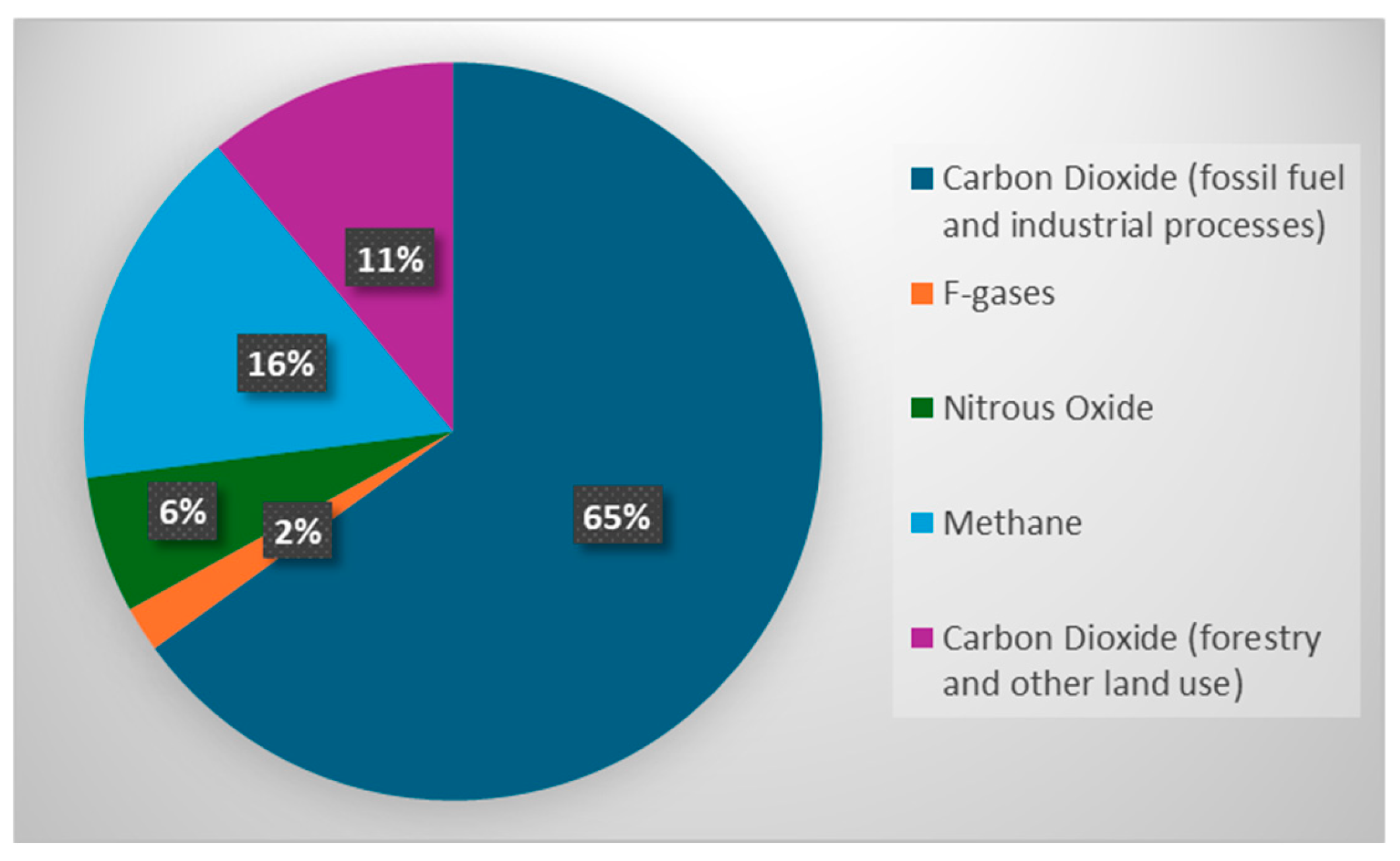
1.1.1. Potential Carbon Mitigation

The Paris Agreement, approved at the 21st Conference of the Parties, highlighted that to significantly decrease the risks and effects of climate change, the global mean temperature growth must be held well below 2 °C, and efforts to limit it to 1.5 °C above pre-industrial levels must be continued [7]. There are numerous processes used to produce electricity, such as fossil fuel burning for transportation, deforestation, and fossil fuel burning, that release greenhouse gas (GHG) emissions (Figure 5) [8]. The carbon-negative goal can be technically achieved by fuel cells to complete the conversion of syngas into power with additional methane reforming ability. The integration of biomass gasification and SOFC can mitigate CO2 emission using steam and heat generation via exhaust heat recovery.

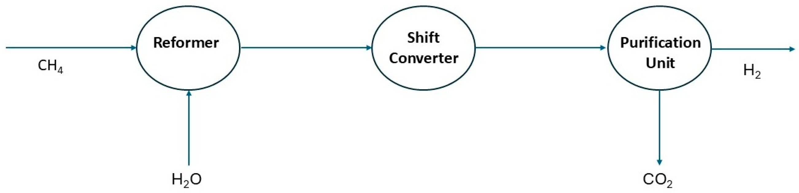
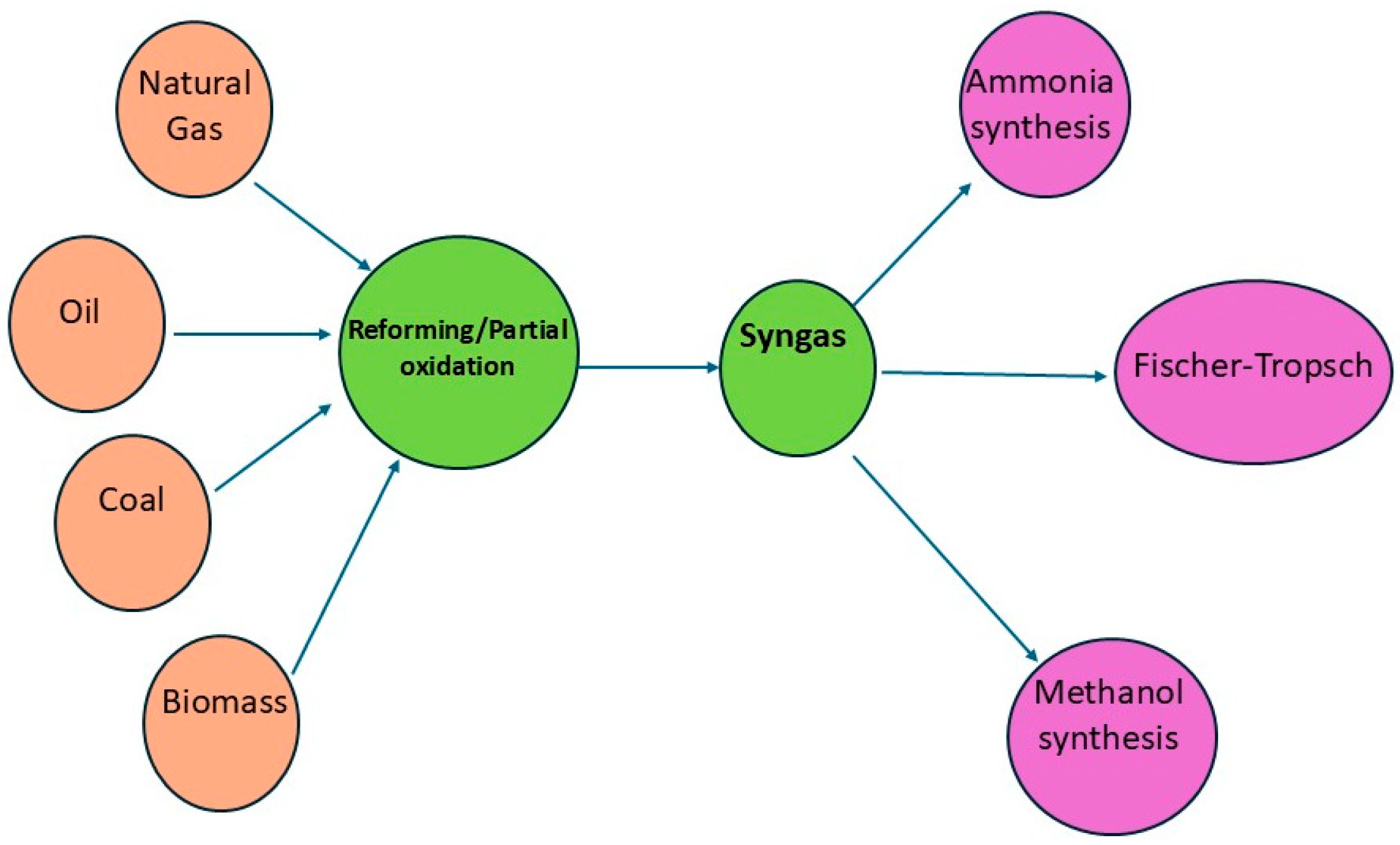
1.1.2. Syngas Production Strategies

Since biomass may be seen as a carbon-neutral feedstock, using thermochemical conversion techniques such as gasification to produce profitable syngas reduces greenhouse gas emissions [9]. Gasification technology involves novel strategies for tar removal to considerably reduce syngas production costs. Syngas produced from an indirect gasifier contains H2, CO, CO2, CH4, H2O, and various contaminants. These contaminants, such as alkali metals, sulfur, and chlorine, lead to high-temperature metal corrosion, acid corrosion of metals, and catalysts deactivation [10]. Fuel cells are considered as a promising combined heat and power (CHP) system that can directly utilize the syngas to achieve over 60% electrical efficiency. However, fuel cells have a limitation regarding syngas derived from biomass gasification, with high efficiency and low environmental impact using ash percentages of up to 20 wt%, which burns off at the sintering process and has a lower environmental impact compared to that of conventional fuels, followed by pyrolysis, which converts solid char and heavy hydrocarbons into the gas-producing burners fixed in the combustion chamber with the downstream process similar to that of a diesel burner. Generally, the protective coating on the cathode side meets the additional requirements, especially those of CTE compatibility, including ferritic stainlessness, with very specific chemical compositions. Since supercritical water has the ability of providing a homogenous reaction to explore metal alloys, it has already been considered as a reaction media and has been used in commercial applications during cell operation. Combining a gasification unit with the supercritical water unit leads to high conversion efficiency and clean syngas production (Figure 6).

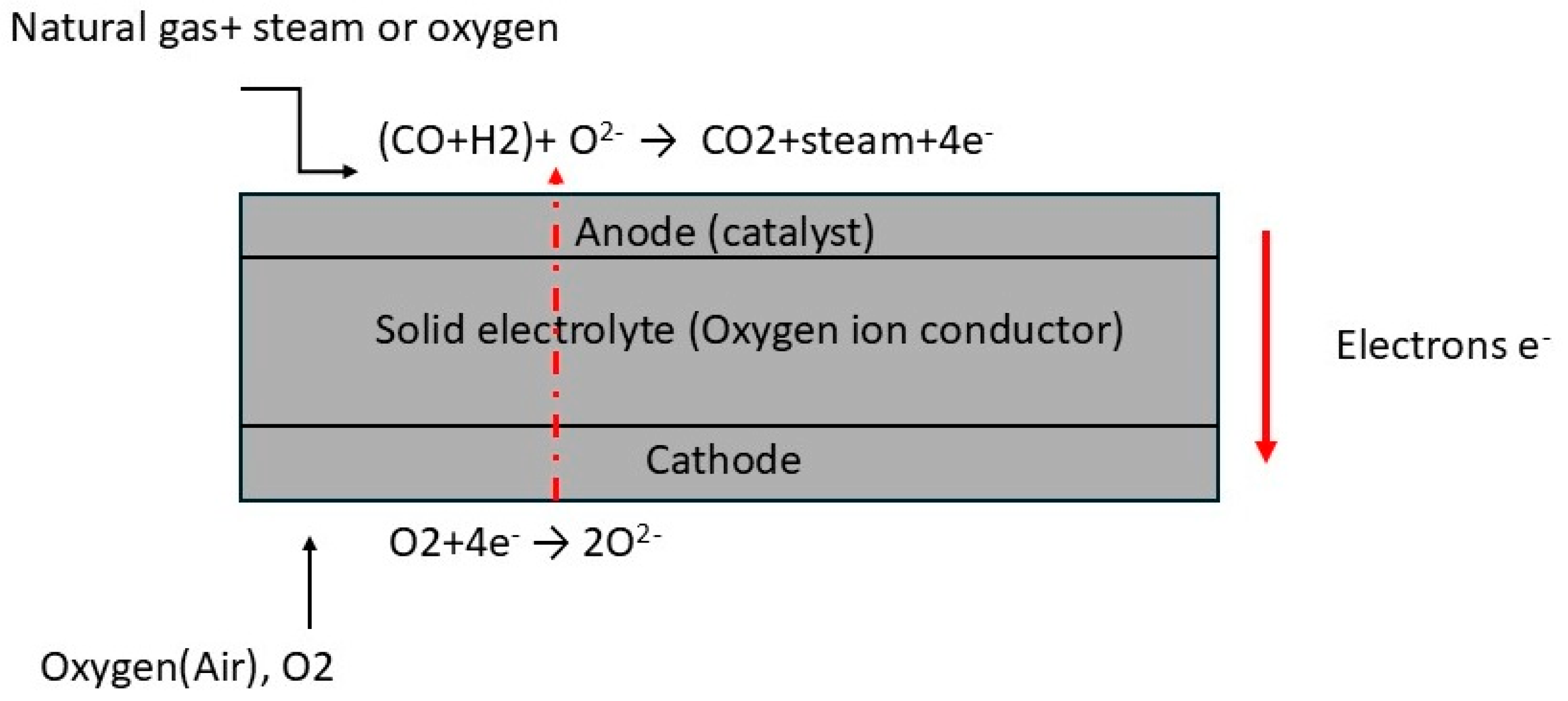
1.2. Operating Principles and Thermodynamics of Methane Reforming

Hydrogen is currently an important industrial product and has important future potential as a fuel. The main processes for hydrogen production based on the implementation of low carbon technologies, developing a clean and sustainable energy system, provides an overview of energy in the world and the importance of H2 energy. However, steam methane reforming (SMR) is one of the most important industrial processes for hydrogen production today. As shown in Figure 7, the basic steps in conventional SMR include the reformer, shift convertor, and purification unit to remove carbon dioxide [12]. The integration of SOFC and carbon capture to increase energy efficiency for SOFC cogeneration consisting of the recovery of the residual heat, usually not exceeding 200 °C considering the feasibility of developing such a hybrid system based on factors such as system size, emissions, and techno-economics, can intensify SMR design. This research attempts to overcome the problems of diffusional limitations, storing renewable energy in an energy carrier providing sustainable, green, and non-renewable resources, by identifying optimal operating conditions [13].
Carapellucci et al. investigated a thermodynamic study that can play a critical role in combining dry reforming with SOFC technology, guaranteeing high operating temperatures and significant recoverable heat to produce a fixed power [14]. They used an equilibrium model to partially reduce carbon emissions and proposed and identified a feasible and sustainable method to address the issues of climate change to achieve maximum H2 production and energy performance metrics. It is concluded that acting on the exhaust gases by installing a treatment plant able to operate on the entire exhaust flow downstream by combustion could produce a working fluid for industrial and energy applications. In another study, comparisons in terms of the techno-economic and life cycle assessment of SMR and DMR are used to investigate all kinds of oxygenated fuels, regardless of the oxygen content in their molecular structure relative to their smaller quenching distance and higher combustion temperature. It has been reported that for SMR, a high S/C ratio is beneficial for prohibiting the catalysts from inactivation. It is concluded that for SMR and DMR, the increase in temperature and the endothermic characteristic of the reaction make it possible to store and transport solar or other renewable sources of energy [15]. Jafarbegloo et al. conducted a chemical exergy study, coupled with the effect of reactant temperature, determining that exergy losses was the most significant parameter when compared with other parameters [16]. They compared the results for the SMR process, a CO2 compressor, and the utilization of natural gas as a feedstock to secure the bulk production of green hydrogen. They concluded that during DMR, first, CO2 reforming equilibrates and then SMR reaction provides the advantage for a post-combustion capture system via a tri-reforming reaction rather than the use of a huge fired-furnace in a conventional steam reformer. In the simulation and modeling section, it was assumed that hydrogen holds great potential for the achievement of the near-zero or zero carbon emissions of marine engines in the future. Figure 8 represents the effect of the composition of the oxidant portion (CO2 + H2O) on the mixed reforming performance at 800 °C under 1 bar of pressure. It shows that investigating the amount of carbon dioxide emissions at the source depends on the production route to calculate the activation energy and reaction rate.
Figure 9 shows the equilibrium CH4 conversions with increasing temperature measured at different S/C ratios and ambient pressure. It confirms that increasing S/C ratios at a constant temperature leads to higher methane conversion, and a complete conversion of CH4 can be obtained around 700 °C at ambient pressure (S/C > 2.5).
In another research study, ASPEN-HYSYS was used to develop simulation models for determining the exhaust gases which are heat transformed into the chemical energy of a new synthetic fuel [17]. All of the integration of biomass gasification with SOFCs was carried out using the Gibbs free energy minimization technique for T = 200–1000 °C and P = 1–3 bar, without considering side reactions. Figure 10 shows the process flow diagram for DMR using the Gibbs reactor and assumes nitrogen as the inert gas, with the products separated from the reactants using component splitter. It was reported that dry reforming conversion, which increases the use of catalysts in the gasification process, has been proven to be an effective method to elevate the hydrogen content in produced gas and syngas, and the increases from 400 to 800 °C and thereafter remain constant due to catalyst deactivation.

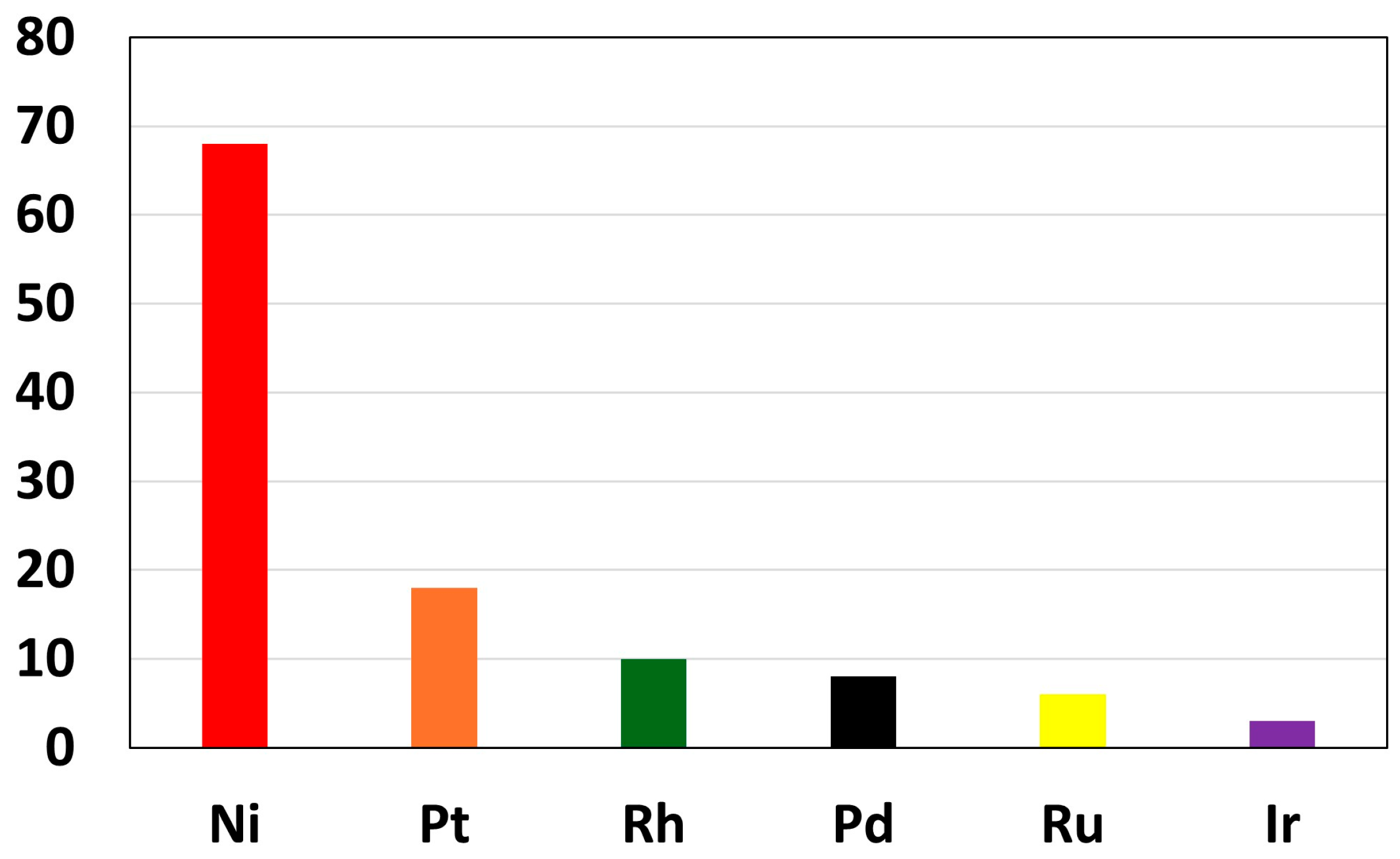
1.3. Traditional Catalyst Materials and Their Challenges

An ideal SMR catalyst should exhibit two properties, including hydrogen production with the online tracking of carbon dioxide and significant energy saving potential, together with a chemical nature that can affect catalyst performance. The most studied catalysts in the SMR reaction for the stability and prevention of active site sintering due to endothermic reactions must reduce carbon dioxide to provide maximum efficiency. However, the NiO particle size effect and how to control the process temperature in the fixed bed can be observed in Figure 11. Ni-based catalyst performance can be optimized by investigating the effect of different supports and promoters. It has been reported that considering the lower porosity of an electrode allows for the transport of desired ions to complete the separation of the optical and electrical components, providing a greater selection of materials and removing any problem regarding incompatibilities of the materials in the reactor to allow for the maximum production yield. Furthermore, the activity of Ni/MgAl2O4, Ni/ZnAl2O4, Ni/Al2O3, and Ni/SiO2 have been compared [18]. Ni/SiO2 is a well-known candidate for showing that methane decomposition is not favored under the reaction conditions leading to good dispersion of nickel, while Ni/ZnAl2O4 indicates that syngas is a key-intermediate in the chemical industry, with complete methane conversion at 500–600 °C, and it is considered ideal for SMR reactions due to its sufficient nickel content and the formation of Ce and Zr mixed oxides. The performance of Y-promoted Ni/Al2O3 catalysts was studied in the SMR process [19]. It was reported that carbon elimination from the surface of the catalysts prevents the closure of support pores, revealing the formation of a hollow structure in the supporting material. According to the results, a hollow Ni/alumina catalyst with yttrium particles reduces the temperature of the isothermal reactor to 600 °C and shows that the number of pores has increased compared to that noted in the unpromoted catalysts. It was concluded that a better dispersion of nickel active sites reduces the coke deposition on the used catalysts allowing for their participation in the SMR reaction.
Although nickel-based catalysts in the SMR reaction are mostly selective to syngas in the temperature range of 550–650 °C, ABO3 or A2BO4 are possible solutions, with high resistance to coking in both the partial oxidation and the dry reforming of methane (Figure 12). In the ABO3, perovskite structures, due to redox abilities and oxygen vacancy, can be employed in a wide range of catalytic reactions, releasing the corresponding perovskite structures, as well as the diffraction from NiO. Perovskite-type oxides show that hydrogen production from fossil-fuel sources such as natural gas/biogas (methane), coal, naphtha, and heavy oil remains a significant concern for this type of process [21].
Ding et al. employed a system consisting of a fuel reactor in such a CL-SMR process to study the bonding interaction between active sites [23]. The BaCoO3−ẟ/CeO2 catalyst was synthesized via a sol–gel technique and used in a pressurized fixed bed reactor to maintain stable syngas, and in the next process (FTS), syngas gas was employed for gas and liquid production at high pressure. It was reported that the nickel and cobalt perovskites resulted in the formation of hydrogen from a partial renewable source in an indirect manner and that there was a synergistic effect of ceria and BaCoO3−ẟ, noting that the noble metal catalysts can achieve good catalytic activity, indicating that the strong interaction between Co and Ni improves the dispersion of active components. It was indicated that in order for the gas production and hydrogen purity of perovskite help to oxidate CHx fragments adsorbed on Ni active sites and prevent carbon deposition on the catalyst for BaCoO3−ẟ, the temperatures should be higher than 850 °C, and the reaction temperature of 860 °C was used for the reaction time between the oxygen carrier and methane in POM stage. FESEM images confirmed that the most significant property of perovskite is its self-regeneration ability, suggesting that the steam cannot completely recover its lattice oxygen. Table 1 summarizes the related literature using perovskite catalysts for methane reforming.

1.4. Scope of Review

This review paper discusses the most attractive methods to produce hydrogen or syngas, including internal reforming in SOFCs. Additionally, major research results and challenges regarding the commercialization of SOFCs are discussed. In this review, advanced material and solid-state chemistry, highest hydrogen production efficiency, coking resistance mechanism, problems, and future perspectives for the potential to develop the so called “hydrogen economy” are also discussed.

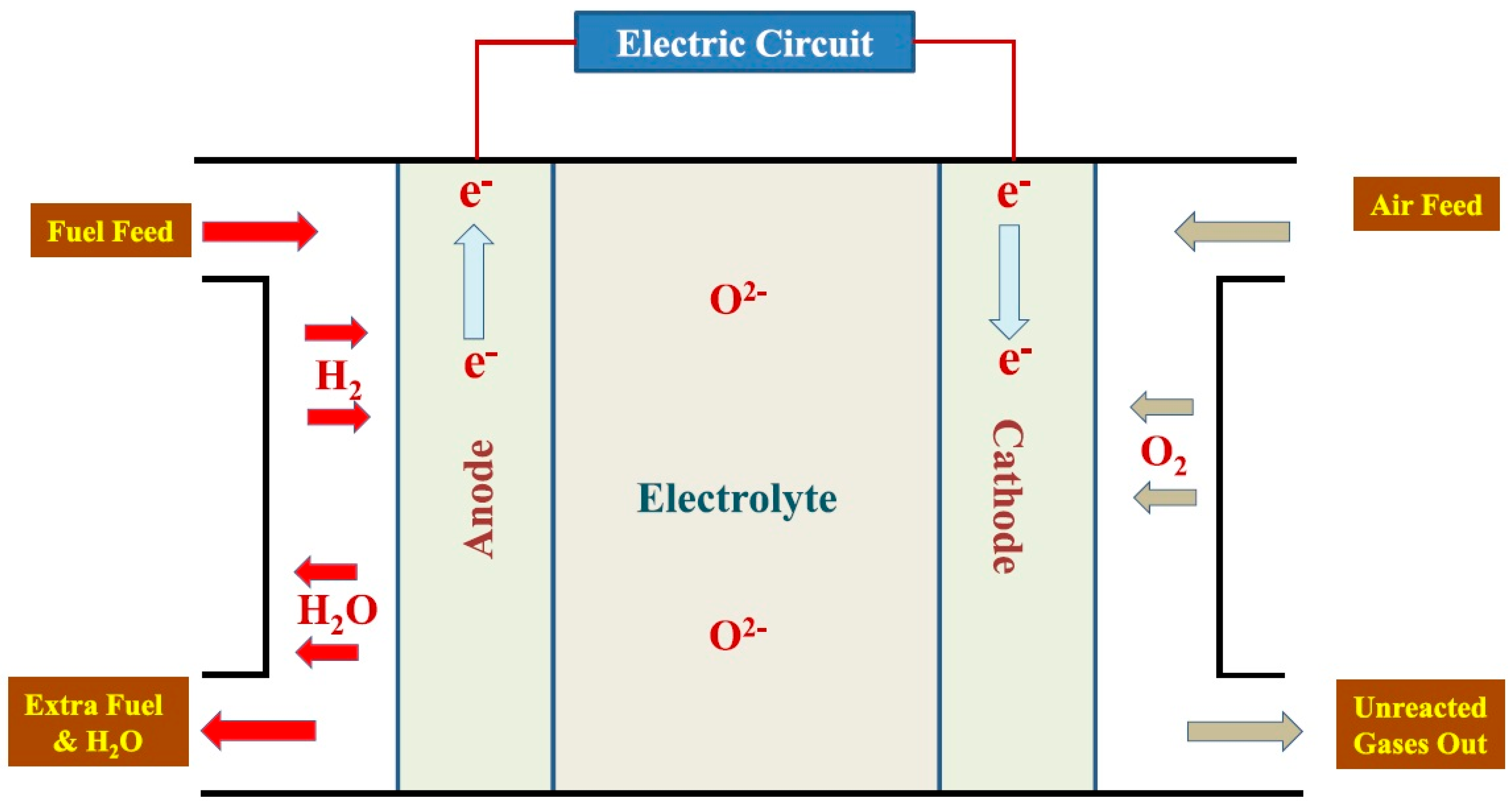
2. SOFCs Components and Functions

The SOFC consists of two porous electrodes and an electrolyte, with scorching operating temperatures of SOFCs (800–1000 °C). The elevated operating temperatures lead to the possibility of running the SOFC directly on practical hydrocarbon fuels, requiring no additional external layer or reforming unit. The fuel, which is usually gas, is catalytically converted to synthesis gas and then electrochemically oxidized to CO2 and water at the anode surface. A summary of the electrode reactions and overall cell reactions is as follows:
Anode :   H 2 + O 2 H 2 O + 2 e
C O + O 2 C O 2 + 2 e
Cathode :   O 2 + 4 e 2 O 2
Overall :   H 2 + C O + O 2 H 2 O + C O 2 + E
In general, the aim is preventing active nickel site sintering and providing sufficient electronic conductivity with two mobile ionic species, leading to a gasification process that delivers an output of a rough gas aimed at monitoring stable SOFC operations. On the other hand, the high operating temperature of SOFCs also provides excellent possibilities for feeding them into a gas turbine to produce additional electricity.

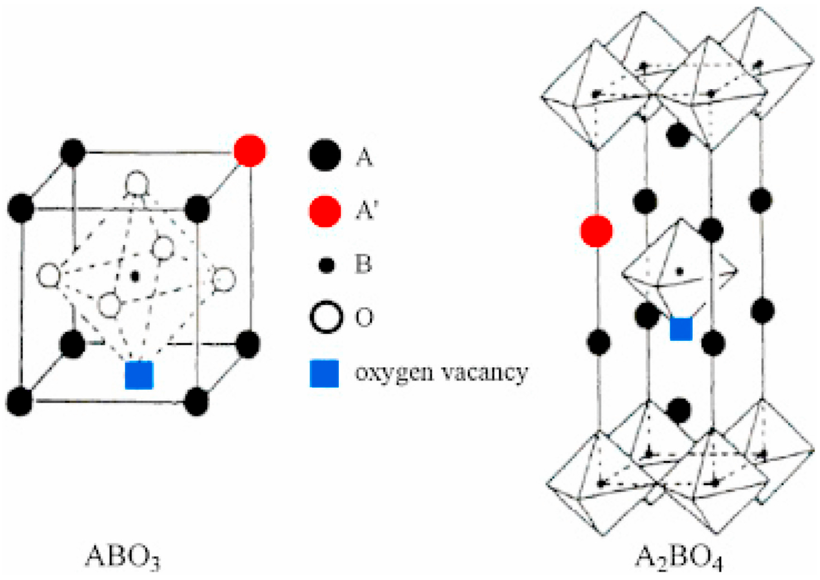
Anode Materials—Exploring Different Perovskites, Ruddlesden-Popper Oxides, Spinels, Etc.

Under optimized conditions, due to the oxidation of fuels, an anodic material must possess a high degree of electronic conductivity, sufficient electrocatalytic efficiency, and efficient thermal compatibility with other components in the cell. Due to their low electrode ohmic resistance and efficient electrochemical performance, pure metallic electrodes such as Ni, Pt, and Ru have been used as anodes. Niakolas reviewed the progress on modified anode materials to prevent sulfur formation and applied the internal reforming and oxidation reactions of methane in SOFCs [28]. The Ni-based electrodes suffer from carbon deposition leading to direct structural damage, low tolerance to poisoning from sulfur components, poor redox stability, and sintering after prolonged fuel cell operation. It was found that the modification of NiO/GDC anode powder by Au nanoparticles improved catalytic and electrocatalytic activity for the reaction of internal methane steam reforming. Chen et al. confirmed decreasing carbon deposition on the SOFC anode via using Ni-yttria-stabilized zirconia (Ni-YSZ) with a samaria-doped ceria (SDC) catalyst layer [29]. A substantial performance improvement towards methane reforming and the electrode activity were achieved when SDC was used as the electrolyte, coated by a catalyst layer. It was found that SDC nanoparticles on a nickel-based composite exhibited promise for the SMR reaction of methane and prevented coke formation via the application of oxidizing agents such as CO2 and steam. In the SOFC, at the fuel side metal anode, there is no stress material of choice for SOFC manufacture, and this limits the choices to Ni, Co, and the noble metals. Additionally, the anode must display a porous structure at high operating temperatures, generally reducing the growth rate of the oxide by a factor of ten. It was reported that the variation in thermal expansion coefficients leads to enhanced sintering of the nickel at higher temperatures [30]. Table 2 compares the electrochemical performance of SOFCs using different anodic systems.
Clean and efficient energy conversion can provide electric energy with higher efficiency for high-temperature applications owing to their inherent presence in the fuel. Perovskite oxides, such as titanates and chromites, owing to their high oxygen mobility and tunable electronics, are considered as alternatives to metal ceria-based systems. Double-perovskite Sr2MgMoO6 showed high activity and long-term stability for high activity methane conversion. However, due to their catalytic activity and high oxygen vacancy concentration, double perovskite anodes are used in catalytic combustion, showing an efficient method of hydrogen production in a clean pathway [47].

Structure–Property Relationship (Ionic and Electronic Conductivity, Thermal Expansion Coefficient, Acidity/Basicity)

SOFCs are energy harvesting systems, requiring the use of no pricey catalysts, including Pt. On the other hand, in contrast to the lower capital costs associated with the SOFC operating temperature, this method displays some disadvantages, including material degradation over time, difficulty managing the water vapor and fuel utilization ratio, the bulky design, and the thermal insulation requirements, which result in an increase in the overall cost of the cell. Addressing the challenges of SOFCs involves a combination of material science advancements, engineering innovations, and operational optimizations. However, a reduction in the operating temperature decreases the electrochemical reactions at the electrodes. Thus, material selection is important, due to the performance of SOFC single cells. The material should provide some of the significant properties depicted in Figure 13 to be considered as a cathode or anode material for SOFCs. Different catalyst preparation techniques are used to prepare NiO–SDC composite anode oxide materials, and their properties are crucial for the cell’s efficiency. The anode facilitates the oxidation of fuel and should possess catalytic activity. The cathode catalyzes the reduction of oxygen and should show a compatible thermal expansion coefficient with that of the electrolyte. The coefficient of thermal expansion (CTE) causes thermal gradients that disturb its phase-matching properties. During heating and cooling cycles, mismatched CTE values between components (anode, cathode, electrolyte, and interconnect) can cause mechanical failure due to thermal stress. Porosity directly influences the extent of TPB by determining how effectively the gas phase can diffuse through the electrode and reach the active sites. Pores need to be large enough to allow for gas diffusion but small enough to ensure sufficient contact between the electrolyte and electrode particles. Higher porosity reduces the particle–particle contact area, decreasing the electronic/ionic conductivity but increasing gas access to the TPB. Additionally, long-term operation can cause the sintering of particles, reducing porosity and active TPB length. TPB length per unit volume can be estimated by improving the porosity of TPB, particle size, and packing geometry using theoretical models or microstructural simulations. Studies show that the TPB length peaks at intermediate porosities (~30–40%) for most SOFC electrodes.
Unlike traditional cathodes that rely on electronic conduction alone, mixed ionic–electronic conduction (MIEC) materials can conduct both ions and electrons, which significantly enhances the oxygen reduction reaction (ORR) kinetics. This phenomenon is commonly observed in the perovskite-structured (ABO3) composites [49]. The A-site and B-site in the perovskite ABO3 structure play critical roles in estimating the properties of perovskite oxides and the ionic conductivity of the material. These properties are crucial for applications like SOFCs, where oxygen ion transport is fundamental. The interplay between A-site and B-site cations determines the overall behavior of the perovskite. Different mixed conducting materials such as Ba0.5Sr0.5Co0.8Fe0.2O3−ẟ (BSCF), La0.6Sr0.4Co0.2Fe0.8O3−ẟ (LSCF), La1−xSrxGa1−yMgyO3−ẟ, solid solutions of LaMnO3 doped with LaCoO3, LaCrO3, and La1−xSrxCuO3−ẟ corresponding to the unutilized part of the cathode are employed for the reduction in O2 [50].
Although the common nickel-based anode catalysts show excellent catalytic activity for fuel oxidation, as well as electronic conductivity, these materials also have their disadvantages. When hydrocarbon fuels (methane) are used, nickel promotes carbon deposition due to its high activity for methane cracking [51], and the formation of nickel sulfide reduces catalytic activity and causes irreversible degradation, which then results in the cracking and delamination of the anode–electrolyte interface. While desulfurization and material modifications can mitigate these effects, advancements in sulfur-tolerant materials and anode designs are essential for reliable operation in sulfur-contaminated fuels. However, it is interesting to develop new, alternative anode catalysts that show similar catalyst performance to that of nickel and exhibit a high stability during long-term reactions. MIEC perovskites extend the reaction zone to the entire surface of the anode by enabling oxygen ion diffusion and electronic conductivity throughout the material [52]. MIEC perovskites often contain a high concentration of oxygen vacancies that promote the adsorption of hydrocarbons. Additionally, transition metals at the B-site are redox-active and facilitate O–O bond breaking, forming reactions that replace the peroxide [53].

3. Mechanistic and Kinetic Studies of Common Reforming Processes

The burning of fossil fuels has long been a dominant global energy source. The study of dry reforming reaction for syngas production is an important area of research that offers the potential for both greenhouse gas reduction and the creation of sustainable energy sources and chemicals. An attractive approach for reducing CO2 levels is using steam reforming of methane during the transition stage of moving from a carbon-based to a carbon-free program; this method has also been seen as promising for the production rate of syngas. Hydrogen production technologies differ regarding the state of development, and the steam methane reforming (SMR), dry methane reforming (DMR), bi-reforming of methane (BRM), and partial oxidation of methane (POM) are compared in Table 3 to show the relationship between hydrogen yield and stability in the endothermic reactions. SRM
Many studies involve the capture of CO2 and the utilization of renewable energy, considering general agreement on first-order kinetics with respect to CH4 and the possibility of diffusional limitations. Kim et al. investigated conventional steam reforming for reduced carbonization and good dispersion over a Ni/γ-Al2O3 to develop small stationary reformers [54]. It was reported that the activation energies are dependent on nickel particle size in the catalyst pores. The authors used the effect of steam in the SMR reaction based on the entire volume to ignore the internal diffusion effects. To investigate the reaction of methane and steam inside the reactor catalyst, the SMR reaction was conducted over a range of temperatures with a constant feed ratio. Since the methane conversion did not change significantly as a result of increasing the flow rates of the reactants, the external diffusional limitations could be safely ignored. It was found that the rate of thermal energy generation due to chemical reaction relative to the rate of packing density (carbon monoxide and carbon dioxide) clearly predict the number and size of nickel metal particles in the Ni/γ-Al2O3 catalysts. It was concluded that the use of nickel-based catalysts has received significant attention in recent years because it was strongly related to the nickel loading in the catalyst due to the collision density. Zeppieri et al. studied the kinetics of the methane steam reforming reaction according to experimental data for the methane conversion reactions to minimize coke formation in the temperature range of 723–1023 K [55]. They fitted the experimental data using CH bond-breaking to achieve rate-limiting for both methane and the catalytic oxidative coupling of methane, which can enhance the bonding of C–H bonds after introducing methane and its effects on the activation energy. In the reaction mechanism, the cleavage of C–H bonds was a slow step, and the decomposition of CHxO (x = 1–2) into CO gas and adsorbed H species on the catalyst equaled the RDS in the reforming reaction. As a result, the forward rates are not affected by the carbon monoxide and hydrogen concentrations, the formation of carbon at the surface of the nickel particle embedded in the support, and the lifting of the nickel, which differ drastically from those of the whisker-type carbon formed from CO dissociation. The average values of activation energy were studies, along with the reaction kinetics of a wide range of stoichiometric reactions using different rate limiting steps, which were measured against the geometries from gas-phase experiments to validate the predictive power of the resulting models. Finally, the activation energy values were validated for rhodium-perovskite catalyst using density functional theory calculations, considering the non-homogeneity of the comparison.

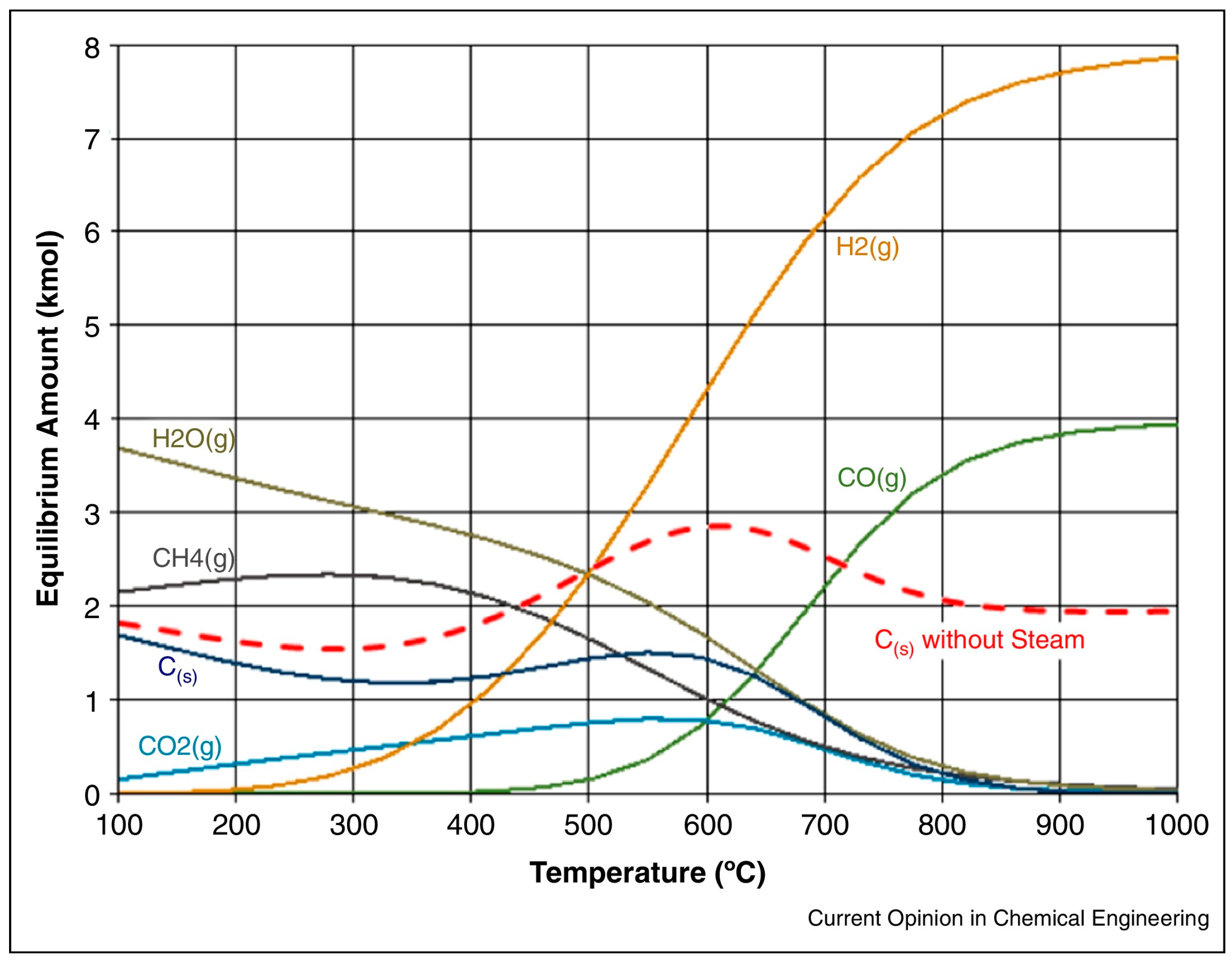
3.1. Steam Methane Reforming

SMR consists of strong endothermic and mildly exothermic reactions.
C H 4 + H 2 O C O + 3 H 2 H 298 = 206 k J / m o l C H 4 + 2 H 2 O C O 2 + 4 H 2 H 298 = 164.9 k J / m o l C O + H 2 O C O 2 + H 2 H 298 = 41 k J / m o l
Steam reforming catalysts include the common commercial copper-based steam reforming catalysts, providing the basic parameters to produce syngas and hydrogen. Ni-based catalysts are common materials for use as promising catalysts, exhibiting a lower cost and limiting the typical problems of SMR and their coking resistance, and these benefits can be enhanced by using supporting materials such as perovskites. SRM suffers from high energy consumption, harsh reaction conditions, and low process stability [56]. On the other hand, SRM coproduces CO2 due to WGS which leads to a strong greenhouse effect and its handling in the manufacturing of chemicals, which include ammonia and methanol. The common types of catalysts used in different steam methane reforming of hydrocarbons are listed in Table 4.

3.2. Partial Oxidation of Methane for H2 Production

Methane total and partial combustion generate CO2, H2O, and syngas, as indicated below:
C H 4 + 2 O 2 C O 2 + 2 H 2 O H 0 = 802.3 k J m o l
C H 4 + 1 2 O 2 C O + 2 H 2 H 0 = 36 k J m o l
Syngas is typically produced, since it uses C5+ hydrocarbon production to decrease carbon deposition on the catalyst surface in the main reformer, ensuring high catalytic activity for the development of future nickel-based catalysts for SMR and DMR reactions (Figure 14). In the partial oxidation of methane (POM), syngas is generated with a H2/CO ratio of around two, which is proper for solid oxide fuel cells. The most investigated catalysts for POM are transition metals (nickel, cobalt, and iron), noble metals, and perovskite oxides with different oxidation states. Compared to the traditional syngas production, the solid oxide co-electrolysis technique can influence the effects of the structure and oxidation state of the metal via changes in the particle size. In 2023 Hasanat et al. reported reactant concentrations on the nickel-based catalyst that used two basic substrates [60]. The results indicated that active metal affects catalytic performance, and active metal Ni has been reported as a very active metal for the DMR, improving the syngas ratio from 1.4 to 2.0. It was suggested that the fact that the increase in surface area improved the catalytic activities may be due to the formation of a porous and large surface area by enhancing the accessibility of the catalytic surfaces to react between its surface groups and water molecules for gas adsorption. Analysis of the spent catalysts showed a promising route for converting biomass into syngas, leading to the formation of amorphous carbon, which is easily converted into CO, increasing syngas production.
Table 5 summarizes the different catalyst systems with varying metal oxidation states for POM to produce fuel-rich syngas.

3.3. CO2 Reforming of Methane for H2 Production

The costs related to the separation of carbon dioxide from methane are high, and the CO2 reforming of methane is a promising alternative for producing value-added chemicals, including synthesis gas and liquid fuels. This process is called dry methane reforming (DMR), and one of the main challenges of DMR is the catalyst deactivation that occurs owing to carbon deposition during the high temperature reaction [67]. Recent studies have concentrated on developing catalysts (using different types of metal and supports) that reduce the rate of CH4 decomposition and/or CO disproportion. On the other hand, it was reported that the promoted catalysts show lower carbon deposition and longer stability in DMR. Kurdi et al. investigated hydrogen production via DMR on 5Ni/ZrO2 catalysts at 700 °C [68]. Their results confirmed that Sr as a promoter improved the activity to 62% on the 5Ni15YSZ catalyst. In addition, increasing the Y2O3 modifier enhanced catalytic performance and hydrogen yield and decreased carbon formation. In another study, hydrogen production via dry reforming of CH4 was studied over a ZrO2-doped Ni/ZSM-5 nanostructured catalyst at 850 °C [69]. The results revealed that the surface of the catalysts behaved as identical catalytic sites for the formation of CH4. Based on the obtained results, the addition of Ni (8%) and ZrO2 (5%) to the catalyst should make an additional contribution to the original nickel ensembles, providing higher activity than the other ZrO2-promoted nanocatalysts. Using this method, it seems that the deposition of carbon dioxide might be speeding up greatly, decreasing carbon deposition. Sajjadi et al. investigated the effect of methane conversion and the Ni/La2O3 catalyst deactivation rate from coke [70]. They concluded that Ni-Co/Al2O3 showed a high syngas ratio (1.02) and stable conversion over 1440 min owing to the synergistic effect of the catalyst preparation method. It should be noted that a traditional sol–gel method, followed by impregnation with the addition of small amounts of Co to Fe, resulted in carbon accumulation and improved the stability of the catalyst. Additionally, the production of hydrogen from steam methane reforming depends on the operating conditions and on the desired specifications of the effluent streams in comparison with the nanocatalyst prepared through the impregnation technique.

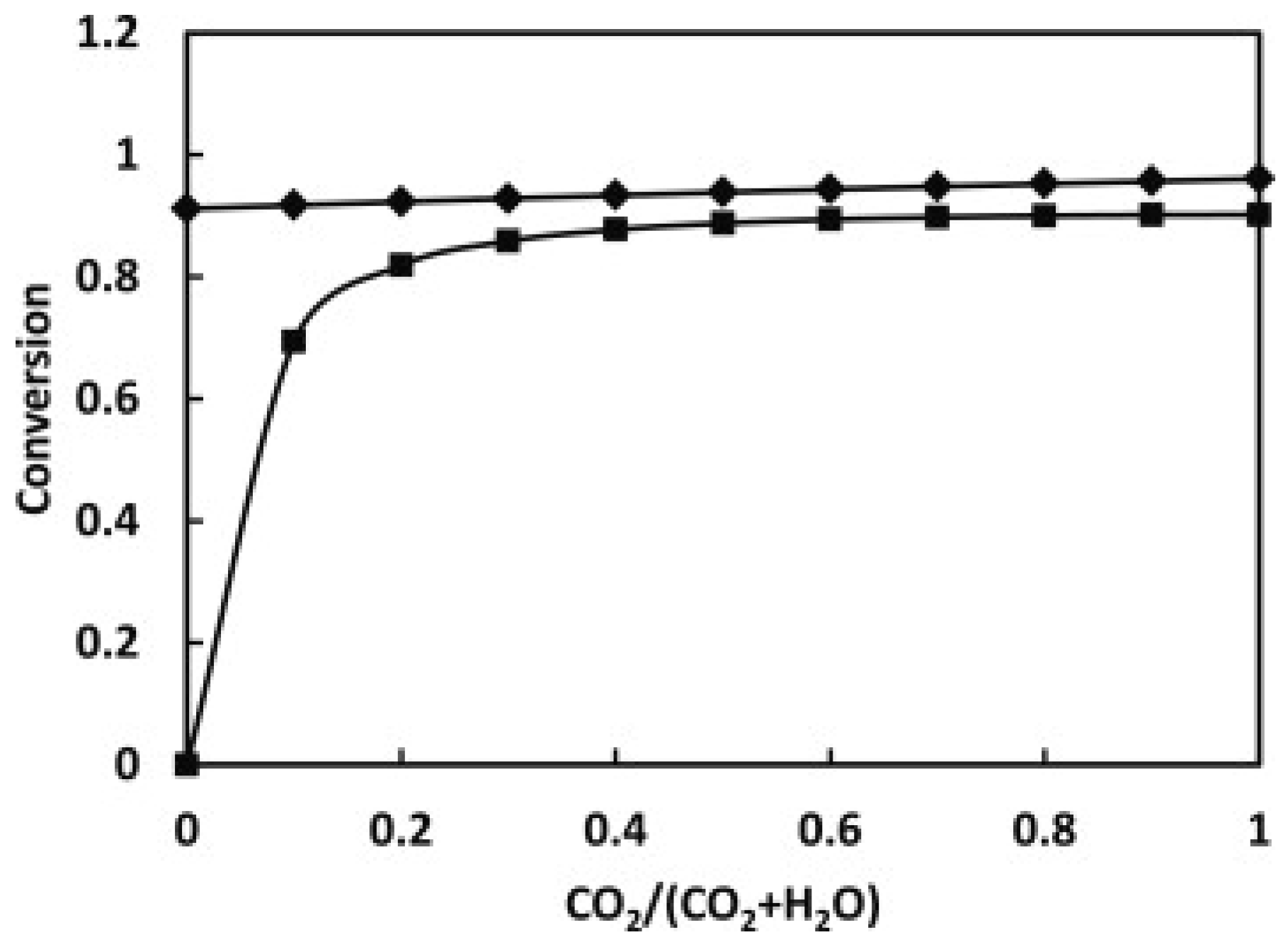
3.4. Mixed Steam and Dry Reforming

Bi-reforming of methane (BRM) to produce syngas is performed at atmospheric pressure if methane, carbon dioxide, and water react in the most desired way, with a proper ratio of hydrogen to carbon monoxide that avoids the additional costs required for biogas upgrading through biological CO2 removal and conversion. Noble metals such as Ru, Pd, Pt, Ru, and Rh, together with nickel and cobalt, are the preferred types because of their high specific activity, resistance to deactivation, and the recovery of precious metals from spent refinery catalysts. The BRM reaction involves several reactions that influence the elementary reaction network.
ReactionStoichiometry H 298 K 0 ( k J m o l 1 )
BRM 3 C H 4 + C O 2 + 2 H 2 O 4 C O + 8 H 2 712
SMR C H 4 + H 2 O C O + 3 H 2 206
DMR C H 4 + C O 2 2 C O + 2 H 2 247
WGSR C O + H 2 O C O 2 + H 2 −41
WGS C O 2 + H 2 C O + H 2 O 41
CH4 dissociation C H 4 C + 2 H 2 75
Boudouard reaction 2 C O C + C O 2 −172
The BRM is a complex reaction and a substitute process for producing syngas to reduce carbonization and allow for the best combination of coking prevention. Kumar et al. determined the equilibrium composition of the BRM reaction, which can control the syngas ratio at the end by regulating the reaction temperature, as well as the contemporary catalytic materials (Figure 15), to demonstrate that the greater the amount of undesired CO2 produced during the reaction, the larger the final crystal size, especially for generating green and sustainable energy sources [71].
The choice of a catalyst is critical in determining SMR conversion. Both the active metal component and the catalyst support play a crucial role in determining how well methane is reformed into syngas, hydrogen, or other products. Nickel catalysts are commonly used in reforming reactions due to the production of NiO particles and their durability during the gas reforming reactions. The stability of the catalyst can be improved by selecting the proper support materials to prevent the poisoning of the catalyst. Table 6 provides the catalysts exhibiting high activity in the BRM reaction, developing a novel catalyst capable of high activity.

4. Catalyst Deactivation Mechanisms

The stability of catalysts in reactions, especially in complex processes like methane reforming or fuel-cell operation, is crucial for maintaining high activity and long operational life. Poisoning by sulfur and coking lead to the deactivation and regeneration for reforming and partial oxidation catalysts. Table 7 lists the relationships between the type of catalyst and the deactivation chemical reaction occurring via the recombination of both volatile and non-volatile radical components.

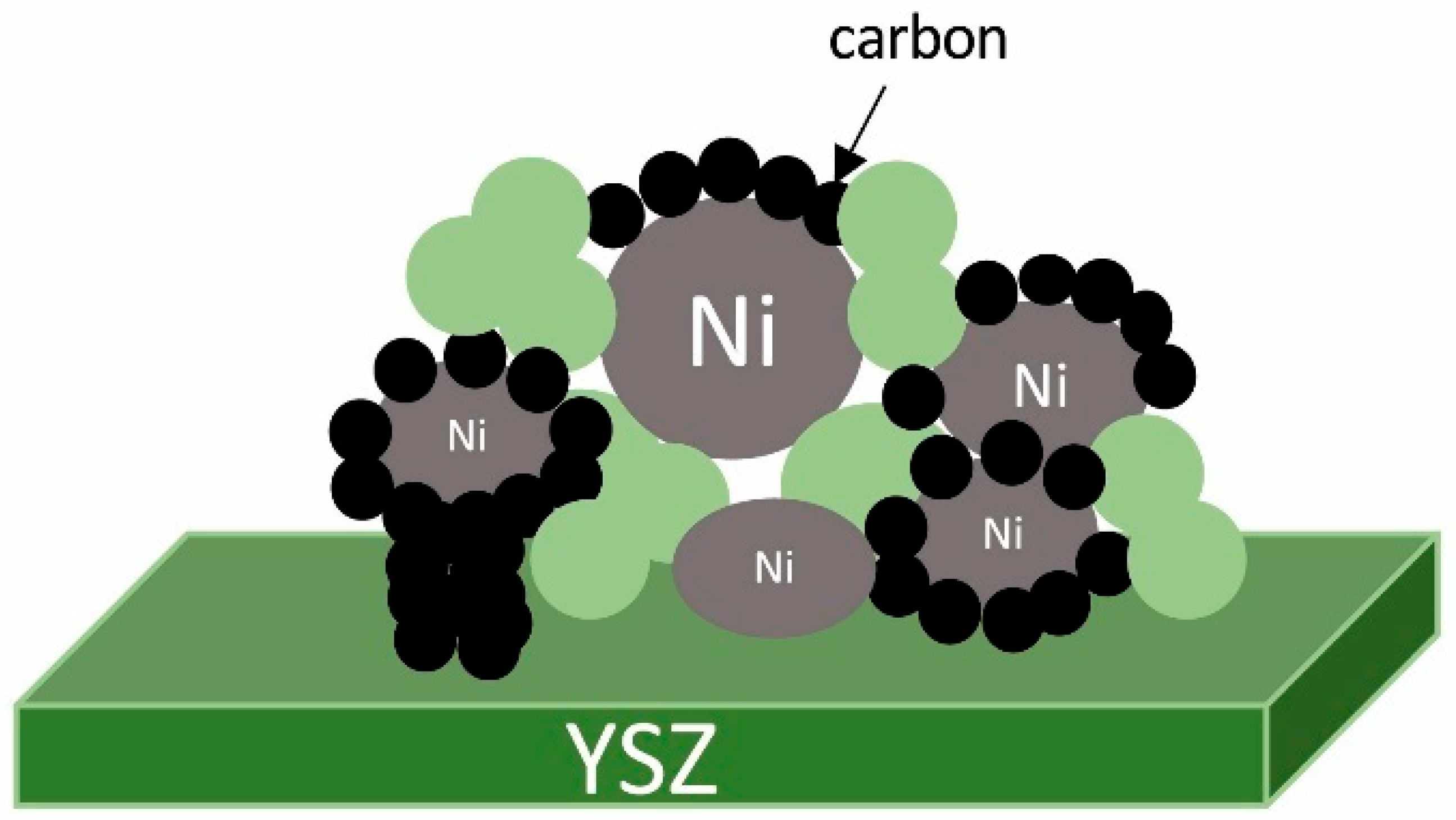
4.1. Carbon Formation

In methane reforming, solid carbon deposition leads to blockage of the active sites, allowing for the comparison of the ideal thermodynamic limitations and the actual reaction rate of methane reforming via the following reactions:
ReactionStoichiometry H 298 0 ( k J m o l )
Methane cracking C H 4 C + 2 H 2 74.9
Boudouard reaction 2 C O C + C O 2 −172.2
Steam gasification of carbon C + H 2 O C O + H 2 131.4
Carbon dioxide gasification of carbon C + C O 2 2 C O 172.2
Water–Gas shift C O + H 2 O H 2 + C O 2 −41.0
Complete carbon oxidation C + O 2 C O 2 −393.7
Solid carbon deposits on the surface of the catalyst, including carbolic carbon, amorphous carbon, and graphitic carbon, can cover active sites by blocking the pores of the catalysts and preventing carbon bonding at the active sites [76].
It was reported that the conventional alumina-supported nickel-based catalyst showed higher activity than those prepared at low calcination temperatures, with potential for applications involving high temperature owing to their thermal stability [77].

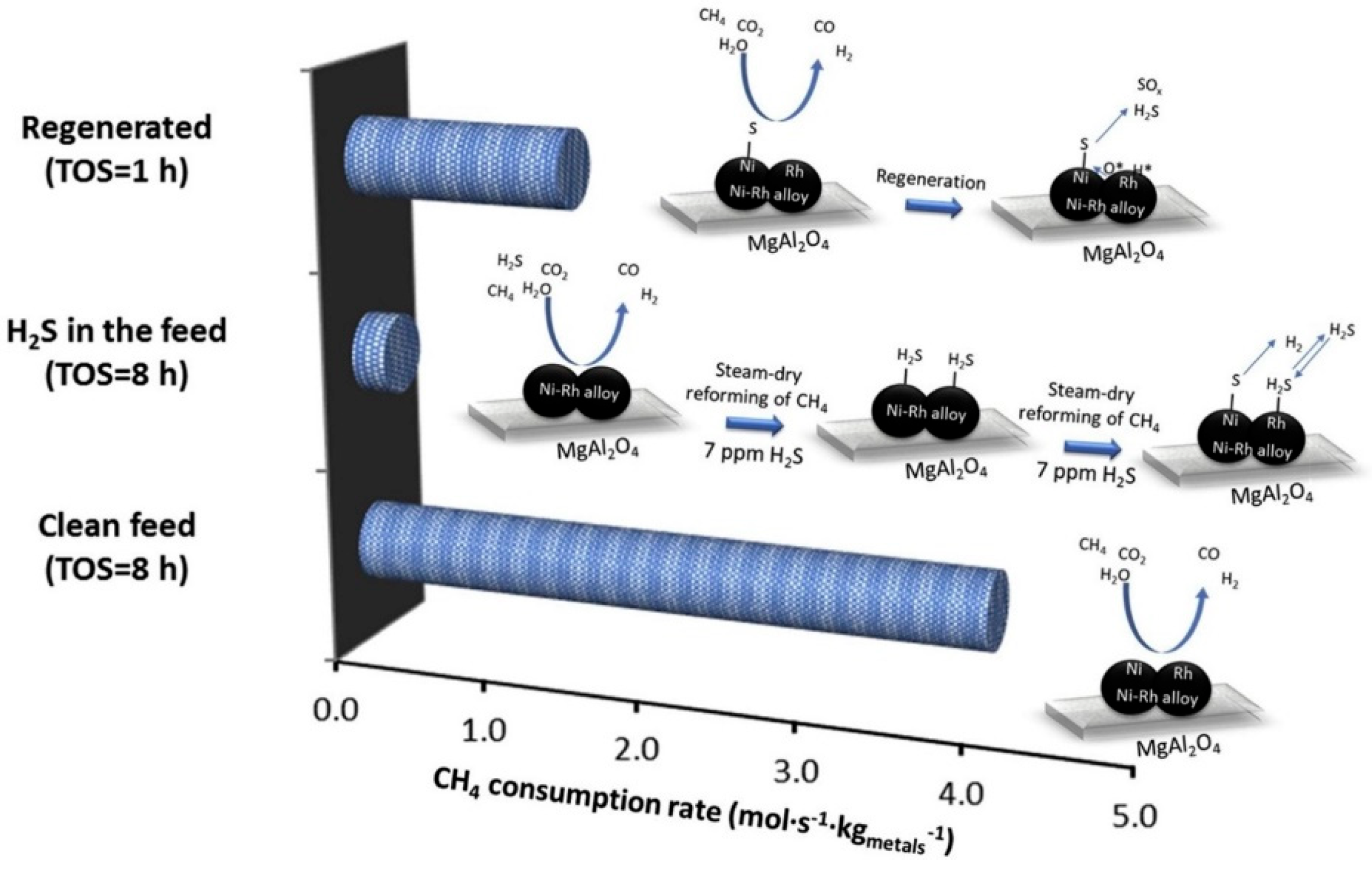
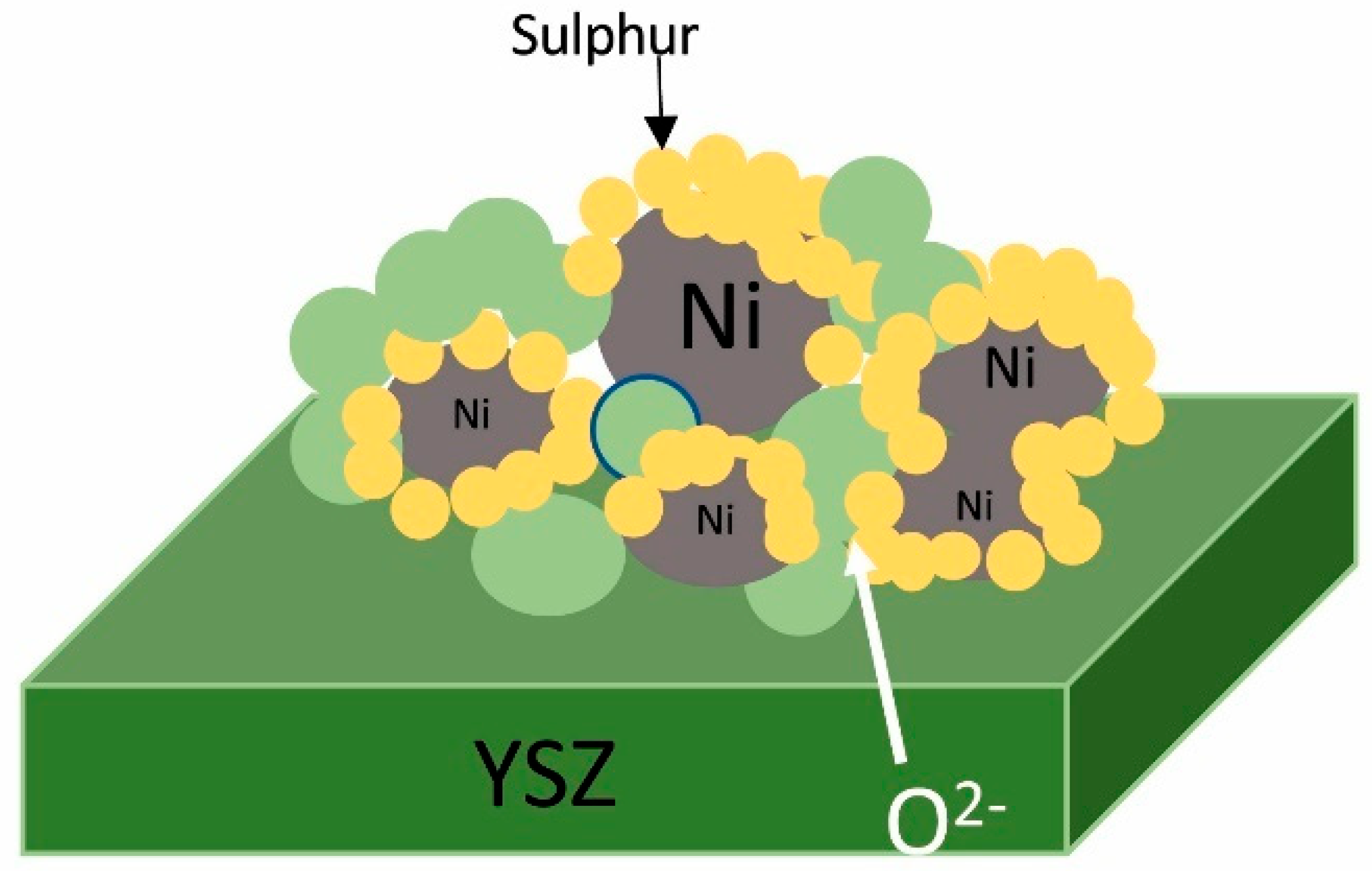
4.2. Metal Sulfide Formation

Catalyst poisoning in methane reforming involves the irreversible adsorption of poisonous species onto the metal of the catalyst, which effectively blocks the reactant gases from reaching the metal sites. This leads to a decrease in the overall catalytic performance, elucidating that key relationships increase the amount of carbon deposition reduction as the crystal size decreases. In the investigation of sulfur poisoning caused by adding metal additives and creating sacrifice sites, Ni–Rh catalysts supported on MgAl2O4 (Figure 16) were designed to improve the H2S tolerance [78]. The introduction of hydrogen sulfide into the feedstock led to an almost 90% decrease in the methane consumption rate compared to that for the clean feed. It was concluded that the Rh concentration in Ni–Rh catalysts plays a pivotal role in determining the regeneration ability, since nickel and Ru are two common SMR active sites, and the optimization of the loading amount is a keen research area for maximizing SMR efficiency.
Gallego et al. investigated a LaNiO3 perovskite structure during reforming reaction poisoning by hydrogen sulfide in a range of 0–250 ppm [79]. Catalyst performance confirmed that the reactions with and without hydrogen sulfide (12.5 ppm) are very promising for the steam reforming of natural gas, showing minimum level of coke formation. After 8 h of reaction, the H2S concentration produces promising metal dispersion and displays a better redox and synergistic effect and amounted to a nearly 20% lanthanum oxysulfide phase formation, which is thermodynamically more favorable in the reaction atmosphere under microwave heating. It was concluded that although the LaNiO3 perovskite catalysts show promising coke-resistant properties, their tolerance to sulfur poisoning can be improved by modifying the B site of perovskite.
In another research study the effectiveness and the deactivating of catalysts was investigated through varying the operating temperature and the H2S concentration [74]. Various concentrations of H2S tested on the nickel-based catalysts, with a cerium additive, during the steam reforming of biogas. It was reported that no characteristic peaks assigned to NiS and Ni3S2 were found in the spent poisoned catalyst. Additionally, the effects of the sulfur poisoning on the activity at 700 °C lead to saturation coverage at three different concentrations of H2S (30, 100, and 150 ppm). On the other hand, the catalyst activity indicated that the sulfur removal increased by enhancing the reaction temperature to be consistent with the steady-state activity for 150 pm H2S at 800 °C. It was concluded that the residual trace levels of sulfide adsorbed more strongly at lower operating temperatures, and nickel particles on the surface of the catalysts display an average particle size of 12 nm.

5. Methane Reforming and Partial Oxidation Catalysts for SOFCs

The hydrogen economy refers to the use of H2 as a clean and efficient fuel to replace fossil fuels in various applications, such as electricity generation, transportation, and industrial processes. In some cases, the methane reforming process can be conducted outside the fuel cell stack in an external reformer. This process typically involves converting methane into syngas using various processes. One of the significant advantages of SOFCs in the conversion of methane is that they emit far fewer pollutants than do conventional combustion-based systems. SOFCs operate on the principle of solid-state electrochemistry, where oxygen ions are transported through a solid electrolyte or other ceramics from the cathode to the anode. SOFCs are known for their high electrical efficiency, often reaching levels of around 60–70%. However, when they are used in combined heat and power (CHP) applications, the reaction performance can rise significantly, up to 90%. Carbon-based fuels can be converted into syngas using several reforming techniques, including steam (steam reforming), carbon dioxide (dry reforming) or limited oxygen (partial oxidation).
C H 4 + H 2 O 3 H 2 + C O
C H 4 + C O 2 2 H 2 + 2 C O
C H 4 + 1 2 O 2 2 H 2 + C O
The exothermic nature of partial oxidation reforming (POX) makes it the least energy-intensive of the reforming reactions, but a perennial problem with this approach is the tendency to yield complete or total oxidation (7) or to deposit carbon through methane pyrolysis.
C H 4 + 2 O 2 2 H 2 O + C O 2
C H 4 C + 2 H 2
The catalytic and/or electrocatalytic oxidation of methane suffers from low energy efficiency, it there is currently no information available regarding surface reaction enhancement by plasma, which facilitates the reforming of methane into hydrogen and carbon monoxide. High operating temperatures are required for efficient methane reforming and oxidation, which can limit material durability. Carbon forms on the anode’s catalytic surface, particularly on nickel-based catalysts, which can block the active sites, degrade catalyst performance, and ultimately reduce the cell’s efficiency and lifespan. Internal steam reforming is a strategy used in SOFCs to convert hydrocarbon fuels like methane into syngas directly at the anode, which leads to an open circuit voltage (OCV) loss, owing to air leakage. Table 8 shows the possible electrochemical reactions under direct or gradual internal reforming within the SOFC anode [80].
Methane can decompose on the catalyst surface, typically occurring close to an equilibrated reactor outlet, where methane is partially oxidized using oxygen to produce syngas. Since lattice oxygen plays a crucial role in the removal of adsorbed carbon during catalytic processes, it can be inferred that oxygen leads to better temperature distribution in the kinetics of methane partial oxidation. However, the CPOX approach reformulates hydrocarbons into CO and H2, which are the primary fuel for SOFC electrochemical reactions. Lee et al. studied direct methane fueled SOFCs based on catalytic partial oxidation and suggested an efficient integration of the reforming reactions by CPOX. It should be noted that the incomplete supply of reactants or the accumulation of products increases polarization. When only methane is fed to the anode, the hydrocarbon fuel adsorbs onto the anode catalyst surface, as shown below:
C H 4 + 4 O 2 C O 2 + 2 H 2 O + 8 e
On the other hand, the simultaneous supply of O2 to the nickel anodes results in the CPOX of methane by the formation of syngas, as expressed below:
C H 4 + 1 / 2 O 2 2 H 2 + C O
Under CPOX conditions, Ni–YSZ demonstrate promising power densities of 0.27 Wcm−2 at 650 °C, with the efficient utilization of hydrocarbon fuels of 0.33 and 0.26 Wcm−2, calculated for hydrogen and methane feeds, respectively. GDC provides excellent oxygen ion conductivity at intermediate temperatures, which supports the electrochemical oxidation of syngas produced by CPOX. It was concluded that the Ni–YSZ anode-supported cells used in the POM reaction has a strong influence on the degradation of the electrochemical and catalytic performance, showing high stability and performance by oxidizing coke during the reaction. On the contrary, the DMR reaction leads to a low syngas ratio, and coke formation can be reduced by using a single atom catalyst, which is related to the synergistic effect between carbon and metal. The XAS result confirms that YSZ used as an electrolyte between the catalyst and the buffer layers prevents chemical reduction and reveals that GDC exhibits a higher concentration of oxygen vacancies than does YSZ due to its lower enthalpy of oxygen vacancy formation.
In another study, a novel perovskite-based catalyst facilitated lattice oxygen participation in the POM process, reducing the dependence on molecular oxygen. The incorporation of nickel into strontium zirconate adopts a perovskite structure, while the formula ABX3 may form separate catalytic nanoparticles when exsolved under reducing conditions. The reaction profile confirms that with a sudden change under a reducing atmosphere, some nickel ions migrate to the surface and form highly dispersed metallic nanoparticles, leaving vacancies in the perovskite lattice. It was noted that replacing the zirconium with hafnium yields notable effects on the activity in the POM reaction. Based on post-reaction temperature programmed oxidation, Hf substitution may result in lower CO selectivity because of reduced lattice oxygen availability, potentially leading to incomplete methane conversion. It was concluded that at 900 °C, there is some degradation attributed to the stronger Hf–O bonds, which prevent excessive reduction in the catalyst and inhibit carbon formation. Supported Ni catalysts can form nanoclusters on the perovskite surface, which can either enhance or inhibit catalytic activity, depending on the size and distribution of the clusters.
Elkharouf et al. used Ni@SiO2 catalysts for the indirect internal reforming (IIR) of CH4 by combining the two reactions. The TEM images obtained showed that the NiO catalyst coated with a silica support potentially influenced the reduction behavior of NiO to metallic nickel. The NiO@SiO2 catalyst facilitated the reduction of NiO to Ni by providing a heterogeneous interface that promotes electron transfer and access to reducing species, all in the range of 300–525 °C. It has been reported that textural properties of the NiO–SiO2 hybrid materials exhibited a typical type-IV isotherm, and it can help distinguish metallic nickel from its oxidized form, remaining at angle 37°, 47°, and 63°. The Ni@SiO2 catalyst did not show that pretreatment for the catalytic activity enhanced the hydrogen-based selectivity, and the CO conversion rises for WGS owing heat loss during of the biogas dry reforming reaction. The resulting high methane conversion shows Ni@SiO2 to be a viable catalyst which can maintain its structure at the high reaction temperatures required for the partial oxidation process. It was concluded that the silica shell can indeed influence the electrical resistivity of the NiO@SiO2 during the pretreatment step. In addition, the prepared Ni@SiO2 catalyst showed high stability, without any noticeable decline in the catalytic activity during the reaction, leading to the preservation of the catalytic efficiency at high temperatures, but it could also increase the resistivity due to the insulating nature of the silica shell.
Larrondo et al. studied POM over synthesized Ni/Ce0.9Zr0.1O2 catalysts using the gel–combustion route. It was reported that above 650 °C, due to the formation of a dense iron layer, the pre-treatment atmosphere has the same effect. It is important to note that the Ce0.9Zr0.1O2 has shown stable performance as a methane total-oxidation catalyst at intermediate temperatures. Above 650 °C, the solids exhibit the unwanted formation of products of total oxidation for the internal reforming of methane, which act as active sites, with a H2/CO ratio of 2/1.
Zhan et al. used La4Sr8Ti12O38 perovskite in SOFCs for catalytic POM in an oxygen-permeable membrane reactor. The reaction mechanism demonstrated good steam reforming activity, differing from the conventional steam reforming process, showing a direct methane partial oxidation route below 800 °C and obvious CO2 and steam reforming activities above 850 °C. It was concluded that the catalytic properties are strongly impacted by both the reaction temperature and the methane feed rate or O2/CH4 ratio.
Sengodan et al. reviewed the catalytic activity, covering the catalytic reforming for hydrogen production via the development of a more stable catalyst capable of providing high hydrogen yield. It was reported that the key catalyst parameters, including the electronic effect of alkali atoms, reactant concentration, reactor design, and feed and inert gas flow rates, will be stopped and an optimum performance obtained by the regulation of the operating conditions. The promoted nickel-based catalysts include cobalt, copper, platinum, manganese, ruthenium, and gold, and the study addresses the limitations of nickel catalysts, such as coking and strategies to improve hydrogen production, including bimetallic and multimetallic catalysts.
In another study, the inner grain boundaries of doped ceria were shown to enhance the accessible active sites for OER reaction on NiO/CeO2-δ-YSZ anodes for IT–SOFCs applications. Additionally, the effect of nickel and cerium infiltration on the yttria-stabilized zirconia (YSZ) structure and its textural properties leads to the use of cheap transition metals (usually Ni/Co) as the base and noble metals, which are involved in FTS to obtain aliphatic products, as promoters. It was concluded that the increase in the cerium as a promoter, as well as anode powder coarsening, should promote the transformation of the structure at the surface and reinforcing the Ni-rich interface structure, showing the porous microstructure of Ni/YSZ prepared from the powder, without coarsening. In addition, the metal state at different binding energy structure changes in different states of the nickel catalysts were shown by XPS analysis, demonstrating that the modification with rare earth Ce salt does not change the morphology.
Table 9 shows that the cycling performance of metallic/alloy anodes, caused by a high surface area, can increase the process selectivity, reducing the reaction operating temperature and preventing coke formation on the active sites of the catalyst. Moreover, long-term durability testing, with >2000 h, enhances SOFC performance under methane treatment.

5.1. Single-Cell Performance

5.1.1. The Performance of Different Perovskites and Related Oxides

Perovskites allow for the direct reforming of methane within the SOFC, eliminating the need for external reformers. Their oxygen mobility and catalytic properties minimize coke deposition. Wei et al. reported that perovskite materials are highly promising for methane reforming in SOFCs owing to their high thermal stability, catalytic activity, and coking resistance. It was reported that the behavior of the perovskite La2NiO4 during the methane decomposition reaction is influenced by its reduction state. The Ni and La2O3 can be recognized for their ability to catalyze the dissociation of methane, and the deposited carbon would be removed at the Ni–La2O2CO3 interface by reacting with La2O2CO3. Moreover, small Ni particles on La2O3 effectively prevent coking during methane reforming or decomposition reactions. This is attributed to the unique synergistic interaction between the nickel particles and the La2O3 support. The TPR profiles showed the easier reducibility of La0.8Sr0.2Ni0.8Cu0.2O3 compared to La0.8Sr0.2NiO3 due to the easier reducibility of Cu2+. It was found that the Ca and Sr promoters were more effective than Fe in preventing sintering in reforming processes, which often operate at high temperatures, and the resistance against carbon deposition was owing to the SrO and CaO, enhancing the strong metal–support interaction, which immobilizes the nickel particles and reduces their tendency to sinter [87].
Chang et al. used a redox-stable double-perovskite Sr2MoFeO6−δ (SMFO), which is coated and sintered over a Ni–YSZ anode to mitigate carbon deposition and anode poisoning by undesired contaminants. As shown in Figure 17, in this SOFC assembly, the access of the gas reactant on the anode for oxidation affects the total catalytic ability of the perovskite materials. The catalysts were added to the anode-supported cell with a controlled thickness to optimize cell performance and stability. It was observed that under methane operation, the anodic catalytic material allows for a minimum pressure drop and a small catalyst volume, resulting in a total surface area increase from 16 to 202 m2/g. The degradation rate of the supported cell make it a promising electrolyte material for IT SOFCs, displaying a low catalytic activity, with a methane conversion of 7.66% at 800 °C. It was concluded that by using the SMFO catalyst at 900 °C, methane yield was 36.6%, with a CO selectivity of 97.2%. In this regard, cermets such as Ni/SDC have been studied for use in low-temperature SOFCs to identify the optimal material in terms of preparation conditions using the materials.
Table 10 shows application of the on-cell catalytic layer on anode support for hydrocarbon-fueled SOFCs application.

5.1.2. Enhancement of Activity/Stability by Infiltration

In recent years, the performance and output power of SOFC strongly depended on the cathode materials through a solution-based infiltration process, leading to a significant reduction in the capacity retention. These surface modification methods act as the existing technological barriers and difficulties in commercializing SOFCs, as well as a decrease in ohmic resistance (Roh) and polarization resistance (Rp). Infiltration has been widely employed to separate the formation temperature of the utilization of organic ligands for the confinement of inorganic catalysts in dendrimeric and micellar nanoreactors. The infiltration method can be engineered to provide well-defined structures at both the core and the surface to find the efficient catalyst for maximum production yield under normal operating conditions. The infiltration method allows for the movement of a new functional catalyst layer to the anode surface, traveling along the external circuit to the cathode.
Thieu et al. studied low-operating-temperature SOFCs (LT-SOFCs) through palladium infiltration on Ni–YSZ anode to reduce materials and fabrication costs and increase long-term stability. It was reported that the Pd infiltration on the catalytic properties reduces the deterioration rate to 0.63 mV h−1 after the first 80 h of operation for the Pd–Ni–YSZ cell. It was concluded that the Pd catalyst readily dissociates oxygen, while forming relatively weak Pd–O bonds, improving the ASR from 0.13 Ω cm2 to 0.55 Ω cm2 after 2500 h at 700 °C [39].
Yildirim et al. optimized the infiltration parameters of a nanostructured anode electrode fabricated by tape casting and showed the best peak performance of 0.398 W/cm2 at 800 °C. The performance of nickel infiltrated Ni–YSZ SOFC anodes revealed the role of infiltration sintering temperature in phase formation and cell performance. The anode was fired at 1250 °C for 2 h, corresponding to the active area of 1 cm2, revealing a decreasing trend with an increasing solution concentration, as expected. The electrochemical performance at 800 °C reveals that dense electrolytes tend to increase the maximum peak power density, depending on the number of infiltrations. Moreover, it can be concluded that the ohmic resistance is mainly governed by the electrolyte thickness and drastically increases to 18.7 Ω.cm2 from 2.09 Ω.cm2.
In another study, the rhodium–ceria–zirconia internal reforming catalyst used for SOFCs extends the reaction zone over the three-phase boundary (TPB) due to the suppression of carbon deposition, leading to a higher oxidation rate on the anode cell [99]. The maximum current density improved from 0.3 Acm−2 to 0.4 Acm−2, suggesting that the anode would be tolerant to carbon deposition via changing the feed ratio or modifying the cermet compositions. It was reported that the mobility of bulk oxygen species to the surface leads to higher TPB and 5 wt% Rh/CZ catalysts, and reducing the sintering temperature can prevent Ru agglomeration in Ru-based anodes. The cell with 5 wt% Rh/CZ confirmed the coke formation, with yield of 55% and a final gas flow of 30 sccm, which confirms a non-conductive ZrO2 component. It was concluded that the cell impregnated by 5 wt% Rh/CZ shows propensity to provide oxygen-covering metal particles on the surfaces results in the reduction in CZ at lower operating temperatures.
Park et al. investigated the electrochemical properties of SrxY1−xTiyNi1−yO3−δ (SYTN) using methane as a fuel to improve the ionic conductivity of the SYT anode [100]. It was reported that the extent of SrO segregation on the perovskite represents a variety of cations which can be segregated on the surface of the perovskite oxide. It should be noted that electrical conductivity decreased with increasing dopant concentration, which can occupy active surface sites, along with the characteristics of the materials resulting from the free electrons. It was concluded that methane decomposition at the Ni@SYT anode would occur on top of the bulk nickel metal upon activation, determining secondary phases on the catalyst surface using XRD, considering different crystallographic orientations of the rhombohedral barium cerate surface.
Kong et al. studied the La0.9Ca0.1Fe0.9Nb0.1O3−δ-Sm0.2Ce0.8O1.9 (LCFNb-SDC) anode for SOFCs under syngas atmospheres using surface modification with nickel [101]. It was reported that the surface modifications of the catalyst on the anode modified by Pd, Pt, Ce, and nickel help to develop new anode catalysts. The ohmic resistances of the two cells used as current collectors can reform hydrocarbon to syngas, generate power by electrochemistry, and change the electrochemical properties of the LCFNb–SDC–NiO layer. It was reported that both the LCFNb–SDC and LCFNb–SDC-Ni anodes are common perovskite oxides in SOFCs, showing simultaneously high oxygen ionic and electronic conductivities due to high conductivity and high fuel flexibility, providing more oxidation for the anode and low catalytic active compared to that of the Ni catalyst. As shown in Figure 18, strong metal interactions between nickel and LCFNb–SDC in the LCFNb–SDC-Ni interfaces lead to a dense electrolyte substrate under fuel cell operating conditions, and the monotonic variation of the electronic conductivity and ionic conductivity with increasing nickel vol.% leads to high current density on the Ni–SDC anode.
Xiao et al. used strontium molybdate (SrMoO3) mixed with ionic YSZ as a current collector and an electrolyte, respectively, for SOFCs [102]. A pronounced performance improvement, with sufficient stability and promising electronic conductivity for the fuel side in both oxidizing and reducing atmospheres, was noted when using hydrocarbon as a fuel for the 56 wt% GDC infiltrated SrMoO3-YSZ. It was found that without GDC infiltration, the Rp for hydrogen oxidation is 8 Ωcm2. When 14 wt% GDC was infiltrated, Rp reduced to 2.2 Ωcm2. It was reported that GDC-infiltrated SrMoO3-YSZ has the overpotential for hydrogen oxidation on the half-cells, which can explain the maximum power density. As a potential anode when the YSZ content was increased to 50 wt%, the reduction in SrMoO4 to SrMoO3 displayed the percentage voltage degradation rates, decreases from 0.32 Ωcm2 to 0.10 Ωcm2 when the GDC loading is increased from 14 wt% to 56 wt%. The anode performance corresponding to a slight increases obtained via impregnation techniques in recent years are summarized in Table 11.

5.1.3. Simulation and Modeling of Electrochemical Performance

There is a need to conduct simulations using parametric study software such as COMSOL Multiphysics (6.3) for evaluating the long-term operation of SOFCs using mathematical physics; molecular chemistry and electrochemistry reactions occur on the active sites of the anode, resulting in rapid and irreversible deactivation. Hussain et al. used a three-dimensional model to assess the influences of the ion and electron transport resistance within the electrodes with a change in temperature from 600 °C to 1000 °C at the anode and cathode through the oxide ion, using an electronic-current balance [106]. The model included the full coupling between the chemical reactions and the inner transport of a planar anode-supported cell, the electrochemical reaction kinetics of the SOFC, the continuity of the velocity of the activation energy barrier for hydrogen desorption, and current density distribution carried out under ideal conditions, as determined by thermodynamics. It is concluded that the electrolyte thickness can lead to lower operating temperatures leading to low output voltages aligned with low current density and power density during SOFC operation. Strong coupling between heat and kinetics occurred on anode as well as the scales, resulting in the inhibition of lanthanum poisoning from the catalyst layer to the electrolyte, reducing cell performance.
In another study, effective transport and reaction properties, accompanied by chemical and electrochemical reactions, resulted in the method used to model the SOFC system [107]. The evaluated effective properties are used in a model, determining the surface area of the anode material. Owing to the high temperature and the degree of densification employed in SOFC applications, solid volume fractions are assumed. It was reported that as the tracer is reflected, the effective diffusivity increases due to the pore microstructure. It was concluded the tracer is randomly moved within the oxidation of the support to investigate the possibility of providing improved electrocatalysts, improving the catalyst active site performance at the periphery of the particle owing to the pore percolation. It was suggested that a porosity lower than 0.2 and a particle size smaller than 0.2 µm should be excluded in cathode design.
Yan et al. used a numerical framework to study the dynamic microstructural evolutions of the SOFC cathode from raw powder [108]. They used the Potts kinetic Monte Carlo (KMC) model to study the solid-state sintering, ignoring the principle of the conservation of mass and employing the diffusion control assumption to calculate the microstructural properties. In the current LBM model, the KMC features missing after lowering the resolution of the microstructures may allow for the wave function to be constructed explicitly for a modest number of atoms, which can result in a significant deviation, with different SOFC operation parameters such as a high operating temperature and significant heat loss, efficiently employing SOFCs in the integrated generation of electric power and heat. It was concluded that the best performance of the cathode in regards to the electrochemical performance of LSCF cathodes at high temperatures and with electrochemical reactions can be obtained by employing a powder with a smaller particle size than one with a larger particle size.
Both diffusion models are described in Figure 19, which shows the modeling or simulation approaches relative to the computational cost versus methods developed for continuously varying the pore-size distribution.

6. Research Challenges Regarding SOFC in Methane Reforming/Partial Oxidation

The direct operation of hydrocarbons in SOFCs is used for the steam reforming of hydrocarbons, allowing for the reforming of hydrocarbon fuels internally on the button cells in an SOFC module. Solid carbon formation can result in the destruction of the rigid anode structure to minimize thermal stress. The homogeneous temperature distribution in the anodic chamber is predicted to be thermodynamically unstable, which explains why it is necessary to use very high H2O:C ratios for the steam reforming of methane to prevent carbon formation. Additionally, the removal of the adsorbed carbon can result in fuel cell fracture, which is a good fuel option for SOFCs, in which methane can be internally reformed on the anode, as shown in Figure 20. Carbon deposition on the anode materials is accompanied by continuous growth and dynamic evolution of a commonly termed solid-electrolyte interphase (SEI), providing the possibility of designing carbon materials with specific functions for lithium batteries. When the catalytic activity leads to rapid catalyst deactivation due to the formation of encapsulating, the CH4 dissociation step and the production of carbon monoxide is kinetically controlled by the reaction among the following options: (1) catalytic activity recovery; (2) well-defined internal structures consisting of a very small number of atoms and ions; or (3) the temperature gradient within the SOFC technologies.
Most available hydrocarbon fuels, including natural gas and syngas, are derived from coal, and due to the ever increasing energy demands and their total costs around the globe, primary fuels have been studied to promote efficient energy consumption. As shown in Figure 21, the sulfur species in the fuel reflect the catalyst development and confirm short-chain polysulfides at forward and backward CV for improving the formation kinetics for long-term stability. Although sulfur travels in order to buffer H2, it cannot exceed valid concentrations in the methane inlet; at higher concentrations or at lower temperatures, it is significantly more prevalent in carbonaceous compared with hydrogen fuels. Therefore, the SOFC performance using hydrocarbon fuels is highly impacted by sulfur, even in cases where no sulfur-containing fuels are used.
Nickel-based anodes showing slightly more carbon formation depending on both the temperature and pressure makes them ideal for SOFC–SMR using CH4 and higher molecular weight hydrocarbons. Significant effort is exerted for improving the catalytic activity and stability of the anode to remove carbon on nickel-based anodes to prevent the possible coarsening of nickel particles during operation. The high cost of implementing interconnected materials for methane reforming activity indicates that the steam was the primary cause for nickel agglomeration, showing promise for future operation without coke at low S/C ratios.

6.1. Gas Composition Change Entering the Active SOFC Region

Harun et al. reviewed the various materials and coating techniques employed for the different cell components to improve the overall efficiency and specific power of constant turbine speed operations. As shown in Figure 22, the most rapid reduction in CO exceeds the thermal limit of materials as a results of cell degradation owing to thermal cracking. It was reported that the hydrogen concentration at the exit was effectively the same during the SOFC–SMR operation. It was concluded that the presence of a high ratio of S/C, the carbon formation in fuel cell operation, sulfur poisoning, and catalyst deactivation can be prevented using wet scrubbing or dry adsorption techniques.
In another study aimed at identifying the thermodynamic conditions, the analysis of carbon removal to prevent carbon deposition led to a mismatched structure and catalyst poisoning in the internal reforming SOFC system [112]. Both the electrochemical oxidation of H2 and CO determine the material-dependent kinetic parameters in assessing the hydrogen reaction over a range of different electrocatalytic systems. The authors detected the syngas consumption that occurs during the electro reaction, without observing cell collapse.

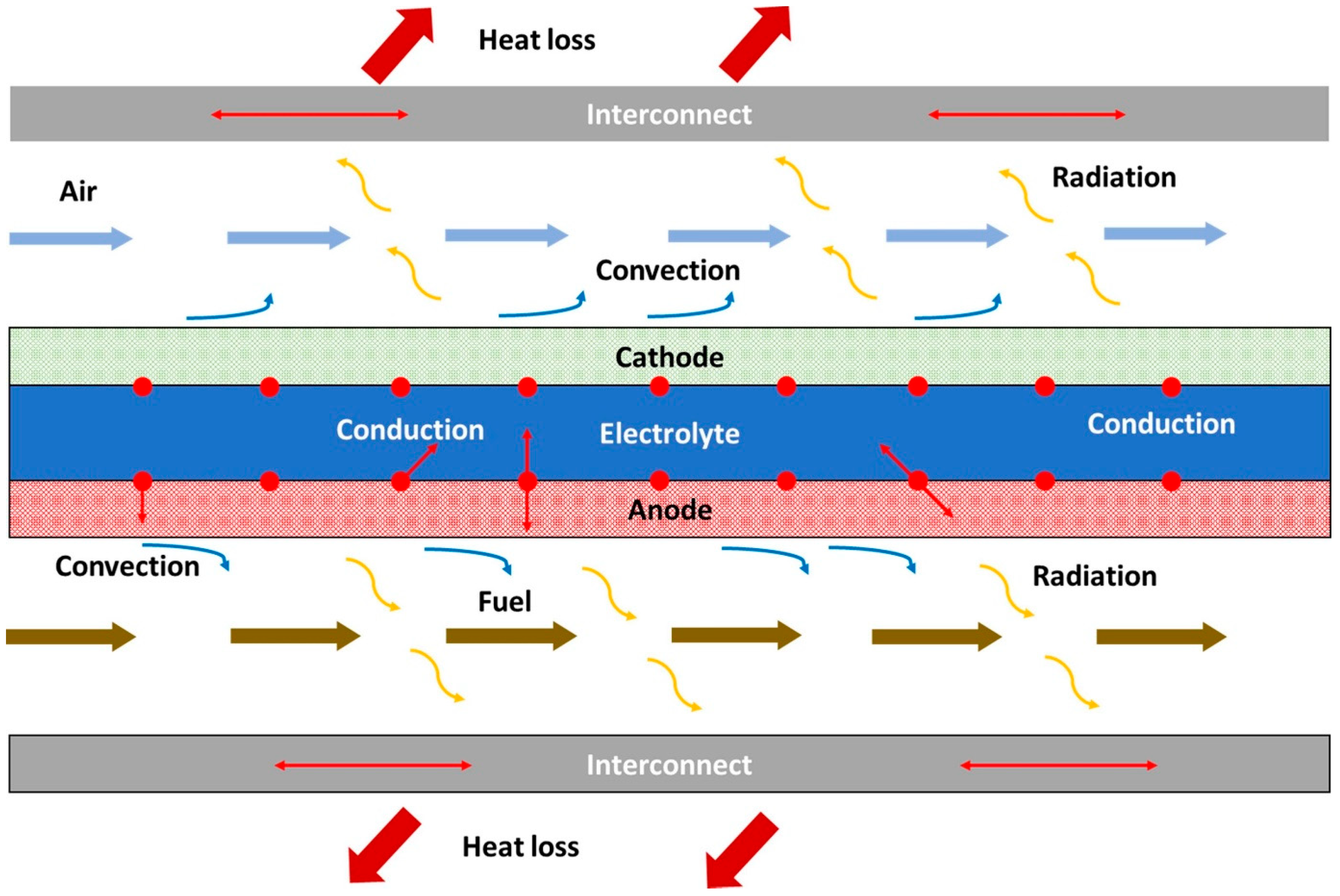
6.2. Large Thermal Gradients in Stack Systems

SOFC stacks are intriguing devices which work at a 10 kW stack for 1400 h, varying considerably from room temperature to 1000 °C. This energy conversion directly assumes that in each compartment, the gas phase mixture is at chemical equilibrium to study the cracking of the glass–ceramic or sealing interfaces, inducing a less stringent joining and reaching a maximum efficiency of 70% without insulation. The effect of the varying parameters in the SOFCs has been investigated using the response surface method, focused on the combined effects of material incompatibilities, particle growth, and contamination with the integrity of the stack components at the electrochemical reaction occurring from 600 C to 1000 C. Figure 23 shows the heat transfer in the non-uniform multi-stack design resulting from the electrochemical performance, causing localized reoxidation or reduction of the anode and cathode. The exothermic electrochemical reactions occurring under different boundary conditions used a metal-supported planar SOFC stack for a fast start-up process, resulting in a high volumetric stack power density, behaving as many individual heat sources in the electrochemically active part of the SOFC, giving rise to significant thermal stresses due to a mismatch of the coefficient of thermal expansion (CTE), fuel flexibility, and lower emissions due to high-temperature operation.
In a review article, challenges in using a perovskite-based anode for SOFCs for a range of fuels are studied [113]. Conventional nickel-based anodes for operation under various fuel environments provide sites for the oxidation of fuel to produce electricity. It was reported that the selection of anode materials, including the application of bimetallic and perovskite-based anodes, facilitated the activation of C–H bonds for hydrocarbon fuel oxidation. The development of anode materials led to high electrochemical performance and catalytic activity. Conventional nickel-based anodes rapidly break down the C–C bond, which increases the formation of carbon deposits on the active sites. Perovskite-based anodes showing a high concentration of oxygen vacancies can indirectly improve the electrochemical performance and favor the activation of C–H bonds. On the other hand, iron-based perovskite experiences phase instability in a reducing atmosphere, limiting its potential as an anode material for SOFC applications. The performance of single perovskite-based anodes operated in hydrocarbon can enhance cell performance and result in excellent carbon resistance. It was concluded that it is a promising anode for operation in hydrocarbon fuel, showing a high anode catalytic activity and paving the way for the development of cost-effective SOFCs.
Hadi et al. reviewed the preparation of anode materials to understand their effect on the performance of the deposited layers [114]. It was reported that one of the disadvantages of the sol–gel method for synthesizing anode materials for SOFC applications is its expensive process for large scale production. It was reported that screen-printing is a simple technique to prepare an SOFC anode, and the thickness of the film can be varied between 10 and 100 μm. The impregnation or infiltration method can lead to escalation in catalytic activity owing to the finely dispersed particles encouraged by the hydrogen dissociation.
Figure 23. Schematic of transport phenomena in a planar SOFC. Reproduced with permission [115].
Physchem 05 00025 g023

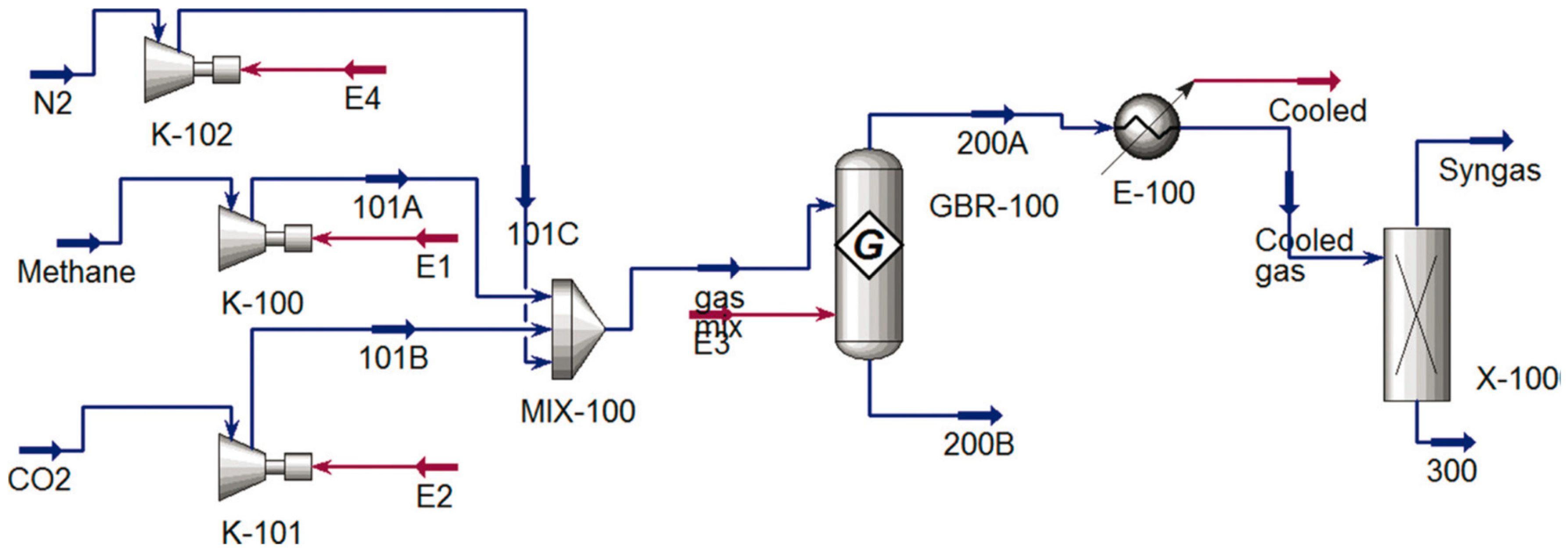
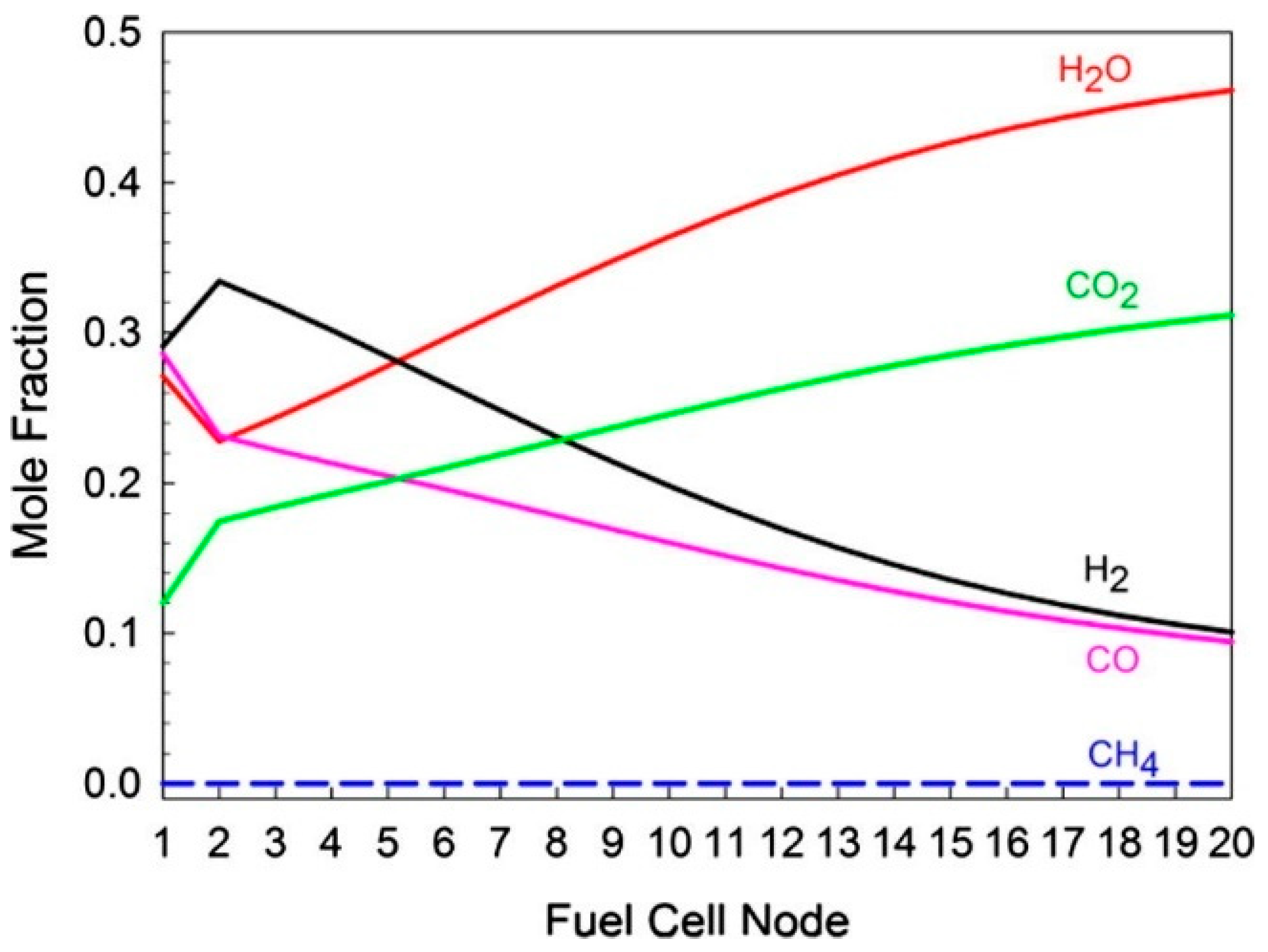
7. Analytical and Numerical Thermodynamic Equilibrium Simulations of Steam Methane Reforming (Computational Study)

Computer simulation is an important element in the design of chemical processes. A thermodynamic equilibrium steady-state analysis of SMR used as the process fuel is valid at micro, meso, and macro/plant scales lower than 10 °C/cm. Dmitry et al. employed a computational fluid dynamics (CFD) model of the steam methane reforming reaction to the highest attainable hydrogen concentration in the reformate steam for the real computational domain of the reformer [116]. It was reported that because of the principle behind SMR, each 100 mm catalyst bed incorporates the reaction section, leading to higher recovery values. The maximum temperature gradient is cooled through a strongly endothermic steam methane reforming reaction, due to the variation in the effectiveness of the factors throughout the reactor and the very small catalyst particles.
Varandas et al. studied numerical thermodynamic equilibrium considering the effect of temperature, pressure, and S/C ratio [117]. It was reported that SMR is a complex process susceptible to carbon deposition, making it difficult to perform dynamic simulations. Generally, nickel-based reforming catalysts were used to simulate methane to evaluate the optimal operational conditions. The observed trend indicates that the formation of coke is due to solid particles, representing the conditions for which the maximum values of CO are observed at 600 °C, when the temperature and pressure are the lowest. Additionally, hydrogen production leads to lower heat balance as the S/C ratio goes up. It was concluded that the maximum heat simulated would change the S/C ratio from 2.5 to 4, depending on the intake fuel and the constraints of solving the material balance equation system. The thermodynamic analysis showed a direct correlation between hydrogen production and rising temperatures, emphasizing the impact of enthalpy differences with potential challenges related to carbonaceous products.
In another study, a thermodynamic equilibrium analysis of SMR was performed for a wide range of operational conditions to calculate the amount of heat supplied to the reformer per 1 mol [118]. It was reported that to determine the degree of methane conversion, the dichotomy method was used in the SMR reaction system at different pressures. The dichotomy method is a root-finding technique used specifically in the temperature range before 1200 K, displaying the equilibrium composition of gas mixtures to determine the equilibrium gas composition at the outlet of the SMR reactor. Carbon formation is another aspect of the large-scale hydrogen production by SMR, allowing for the measurement of the required heat flux. It was concluded that a thermodynamic analysis of the SMR establishes an explicit dependence between the methane conversion and the amount of heat supplied to the reacting mixture.
A thermodynamic equilibrium analysis of the CO2 reforming of methane was carried out at total pressures of 1 and 20 bar to simulate this commercial process [119]. The addition of steam to the feed showed a positive effect on the methane activity and the syngas ratio. The thermodynamic equilibrium results using the Gibbs free minimization method for syngas production maximized the H2 and CO product yields. The thermodynamic analysis involved the chemical potential of all components, modeling steady-state and unsteady-state process systems. The Peng–Robinson equation of state was used in the fugacity calculations, favoring elevated temperatures and preventing the formation of solid carbon. The addition of extra steam to the feed stream caused a considerable decrease in carbon dioxide conversion and a decrease in hydrogen yield. The influence of pressure on methane DR was studied by increasing the pressure within the temperature range of 400–1200 °C. The equilibrium conversions of methane, carbon dioxide, and steam decreased in both the DR and combined DR–SR processes.
In another study, CFD-modeling via Ansys Fluent software was used to increase the efficiency of the SMR process in three reversible reactions, and the addition of noble metals to the nickel catalyst can enhance the reaction efficiency, leading to a considerable increase in the reactor throughput at the expense of a certain loss of the catalyst productivity [120]. It was reported that for the separation of hydrogen from a gas mixture, the maximum operating temperature was 973 K. It was concluded that the temperature of the reaction mixture reacts with steam over a catalyst to produce more hydrogen and carbon dioxide.
A 3D CFD model is developed to predict the SMR performance for various reactor scales with a hydrogen rate of 2.5 Nm3/h (6 kg/d) [121]. It was reported that the methane and hydrogen concentrations strongly depend on the kinetic study of the computed solutions to reach steady-state on various reactor configurations. It was concluded that the compact SMR reactor, with the effects of pressure and steam–methane ratio developed using the Langmuir–Hinshelwood–Hougen–Watson (LH-HW) approach, prevents catalyst bed deactivation. The CFD results showed an optimum feed distribution for various reactor scales. The flow rates of methane were set at 16 L/min, in which methane was passed through a condenser to remove water. The CFD simulation consists of the combustor and reactor, considering the gas phase as an incompressible ideal gas. A steady-state 3D simulation considering a species transport model, along with SMR reactions, were solved simultaneously. The fluid domain, considering a semi-empirical Ergun equation, satisfies the mathematical constraints on the Reynolds stresses and is obtained from the magnitude of each tensor. The heat transfer due to turbulent kinetic energy considers the diffusional limitation in large catalyst particles.
Lao et al. used CFD modeling to improve closed-loop dynamics and evaluate three different feedback controls that interact through heat exchange [122]. The steam methane reformer includes top burners, with the dramatic increase in computing power using a CFD model with a bench-scale that prevents the reactants from entering. Owing to the high Reynolds number, the catalyst particles inside the reforming tube track the set-point and compensate for the effect of the tube-side feed disturbance. It was reported that to accomplish the modeling objective, the CFD simulation of the single reforming tube was suitable for most SMR calculations. It was concluded that generating hydrogen fuel from steam and methane allows the reactants to diffuse into the catalyst pores, a conclusion derived based on a widely-accepted intrinsic SMR reaction kinetic model.

8. Conclusions and Future Work

Efficient usage of CH4, which is the most important environmentally friendly process, allows for the production of two types of biofuels. Direct application of CH4, however, will lead the fuel cells to act as power generators, resulting in quick deactivation, along with the degradation of long-term cell stability at elevated temperatures. In light of many recent developments, fuel reforming processes, such as SMR and DMR, can be used to identify the most economically viable production method for obtaining a mixture of hydrogen and carbon monoxide. Reforming CH4 into syngas, which can prevent hotspot in the catalyst bed during the operation of SOFCs, can be employed as an electrochemical reformer. Using a catalyst layer on the anode is a common internal reforming design, which can be used to operate SOFCs, enabling the pre-reforming of methane before gas penetration in the anode side. This technique can simplify the system and produce electrical power and heat at a high level of efficiency, with minimum carbon dioxide production.
Additionally, catalyst material selection is more flexible and reduces the risk of carbon formation in the stack on the cell anode by cracking the larger hydrocarbons. The reforming catalysts are materials that commonly include active sites, support, and nickel particles in the three-phase region (TPR) near the dense electrolyte membrane. The effects of the catalytic activity, sintering resistance, and coking resistance of CH4 reforming on the less active sites and those that are highly resistant toward carbon formation, accompanied by the simultaneous occurrence of the reverse water–gas shift reaction, the textural properties of the support, as well as the endothermal DMR process, can also benefit from the heat loss of SOFCs owing to the different polarizations associated with the hydrogen or carbon dioxide electrochemical oxidation. Regardless of the type of reforming catalyst, the very active type is associated with the number of active sites on the catalyst surface. Methane is activated on the active sites, while the ceramic oxygen-ion conductor YSZ itself also exhibits catalytic activity. The catalytic activity of the catalyst for CH4 reforming can only convert CO to hydrogen when sufficient H2O is present, depending on the elementary surface kinetics, the textural properties of the support, the average size of the active site, and the flexibility of using different hydrocarbon fuels, as well as its versatility in the electrolyte material.
It is suggested that the transfer to industrial button cells helps to prevent issues related to poor current and improved operating voltage, which implies the existence of microstructural inadequacies.
There are many relevant studies on the application of catalysts for the industrial synthesis of methanol or biogas, which naturally contain a large amount of methane. Improved electrochemical performance and stability are depicted after exposure to a higher temperature, resulting in the value of the bio-material as a clean resource. Nevertheless, some challenges limit the wide application of the catalyst layer design. The catalyst layer displays a certain limitation in that it lifts nickel crystallite from the support, and the reforming of shale gas into syngas impacts the technical, economic, environmental, and safety attributes of the process. Therefore, how to control its porosity and microstructure when considering the reactor design, hydrodynamics, and mass and heat transfer will influence the redox characteristics of the support material. Additionally, the fuel flow rate requires must be inhibited to significantly suppress the carbon formation and double the activity when using a catalyst layer. As a result, it is important to design a uniform temperature gradient along the cell to reduce chance of cell cracking in the stack. The development of direct CH4 SOFCs plays an important role in providing higher activity and stability. Hence, it is important to design catalyst layer materials with promising reforming catalytic activity, as well as carbon whisker formation. The commonly used nickel-based anodes, such as Ni–YSZ, serve as structural supports, affecting the concentrations of hydrogen, carbon monoxide, and hydrocarbon available to provide physical protection to the nickel nanoparticles. While this can be avoided, the lowest activity for the severe sintering of nickel particles requires the delineation of appropriate procedures and conditions for the stable and high-conversion operation of a nominal SOFC stack, resulting in the high coke resistance of the honeycomb nickel catalyst.

Funding

This research received no external funding.

Data Availability Statement

The data that support the findings of this study are available from the corresponding author upon reasonable request.

Conflicts of Interest

The author declares no conflict of interest.

References

  1. Stambouli, A.B.; Traversa, E. Solid Oxide Fuel Cells (SOFCs): A Review of an Environmentally Clean and Efficient Source of Energy. Renew. Sustain. Energy Rev. 2002, 6, 433–455. [Google Scholar] [CrossRef]
  2. Alaedini, A.H.; Tourani, H.K.; Saidi, M. A Review of Waste-to-Hydrogen Conversion Technologies for Solid Oxide Fuel Cell (SOFC) Applications: Aspect of Gasification Process and Catalyst Development. J. Environ. Manag. 2023, 329, 117077. [Google Scholar] [CrossRef] [PubMed]
  3. Shabri, H.A.; Othman, M.H.D.; Mohamed, M.A.; Kurniawan, T.A.; Jamil, S.M. Recent Progress in Metal-Ceramic Anode of Solid Oxide Fuel Cell for Direct Hydrocarbon Fuel Utilization: A Review. Fuel Process. Technol. 2021, 212, 106626. [Google Scholar] [CrossRef]
  4. Shah, M.A.K.Y.; Lu, Y.; Mushtaq, N.; Yousaf, M.; Akbar, N.; Xia, C.; Yun, S.; Zhu, B. Semiconductor-Membrane Fuel Cell (SMFC) for Renewable Energy Technology. Renew. Sustain. Energy Rev. 2023, 185, 113639. [Google Scholar] [CrossRef]
  5. Dwivedi, S. Solid Oxide Fuel Cell: Materials for Anode, Cathode and Electrolyte. Int. J. Hydrogen Energy 2020, 45, 23988–24013. [Google Scholar] [CrossRef]
  6. Liu, K.; Song, C.; Subramani, V. Hydrogen and Syngas Production and Purification Technologies; John Wiley & Sons: New York, NY, USA, 2010; ISBN 0471719757. [Google Scholar]
  7. Hanak, D.P.; Jenkins, B.G.; Kruger, T.; Manovic, V. High-Efficiency Negative-Carbon Emission Power Generation from Integrated Solid-Oxide Fuel Cell and Calciner. Appl. Energy 2017, 205, 1189–1201. [Google Scholar] [CrossRef]
  8. Lestari, N.A. Reduction of Co_2 Emission by Integrated Biomass Gasification-Solid Oxide Fuel Cell Combined with Heat Recovery and in-Situ Co_2 Utilization. Evergreen 2019, 6, 254–261. [Google Scholar] [CrossRef]
  9. Ramos, A.; Rouboa, A. Syngas Production Strategies from Biomass Gasification: Numerical Studies for Operational Conditions and Quality Indexes. Renew. Energy 2020, 155, 1211–1221. [Google Scholar] [CrossRef]
  10. Göransson, K.; Söderlind, U.; He, J.; Zhang, W. Review of Syngas Production via Biomass DFBGs. Renew. Sustain. Energy Rev. 2011, 15, 482–492. [Google Scholar] [CrossRef]
  11. Wan, W. An Innovative System by Integrating the Gasification Unit with the Supercritical Water Unit to Produce Clean Syngas for Solid Oxide Fuel Cell (SOFC): System Performance Assessment. Int. J. Hydrogen Energy 2016, 41, 22698–22710. [Google Scholar] [CrossRef]
  12. Rosen, M.A. Thermodynamic Investigation of Hydrogen Production by Steam-Methane Reforming. Int. J. Hydrogen Energy 1991, 16, 207–217. [Google Scholar] [CrossRef]
  13. Bhat, S.A.; Sadhukhan, J. Process Intensification Aspects for Steam Methane Reforming: An Overview. AIChE J. 2009, 55, 408–422. [Google Scholar] [CrossRef]
  14. Carapellucci, R.; Giordano, L. Steam, Dry and Autothermal Methane Reforming for Hydrogen Production: A Thermodynamic Equilibrium Analysis. J. Power Sources 2020, 469, 228391. [Google Scholar] [CrossRef]
  15. Fuqiang, W.; Lin, J.; Ziming, C.; Huaxu, L.; Jianyu, T. Combination of Thermodynamic Analysis and Regression Analysis for Steam and Dry Methane Reforming. Int. J. Hydrogen Energy 2019, 44, 15795–15810. [Google Scholar] [CrossRef]
  16. Jafarbegloo, M.; Tarlani, A.; Mesbah, A.W.; Sahebdelfar, S. Thermodynamic Analysis of Carbon Dioxide Reforming of Methane and Its Practical Relevance. Int. J. Hydrogen Energy 2015, 40, 2445–2451. [Google Scholar] [CrossRef]
  17. Ayodele, B.V.; Cheng, C.K. Process Modelling, Thermodynamic Analysis and Optimization of Dry Reforming, Partial Oxidation and Auto-Thermal Methane Reforming for Hydrogen and Syngas Production. Chem. Prod. Process Model. 2015, 10, 211–220. [Google Scholar] [CrossRef]
  18. Nieva, M.A.; Villaverde, M.M.; Monzón, A.; Garetto, T.F.; Marchi, A.J. Steam-Methane Reforming at Low Temperature on Nickel-Based Catalysts. Chem. Eng. J. 2014, 235, 158–166. [Google Scholar] [CrossRef]
  19. Salahi, F.; Zarei-Jelyani, F.; Meshksar, M.; Farsi, M.; Rahimpour, M.R. Application of Hollow Promoted Ni-Based Catalysts in Steam Methane Reforming. Fuel 2023, 334, 126601. [Google Scholar] [CrossRef]
  20. Bian, Z.; Das, S.; Wai, M.H.; Hongmanorom, P.; Kawi, S. A Review on Bimetallic Nickel-based Catalysts for CO2 Reforming of Methane. ChemPhysChem 2017, 18, 3117–3134. [Google Scholar] [CrossRef]
  21. Lo Faro, M.; Modafferi, V.; Frontera, P.; Antonucci, P.; Aricò, A.S. Catalytic Behavior of Ni-Modified Perovskite and Doped Ceria Composite Catalyst for the Conversion of Odorized Propane to Syngas. Fuel Process. Technol. 2013, 113, 28–33. [Google Scholar] [CrossRef]
  22. Bian, Z.; Wang, Z.; Jiang, B.; Hongmanorom, P.; Zhong, W.; Kawi, S. A Review on Perovskite Catalysts for Reforming of Methane to Hydrogen Production. Renew. Sustain. Energy Rev. 2020, 134, 110291. [Google Scholar] [CrossRef]
  23. Ding, H.; Xu, Y.; Luo, C.; Wang, Q.; Shen, C.; Xu, J.; Zhang, L. A Novel Composite Perovskite-Based Material for Chemi-cal-Looping Steam Methane Reforming to Hydrogen and Syngas. Energy Convers. Manag. 2018, 171, 12–19. [Google Scholar] [CrossRef]
  24. Bobrova, L.N.; Sadykov, V.A.; Mezentseva, N.V.; Pelipenko, V.V.; Vernikovskaya, N.V.; Klenov, O.P.; Smorygo, O.L. Catalytic Performance of Structured Packages Coated with Perovskite-Based Nanocomposite in the Methane Steam Reforming Reaction. Int. J. Hydrogen Energy 2016, 41, 4632–4645. [Google Scholar] [CrossRef]
  25. Araújo, P.M.; da Costa, K.M.; Passos, F.B. Hydrogen Production from Methane Autothermal Reforming over CaTiO3, BaTiO3 and SrTiO3 Supported Nickel Catalysts. Int. J. Hydrogen Energy 2021, 46, 24107–24116. [Google Scholar] [CrossRef]
  26. Chen, L.; Pradhan, S. Low Temperature Synthesis of Metal Doped Perovskites Catalyst for Hydrogen Production by Autothermal Reforming of Methane. Int. J. Hydrogen Energy 2016, 41, 14605–14614. [Google Scholar] [CrossRef]
  27. Su, Y.-J.; Pan, K.-L.; Chang, M.-B. Modifying Perovskite-Type Oxide Catalyst LaNiO3 with Ce for Carbon Dioxide Reforming of Methane. Int. J. Hydrogen Energy 2014, 39, 4917–4925. [Google Scholar] [CrossRef]
  28. Niakolas, D.K. Sulfur Poisoning of Ni-Based Anodes for Solid Oxide Fuel Cells in H/C-Based Fuels. Appl. Catal. A Gen. 2014, 486, 123–142. [Google Scholar] [CrossRef]
  29. Chen, Y.; Zhang, Y.; Lin, Y.; Yang, Z.; Su, D.; Han, M.; Chen, F. Direct-Methane Solid Oxide Fuel Cells with Hierarchically Porous Ni-Based Anode Deposited with Nanocatalyst Layer. Nano Energy 2014, 10, 1–9. [Google Scholar] [CrossRef]
  30. Ormerod, R.M. Solid Oxide Fuel Cells. Chem. Soc. Rev. 2003, 32, 17–28. [Google Scholar] [CrossRef]
  31. Zhang, W.; Hu, X.; Zhou, Y.; Luo, Z.; Nam, G.; Ding, Y.; Li, T.; Liu, Z.; Ahn, Y.; Kane, N. A Solid Oxide Fuel Cell Runs on Hydrocarbon Fuels with Exceptional Durability and Power Output. Adv. Energy Mater. 2022, 12, 2202928. [Google Scholar] [CrossRef]
  32. Yu, N.; Liu, T.; Chen, X.; Miao, M.; Ni, M.; Wang, Y. Co-Generation of Liquid Chemicals and Electricity over Co-Fe Alloy/Perovskite Anode Catalyst in a Propane Fueled Solid Oxide Fuel Cell. Sep. Purif. Technol. 2022, 291, 120890. [Google Scholar] [CrossRef]
  33. Wang, W.; Ran, R.; Shao, Z. Combustion-Synthesized Ru–Al2O3 Composites as Anode Catalyst Layer of a Solid Oxide Fuel Cell Operating on Methane. Int. J. Hydrogen Energy 2011, 36, 755–764. [Google Scholar] [CrossRef]
  34. Wang, Z.; Wang, Z.; Yang, W.; Peng, R.; Lu, Y. Carbon-Tolerant Solid Oxide Fuel Cells Using NiTiO3 as an Anode Internal Reforming Layer. J. Power Sources 2014, 255, 404–409. [Google Scholar] [CrossRef]
  35. Wang, L.; Fan, Y.; Li, J.; Shao, L.; Xi, X.; Fu, X.-Z.; Luo, J.-L. La0.5Sr0.5Fe0.9Mo0.1O3−δ-CeO2 Anode Catalyst for Co-Producing Electricity and Ethylene from Ethane in Proton-Conducting Solid Oxide Fuel Cells. Ceram. Int. 2021, 47, 24106–24114. [Google Scholar] [CrossRef]
  36. Cui, S.-H.; Li, J.-H.; Luo, J.-L.; Chuang, K.T.; Qiao, L.-J. Co-Generation of Energy and Ethylene in Hydrocarbon Fueled SOFCs with Cr3C2 and WC Anode Catalysts. Ceram. Int. 2014, 40, 11781–11786. [Google Scholar] [CrossRef]
  37. Zhao, K.; Lee, K.-S.; Chen, M.; Kim, B.-H.; Xu, Q.; Ahn, B.-G. Electrochemical Performance of a Copper-Impregnated Ni–Ce0.8Sm0.2O1.9 Anode Running on Methane. Int. J. Hydrogen Energy 2013, 38, 3750–3756. [Google Scholar] [CrossRef]
  38. Xie, Y.; Shi, N.; Hu, X.; Liu, M.; Yang, Y.; Huan, D.; Pan, Y.; Peng, R.; Xia, C. Novel In-Situ MgO Nano-Layer Decorated Carbon-Tolerant Anode for Solid Oxide Fuel Cells. Int. J. Hydrogen Energy 2020, 45, 11791–11801. [Google Scholar] [CrossRef]
  39. Thieu, C.; Park, S.; Kim, H.; Ji, H.; Lee, J.; Yoon, K.J.; Yang, S.; Son, J. Improved Electrochemical Performance and Durability of Butane-operating Low-temperature Solid Oxide Fuel Cell through Palladium Infiltration. Int. J. Energy Res. 2020, 44, 9995–10007. [Google Scholar] [CrossRef]
  40. Yang, L.; Choi, Y.; Qin, W.; Chen, H.; Blinn, K.; Liu, M.; Liu, P.; Bai, J.; Tyson, T.A.; Liu, M. Promotion of Water-Mediated Carbon Removal by Nanostructured Barium Oxide/Nickel Interfaces in Solid Oxide Fuel Cells. Nat. Commun. 2011, 2, 357. [Google Scholar] [CrossRef]
  41. Liu, S.; Chuang, K.T.; Luo, J.-L. Double-Layered Perovskite Anode with in Situ Exsolution of a Co–Fe Alloy to Cogenerate Ethylene and Electricity in a Proton-Conducting Ethane Fuel Cell. Acs Catal. 2016, 6, 760–768. [Google Scholar] [CrossRef]
  42. Li, J.; Hou, J.; Xi, X.; Lu, Y.; Li, M.; Fan, Y.; Wang, L.; Wang, L.; Fu, X.-Z.; Luo, J.-L. Cogeneration of Ethylene and Electricity in Symmetrical Protonic Solid Oxide Fuel Cells Based on a La0.6Sr0.4Fe0.8Nb0.1Cu0.1O3−δ Electrode. J. Mater. Chem. A 2020, 8, 25978–25985. [Google Scholar] [CrossRef]
  43. Ye, X.-F.; Huang, B.; Wang, S.R.; Wang, Z.R.; Xiong, L.; Wen, T.L. Preparation and Performance of a Cu–CeO2–ScSZ Composite Anode for SOFCs Running on Ethanol Fuel. J. Power Sources 2007, 164, 203–209. [Google Scholar] [CrossRef]
  44. Wang, W.; Chen, Y.; Wang, F.; Tade, M.O.; Shao, Z. Enhanced Electrochemical Performance, Water Storage Capability and Coking Resistance of a Ni+BaZr0.1Ce0.7Y0.1Yb0.1O3−δ Anode for Solid Oxide Fuel Cells Operating on Ethanol. Chem. Eng. Sci. 2015, 126, 22–31. [Google Scholar] [CrossRef]
  45. Wang, Y.; Yang, J.; Wang, J.; Guan, W.; Chi, B.; Jia, L.; Chen, J.; Muroyama, H.; Matsui, T.; Eguchi, K. Low–Temperature Ammonia Decomposition Catalysts for Direct Ammonia Solid Oxide Fuel Cells. J. Electrochem. Soc. 2020, 167, 64501. [Google Scholar] [CrossRef]
  46. Hashinokuchi, M.; Zhang, M.; Doi, T.; Inaba, M. Enhancement of Anode Activity and Stability by Cr Addition at Ni/Sm-Doped CeO2 Cermet Anodes in NH3-Fueled Solid Oxide Fuel Cells. Solid State Ion. 2018, 319, 180–185. [Google Scholar] [CrossRef]
  47. Sunarso, J.; Hashim, S.S.; Zhu, N.; Zhou, W. Perovskite Oxides Applications in High Temperature Oxygen Separation, Solid Oxide Fuel Cell and Membrane Reactor: A Review. Prog. Energy Combust. Sci. 2017, 61, 57–77. [Google Scholar] [CrossRef]
  48. Kaur, P.; Singh, K. Review of Perovskite-Structure Related Cathode Materials for Solid Oxide Fuel Cells. Ceram. Int. 2020, 46, 5521–5535. [Google Scholar] [CrossRef]
  49. Burnwal, S.K.; Bharadwaj, S.; Kistaiah, P. Review on MIEC Cathode Materials for Solid Oxide Fuel Cells. J. Mol. Eng. Mater. 2016, 4, 1630001. [Google Scholar] [CrossRef]
  50. Navarrete, L.; Balaguer, M.; Vert, V.B.; Serra, J.M. Tailoring Electrocatalytic Properties of Solid Oxide Fuel Cell Composite Cathodes Based on (La0.8Sr0.2)0.95MnO3+δ and Doped Cerias Ce1−XLnxO2−δ (Ln = Gd, La, Er, Pr, Tb and x = 0.1–0.2). Fuel Cells 2017, 17, 100–107. [Google Scholar] [CrossRef]
  51. Goodenough, J.B.; Huang, Y.-H. Alternative Anode Materials for Solid Oxide Fuel Cells. J. Power Sources 2007, 173, 1–10. [Google Scholar] [CrossRef]
  52. Shu, L.; Sunarso, J.; Hashim, S.S.; Mao, J.; Zhou, W.; Liang, F. Advanced Perovskite Anodes for Solid Oxide Fuel Cells: A Review. Int. J. Hydrogen Energy 2019, 44, 31275–31304. [Google Scholar] [CrossRef]
  53. Cheng, Z.; Wang, J.-H.; Choi, Y.; Yang, L.; Lin, M.-C.; Liu, M. From Ni-YSZ to Sulfur-Tolerant Anode Materials for SOFCs: Electrochemical Behavior, in Situ Characterization, Modeling, and Future Perspectives. Energy Environ. Sci. 2011, 4, 4380–4409. [Google Scholar] [CrossRef]
  54. Kim, T.W.; Park, J.C.; Lim, T.-H.; Jung, H.; Chun, D.H.; Lee, H.T.; Hong, S.; Yang, J.-I. The Kinetics of Steam Methane Reforming over a Ni/γ-Al2O3 Catalyst for the Development of Small Stationary Reformers. Int. J. Hydrogen Energy 2015, 40, 4512–4518. [Google Scholar] [CrossRef]
  55. Zeppieri, M.; Villa, P.L.; Verdone, N.; Scarsella, M.; De Filippis, P. Kinetic of Methane Steam Reforming Reaction over Nickel- and Rhodium-Based Catalysts. Appl. Catal. A Gen. 2010, 387, 147–154. [Google Scholar] [CrossRef]
  56. Chen, L.; Qi, Z.; Zhang, S.; Su, J.; Somorjai, G.A. Catalytic Hydrogen Production from Methane: A Review on Recent Progress and Prospect. Catalysts 2020, 10, 858. [Google Scholar] [CrossRef]
  57. Garbarino, G.; Pugliese, F.; Cavattoni, T.; Busca, G.; Costamagna, P. A Study on CO2 Methanation and Steam Methane Reforming over Commercial Ni/Calcium Aluminate Catalysts. Energies 2020, 13, 2792. [Google Scholar] [CrossRef]
  58. Matsumura, Y.; Nakamori, T. Steam Reforming of Methane over Nickel Catalysts at Low Reaction Temperature. Appl. Catal. A Gen. 2004, 258, 107–114. [Google Scholar] [CrossRef]
  59. Rakass, S.; Oudghiri-Hassani, H.; Rowntree, P.; Abatzoglou, N. Steam Reforming of Methane over Unsupported Nickel Catalysts. J. Power Sources 2006, 158, 485–496. [Google Scholar] [CrossRef]
  60. Hasanat, A.U.; Khoja, A.H.; Naeem, N.; Al-Anazi, A.; Liaquat, R.; Khan, B.A.; Din, I.U. Thermocatalytic Partial Oxidation of Methane to Syngas (H2, CO) Production Using Ni/La2O3 Modified Biomass Fly Ash Supported Catalyst. Results Eng. 2023, 19, 101333. [Google Scholar] [CrossRef]
  61. Calise, F.; Cappiello, F.L.; Vicidomini, M. Chapter 9-Applications of Solar PV Systems in Hydrogen Production. In Photovoltaic Solar Energy Conversion; Academic Press: Cambridge, MA, USA, 2020; pp. 275–312. ISBN 978-0-12-819610-6. [Google Scholar]
  62. Araújo, J.C.S.; Oton, L.F.; Oliveira, A.C.; Lang, R.; Otubo, L.; Bueno, J.M.C. On the Role of Size Controlled Pt Particles in Nanostructured Pt-Containing Al2O3 Catalysts for Partial Oxidation of Methane. Int. J. Hydrogen Energy 2019, 44, 27329–27342. [Google Scholar] [CrossRef]
  63. Costa, D.S.; Gomes, R.S.; Rodella, C.B.; da Silva, R.B.; Fréty, R.; Teixeira Neto, É.; Brandão, S.T. Study of Nickel, Lanthanum and Niobium-Based Catalysts Applied in the Partial Oxidation of Methane. Catal. Today 2020, 344, 15–23. [Google Scholar] [CrossRef]
  64. Özdemir, H.; Öksüzömer, M.F. Synthesis of Al2O3, MgO and MgAl2O4 by Solution Combustion Method and Investigation of Performances in Partial Oxidation of Methane. Powder Technol. 2020, 359, 107–117. [Google Scholar] [CrossRef]
  65. Moral, A.; Reyero, I.; Llorca, J.; Bimbela, F.; Gandía, L.M. Partial Oxidation of Methane to Syngas Using Co/Mg and Co/Mg-Al Oxide Supported Catalysts. Catal. Today 2019, 333, 259–267. [Google Scholar] [CrossRef]
  66. Figen, H.E.; Baykara, S.Z. Hydrogen Production by Partial Oxidation of Methane over Co Based, Ni and Ru Monolithic Catalysts. Int. J. Hydrogen Energy 2015, 40, 7439–7451. [Google Scholar] [CrossRef]
  67. Faria, E.C.; Neto, R.C.R.; Colman, R.C.; Noronha, F.B. Hydrogen Production through CO2 Reforming of Methane over Ni/CeZrO2/Al2O3 Catalysts. Catal. Today 2014, 228, 138–144. [Google Scholar] [CrossRef]
  68. Kurdi, A.N.; Ibrahim, A.A.; Al-Fatesh, A.S.; Alquraini, A.A.; Abasaeed, A.E.; Fakeeha, A.H. Hydrogen Production from CO2 Reforming of Methane Using Zirconia Supported Nickel Catalyst. RSC Adv. 2022, 12, 10846–10854. [Google Scholar] [CrossRef]
  69. Rahmani, F.; Haghighi, M.; Vafaeian, Y.; Estifaee, P. Hydrogen Production via CO2 Reforming of Methane over ZrO2-Doped Ni/ZSM-5 Nanostructured Catalyst Prepared by Ultrasound Assisted Sequential Impregnation Method. J. Power Sources 2014, 272, 816–827. [Google Scholar] [CrossRef]
  70. Sajjadi, S.M.; Haghighi, M.; Eslami, A.A.; Rahmani, F. Hydrogen Production via CO2-Reforming of Methane over Cu and Co Doped Ni/Al2O3 Nanocatalyst: Impregnation versus Sol–Gel Method and Effect of Process Conditions and Promoter. J. Sol-Gel Sci. Technol. 2013, 67, 601–617. [Google Scholar] [CrossRef]
  71. Kumar, N.; Shojaee, M.; Spivey, J.J. Catalytic Bi-Reforming of Methane: From Greenhouse Gases to Syngas. Curr. Opin. Chem. Eng. 2015, 9, 8–15. [Google Scholar] [CrossRef]
  72. He, D.; Zhang, Y.; Wang, Z.; Mei, Y.; Jiang, Y. Bi-Reforming of Methane with Carbon Dioxide and Steam on Nickel-Supported Binary Mg–Al Metal Oxide Catalysts. Energy Fuels 2020, 34, 4822–4827. [Google Scholar] [CrossRef]
  73. Singh, S.; Bahari, M.B.; Abdullah, B.; Phuong, P.T.T.; Truong, Q.D.; Vo, D.-V.N.; Adesina, A.A. Bi-Reforming of Methane on Ni/SBA-15 Catalyst for Syngas Production: Influence of Feed Composition. Int. J. Hydrogen Energy 2018, 43, 17230–17243. [Google Scholar] [CrossRef]
  74. Yang, X. An Experimental Investigation on the Deactivation and Regeneration of a Steam Reforming Catalyst. Renew. Energy 2017, 112, 17–24. [Google Scholar] [CrossRef]
  75. Eschemann, T.O.; de Jong, K.P. Deactivation Behavior of Co/TiO2 Catalysts during Fischer–Tropsch Synthesis. ACS Catal. 2015, 5, 3181–3188. [Google Scholar] [CrossRef]
  76. Pham Minh, D.; Pham, X.-H.; Siang, T.J.; Vo, D.V.N. Review on the Catalytic Tri-Reforming of Methane-Part I: Impact of Operating Conditions, Catalyst Deactivation and Regeneration. Appl. Catal. A Gen. 2021, 621, 118202. [Google Scholar] [CrossRef]
  77. Zhou, L.; Li, L.; Wei, N.; Li, J.; Basset, J. Effect of NiAl2O4 Formation on Ni/Al2O3 Stability during Dry Reforming of Methane. ChemCatChem 2015, 7, 2508–2516. [Google Scholar] [CrossRef]
  78. Theofanidis, S.-A.; Pieterse, J.A.Z.; Poelman, H.; Longo, A.; Sabbe, M.K.; Virginie, M.; Detavernier, C.; Marin, G.B.; Galvita, V. V Effect of Rh in Ni-Based Catalysts on Sulfur Impurities during Methane Reforming. Appl. Catal. B Environ. 2020, 267, 118691. [Google Scholar] [CrossRef]
  79. Gallego, J.; Batiot-Dupeyrat, C.; Barrault, J.; Mondragón, F. Severe Deactivation of a LaNiO3 Perovskite-Type Catalyst Precursor with H2S during Methane Dry Reforming. Energy & Fuels 2009, 23, 4883–4886. [Google Scholar] [CrossRef]
  80. Aznam, I.; Muchtar, A.; Somalu, M.R.; Baharuddin, N.A.; Rosli, N.A.H. Advanced Materials for Heterogeneous Catalysis: A Comprehensive Review of Spinel Materials for Direct Internal Reforming of Methane in Solid Oxide Fuel Cell. Chem. Eng. J. 2023, 471, 144751. [Google Scholar] [CrossRef]
  81. Nakagawa, N.; Sagara, H.; Kato, K. Catalytic Activity of Ni–YSZ–CeO2 Anode for the Steam Reforming of Methane in a Direct Internal-Reforming Solid Oxide Fuel Cell. J. Power Sources 2001, 92, 88–94. [Google Scholar] [CrossRef]
  82. Saebea, D.; Authayanun, S.; Patcharavorachot, Y. Performance Analysis of Direct Steam Reforming of Methane in SOFC with SDC-Based Electrolyte. Energy Rep. 2020, 6, 391–396. [Google Scholar] [CrossRef]
  83. Kawano, M.; Matsui, T.; Kikuchi, R.; Yoshida, H.; Inagaki, T.; Eguchi, K. Direct Internal Steam Reforming at SOFC Anodes Composed of NiO–SDC Composite Particles. J. Electrochem. Soc. 2007, 154, B460. [Google Scholar] [CrossRef]
  84. Arpornwichanop, A.; Chalermpanchai, N.; Patcharavorachot, Y.; Assabumrungrat, S.; Tade, M. Performance of an Anode-Supported Solid Oxide Fuel Cell with Direct-Internal Reforming of Ethanol. Int. J. Hydrogen Energy 2009, 34, 7780–7788. [Google Scholar] [CrossRef]
  85. Wongchanapai, S.; Iwai, H.; Saito, M.; Yoshida, H. Selection of Suitable Operating Conditions for Planar Anode-Supported Direct-Internal-Reforming Solid-Oxide Fuel Cell. J. Power Sources 2012, 204, 14–24. [Google Scholar] [CrossRef]
  86. Fu, Q.; Li, Z.; Wei, W.; Liu, F.; Xu, X.; Liu, Z. Performance Degradation Prediction of Direct Internal Reforming Solid Oxide Fuel Cell Due to Ni-Particle Coarsening in Composite Anode. Energy Convers. Manag. 2021, 233, 113902. [Google Scholar] [CrossRef]
  87. Wei, T.; Liu, B.; Jia, L.; Li, R. Perovskite Materials for Highly Efficient Catalytic CH4 Fuel Reforming in Solid Oxide Fuel Cell. Int. J. Hydrogen Energy 2021, 46, 24441–24460. [Google Scholar] [CrossRef]
  88. Chang, H.; Chen, H.; Yang, G.; Shi, J.; Zhou, W.; Bai, J.; Wang, Y.; Li, S. Enhanced Coking Resistance of Ni Cermet Anodes for Solid Oxide Fuel Cells Based on Methane On-cell Reforming by a Redox-stable Double-perovskite Sr2MoFeO6−δ. Int. J. Energy Res. 2019, 43, 2527–2537. [Google Scholar] [CrossRef]
  89. Yin, Y.; Li, S.; Xia, C.; Meng, G. Electrochemical Performance of IT-SOFCs with a Double-Layer Anode. J. Power Sources 2007, 167, 90–93. [Google Scholar] [CrossRef]
  90. Zhan, Z.; Barnett, S.A. An Octane-Fueled Solid Oxide Fuel Cell. Science 2005, 308, 844–847. [Google Scholar] [CrossRef]
  91. Yan, J.; Guo, W.; Chen, H.; Shi, J.; Cheng, F.; Li, S.; Shao, Z. Improvement of Solid Oxide Fuel Cell Performance by a Core-shell Structured Catalyst Using Low Concentration Coal Bed Methane Fuel. Int. J. Energy Res. 2020, 44, 5516–5526. [Google Scholar] [CrossRef]
  92. Steil, M.C.; Nobrega, S.D.; Georges, S.; Gelin, P.; Uhlenbruck, S.; Fonseca, F.C. Durable Direct Ethanol Anode-Supported Solid Oxide Fuel Cell. Appl. Energy 2017, 199, 180–186. [Google Scholar] [CrossRef]
  93. Zhang, P.; Yang, Z.; Jin, Y.; Liu, C.; Lei, Z.; Chen, F.; Peng, S. Progress Report on the Catalyst Layers for Hydrocarbon-Fueled SOFCs. Int. J. Hydrogen Energy 2021, 46, 39369–39386. [Google Scholar] [CrossRef]
  94. Zhao, J.; Xu, X.; Li, M.; Zhou, W.; Liu, S.; Zhu, Z. Coking-Resistant Ce0.8Ni0.2O2−δ Internal Reforming Layer for Direct Methane Solid Oxide Fuel Cells. Electrochim. Acta 2018, 282, 402–408. [Google Scholar] [CrossRef]
  95. Yuan, X.; Chen, H.; Tian, W.; Shi, J.; Zhou, W.; Cheng, F.; Li, S.-D.; Shao, Z. Utilization of Low-Concentration Coal-Bed Gas to Generate Power Using a Core-Shell Catalyst-Modified Solid Oxide Fuel Cell. Renew. Energy 2020, 147, 602–609. [Google Scholar] [CrossRef]
  96. Wang, W.; Zhou, W.; Ran, R.; Cai, R.; Shao, Z. Methane-Fueled SOFC with Traditional Nickel-Based Anode by Applying Ni/Al2O3 as a Dual-Functional Layer. Electrochem. Commun. 2009, 11, 194–197. [Google Scholar] [CrossRef]
  97. Futamura, S.; Muramoto, A.; Tachikawa, Y.; Matsuda, J.; Lyth, S.M.; Shiratori, Y.; Taniguchi, S.; Sasaki, K. SOFC Anodes Impregnated with Noble Metal Catalyst Nanoparticles for High Fuel Utilization. Int. J. Hydrogen Energy 2019, 44, 8502–8518. [Google Scholar] [CrossRef]
  98. Wang, W.; Su, C.; Ran, R.; Shao, Z. A New Gd-Promoted Nickel Catalyst for Methane Conversion to Syngas and as an Anode Functional Layer in a Solid Oxide Fuel Cell. J. Power Sources 2011, 196, 3855–3862. [Google Scholar] [CrossRef]
  99. Dewa, M.; Elharati, M.A.; Hussain, A.M.; Miura, Y.; Song, D.; Fukuyama, Y.; Furuya, Y.; Dale, N.; Zhang, X.; Marin-Flores, O.G.; et al. Metal-Supported Solid Oxide Fuel Cell System with Infiltrated Reforming Catalyst Layer for Direct Ethanol Feed Operation. J. Power Sources 2022, 541, 231625. [Google Scholar] [CrossRef]
  100. Park, E.K.; Lee, S.; Yun, J.W. Characteristics of Sr0.92Y0.08Ti1-YNiyO3−δ Anode and Ni-Infiltrated Sr0.92Y0.08TiO3−δ Anode Using CH4 Fuel in Solid Oxide Fuel Cells. Appl. Surf. Sci. 2018, 429, 171–179. [Google Scholar] [CrossRef]
  101. Kong, X.; Tian, Y.; Zhou, X.; Wu, X.; Zhang, J. Surface Tuned La0.9Ca0.1Fe0.9Nb0.1O3−δ Based Anode for Direct Methane Solid Oxide Fuel Cells by Infiltration Method. Electrochim. Acta 2017, 234, 71–81. [Google Scholar] [CrossRef]
  102. Xiao, P.; Ge, X.; Zhang, L.; Lee, J.-M.; Wang, J.-Y.; Wang, X. H2 and CH4 Oxidation on Gd0.2Ce0.8O1.9 Infiltrated SrMoO3–Yttria-Stabilized Zirconia Anode for Solid Oxide Fuel Cells. Int. J. Hydrogen Energy 2012, 37, 18349–18356. [Google Scholar] [CrossRef]
  103. Mo, B.; Rix, J.; Pal, U.; Basu, S.; Gopalan, S. Improving SOFC Anode Electrocatalytic Activity Using Nanoparticle Infiltration into MIEC Compositions. J. Electrochem. Soc. 2020, 167, 134506. [Google Scholar] [CrossRef]
  104. Kim, G.; Lee, S.; Shin, J.Y.; Corre, G.; Irvine, J.T.S.; Vohs, J.M.; Gorte, R.J. Investigation of the Structural and Catalytic Requirements for High-Performance SOFC Anodes Formed by Infiltration of LSCM. Electrochem. Solid-State Lett. 2009, 12, B48. [Google Scholar] [CrossRef]
  105. Xu, J.; Zhou, X.; Dong, X.; Pan, L.; Sun, K. Catalytic Activity of Infiltrated La0.3Sr0.7Ti0.3Fe0.7O3−δ–CeO2 as a Composite SOFC Anode Material for H2 and CO Oxidation. Int. J. Hydrogen Energy 2017, 42, 15632–15640. [Google Scholar] [CrossRef]
  106. Hussain, J.; Ali, R.; Akhtar, M.N.; Jaffery, M.H.; Shakir, I.; Raza, R. Modeling and Simulation of Planar SOFC to Study the Electrochemical Properties. Curr. Appl. Phys. 2020, 20, 660–672. [Google Scholar] [CrossRef]
  107. Bertei, A.; Nucci, B.; Nicolella, C. Microstructural Modeling for Prediction of Transport Properties and Electrochemical Performance in SOFC Composite Electrodes. Chem. Eng. Sci. 2013, 101, 175–190. [Google Scholar] [CrossRef]
  108. Yan, Z.; He, A.; Hara, S.; Shikazono, N. Modeling of Solid Oxide Fuel Cell (SOFC) Electrodes from Fabrication to Operation: Correlations between Microstructures and Electrochemical Performances. Energy Convers. Manag. 2019, 190, 1–13. [Google Scholar] [CrossRef]
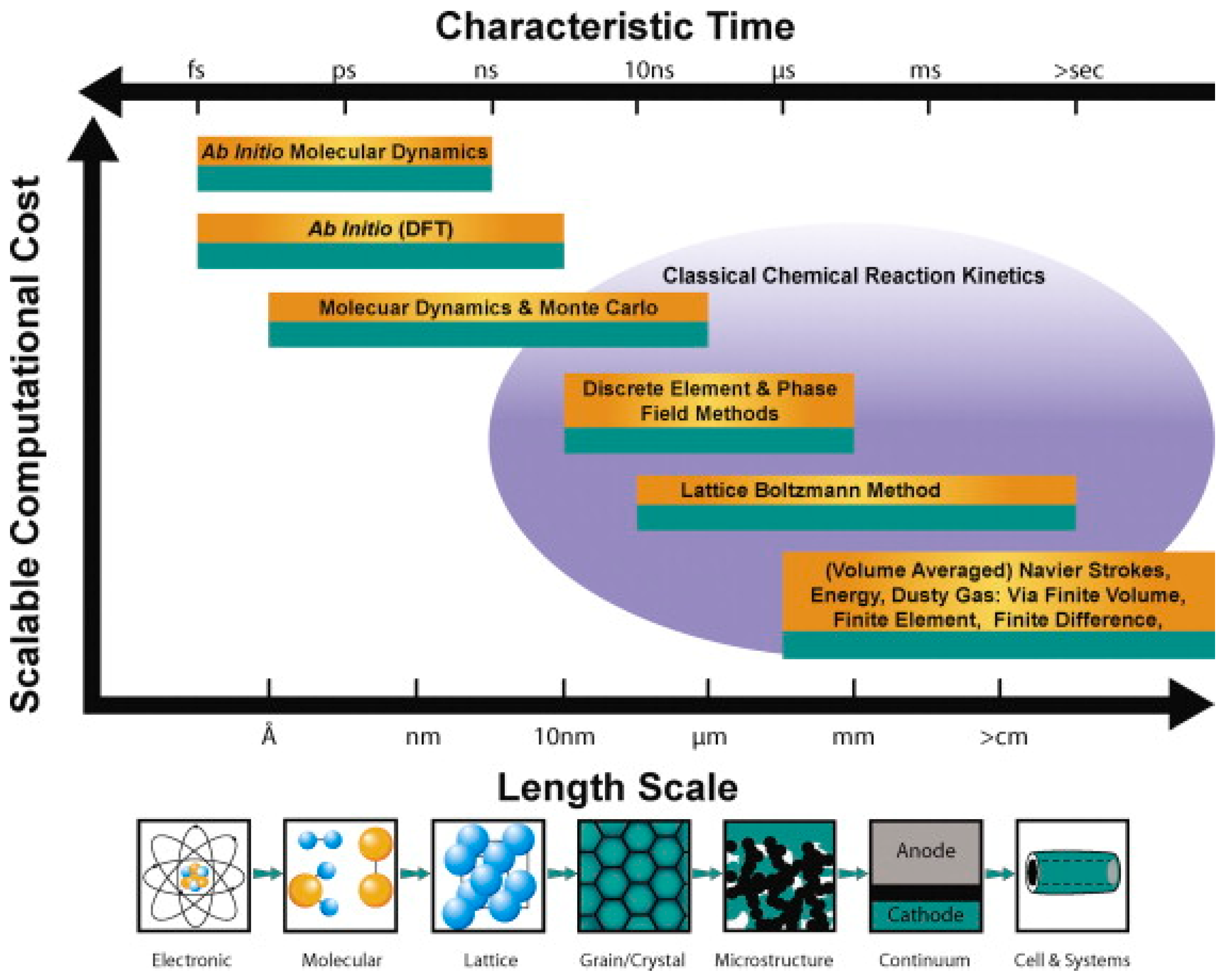
  109. Grew, K.N.; Chiu, W.K.S. A Review of Modeling and Simulation Techniques across the Length Scales for the Solid Oxide Fuel Cell. J. Power Sources 2012, 199, 1–13. [Google Scholar] [CrossRef]
  110. Fan, L.; Li, C.; Aravind, P.V.; Cai, W.; Han, M.; Brandon, N. Methane Reforming in Solid Oxide Fuel Cells: Challenges and Strategies. J. Power Sources 2022, 538, 231573. [Google Scholar] [CrossRef]
  111. Harun, N.F.; Tucker, D.; Adams, T.A., II. Impact of Fuel Composition Transients on SOFC Performance in Gas Turbine Hybrid Systems. Appl. Energy 2016, 164, 446–461. [Google Scholar] [CrossRef]
  112. Corigliano, O.; Fragiacomo, P. Extensive Analysis of SOFC Fed by Direct Syngas at Different Anodic Compositions by Using Two Numerical Approaches. Energy Convers. Manag. 2020, 209, 112664. [Google Scholar] [CrossRef]
  113. Zainon, A.N.; Somalu, M.R.; Kamarul Bahrain, A.M.; Muchtar, A.; Baharuddin, N.A.; Sa, M.A.; Osman, N.; Abdul Samat, A.; Azad, A.K.; Brandon, N.P. Challenges in Using Perovskite-Based Anode Materials for Solid Oxide Fuel Cells with Various Fuels: A Review. Int. J. Hydrogen Energy 2023, 48, 20441–20464. [Google Scholar] [CrossRef]
  114. Hadi, N.H.; Somalu, M.R.; Samat, A.A.; Muchtar, A.; Baharuddin, N.A.; Anwar, M. A Review on the Preparation of Anode Materials and Anode Films for Solid Oxide Fuel Cell Applications. Int. J. Energy Res. 2021, 45, 14357–14388. [Google Scholar] [CrossRef]
  115. Zeng, Z.; Qian, Y.; Zhang, Y.; Hao, C.; Dan, D.; Zhuge, W. A Review of Heat Transfer and Thermal Management Methods for Temperature Gradient Reduction in Solid Oxide Fuel Cell (SOFC) Stacks. Appl. Energy 2020, 280, 115899. [Google Scholar] [CrossRef]
  116. Pashchenko, D. Numerical Study of Steam Methane Reforming over a Pre-Heated Ni-Based Catalyst with Detailed Fluid Dynamics. Fuel 2019, 236, 686–694. [Google Scholar] [CrossRef]
  117. Varandas, B.; Oliveira, M.; Borges, A. Analytical and Numerical Thermodynamic Equilibrium Simulations of Steam Methane Reforming: A Comparison Study. Reactions 2024, 5, 246–259. [Google Scholar] [CrossRef]
  118. Pashchenko, D. Thermodynamic Equilibrium Analysis of Steam Methane Reforming Based on a Conjugate Solution of Material Balance and Law Action Mass Equations with the Detailed Energy Balance. Int. J. Energy Res. 2020, 44, 438–447. [Google Scholar] [CrossRef]
  119. Özkara-Aydınoğlu, Ş. Thermodynamic Equilibrium Analysis of Combined Carbon Dioxide Reforming with Steam Reforming of Methane to Synthesis Gas. Int. J. Hydrogen Energy 2010, 35, 12821–12828. [Google Scholar] [CrossRef]
  120. Pashchenko, D.; Mustafin, R.; Mustafina, A. Steam Methane Reforming in a Microchannel Reformer: Experiment, CFD-Modelling and Numerical Study. Energy 2021, 237, 121624. [Google Scholar] [CrossRef]
  121. Ngo, S.I.; Lim, Y.-I.; Kim, W.; Seo, D.J.; Yoon, W.L. Computational Fluid Dynamics and Experimental Validation of a Compact Steam Methane Reformer for Hydrogen Production from Natural Gas. Appl. Energy 2019, 236, 340–353. [Google Scholar] [CrossRef]
  122. Lao, L.; Aguirre, A.; Tran, A.; Wu, Z.; Durand, H.; Christofides, P.D. CFD Modeling and Control of a Steam Methane Reforming Reactor. Chem. Eng. Sci. 2016, 148, 78–92. [Google Scholar] [CrossRef]
Figure 1. General overview of SOFC principles. Reproduced with permission [2].
Physchem 05 00025 g001
Figure 2. Scenarios of using hydrocarbon fuel in SOFCs. Reproduced with permission [3].
Physchem 05 00025 g002
Figure 3. Schematic of an SOFC representing different components. Reproduced with permission [5].
Physchem 05 00025 g003
Figure 4. Outline for different fuel cell types using hydrogen and syngas produced by processing of gaseous, liquid, and solid fuels. Reproduced with permission [6].
Physchem 05 00025 g004
Figure 5. Global Greenhouse Gas Emission. Reproduced with permission [8].
Physchem 05 00025 g005
Figure 6. Schematic of the integration of the gasification technology with the supercritical water technology. Reproduced with permission [11].
Physchem 05 00025 g006
Figure 7. Schematic process flowsheet for hydrogen production using SMR.
Physchem 05 00025 g007
Figure 8. Equilibrium conversions for a constant methane/(CO2 + H2O) molar ratio of unity. (♦) methane; (■) CO2 (T = 800 °C, P = 1 bar). Reproduced with permission [16].
Physchem 05 00025 g008
Figure 9. Equilibrium CH4 conversions at different temperatures and feed ratios, measured by thermodynamic calculation. Reproduced with permission [6].
Physchem 05 00025 g009
Figure 10. Process flow diagram of DMR for CO/H2 production. Reproduced with permission [17].
Physchem 05 00025 g010
Figure 11. Comparison of common metal-based catalysts for SMR reaction. Reproduced with permission [20].
Physchem 05 00025 g011
Figure 12. Ideal structures of perovskite catalysts for methane reforming. Reproduced with permission [22].
Physchem 05 00025 g012
Figure 13. Essential cathode/anode material properties. Reproduced with permission [48].
Physchem 05 00025 g013
Figure 14. Different chemicals produced from syngas. Reproduced with permission [61].
Physchem 05 00025 g014
Figure 15. Thermodynamic simulations of BRM reaction at P = 1 bar for a wide range of temperatures. Reproduced with permission [71].
Physchem 05 00025 g015
Figure 16. Methane consumption rate (mol·s−1kg−1metals) during reforming tests of a gas mixture including 7 ppm H2S at 1173 K and a total pressure of 101.3 kPa. Reproduced with permission [78].
Physchem 05 00025 g016
Figure 17. (A) Schematic of the SOFC; (B) the cross-sectional SEM of the button cell. Reproduced with permission [88].
Physchem 05 00025 g017
Figure 18. Suggested mechanism for superior catalytic performance and excellent capability of bond cleavage on the LCFNb–SDC–Ni composite anode. Reproduced with permission [101].
Physchem 05 00025 g018
Figure 19. Microstructure parameters and simulation approaches applicable for the SOFCs, where the poor prediction accuracy of RSM is plotted versus the time and length scales that can be resolved. Reproduced with permission [109].
Physchem 05 00025 g019
Figure 20. The principal reactions leading to coke formation on a typical Ni-YSZ anode. Reproduced with permission [110].
Physchem 05 00025 g020
Figure 21. Sulphur poisoning mechanism. Reproduced with permission [110].
Physchem 05 00025 g021
Figure 22. Product and reactant concentration profiles used directly in SOFCs at the initial steady state operating on syngas. Reproduced with permission [111].
Physchem 05 00025 g022
Table 1. Summary of perovskite type catalysts for methane reforming.
CatalystReaction ConditionsPerformanceStabilityReferences
Ru+Ni/LaPrMnCrFeed (18%CH4 + 36%H2O in Ar), residence time = 0.08 s, T = 750 °CConcentration % (CH4 = 3.9, CO2 = 4, CO = 8.5, H2 = 40)Stability testing of the Ni/YSZ anode was carried out at 650 °C for 26 h[24]
Ni/CaTiO3Feed (CH4:O2:H2O = 2:1:0.3), using 60 mg of mixture Si/catalyst (5:1), T = 800 °C and atmospheric pressureSelectivity % (H2 = 49, CO = 89, CO2 = 10),
CH4 Conversion (%) = 72
24 h as the reaction time[25]
Ni/BaTiO3Feed (CH4:O2:H2O = 2:1:0.3), using 60 mg of mixture Si/catalyst (5:1), T = 800 °C and atmospheric pressureSelectivity % (H2 = 49, CO = 92, CO2 = 8),
CH4 Conversion (%) = 72
24 h as the reaction time[25]
Ni/SrTiO3Feed (CH4:O2:H2O = 2:1:0.3), using 60 mg of mixture Si/catalyst (5:1), T = 800 °C and atmospheric pressureSelectivity % (H2 = 38, CO = 85, CO2 = 12)
CH4 Conversion (%) = 51
24 h as the reaction time[25]
Ce1.0Al0.98Rh0.02O3−ẟGHSV = 34,900 h−1, S/C = 1.2 and O2/C = 0.79, T = 650 °CYield % (H2 = 60, CO = 31, CO2 = 10),
CH4 Conversion (%) = 75
-[26]
Ce1.0Al0.975Rh0.02Pt0.005O3−ẟGHSV = 34,900 h−1, S/C = 1.2 and O2/C = 0.79, T = 650 °CYield % (H2 = 72, CO = 25, CO2 = 7),
CH4 Conversion (%) = 100
The stability test carried out over 72 h at 650 °C[26]
La0.9Ce0.1NiO3T = 800 °C, GHSV = 10,000 hr−1, CO2/CH4 = 1, atmospheric pressureSelectivity % (H2 = 61, CO = 49),
Conversion %
(CO2 = 93, CH4 = 92)
Stability during the CO2 reforming with methane over 22 h[27]
Table 2. Electrochemical performances of differently fueled SOFCs.
Cell Configuration (Catalyst/Anode/Electrolyte/Cathode)FuelOperating Temperature (°C)Max Power Density (W/cm2)Long-Term Stability TestReferences
BZYNR/Ni-YSZ/YSZ-GDC/LSCFIso-octane6500.20500 h[31]
Co-Fe/SFMCo-SDC/SDC97%C3H8-3%H2O8000.1565 h[32]
Ru-Al2O3/NiO-YSZ/LSM-YSZ80%CH4-20%O27500.7400 min[33]
NiTiO3/NiO-YSZ/YSZ/LSM-YSZ3%H2O-CH47000.2390 h[34]
LSFM-CeO2/BZCY/LSFM-CeO2C2H67500.1822 h[35]
Cr3C2/BCZY/LSFC2H67500.1880 h[36]
Cu-Ni-SDC/YSZ/SDC/LSCFCH47000.4215 h[37]
Ni0.875Cu0.1Mg0.025O-SDC/SDC/LSCF-SDC3%H2O-CH47000.67100 h[38]
Pd-infiltrated Ni-YSZ/Ni-YSZ/YSZ/GDC/LSCButane–steam mixture (S/C: 3)6000.94100 h[39]
BaO-deposited Ni-YSZ/YSZ/SDC/LSCFPropane7500.88100 h[40]
P-PSCFM/BCZY/GDC/LSCF-BCZYEthane7500.34100 h[41]
LSFNCu/BZCYYb/LSFNCuEthane7500.0940 h[42]
Cu-CeO2-ScSZ/ScSZ/PCMEthanol–steam mixture (volume ratio: 2:1)8000.2250 h[43]
Ni-BZCYYb/SDC/BSCFEthanol6000.51100 h[44]
Ba-Ni-YSZ/Ni-YSZ/YSZ/LSM-YSZAmmonia–nitrogen mixture7500.2550 h[45]
Ni97Cr3-SDC/LSGM/SSCAmmonia–nitrogen mixture6000.1430 h[46]
Table 3. Disadvantages and advantages of the recent advanced reforming approaches.
ProcessSMRPOMDMRBRM
Reaction C H 4 + H 2 O C O + 3 H 2 ( H 298 K 0 = 206   k J m o l 1 ) C H 4 + 1 / 2 O 2 C O + 2 H 2 ( H 298 K 0 = 38   k J m o l 1 ) C H 4 + C O 2 2 C O + 2 H 2 ( H 298 K 0 = 248   k J m o l 1 ) 3 C H 4 + C O 2 + 2 H 2 O 4 C O + 8 H 2 ( H 298 K 0 = 712 k J m o l 1 )
StrengthHigh efficiency and industrially established technology with the highest hydrogen selectivity.Identifies the process parameters influencing the lifetime of the adsorbent bed and the degree of the bed conversion.Efficient greenhouse gases consumption and favorable syngas ratio for FTS.Flexible syngas ratios and minimum carbon deposition.
WeaknessHigh emission of carbon dioxide and need for a desulfurization unit, together with severe heat duty.Pollutants are degraded by specific bacteria which grow on a wet inorganic solid packing material.Quick catalyst deactivation due to carbon formation and active sites sintering, while also being energy intensive (highly endothermic).High process temperature requirements and challenging for large-scale production
Operating conditionsT(°C) = 700–1000; P(bar) = 3–25; CH4/H2O = 1/1T(°C) = 950–1100; P(bar) = 100; CH4/O2 = 2/1T(°C) = 650–850; P(bar) = 1; CH4/CO2 = 1/1T(°C) = 500–1000; P(bar) = 1; CH4/H2O/CO2 = 3/2/1
H2/CO ratio>32<12
Table 4. Catalytic activity of different catalysts in various SRM.
CatalystPreparation MethodType of ReactorReaction ConditionCatalytic ActivityReference
Ni/SiO2 (NS)Incipient wetness impregnationFixed bedT = 500 °C, P = 1 bar, Wcat = 0.1 g, H2O/CH4 = 2.CH4 conv. = 86%[18]
Ni/Calcium aluminateWet impregnationPacked bedT = 546 °C, P = 1 bar, Wcat = 0.1 g, H2O/CH4 = 4.CH4 conv. = 85%[57]
5wt%Ni/ZrO2Wet impregnationFixed bedT = 500 °C, P = 1 bar, Wcat = 0.3 g, H2O/CH4 = 2.CH4 conv. = 15.6%[58]
Unsupported nickelThermal decompositionSeven-cell differentialT = 700 °C, P = 1 bar, Wcat = 0.25 g, H2O/CH4 = 2.CH4 conv. = 95%[59]
Table 5. Different catalyst systems used for POM in the literature.
CatalystTemperature (°C)Weight Hourly Space Velocity (mL h−1 gcat−1)Conversion CH4 (%)H2/CO RatioReference
Pt/Al2O38001–2 × 10563-[62]
LaNi1−xNbxO3 (x = 0,0.5)750 201.4[63]
Ni/MgAl2O4-2800157,500 Lkg−1h902[64]
Co/Mg-Al800300 LN CH4/(gcat h)91.32[65]
Co-Ni-Ru8001 × 104 h−198.72[66]
Table 6. Conversion efficiencies of methane and carbon dioxide obtained for different catalysts.
CatalystsCH4/H2O/CO2 RatioTemperature (°C)GHSV
(L gcat−1h−1)
TOS (h)Conversion (%)Reference
CH4CO2
5 wt% Ni/Mg0.75Al0.25O15/0.012/68006.30.56358[72]
10 wt% Ni/SBA-153/2/180036-6258[73]
Table 7. Examples of gas–solid reactions leading to catalyst deactivation.
Catalytic ProcessGas/Vapor CompositionCatalytic MaterialDeactivation Chemical ReactionReference
Steam reformingVarious concentrations of H2S in the range of 20–150 ppm.Ni-based catalystThe deactivation of Ni/Al2O3 due to sulfur poisoning.[74]
Fischer–Tropsch SynthesisH2/CO = 2 at 493 K, 20 barCo/TiO2 catalystLoss of active metal surface area and particle growth are the most important factors.[75]
Table 8. The mixture of different types of thermodynamic reactions at the DIR–SOFC anode [80].
Electrochemical ReactionEquationType of Reaction
Methane dry reforming C H 4 + C O 2 2 C O + 2 H 2 Endothermic
Methane full dry reforming C H 4 + C O 2 + O 2 2 C O + 2 H 2 O Endothermic
Reverse water–gas shift C O + H 2 O C O 2 + H 2 Exothermic
Methane pyrolysis/cracking C H 4 C + 2 H 2 Endothermic
Hydrogen oxidation H 2 + 0.5 O 2 H 2 O H 2 + O 2 H 2 O + 2 e Exothermic
CO oxidation C O + 0.5 O 2 C O 2 Exothermic
SMR C H 4 + H 2 O C O + 3 H 2 Endothermic
CH4 full steam reforming C H 4 + 2 H 2 O + O 2 C O 2 + 4 H 2 Endothermic
CO2 carbon gasification C O 2 + C 2 C O + C g Endothermic
Steam carbon gasification C + H 2 O C O + 2 H 2 Endothermic
Boudouard reaction C + C O 2 2 C O Endothermic
Steam full carbon gasification C H 4 + 2 H 2 O + C O 2 4 C O + 2 H 2 Endothermic
CH4 partial oxidation C H 4 + 0.5 O 2 C O + 2 H 2 Exothermic
CH4 full oxidation C H 4 + 2 O 2 C O 2 + 2 H 2 O Exothermic
Carbon oxidation C + 0.5 O 2 C O C O + O 2 C O 2 + 2 e Exothermic
Carbon steam methanation 2 C + 2 H 2 O C O 2 + C H 4 Endothermic
Carbon full steam methanation C + 2 H 2 O C O 2 + 2 H 2 Endothermic
Table 9. Performance comparison of SOFCs in a direct internal steam reforming operation over methane and ethanol.
Anode MaterialOperating Temperature (°C)Gas CompositionPPD (mW/cm2)
Current (mA/cm2)
Degradation rate@ j mAcm−2RemarksRef.
Ni-YSZ-CeO2700–1000S/C = 2–7Current = 600 CH4 conversion = 15%[81]
Ni/SDC600–750S/C = 1Power density = 0.19–0.42 A/cm2 CH4 conversion = 53–28%[82]
NiO–SDC700–1000S/C = 1.2–2Current = 0.2 Acm2 CH4 conversion = 1–40%[83]
Ni/YSZ750–850Steam/ethanol = 7Current density = 0.79 A/cm2; Power density = 0.51 W/cm2 Fuel-cell efficiency = 27.5%[84]
Ni/YSZ80017.10% CH4, 2.94% CO, 4.36% CO2, 26.26% H2 and 49.34% H2OCurrent density = 7888 A/m2; Power density = 5747 W/A2 Fuel cell efficiency = 46–62%[85]
Ni/YSZ750S/C = 1 (20% H2O-20% CH4)Current density = 0.3 A/cm2; Power density = 5747 W/m2Vde(/1000 h) = 1.10%CH4 conversion = 45%[86]
Table 10. Functional anode materials for SOFCs.
Catalyst LayerPreparation MethodFuelAnode SupportTemperature (°C)PPD
(mW cm−2)
Durability (h)Reference
Ni-CeO2Mixed mechanicalMethaneNi-SDC60016020[89]
Ru/CeO2ImpregnationIso-octaneNi-YSZ77060050[90]
Ni-BaO-CeO2/SiO2Sol–gelMethane-airNi-YSZ800830180[91]
Ir-CGOIncipient wetness impregnationEthanol-airNi-YSZ850420600[92]
PdGalvanic displacement reactionEthanolNi-YSZ75019659[93]
Ce0.8Ni0.2O2−δSol–gelWet methaneNi-SDC65066440[94]
CeO2-BaO-NiO/SiO2Sol–gelCH4/airNi-YSZ800938163[95]
Ni/Al2O3Dual dry pressing/sinteringCH4/O2Ni-ScSZ85038225[96]
(Rh, Pt, and Pd)-GDCCo-impregnationCH4/H2ONi-zirconia8001501000[97]
GdNi-Al2O3Sol–gelCH4Ni-YSZ8501068300[98]
Ru-Al2O3Glycine nitrite process (GNP)CH4/O2Ni-YSZ85092910[33]
Table 11. Summary of SOFC anode performance improvements achieved by impregnation techniques.
Backbone (Anode)InfiltrateCell ConfigurationPerformance of Infiltrate/Baseline (Rp, Ω cm2; Pmax, W cm−2)Temperature (°C)Ref
Ni/YSZ;
Ni/MIEC
Ni, GDC, Ni/GDC
Ni
SymmetricRp (no infiltrate) = 1.95
Rp (Ni) = 0.97
Rp (GDC) = 0.02
Rp (Ni-GDC) = 0.01
Rp (Ni) = 0.97
Rp (no infiltrate) = 4.86
Rp (Ni) = 0.65
800[103]
YSZ0.5–1 wt% Pd, Rh, or NiSymmetricPmax = 500 mW/cm2700[104]
CeO2La0.3Sr0.7Ti0.3Fe0.7O3−δSymmetricRp,a (Ωcm2) = 0.086;
Rp,c (Ωcm2) = 0.38;
MPD (mWcm−2) = 612
800[105]
Ni/YSZ2 wt% PdO MPD (Wcm−2) = 0.792; degradation rate = 3.75 mVh−1 in 40 h600[39]
Disclaimer/Publisher’s Note: The statements, opinions and data contained in all publications are solely those of the individual author(s) and contributor(s) and not of MDPI and/or the editor(s). MDPI and/or the editor(s) disclaim responsibility for any injury to people or property resulting from any ideas, methods, instructions or products referred to in the content.

