Experimental and Numerical Investigation of Shear Performance of RC Deep Beams Strengthened with Engineered Cementitious Composites


Abstract
1. Introduction
Research Gap and Significance
2. Experimental Investigation
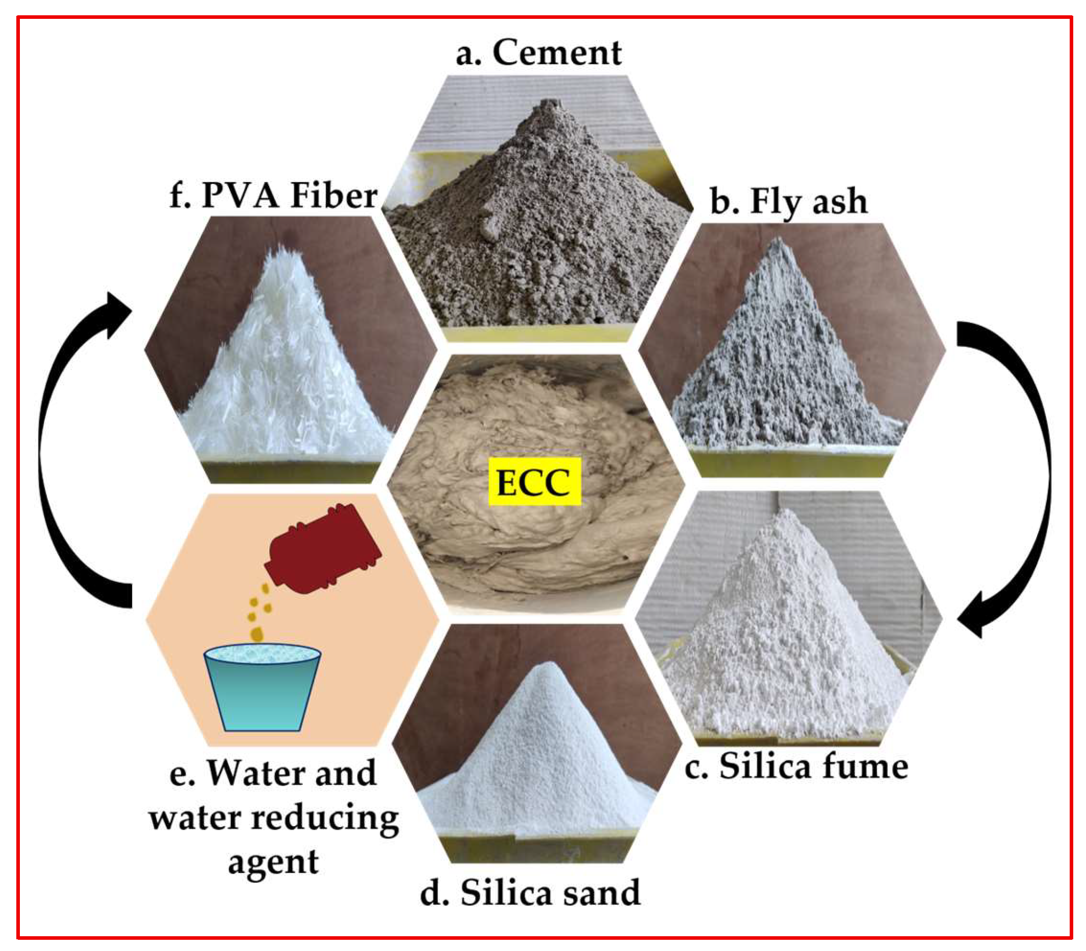
2.1. Materials
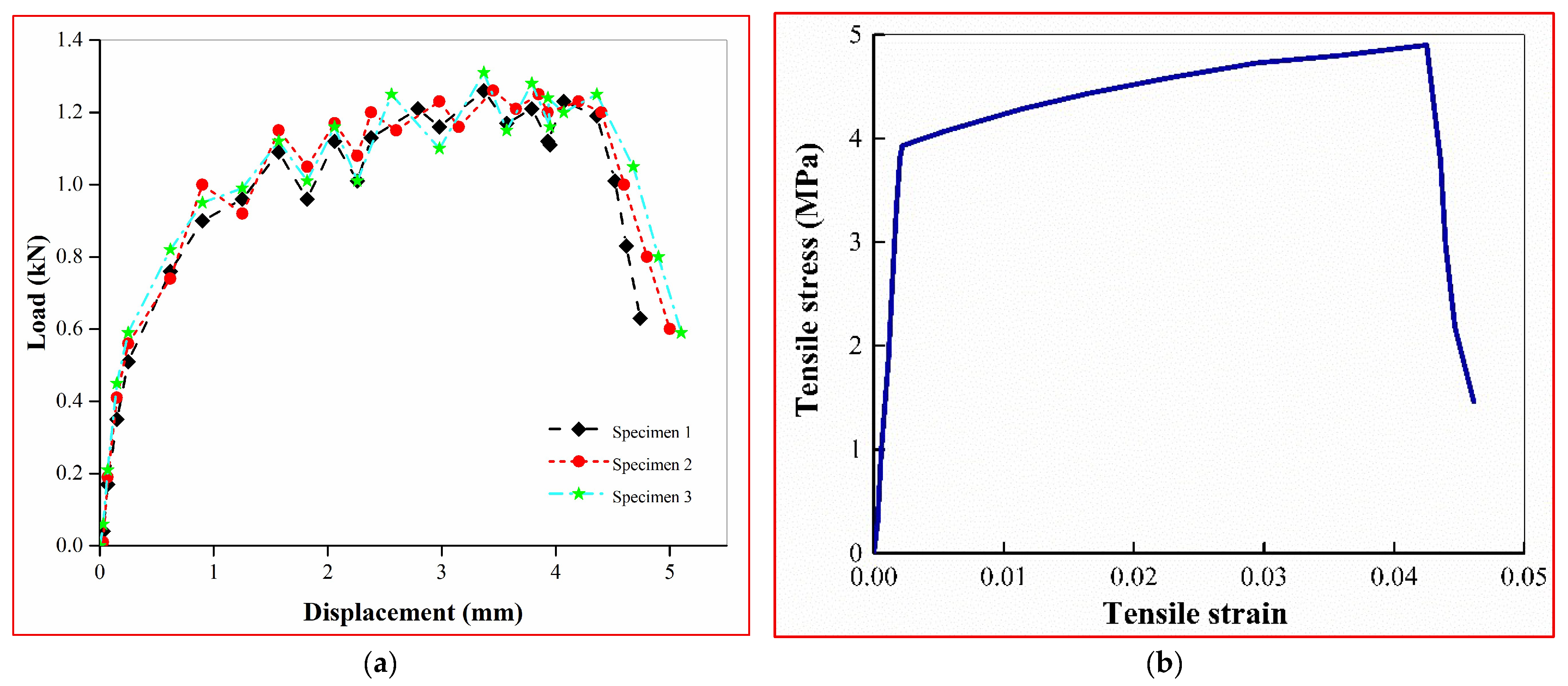
2.2. Mix Proportion, Preparation and Testing of ECC
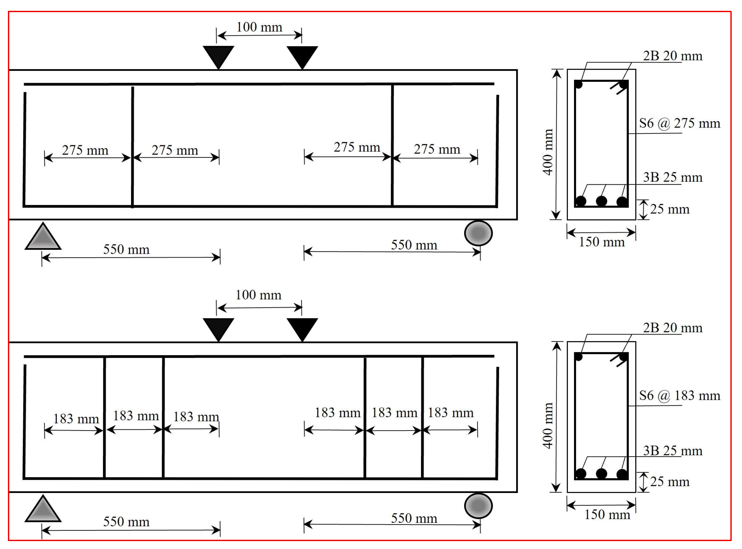
2.3. Details of Deep Beam Specimens
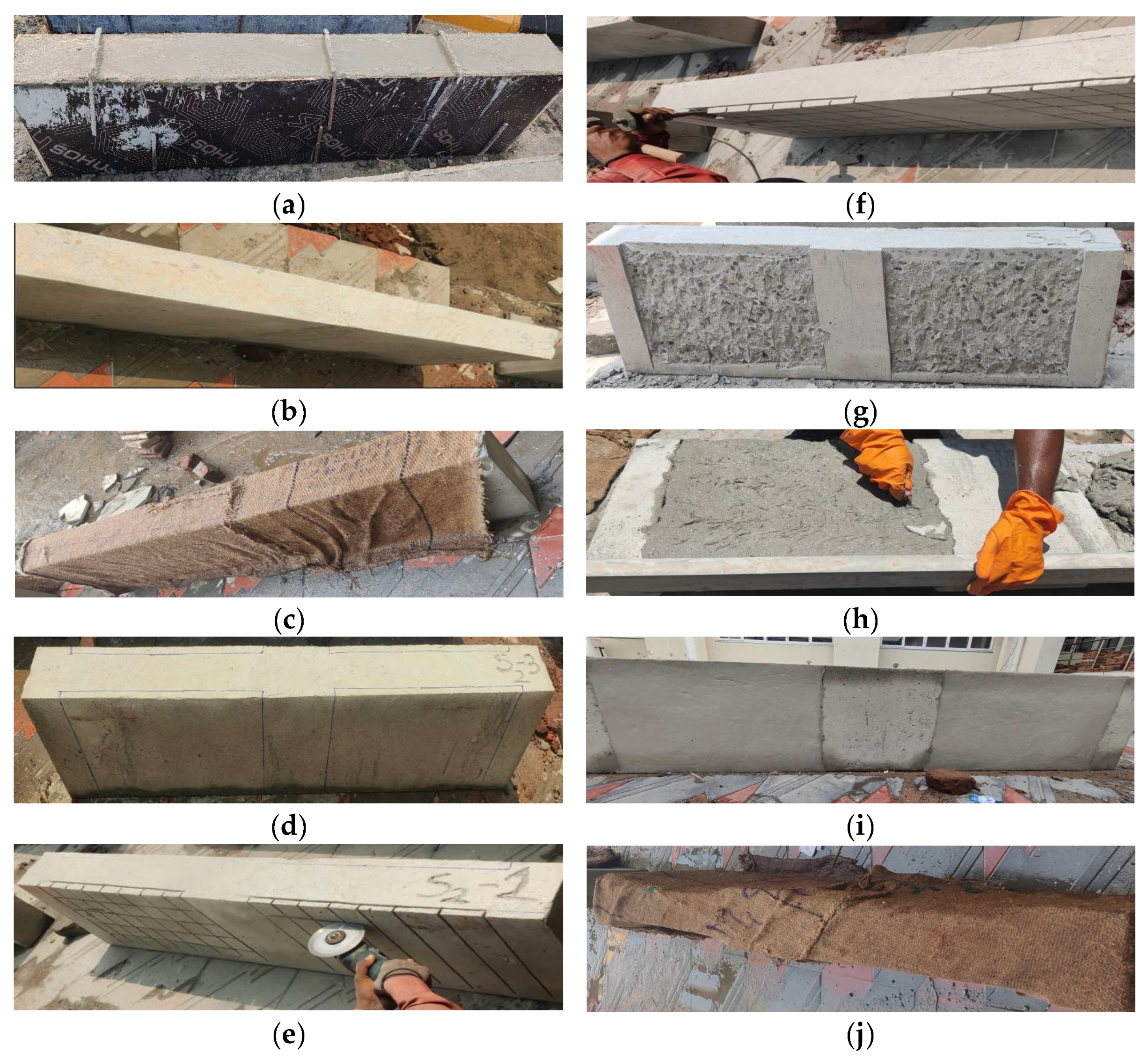
2.4. Strengthening Procedure
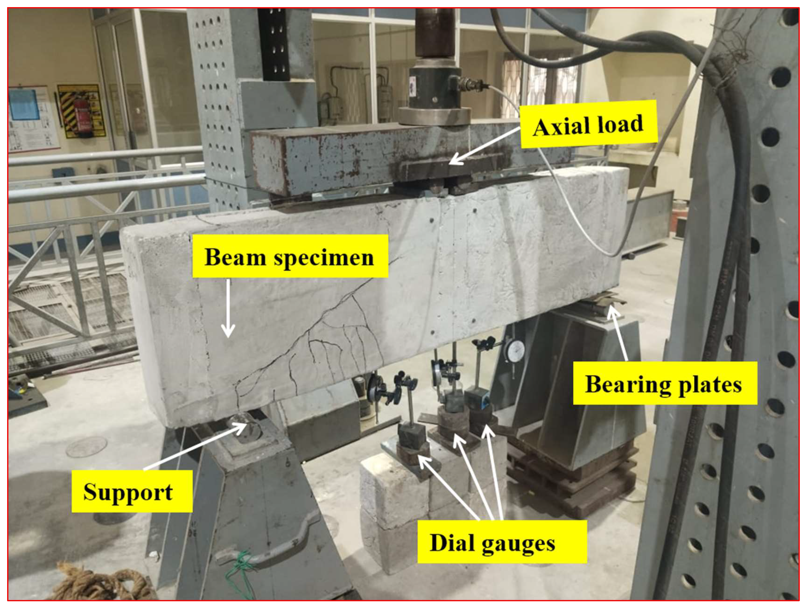
2.5. Experimental Test Setup
2.6. Results and Discussions
2.6.1. Load-Carrying Capacity
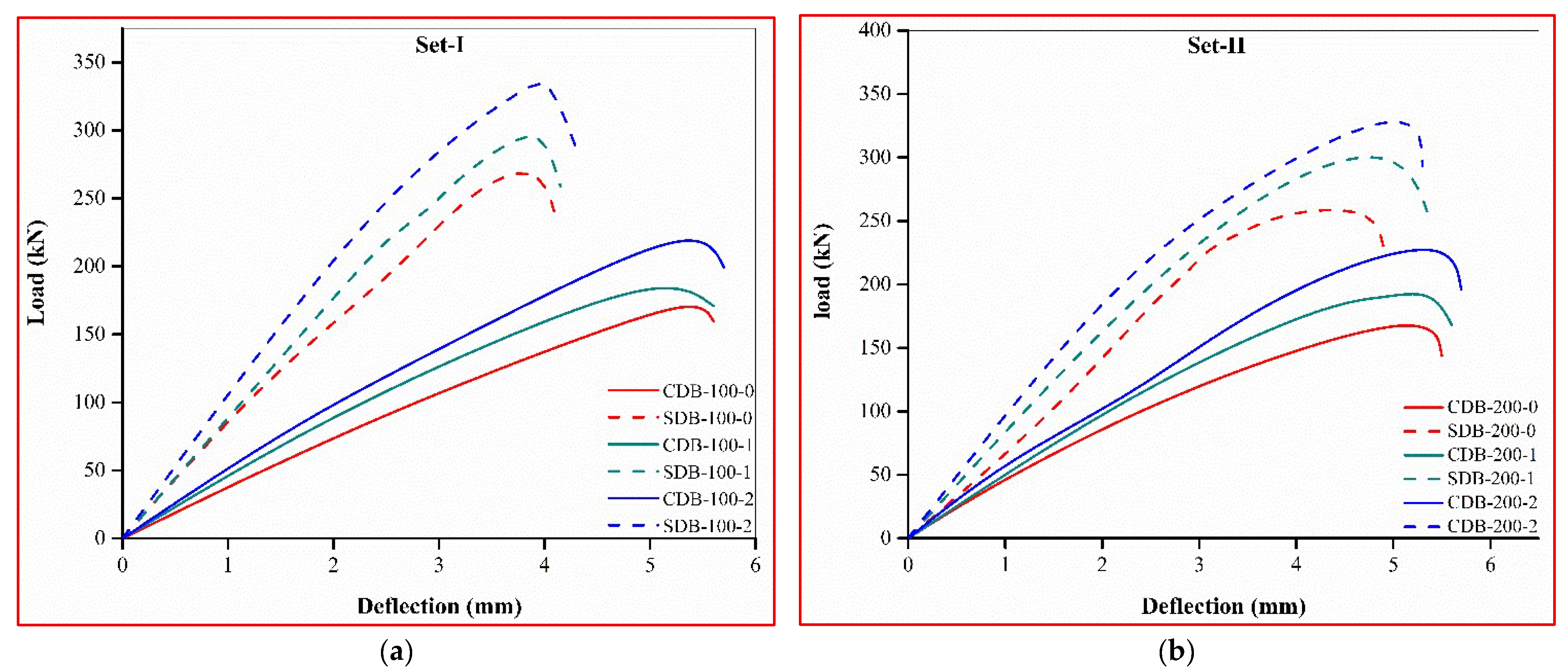
2.6.2. Load–Deflection Characteristics and Ductility Index
2.6.3. Crack Patterns and Failure Mode
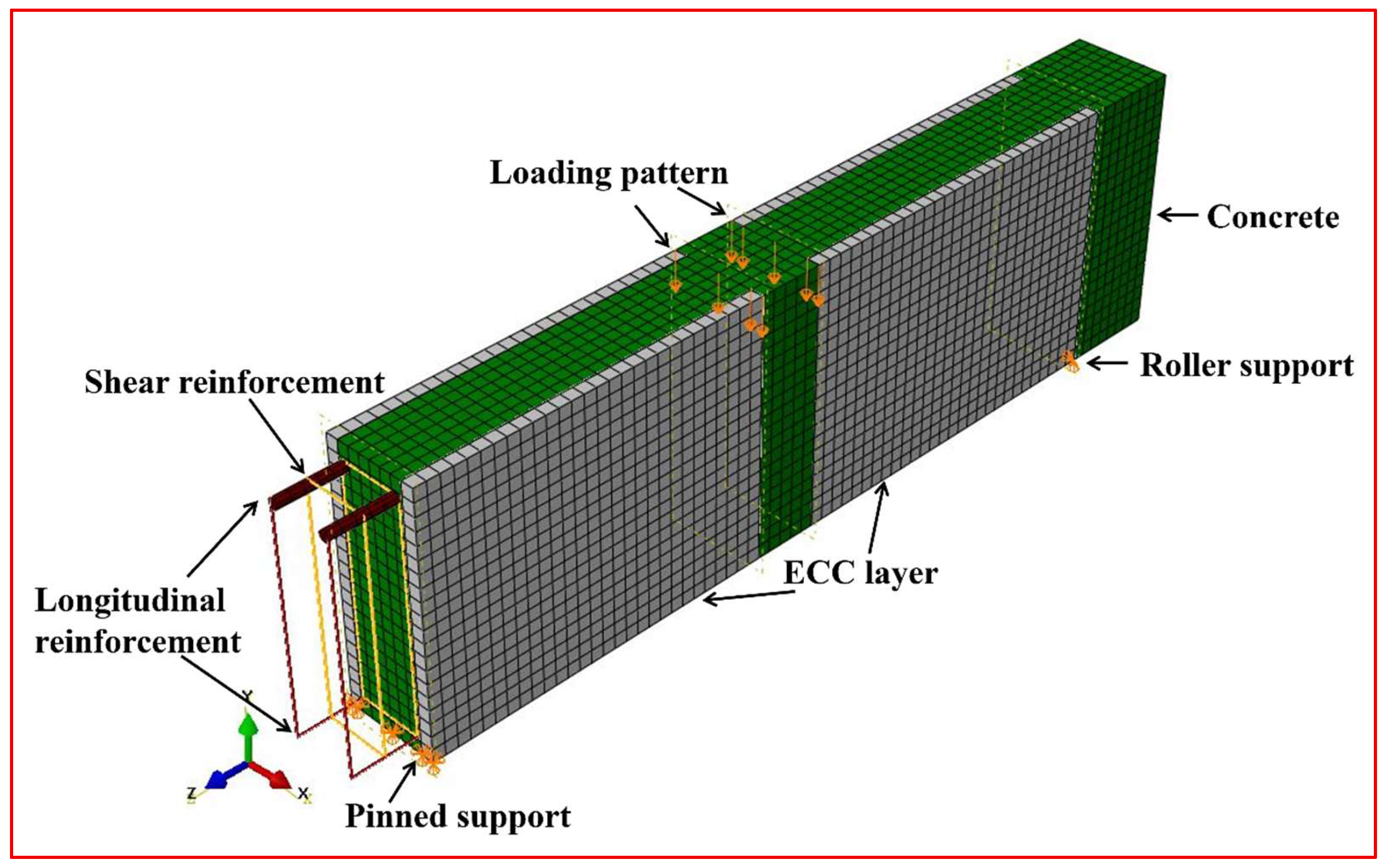
3. Numerical Investigation
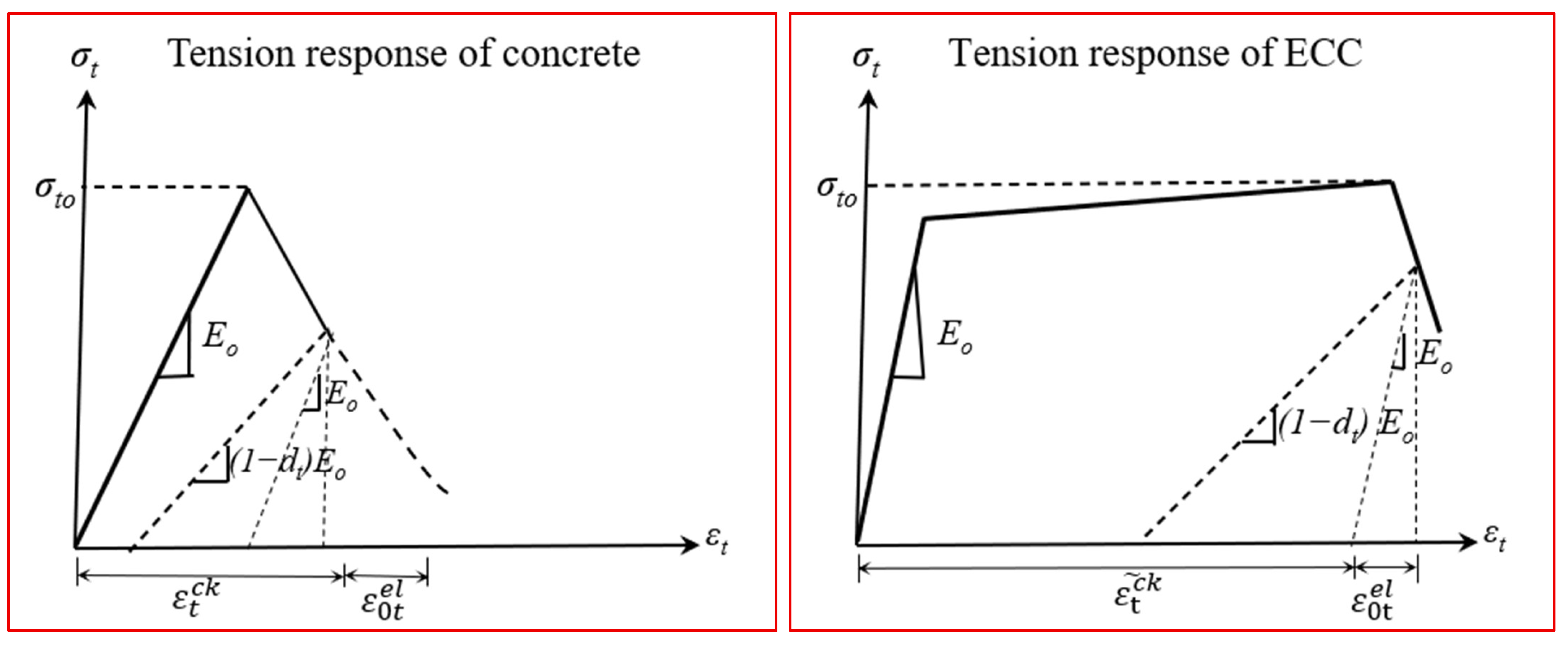
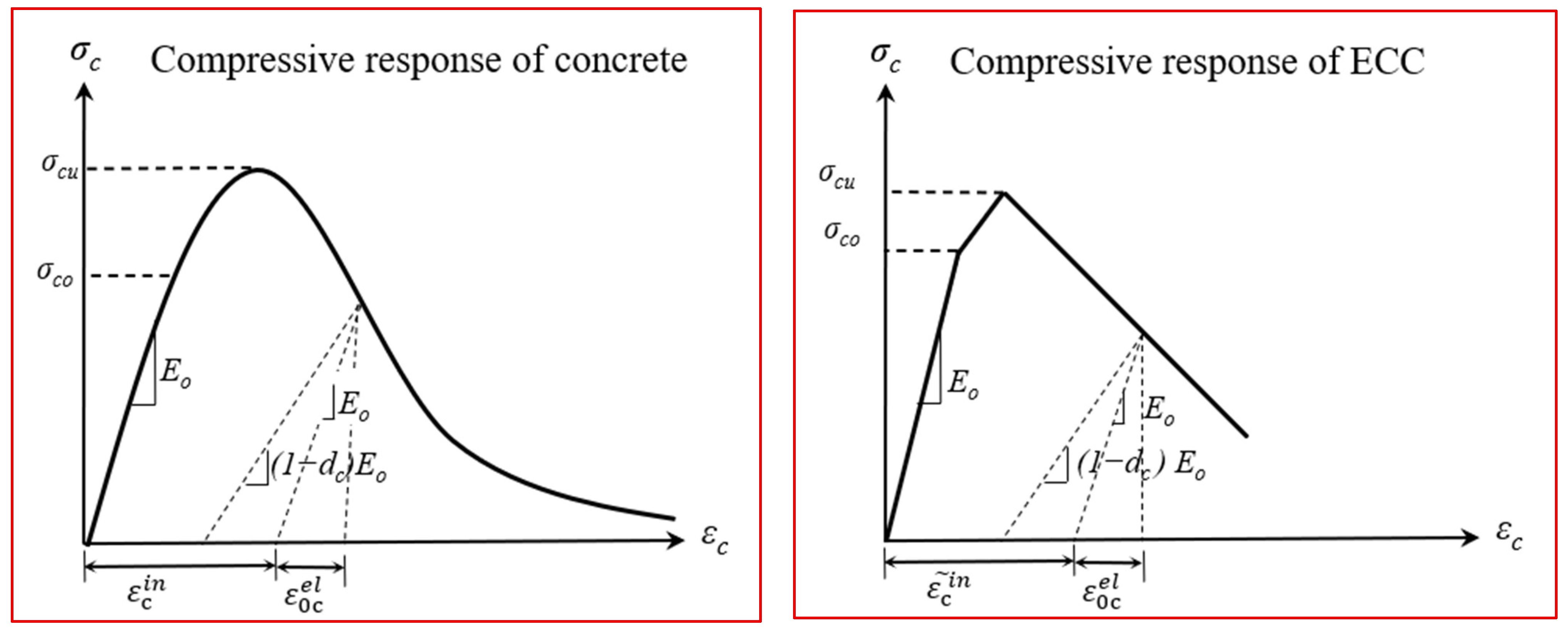
3.1. Non-Linear Finite Element Evaluation
- is the peak compressive yield stress, which takes values between zero and one.
- is the instantaneous compressive yield stress.
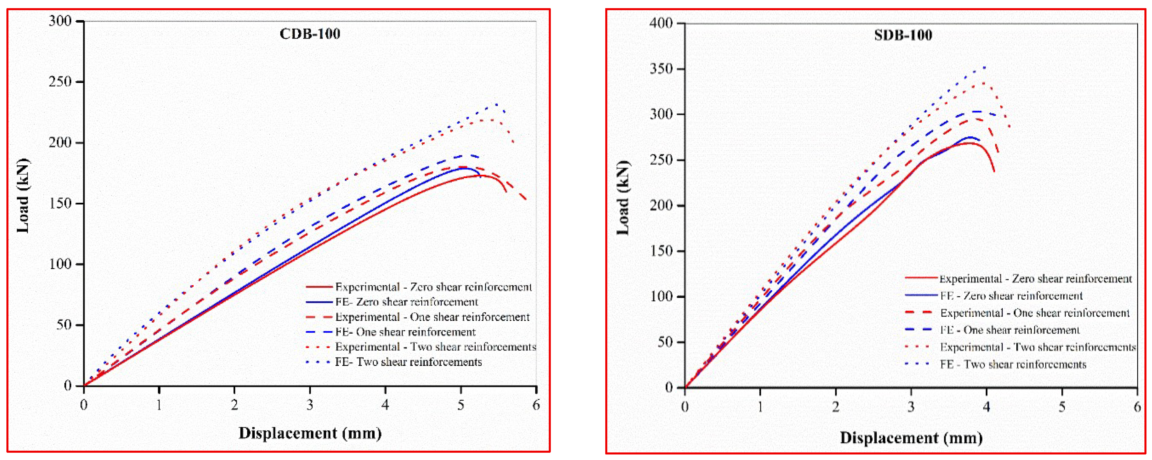
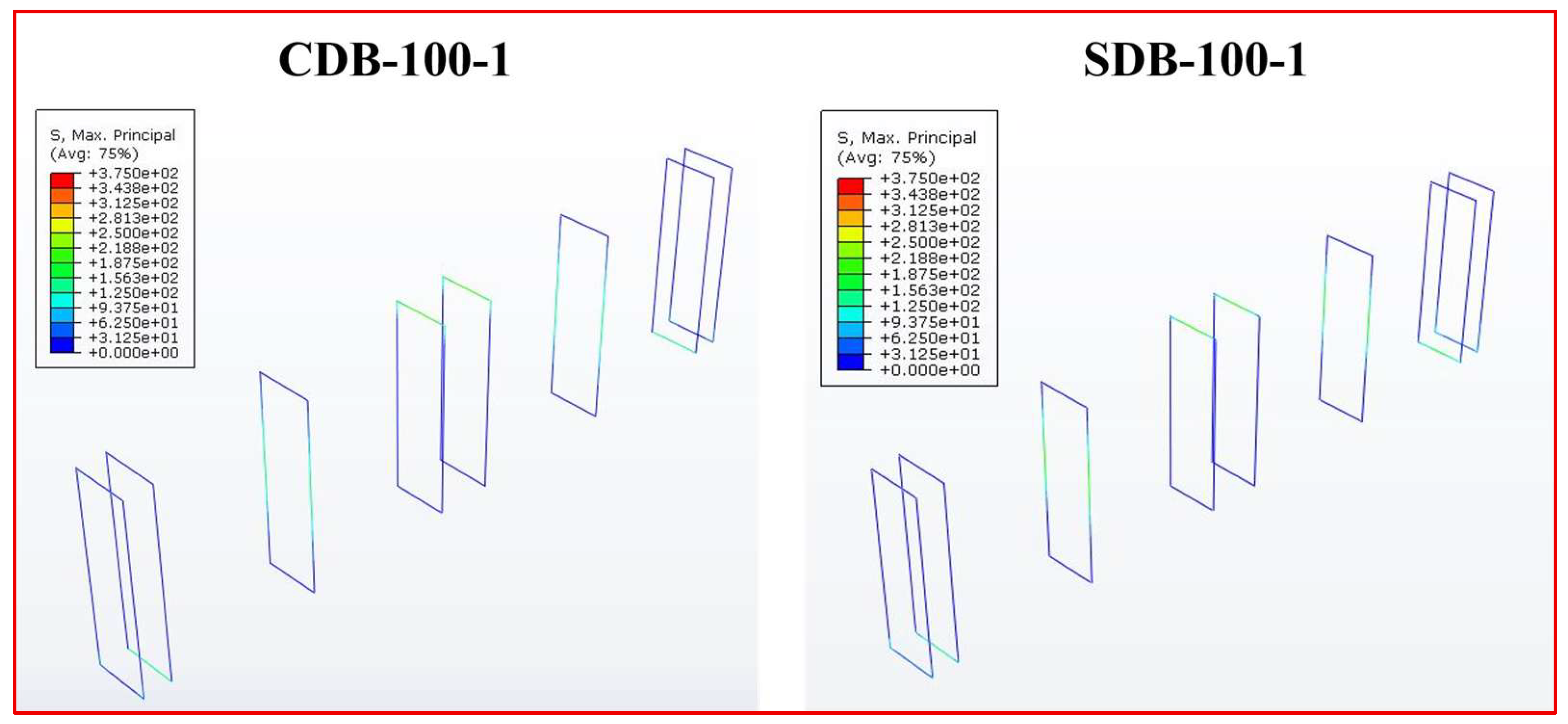
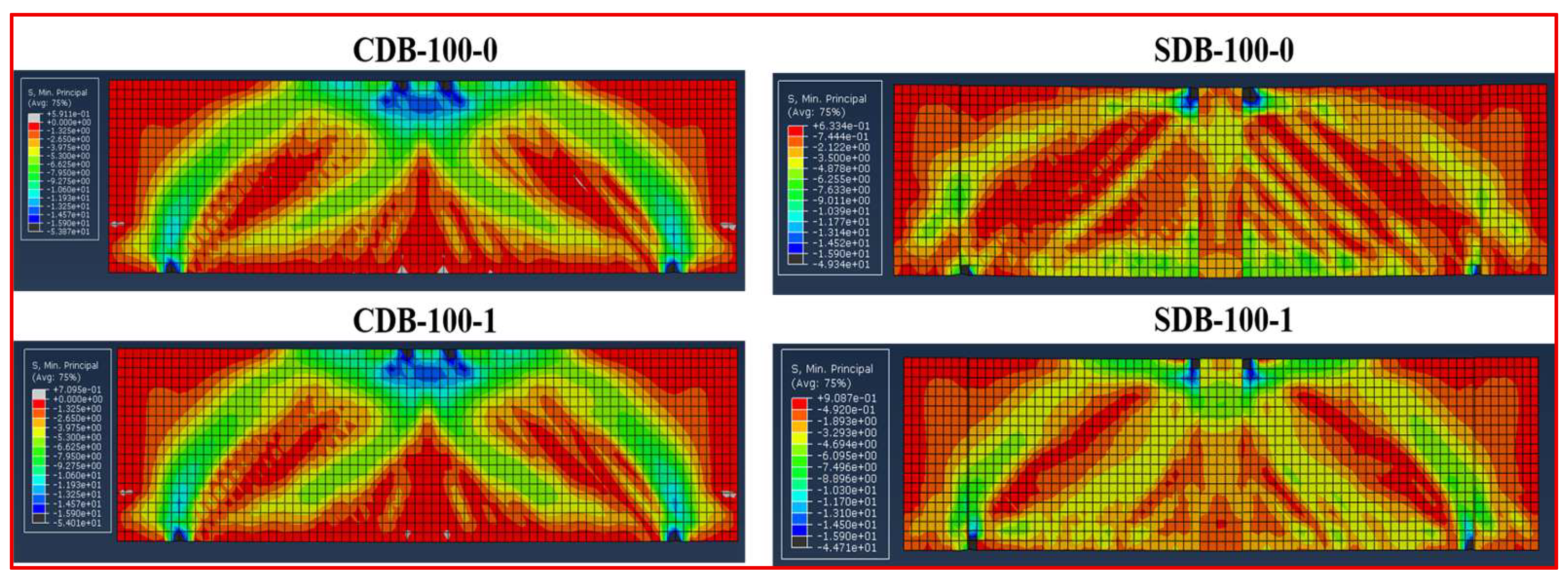
3.2. Verification and FE Results
4. Evaluation of Shear Capacity Using the Strut-and-Tie Method
- is the effective compressive force;
- is the total tie force;
- is the angle between the concrete strut and longitudinal reinforcement.
5. Conclusions
- The inclusion of a 20 mm ECC layer along the shear zone of RC deep beams increased the peak load-carrying capacity by up to 54.7% compared to unstrengthened control beams. This improvement was accompanied by enhanced ductility and a shift in failure mode from brittle diagonal splitting to ductile, distributed cracking.
- Increasing the number of vertical shear reinforcements further improved the shear capacity of the ECC-strengthened beams, confirming the combined effect of ECC and transverse reinforcement in enhancing structural performance.
- Finite element analysis using the Concrete Damaged Plasticity (CDP) model accurately predicted the load–deflection response, with an average error of 6.32% relative to experimental results. Stress analysis showed that ECC contributed to reducing stress concentrations, with longitudinal and shear reinforcements remaining below yield at peak load.
- The strut-and-tie method offered a simplified approach for shear capacity estimation but exhibited minor deviations in predicting peak load in ECC-strengthened specimens due to its limitations in modelling tensile and non-linear material behaviors.
- This multi-level approach combining experimental, numerical, and analytical methods confirmed the effectiveness of ECC layers in enhancing shear performance, providing valuable data for developing reliable strengthening strategies, particularly in structures built with low-strength concrete.
- Although direct cost–benefit analysis was not conducted, based on the literature, ECC offers long-term advantages in terms of durability, crack control, and reduced maintenance. Future research should incorporate life-cycle cost analysis and long-term durability assessments to support practical implementation of ECC strengthening systems.
Author Contributions
Funding
Data Availability Statement
Conflicts of Interest
References
- Demir, A.; Caglar, N.; Ozturk, H. Parameters Affecting Diagonal Cracking Behavior of Reinforced Concrete Deep Beams. Eng. Struct. 2019, 184, 217–231. [Google Scholar] [CrossRef]
- American Concrete Institute Committee 318. Building Code Requirements for Structural Concrete (ACI 318-14) and Commentary (ACI 318R-14); American Concrete Institute: Farmington Hills, MI, USA, 2014. [Google Scholar]
- Ashour, A.F. Shear Capacity of Reinforced Concrete Deep Beams. J. Struct. Eng. 2000, 126, 1045–1052. [Google Scholar] [CrossRef]
- Chalioris, C.; Kosmidou, P.-M.; Papadopoulos, N. Investigation of a New Strengthening Technique for RC Deep Beams Using Carbon FRP Ropes as Transverse Reinforcements. Fibers 2018, 6, 52. [Google Scholar] [CrossRef]
- Chai, K.F.; Woon, K.S.; Wong, J.K.; Lim, J.H.; Lee, F.W.; Lee, Y.L. Experimental and Numerical Study of the Strength Performance of Deep Beams with Perforated Thin Mild Steel Plates as Shear Reinforcement. Appl. Sci. 2023, 13, 8217. [Google Scholar] [CrossRef]
- Zheng, A.; Liu, Z.; Li, F.; Li, S. Experimental Investigation of Corrosion-Damaged RC Beams Strengthened in Flexure with FRP Grid-Reinforced ECC Matrix Composites. Eng. Struct. 2021, 244, 112779. [Google Scholar] [CrossRef]
- Maruta, M.; Kanda, T.; Nagai, S.; Yamamoto, Y. New High-Rise RC Structure Using Pre-Cast ECC Coupling Beam. Concr. J. 2005, 43, 18–26. [Google Scholar] [CrossRef]
- Kanakubo, T.; Shimizu, K.; Kanda, T.; Nagai, S. Evaluation of Bending and Shear Capacities of HPFRCC Members Toward the Structural Application. In Proceedings of the High Performance Fiber Reinforced Composites for Sustainable Infrastructure System—Material Modeling, Structural Design and Application, Sapporo, Japan, 9 February 2007; pp. 1–10. [Google Scholar]
- Li, V.C. On Engineered Cementitious Composites (ECC). J. Adv. Concr. Technol. 2003, 1, 215–230. [Google Scholar] [CrossRef]
- Li, V.C.; Leung, C.K.Y. Steady-State and Multiple Cracking of Short Random Fiber Composites. J. Eng. Mech. 1992, 118, 2246–2264. [Google Scholar] [CrossRef]
- Ma, H.; Qian, S.; Zhang, Z.; Lin, Z.; Li, V.C. Tailoring Engineered Cementitious Composites with Local Ingredients. Constr. Build. Mater. 2015, 101, 584–595. [Google Scholar] [CrossRef]
- Kanda, T.; Li, V.C. New Micromechanics Design Theory for Pseudostrain Hardening Cementitious Composite. J. Eng. Mech. 1999, 125, 373–381. [Google Scholar] [CrossRef]
- Huang, B.T.; Weng, K.F.; Zhu, J.X.; Xiang, Y.; Dai, J.G.; Li, V.C. Engineered/Strain-Hardening Cementitious Composites (ECC/SHCC) with an Ultra-High Compressive Strength over 210 MPa. Compos. Commun. 2021, 26, 100775. [Google Scholar] [CrossRef]
- Emara, M.; Salem, M.A.; Mohamed, H.A.; Shehab, H.A.; El-Zohairy, A. Shear Strengthening of Reinforced Concrete Beams Using Engineered Cementitious Composites and Carbon Fiber-Reinforced Polymer Sheets. Fibers 2023, 11, 98. [Google Scholar] [CrossRef]
- Yuan, F.; Wei, W.; Hu, R. Shear Strengthening of Reinforced Concrete Beams with High-Strength Steel Wire and Engineered Cementitious Composites. Adv. Struct. Eng. 2022, 25, 158–170. [Google Scholar] [CrossRef]
- Wei, J.; Wu, C.; Chen, Y.; Leung, C.K.Y. Shear Strengthening of Reinforced Concrete Beams with High Strength Strain-Hardening Cementitious Composites (HS-SHCC). Mater. Struct. 2020, 53, 102. [Google Scholar] [CrossRef]
- Arulanandam, P.M.; Kanakubo, T.; Singh, S.B.; Sivasubramanian, M.V.R. Effect of ECC Layer Thickness and Reinforcement Ratio on the Load Carrying Capacity of Steel-reinforced Composite Beams. Struct. Concr. 2023, 24, 2280–2306. [Google Scholar] [CrossRef]
- Li, R.; Deng, M.; Zhang, Y.; Wei, D. Shear Strengthening of Reinforced Concrete Deep Beams with Highly Ductile Fiber-Reinforced Concrete Jacket. J. Build. Eng. 2022, 48, 103957. [Google Scholar] [CrossRef]
- Zhu, J.X.; Xu, L.Y.; Huang, B.T.; Weng, K.F.; Dai, J.G. Recent Developments in Engineered/Strain-Hardening Cementitious Composites (ECC/SHCC) with High and Ultra-High Strength. Constr. Build. Mater. 2022, 342, 127956. [Google Scholar] [CrossRef]
- Ismail, M.K.; AbdelAleem, B.H.; Hassan, A.A.A.; El-Dakhakhni, W. Shear Behavior of Lightweight Engineered Cementitious Composite RC Beams. Structures 2025, 73, 108403. [Google Scholar] [CrossRef]
- Khalil, A.E.H.A.; Atta, A.M.; Baraghith, A.T.; Behiry, R.N.; Soliman, O.E. Shear Strengthening of Concrete Deep Beams Using Pre-Fabricated Strain-Hardening Cementitious Composite Plates. Eng. Struct. 2023, 278, 115548. [Google Scholar] [CrossRef]
- Ji, J.; Zhang, Z.; Lin, M.; Li, L.; Jiang, L.; Ding, Y.; Yu, K. Structural Application of Engineered Cementitious Composites (ECC): A State-of-the-Art Review. Constr. Build. Mater. 2023, 406, 133289. [Google Scholar] [CrossRef]
- Karsan, I.D.; Jirsa, J.O. Behavior of Concrete Under Compressive Loadings. J. Struct. Div. 1969, 95, 2543–2564. [Google Scholar] [CrossRef]
- IS 8112:2013; Specification for 43 Grade Ordinary Portland Cement. Bureau of Indian Standards: New Delhi, India, 2013.
- IS 3812:2003; Pulvarized Fuel Ash—Specification. Bureau of Indian Standards: New Delhi, India, 2003.
- IS 383:1970 (reaffirmed 2002); Specification for Coarse and Fine Aggregates from Natural Sources for Concrete. Bureau of Indian Standards: New Delhi, India, 2002.
- Li, V.C.; Wang, S.; Wu, C. Tensile Strain-Hardening Behavior of Polyvinyl Alcohol Engineered Cementitious Composite (PVA-ECC). ACI Mater. J. 2001, 98, 483–492. [Google Scholar] [CrossRef]
- Kanakubo, T. Tensile Characteristics Evaluation Method for Ductile Fiber-Reinforced Cementitious Composites. J. Adv. Concr. Technol. 2006, 4, 3–17. [Google Scholar] [CrossRef]
- Suryanto, B.; Cockburn, B.; Ay Lie, H.L.; McCarter, W.J. An Alternative Method for Determining Tensile Properties of Engineered Cementitious Composites. Procedia Eng. 2017, 171, 584–591. [Google Scholar] [CrossRef]
- Suryanto, B.; Suryanto, J.K. A Virtual Platform to Determine the Tensile Properties of Engineered Cementitious Composite. Civil. Eng. Dimens. 2020, 22, 59–67. [Google Scholar] [CrossRef]
- Ferguson, P.M.; Breen, J.E.; Jirsa, J.O. Reinforced Concrete Fundamentals, 5th ed.; Wiley: New York, NY, USA, 1991. [Google Scholar]
- Park, R. Evaluation of Ductility of Structures and Structural Assemblages from Laboratory Testing. Bull. N. Z. Soc. Earthq. Eng. 1989, 22, 155–166. [Google Scholar] [CrossRef]
- Hafezolghorani, M.; Hejazi, F.; Vaghei, R.; Bin Jaafar, M.S.; Karimzade, K. Simplified Damage Plasticity Model for Concrete. Struct. Eng. Int. 2017, 27, 68–78. [Google Scholar] [CrossRef]
- Lubliner, J.; Oliver, J.; Oller, S.; Oñate, E. A Plastic-Damage Model for Concrete. Int. J. Solids Struct. 1989, 25, 299–326. [Google Scholar] [CrossRef]
- Chen, A.C.T.; Chen, W.-F. Constitutive Relations for Concrete. J. Eng. Mech. Div. 1975, 101, 465–481. [Google Scholar] [CrossRef]
- Arulanandam, P.M.; Sivasubramnaian, M.V.; Chellapandian, M.; Murali, G.; Vatin, N.I. Analytical and Numerical Investigation of the Behavior of Engineered Cementitious Composite Members under Shear Loads. Materials 2022, 15, 4640. [Google Scholar] [CrossRef]
- Khan, M.K.I.; Lee, C.K.; Zhang, Y.X. Numerical Modelling of Engineered Cementitious Composites-Concrete Encased Steel Composite Columns. J. Constr. Steel Res. 2020, 170, 106082. [Google Scholar] [CrossRef]
- Systèmes, D. Abaqus Analysis User’s Guide. Solid. Elem. 2014, 6, 621. [Google Scholar]
- D’Amato, M.; Braga, F.; Gigliotti, R.; Kunnath, S.; Laterza, M. A Numerical General-Purpose Confinement Model for Non-Linear Analysis of R/C Members. Comput. Struct. 2012, 102–103, 64–75. [Google Scholar] [CrossRef]
- Park, J.; Kuchma, D. Strut-and-Tie Model Analysis for Strength Prediction of Deep Beams. ACI Struct. J. 2007, 104, 657–666. [Google Scholar]
- Chetchotisak, P.; Teerawong, J.; Yindeesuk, S.; Song, J. New Strut-and-Tie-Models for Shear Strength Prediction and Design of RC Deep Beams. Comput. Concr. 2014, 14, 19–40. [Google Scholar] [CrossRef]
- Hamsavathi, K.; Singh, S.B.; Sivasubramanian, M.V.R. Numerical Modelling and Shear Capacity of Steel Reinforced ECC Beams with Short Shear Span. Indian Concr. J. 2025, 99, 16–26. [Google Scholar]


| References | fc’ | a/d | Arrangement of Shear Reinforcement | Remarks |
|---|---|---|---|---|
| Wei et al. [16] | 36 | 1.5 | 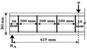 |
|
| Li et al. [18] | 32.13 | 2 | 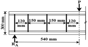 |
|
| Khalil et al. [21] | 26.4 | 1 | 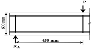 |
|
| Present study | 15.9 | 1.5 | 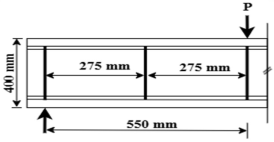  |
|
| Tensile Strength (MPa) | Diameter (μm) | Fiber Length (mm) | Young’s Modulus (GPa) | Density (g/cm3) |
|---|---|---|---|---|
| 1600 | 40 | 12 | 40 | 1.3 |
| Diameter (mm) | Yield Strength (MPa) | Young’s Modulus (GPa) |
|---|---|---|
| 6 | 464 | 200 |
| 20 | 550 | 203 |
| 25 | 550 | 203 |
| Binder | Silica Sand (kg/m3) | Water (kg/m3) | Superplasticizer (kg/m3) | PVA Fibers (kg/m3) | ||
|---|---|---|---|---|---|---|
| Cement (kg/m3) | Fly Ash (kg/m3) | Silica Fume (kg/m3) | ||||
| 257.4 | 772.2 | 257.4 | 450.45 | 347.49 | 2.57 | 26 |
| Cement (kg/m3) | M-Sand (kg/m3) | Coarse Aggregate (kg/m3) | Water (kg/m3) |
|---|---|---|---|
| 323.5 | 704 | 1320 | 146 |
| S. No. | Experimental Set | Specimen ID | Beam Dimensions (mm) | Shear Span (mm) | Number of Shear Reinforcements | ECC Layer Thickness (mm) | ||
|---|---|---|---|---|---|---|---|---|
| L | B | D | ||||||
| 1 | Set-I | CDB-100-0 | 1500 | 150 | 400 | 550 | - | - |
| 2 | CDB-100-1 | 1 | - | |||||
| 3 | CDB-100-2 | 2 | - | |||||
| 4 | SDB-100-0 | - | 20 | |||||
| 5 | SDB-100-1 | 1 | 20 | |||||
| 6 | SDB-100-2 | 2 | 20 | |||||
| 7 | Set-II | CDB-200-0 | 1500 | 150 | 400 | 500 | - | - |
| 8 | CDB-200-1 | 1 | - | |||||
| 9 | CDB-200-2 | 2 | - | |||||
| 10 | SDB-200-0 | - | 20 | |||||
| 11 | SDB-200-1 | 1 | 20 | |||||
| 12 | SDB-200-2 | 2 | 20 | |||||
| Specimen ID | Ductility Index |
|---|---|
| CDB-100-0 | 1.27 |
| CDB-100-1 | 1.28 |
| CDB-100-2 | 1.30 |
| SDB-100-0 | 1.30 |
| SDB-100-1 | 1.33 |
| SDB-100-2 | 1.32 |
| CDB-200-0 | 1.32 |
| CDB-200-1 | 1.35 |
| CDB-200-2 | 1.37 |
| SDB-200-0 | 1.37 |
| SDB-200-1 | 1.46 |
| SDB-200-2 | 1.50 |
| Experimental Set | Specimen ID | Peak Load (kN) | Effective Contribution (%) | |||
|---|---|---|---|---|---|---|
| Experimental | Theoretical | VCon | VSR | VECC | ||
| Set-I | CDB-100-0 | 176 | 185 | 100 | 0 | 0 |
| CDB-100-1 | 194 | 204 | 97 | 3 | 0 | |
| CDB-100-2 | 229 | 232 | 93 | 7 | 0 | |
| SDB-100-0 | 272 | 281 | 80 | 0 | 20 | |
| SDB-100-1 | 298 | 301 | 77 | 3 | 20 | |
| SDB-100-2 | 339 | 342 | 71 | 6 | 23 | |
| Set-II | CDB-200-0 | 184 | 200 | 100 | 0 | 0 |
| CDB-200-1 | 196 | 216 | 97 | 3 | 0 | |
| CDB-200-2 | 236 | 238 | 93 | 7 | 0 | |
| SDB-200-0 | 276 | 289 | 82 | 0 | 18 | |
| SDB-200-1 | 304 | 310 | 78 | 3 | 20 | |
| SDB-200-2 | 343 | 347 | 72 | 7 | 21 | |
Disclaimer/Publisher’s Note: The statements, opinions and data contained in all publications are solely those of the individual author(s) and contributor(s) and not of MDPI and/or the editor(s). MDPI and/or the editor(s) disclaim responsibility for any injury to people or property resulting from any ideas, methods, instructions or products referred to in the content. |
© 2025 by the authors. Licensee MDPI, Basel, Switzerland. This article is an open access article distributed under the terms and conditions of the Creative Commons Attribution (CC BY) license (https://creativecommons.org/licenses/by/4.0/).
Share and Cite
Kannan, H.; Veerappan, S.K.; Sivasubramanian, M.V.R. Experimental and Numerical Investigation of Shear Performance of RC Deep Beams Strengthened with Engineered Cementitious Composites. Constr. Mater. 2025, 5, 51. https://doi.org/10.3390/constrmater5030051
Kannan H, Veerappan SK, Sivasubramanian MVR. Experimental and Numerical Investigation of Shear Performance of RC Deep Beams Strengthened with Engineered Cementitious Composites. Construction Materials. 2025; 5(3):51. https://doi.org/10.3390/constrmater5030051
Chicago/Turabian StyleKannan, Hamsavathi, Sathish Kumar Veerappan, and Madappa V. R. Sivasubramanian. 2025. "Experimental and Numerical Investigation of Shear Performance of RC Deep Beams Strengthened with Engineered Cementitious Composites" Construction Materials 5, no. 3: 51. https://doi.org/10.3390/constrmater5030051
APA StyleKannan, H., Veerappan, S. K., & Sivasubramanian, M. V. R. (2025). Experimental and Numerical Investigation of Shear Performance of RC Deep Beams Strengthened with Engineered Cementitious Composites. Construction Materials, 5(3), 51. https://doi.org/10.3390/constrmater5030051