1. Introduction and Background
The simple for dead load and continuous for live load (SDCL) steel bridge system has been studied extensively in the past few years [
1,
2,
3,
4,
5]. In this system, the steel girders are placed simply supported and are made continuous for live loads by casting a concrete diaphragm at the intermediate piers. The construction sequence differs from conventional steel bridge construction, in which the girders are erected continuously over multiple spans, then the deck is cast on site. The construction method used in the SDCL steel bridge system results in a reduced negative moment at the intermediate piers, leading to an economical girder design for multi-span steel bridge systems [
5].
In an SDCL steel bridge system, the girders can maintain a constant section throughout their span length. The ability of the girders to have a constant section throughout the span length eliminates the requirement for splices at inflection points. Further, the ends of the girders are encased in the concrete diaphragm, which eliminates expensive joint detailing and protects the end of the girder from corrosion due to leakage at these joints. Therefore, an SDCL steel bridge system improves the durability and service life of steel bridges.
The performance of the SDCL steel bridge system using a cast-in-place diaphragm for non-seismic application has been extensively investigated, and the system has been implemented in non-seismic areas of the U.S. The seismic application of the system has also been investigated through numerical modeling [
4], experimental component testing [
5], and shake-table testing [
6]. A connection detail has been developed for SDCL in seismic areas, and proof-of-concept testing using component- and system-level experiments has been performed on this connection detail. In these studies, the connection detail for the SDCL steel bridge system employs a diaphragm constructed using cast-in-place normal strength concrete (NSC). However, the application of ultra-high-performance concrete (UHPC) for accelerated bridge construction (ABC) is becoming popular due to the superior characteristics of the material [
7,
8]. Using UHPC in the diaphragm region of an SDCL steel bridge and encasing the girder-ends will simplify the connection detail and improve the service life and durability of the structure. This study aims to further simplify the connection detail for ABC applications of SDCL steel bridge system in seismic areas using UHPC.
UHPC has higher compressive and tensile strength than normal strength concrete (NSC). Furthermore, the development length for reinforcing steel bars in UHPC is much shorter than NSC, which makes it suitable for ABC applications [
9]. The dense microstructure of UHPC also contributes to its enhanced durability [
10]. UHPC has received significant attention in the United States over recent years, particularly for constructing new bridge elements [
11,
12,
13,
14,
15,
16,
17,
18,
19,
20]. Several research endeavors have focused on utilizing UHPC as a retrofit material for reinforced beams, columns, and beam–column joints, highlighting its versatility and performance benefits [
21,
22,
23,
24,
25,
26,
27,
28,
29]. Additionally, advanced non-corrosive materials such as GFRP bars have been studied in bridge engineering, demonstrating the improved flexural behavior and durability of concrete elements under various loading conditions [
30,
31,
32].
In an SDCL steel bridge constructed in seismic areas, the superstructure becomes integral to the substructure. The design philosophy of bridges in seismic areas for integral bridges is to have predefined locations for damage, i.e., plastic hinges in the column, to prevent inelasticity in the capacity-protected elements, i.e., superstructure. The connection elements of the SDCL steel bridge system are capacity protected and should remain elastic under earthquake excitation.
This study investigated the application of UHPC as a diaphragm material for non-seismic and seismic applications through numerical analysis. The non-seismic application of the UHPC connection is summarized herein, but readers are referred elsewhere for a complete description and the development of the connection detail [
33,
34]. This paper presents the numerical investigation to develop the UHPC connection detail for SDCL steel bridges in seismic areas.
1.1. Non-Seismic Application
This section provides a summary of the connection details that were developed for the non-seismic applications of the SDCL system. The connection detail developed using NSC is schematically shown in
Figure 1a. This detail has been developed at the University of Nebraska Lincoln through numerical and experimental analysis. This connection detail consists of a cast-in-place diaphragm with the width of the pier encasing the end of the girders. The live load continuity reinforcement is developed using a 90° hook inside the cast-in-place diaphragm. For the end detail of the girder, an end-plate is used. In addition, a steel block is welded to the end of the bottom flange. The steel blocks from the two girders from each span should be in contact to transfer the compression forces without crushing the concrete in the diaphragm. For non-seismic detail, the NSC diaphragm should be reinforced. This detail has been implemented in non-seismic areas and has shown satisfactory performance.
As mentioned before, the research study on using UHPC in the SDCL steel bridge system resulted in a connection detail suitable for non-seismic areas as a basis for the current study. The connection detail was developed through a numerical study and is schematically shown in
Figure 1b,c. The components of this connection are essentially similar to the NSC detail, but owing to the superior properties of UHPC, the detail for non-seismic applications is simplified. For this detail, the diaphragm will be partially precast with NSC, and the remaining parts will be cast in place with UHPC. The live load continuity reinforcement is developed in the UHPC using straight detail with a shorter development length, eliminating the need for a 90° hook in the NSC diaphragm. The girder-end detail is simplified, and no end-plates are required. Also, the steel blocks at the bottom flanges are eliminated. The girders must be seated at a height and with a gap at the end of them so that the UHPC is cast under the girder and between the two girders that are made continuously to ensure the full development of the compression strut within the UHPC. One of the main differences is that the cast-in-place portion of the UHPC does not require additional reinforcement.
Using UHPC in the diaphragm in non-seismic applications results in many advantages and improvements to the connection detail. Other than the simple detail of the girder-ends and the deck reinforcement developed in the diaphragm, the gap between the girders increases the tolerances of the construction. Eliminating the reinforcement for the UHPC portion of the diaphragm reduces the on-site construction times. Furthermore, the end of the girders will be protected against corrosion in harsh environments when encased with UHPC.
1.2. Seismic Application
The seismic application of the SDCL system has been investigated at the Florida International University through numerical analysis [
3]. The developed connection detail has been through proof-of-concept component-level and system-level testing [
5]. It was concluded from these studies that by using such detail in an SDCL steel bridge system, the damage induced from the earthquake excitation will be confined to the desired and predefined locations in the structure (Plastic hinges). The resulting connection detail from these studies is shown in
Figure 2a. In this connection, the NSC diaphragm is cast in place with the full width of the dropped cap to accommodate all the required reinforcement, including the joint shear reinforcement and fully developing the column bars to the deck level. The live load continuity reinforcement is developed using a
hook inside the cast-in-place diaphragm. Similar to non-seismic detail, the girder-end detail includes an end-plate and a steel block at the bottom flange. The tie bars between the bottom flanges of the adjacent girders are required to transfer the possible tensile forces that may occur under vertical excitations. Shear connectors are provided at the bottom flanges to ensure the force transfer. Vertical dowel reinforcement is required in the cap beam. These bars are also part of the joint shear reinforcement to make the diaphragm integral to the drop cap.
The main objective of this study is the connection detail for the SDCL steel bridge system using UHPC for the seismic areas. The connection detail was developed using numerical analysis explained hereinafter. The envisioned connection detail using UHPC for the seismic areas is shown in
Figure 2b,c. The components of this connection are as follows:
The diaphragm is partially precast with the dropped cap, and the remaining portion is cast in place with UHPC. The combined section of UHPC and NSC should accommodate all the required reinforcement, including the joint shear reinforcement and the development of column longitudinal reinforcement. The pull-out capacity of the connection under vertical excitation loading defines the width of the UHPC.
Live load continuity reinforcement is developed in the UHPC using straight bar detail with a shorter development length similar to the non-seismic detail.
The girder-end detail is designed to be simple, without the need for end-plates or steel blocks, similar to the detail for non-seismic applications. However, a mechanical connection should be provided between the bottom flange and the UHPC to prevent the pull-out of the girder under vertical excitations.
The UHPC portion should accommodate the essential reinforcement detailing required for the seismic design. However, reinforcement placement through the girder webs is not required.
2. Research Approach
The research methodology in this study was similar to the development of the non-seismic detail [
34]. The validated numerical models developed previously were used to analyze the connection requirement for seismic areas. First, a full-scale prototype bridge was designed for a high seismic location using the AASHTO LRFD [
35], considering the SDCL assumptions. Then, the connection over the middle pier was designed according to the findings for the non-seismic applications.
Considering that the bridge will undergo earthquake excitations other than the gravity-type loadings, three loading cases were considered to cover the various conditions the bridge might experience. The effect of gravity-type loadings resulting from live loads was considered using a push-down loading case where the connection undergoes negative moments. The effect of earthquake excitation was considered in two different loading cases: the push-up loading to simulate the vertical excitation and moment reversal loading, which simulates the horizontal component of the excitation along the bridge length.
A set of parameters, such as the width of the diaphragm and the length of the UHPC portion of the diaphragm, was considered, and the effect of these parameters was quantified. At the conclusion of the parametric study, recommendations were developed for designing the connection detail for an SDCL steel bridge system using the UHPC diaphragm.
3. Modeling Assumptions and Definitions
The validation and development of the numerical assumptions were performed as part of the study on the non-seismic application, and this section provides a short description of the material models, element types, and contact types used in the numerical analysis. Readers are referred elsewhere for a complete description of the modeling assumptions and definition [
33,
34]. The numerical analysis was performed using the Ansys finite element package [
36]. The Newton–Raphson method was employed to solve the non-linear equations in these models, as implemented in ANSYS.
3.1. Steel Reinforcement
The experiments used for validating the numerical analysis techniques utilized Grade 60 ASTM A706 steel reinforcement, commonly used in the U.S. Bilinear isotropic hardening material model, with the properties defined in
Table 1, was used for modeling the steel reinforcement. The element type used for modeling the reinforcement was REINF264, defined based on a 3D base element with uniaxial properties.
3.2. Steel Girders
Similar material models to the reinforcement were used for the steel girders. However, Grade 50 ASTM A709 was assumed for the material. The defined material properties of the isotropic hardening material are presented in
Table 1. Elements with 3D geometry and shell formulation (SLOSH190) were used to model the webs and flanges of the steel girders. The use of solid-shell elements provides the opportunity to define different contact types between concrete and steel, especially in the case of the SDCL steel bridge system, where the steel girders are embedded inside the concrete.
3.3. Normal Strength Concrete
NSC was modeled using the coupled damage–plasticity microplane model developed by Zreid and Kaliske [
37,
38,
39]. The material parameters used in this study were taken from the literature and are presented in
Table 2. An eight-node 3D element type (CPT215) compatible with the material model was used for modeling the NSC. The compressive strength
used in the models of this study was assumed to be 35 MPa.
3.4. Ultra-High-Performance Concrete
The coupled damage–plasticity microplane model was used for the UHPC material, similar to the NSC. However, the current literature has not adopted the material model for UHPC. The material parameters used for UHPC were calibrated using a set of experimental data from the literature [
7,
40,
41] through an iterative process. It was intended that the material response in these models match the response from the experiments. The final material definitions used are presented in
Table 2.
3.5. Steel and Concrete Connection
The interaction of the steel plates and concrete materials (NSC and UHPC) was defined using contact (CONTA174) and target (TARGE170) elements. The models used two different contact definitions: a bonded contact for steel surfaces connected to adjacent concrete using a mechanical connection such as shear connectors and a frictional contact with a lower bound friction coefficient for surfaces without any mechanical connection. The bonded contact prevents the sliding and opening of the two surfaces. The frictional contact allows for a localized separation between steel plates and concrete when under tension.
3.6. Validating Numerical Models
A series of analyses were conducted to determine the validity of the models using the assumptions and material models discussed above. The validation process employed different experimental results from the non-seismic SDCL connection development stages using NSC and a large-scale UHPC experiment. The results from the developed model using the described assumptions were compared with the experimental results in terms of both local and global responses. Mesh sizes ranging from 50 mm (1.97 in) to 100 mm (3.94 in) were examined to investigate the mesh sensitivity of the material model. The impact of mesh size on the load–displacement curve was negligible, attributed to the mesh-insensitive concrete material models used. Thus, the current study utilized a 100 mm (3.94 in) mesh size across all models to reduce computational cost.
4. Design of the Full-Scale Bridge
A prototype bridge featuring plate girders from an FHWA design example [
42] was selected and redesigned for regions with high seismic activity. The selected bridge comprised two spans, each measuring 30.5 m (100 ft). The design process utilized hand calculations and LEAP Bridge Concrete V20 software [
43], with the assumptions of the SDCL steel bridge system. The complete design procedure for the selected bridge is presented elsewhere for the readers’ reference [
33].
The design of the superstructure for positive and negative sections was based on AASHTO guidelines, similar to the approach in the FHWA design example [
42]. Dead loads on the structures (DC1, DC2, DW) were determined at 10 ft intervals using a spreadsheet. The LEAP Bridge Steel software was used to calculate the live load, assuming continuous girders, and applying AASHTO LRFD specifications for lane, tandem, and truck loadings. The positive and negative sections of a girder with its associated tributary deck were evaluated under factored loads based on specified load cases from AASHTO LRFD [
35].
The design process for the column and cap beam was carried out in two steps. The first step involved designing the drop cap using the LEAP Bridge Steel software, assuming simply supported spans and considering only dead loads. This design approach led to a drop-cap section measuring 0.61 m (2 ft) in height and 1.83 m (6 ft) in width. In the second step, the full cap beam and its connection were designed assuming an NSC diaphragm using LEAP Bridge Concrete.
The connection was detailed based on the findings of the previous studies and the developed guidelines [
44]. The components of the SDCL seismic connection using NSC include steel blocks, tie bars, deck reinforcement, and dowel bars. The dowel bars were designed based on the cap beam joint shear design guidelines from AASHTO LRFD and Caltrans SDC [
35,
45]. These elements were designed as a basis for comparison and a starting point for developing the UHPC connection.
5. Model Description
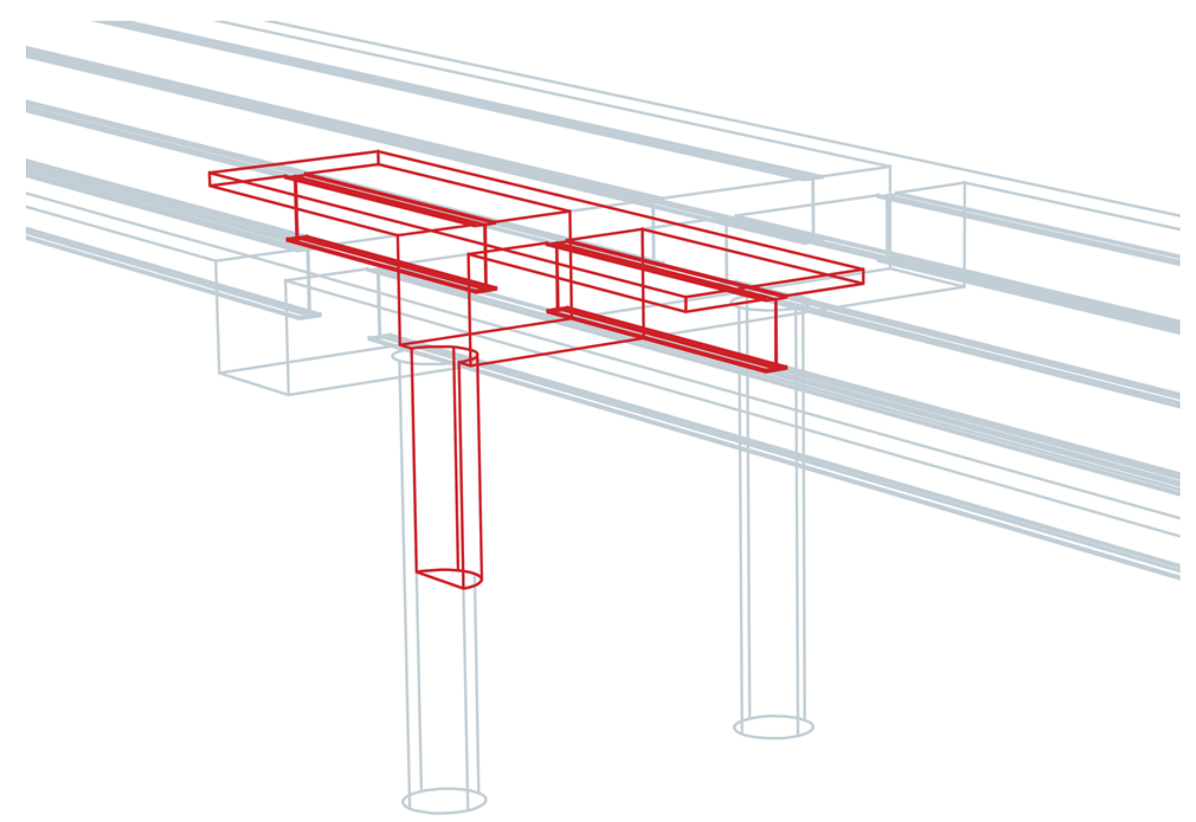
As shown in
Figure 3, only a portion of the cap consisting of one girder and half a column of the four girders and two columns were modeled to simplify the models and reduce the numerical intensity. The model incorporated two symmetry planes at the points where the cap beam and decks ended. The length of the superstructure was different for different loading cases. In all cases, detailed modeling was limited to a segment of the girder and deck, extending from the pier to the first designated cross-frame. Modeling the remaining part of the superstructure between the cross-frame and the inflection point was achieved using line elements and remote displacements.
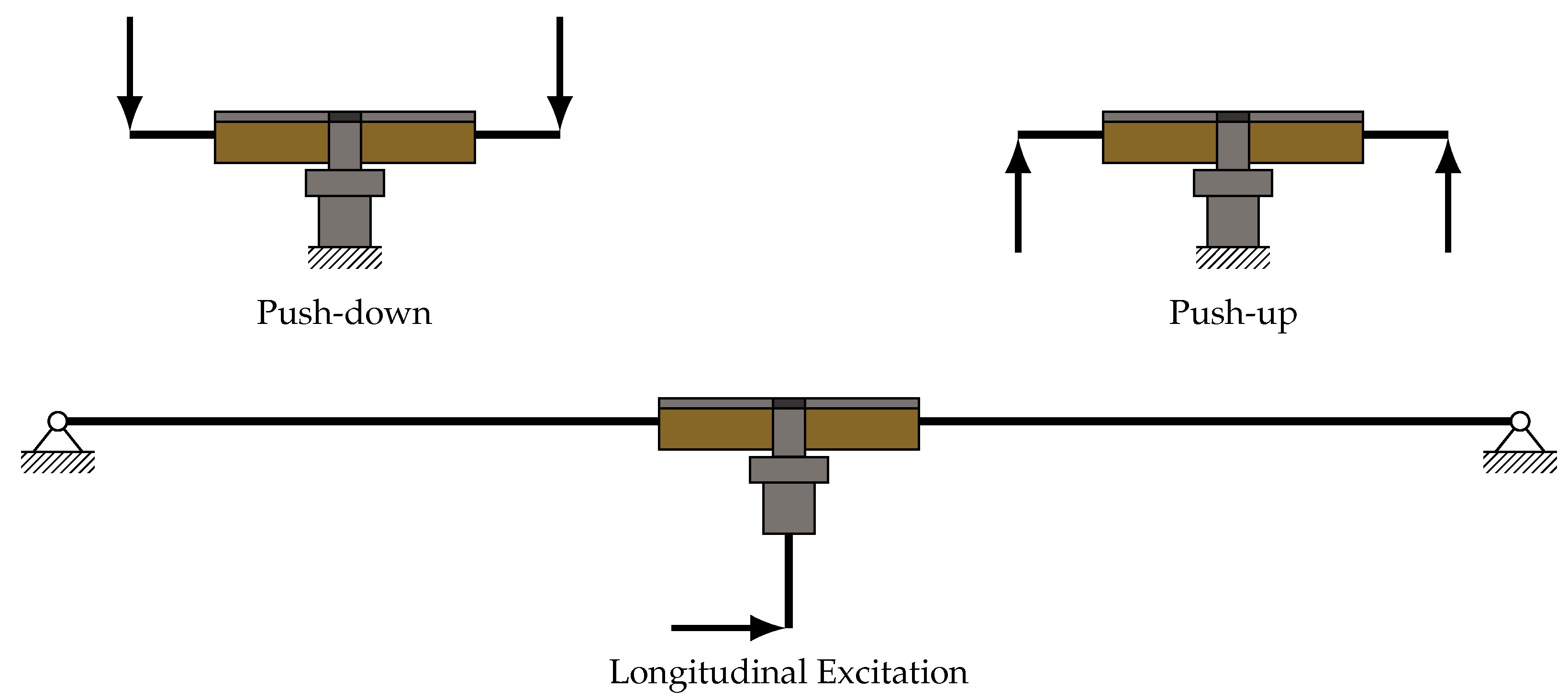
The purpose of the full-scale models was to investigate the performance of a bridge system featuring the developed SDCL connection detail under different loading conditions. Bridge loads in seismic zones typically fall into three categories: gravity-type loadings, vertical excitation, and longitudinal excitation. These loading cases are shown in
Figure 4.
Gravity-type loadings, including dead loads, live loads, etc., act downward on the spans, resulting in negative moments at the pier location. The superstructure length on each side of the pier was determined based on the inflection point under gravity-type loadings. This choice was made for the continuous superstructure to ensure that the numerical models accurately reflect the moment and shear demand. Given that the column experiences pure axial loading under gravity-type loadings, its length does not affect the results. Displacement-controlled downward loading was applied at the inflection points at both ends of the superstructure.
The models utilized the same geometric and modeling assumptions for the analysis under vertical excitations as those for gravity-type loadings. The bridge experiences vertical acceleration when subjected to vertical earthquake excitation. Upward acceleration leads to gravity-type loadings, while downward acceleration induces a positive moment at the middle pier location. Therefore, the same bridge length was selected on both sides of the pier, similar to the gravity-type loading models. Vertical displacement-controlled loading was applied at the inflection points of the superstructure as shown in
Figure 4. In this loading case, the superimposed dead and live loads were conservatively excluded, producing a more critical condition. It should be noted that the negative moment, due to the upward acceleration, was not modeled separately, and the demand loads were compared with the combinations from the gravity-type loadings.
Under longitudinal excitation, the inflection points in the superstructure form at the abutment for a two-span bridge with simply supported abutments. The formation of these inflection points at the abutment necessitates the modeling of the entire length of the bridge. Given that the columns are fixed to the footing, they exhibit a double curvature deformation when subjected to horizontal excitations. The model incorporated only half the length of the columns extending from the inflection point to the cap beam. The superstructure ends were assumed to be simply supported in this modeling approach, and displacement-controlled loading was applied to the column end.
6. Parametric Study
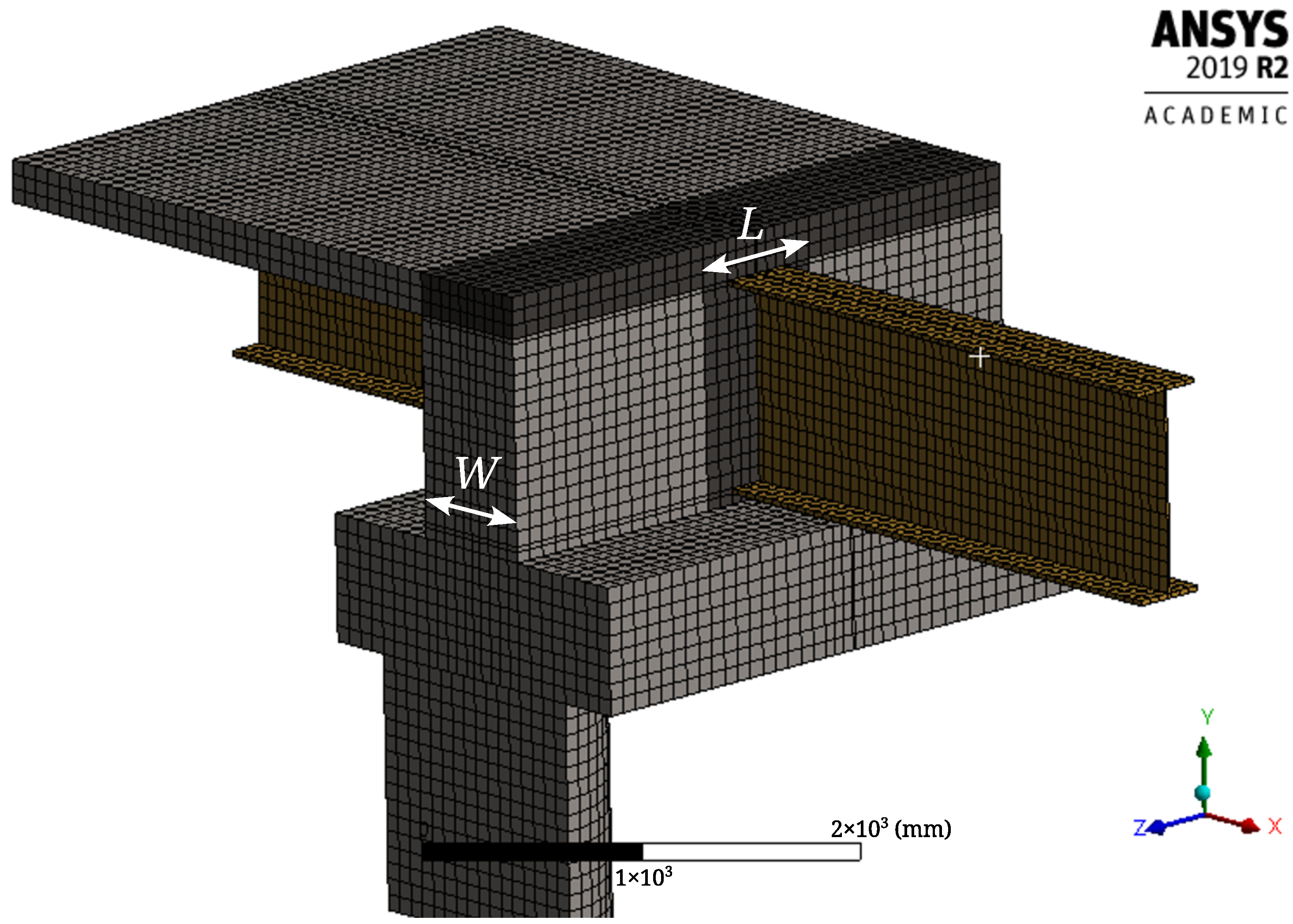
The basis for studying the effect of different parameters for the seismic applications of the SDCL steel bridge system was the connection designed minimally for non-seismic application as detailed in the previous study on the non-seismic detail. The non-seismic application of the UHPC connection for the SDCL steel bridge system requires a simple girder-end detail, a minimum gap width between the adjacent girders, and a minimum seat height for the girder so that UHPC is cast below the bottom flange of the girder as well. Therefore, the parameters chosen for this study were the required width and length of the UHPC as schematically shown in
Figure 5. The presence of the end-plate as a mechanical connector was also investigated as a parameter to account for the potential sliding of the girder out of the UHPC during push-up and longitudinal excitation loading cases. For cases without the end-plate, the bottom flange could be connected to the UHPC using shear connectors, for which, in this study, a bonded behavior was considered. For cases with the end-plate, as the end-plate introduces an inherent crack in the UHPC, the connection of the back of the end-plate to the UHPC was studied by similar bonded contact for two models. The parameters investigated and the list of models are listed in
Table 3.
As the connection was designed for non-seismic application under push-down types of loading, the main loading case studied in this section was the push-up loading case. The moment reversal case was also investigated. However, only one of the models was included in the list. Under this type of loading, the behavior remains unaffected by the currently selected parameters as detailed in subsequent sections.
In the loading column of
Table 3, D corresponds to push-down loading (gravity-type loading), U to push-up loading (vertical component of earthquake excitation), and R to reversal loading (longitudinal component of earthquake excitation). Additionally, in the table columns,
W refers to the width of the diaphragm,
L to the length of the UHPC diaphragm along the cap beam length, and E or NE in the model names to the presence or absence of the end-plate at the end of the girder. For contact type B, bonded contact is applied between the bottom flange and UHPC for models without the end-plate and between the back of the end-plate and UHPC for models with the end-plate. For contact type F, all the steel surfaces at the end of the girder have frictional contact with UHPC.
7. Results and Discussion
In most developed numerical models, global load-deflection responses, failure mode, and damage progression in various elements were investigated. During the design process, numerical results of the gravity-type loading and vertical excitation were compared with the demand loads calculated for service, strength, and extreme limit states. As the capacity design approach was used for the columns, the results of the horizontal excitation models were investigated for damage formation at extreme displacement levels applied to the column.
7.1. Gravity-Type Loading
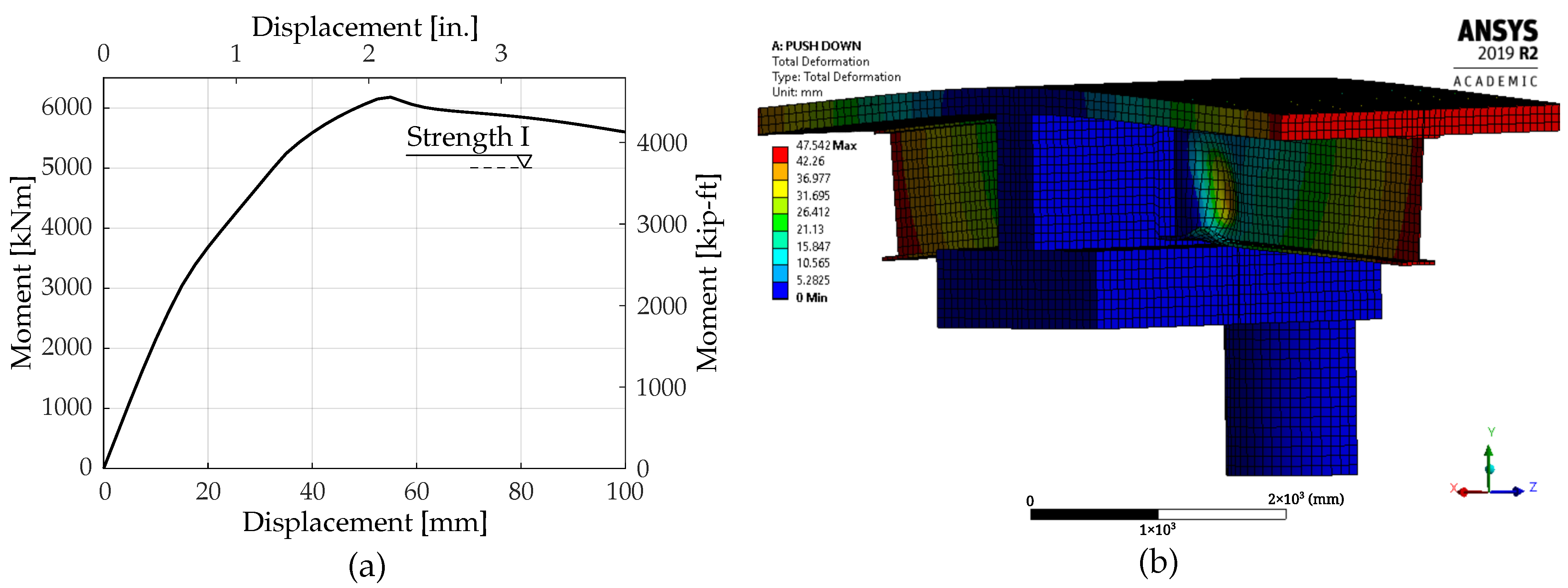
In the first iteration (D-W16-L18-NE-F), the minimum required UHPC was utilized, similar to its application in non-seismic areas. In this case, with a bottom flange thickness of 25.4 mm (1 in), a 101.6 mm (4 in) gap was selected. The design incorporated a 50.8 mm (2 in) seat height for the steel girder. The UHPC diaphragm was designed with dimensions of 406.4 mm (16 in) in width (accounting for a 6 in embedment per girder) and 457.2 mm (18 in) in length (including a 2 in side gap). As anticipated, the behavior of the model under the push-down loading was desirable, and failure occurred due to the local buckling of the girders outside the diaphragm (
Figure 6b). The capacity of the connection also exceeded the moment capacity of the section.
Figure 6a shows the moment–displacement response of the first model (D-W16-L18-NE-F) and the maximum load combination (strength I limit state).
7.2. Vertical Excitation
AASHTO LRFD does not provide a clear definition of the demand load required for vertical excitation [
35]. However, according to Caltrans SDC [
45], the superstructure should be designed to withstand an upward force of 25% of the dead loads, reflecting the vertical excitation in high seismic areas (peak ground acceleration of higher than 0.6 g). Caltrans specifies that this loading should not be combined with the superstructure dead load. For the case of the continuous girders under dead and live loads, the middle pier experiences a negative moment due to the superstructure dead load. Excluding the dead load could lead to a more substantial vertical load (125% of the dead load) when combined with existing loads. Therefore, the response was compared with this threshold in all models with a push-up loading.
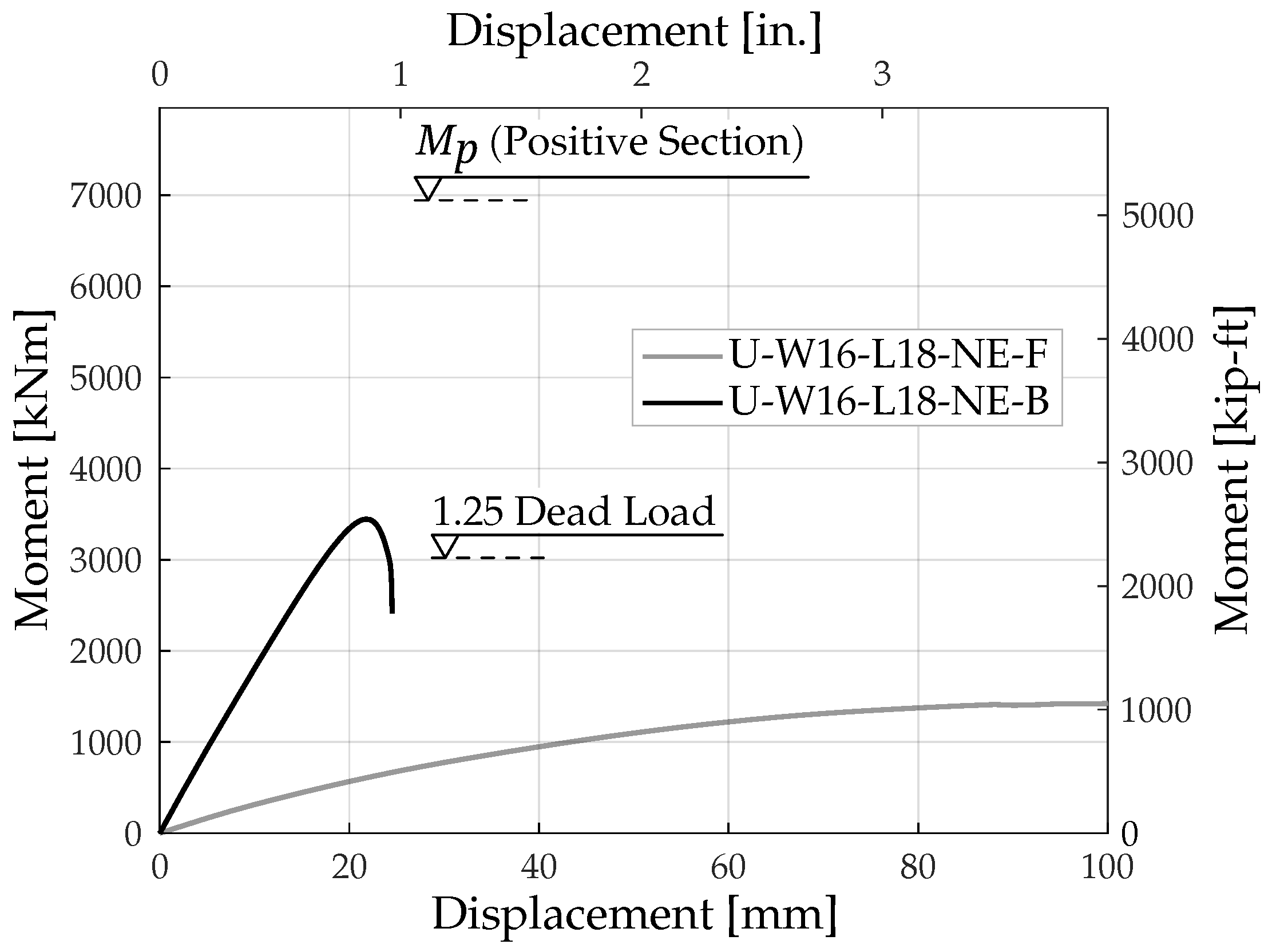
The configuration of the second model (U-W16-L18-NE -F) matched the first model but was subjected to push-up loading. Given that the contact between the steel and UHPC was frictional, the steel experienced slippage from the UHPC, leading to a significantly reduced system capacity and stiffness.
Figure 7 shows the comparison of moment–displacement responses of this model and its companion model (U-W16-L18-NE-B), where the top surface of the bottom flange is bonded to the UHPC. Mechanical connections, such as shear connectors on the steel plates, can be used to establish the bond between steel and UHPC. Providing a bonded connection between the steel flange and UHPC improves the behavior and capacity of the connection under push-up loading.
Figure 7 also shows the positive moment capacity of the superstructure and demand for the vertical excitation loading.
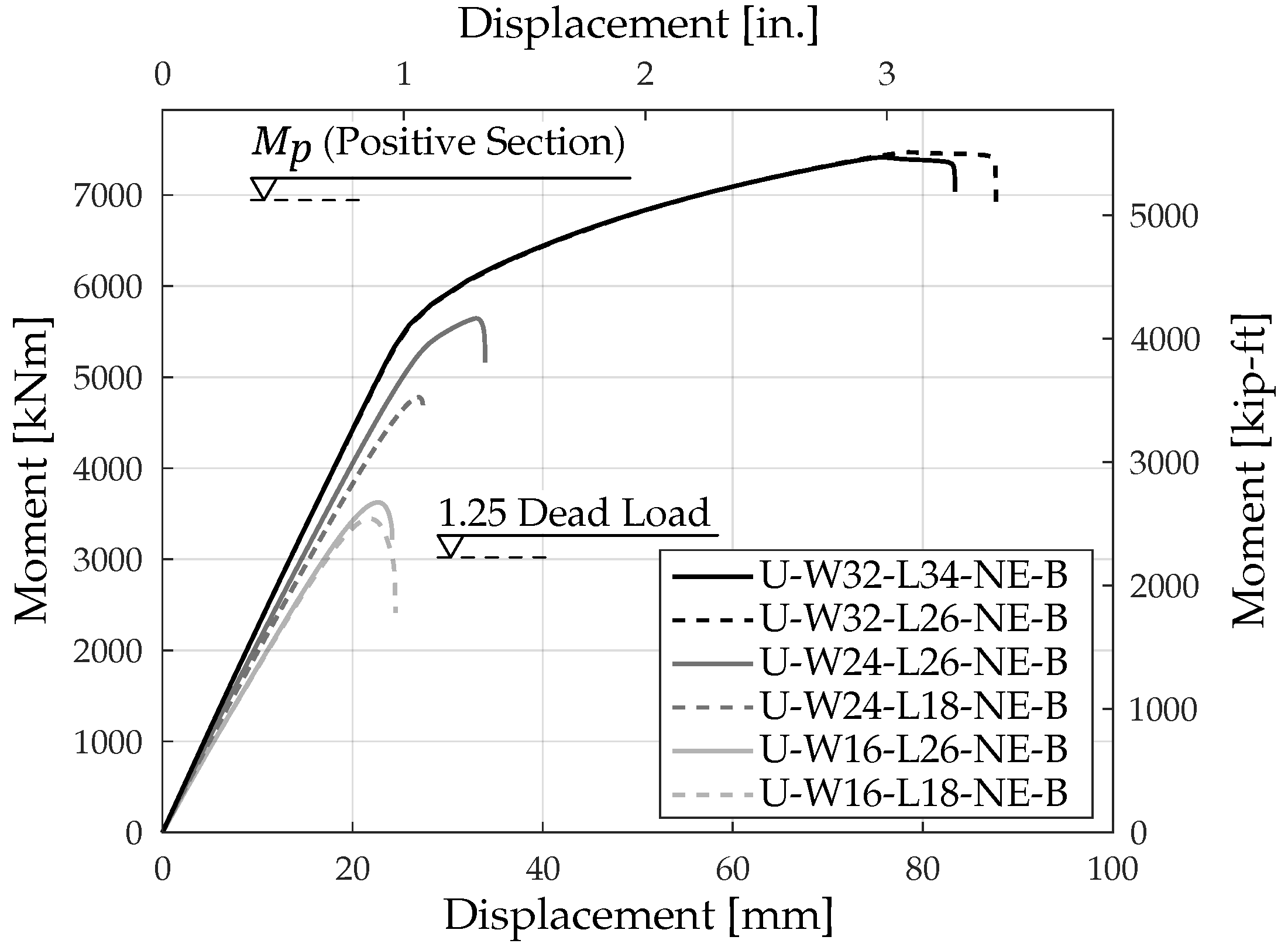
Subsequent models were developed with varying widths and lengths for the UHPC diaphragm.
Figure 8 compares the moment–displacement response of the connection for similar cases with different widths. As seen in this figure, a wider diaphragm corresponds to higher capacity. For a sufficiently wide diaphragm as seen in model U-W32-L26-NE-B, the steel yields before connection failure, resulting in a ductile behavior. The ductility in the moment–displacement response is mainly due to the yielding of the steel girder.
Figure 8 also compares the behavior of the connection under push-up loading for various lengths of the UHPC diaphragm. Despite slight variations in the connection capacity across different cases, its behavior was predominantly similar. Thus, the length of the UHPC diaphragm has minimal impact on the behavior of the connection under push-up loading.
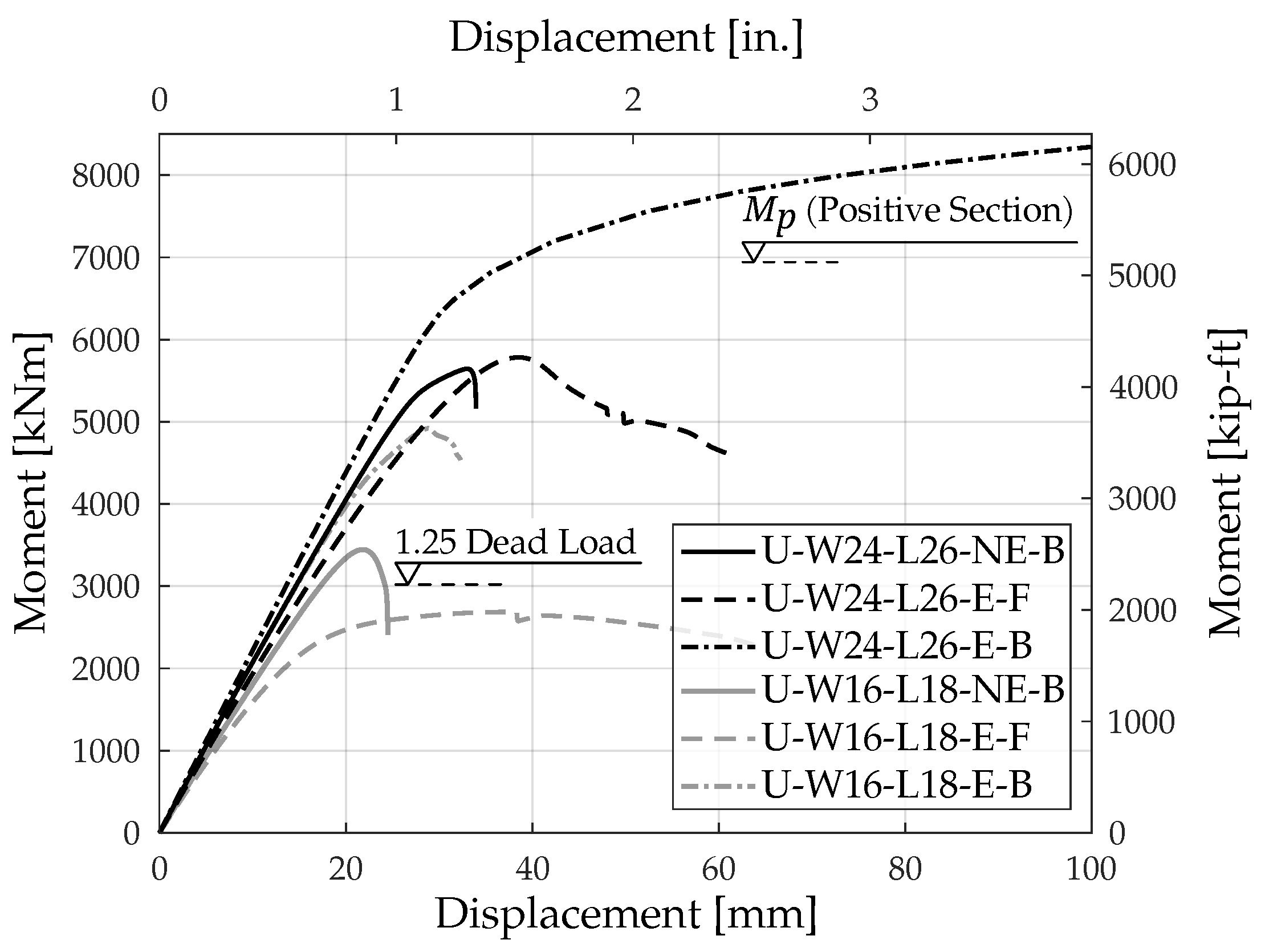
Two specific models, U-W16-L18-E-F and U-W24-L26-E-F, were developed to investigate the effect of the end-plate. The distinctive feature of these models was the addition of a 25.4 mm (1 in) thick steel plate to the end of the girder. Since the end-plate serves as a mechanical connector, the bonded connection between the bottom flange and the UHPC was not considered. The comparison of moment–displacement responses of these models with those lacking an end-plate is shown in
Figure 9. The figure shows that the capacity of the connection remains unaffected by the presence of the end-plate. In the models without the end-plate, the connection fails after the initial UHPC cracking, as the girder starts to pull out from the UHPC. In the model with the end-plate, the UHPC in the higher elevations starts to contribute, following the emergence of cracks in the lower parts (close to the bottom flange). While this contribution does not increase the capacity of the connection, it leads to a more ductile failure mode.
The presence of the end-plate introduces a discontinuity in the UHPC, which might compromise the capacity of the connection. Tension (or positive moment) can cause the gap between the steel end-plate and the UHPC to widen, simulating an inherent crack. Models with an end-plate show a decrease in cracking load, resulting in reduced stiffness when subjected to higher loads. Using mechanical connectors can prevent separation between the end-plate and the UHPC while keeping fabrication costs relatively unchanged. The addition of the shear connectors was studied in two models (U-W16-L18-E-F and U-W24-L26-E-F) to address the inherent crack problem. In these models, the back of the end-plate was assumed to be bonded with the UHPC. The moment–displacement results of these two models are also presented in
Figure 9. By incorporating a bonded connection between the end-plate and the UHPC, both the capacity and stiffness of the connection are enhanced as can be observed in the results.
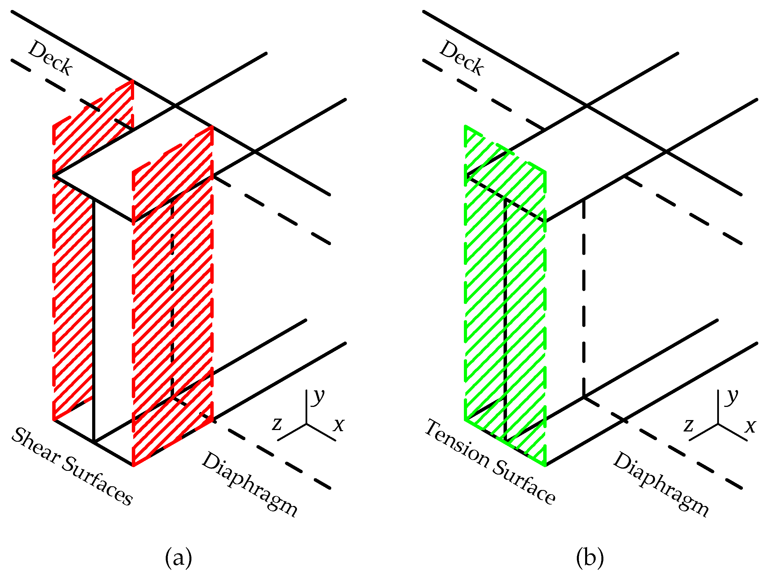
Under push-up loading, the failure in the connection starts by cracking in the UHPC near the bottom flange, accompanied by shear failure on the sides of the bottom flange. That is the main reason the capacity of the connection is not affected by the length of the UHPC. For a conservative estimate of the connection capacity under push-up loading, three failure surfaces, as illustrated in
Figure 10, can be assumed to simplify the failure mechanisms. As explained before, tension and shear cracking near the bottom flange initiate the failure in the connection. While the onset of cracking near the bottom flange indicates the beginning of failure, it does not necessarily correspond to a reduction in capacity. However, using it as a benchmark provides a conservative estimate of the connection capacity. Designing for cracking will ensure the connection remains uncracked under an earthquake excitation. The connection capacity can be derived from the combined cracking forces of three surfaces: two shear surfaces, which are cracking due to the torsion in the plane, and a tension surface, which is cracking due to the moment.
The cracking capacity of the connection under push-up loading can be calculated using the equation below:
where
is the cracking moment under positive bending,
is the polar moment of inertia of the shear surface (
Figure 10a),
is the distance from the center to the corner of the shear surface,
is the section modulus of the tension surface (
Figure 10b),
is the tensile cracking stress of the UHPC, and
is the shear cracking stress of UHPC. The shear cracking stress of the UHPC at the critical surface (shear surface in
Figure 10a) can be calculated by assuming that the cracking will occur perpendicular to the maximum principal stress. This angle is similar to the push-out or pull-out angle defined by ACI 318 [
46], equal to 1:1.5 or about
. Thus, it can be derived that
. It should be noted that this equation corresponds to the onset of cracking and not the failure. Also, for cases with an end-plate, the second term can be disregarded since there is a discontinuity in the UHPC at the location of the end-plate.
The cracking moments calculated using the above equation for the push-up models in this study are presented in
Table 4 and compared with the cracking moments obtained from the models. The moment values corresponding to a tensile stress of 8.5 MPa were interpolated to determine the cracking moments from the models. The tensile cracking stress of UHPC for the prediction of the connection cracking capacity in the above equation was also considered to be 1.24 ksi (8.5 MPa). It can be seen that the abovementioned equation offers a conservative prediction of the connection cracking capacity under push-up loading, making it suitable for design considerations.
7.3. Horizontal Excitation
The capacity of the column dictates the demand load on both the connection and cap beam, which are the investigated elements of this study. The push-over analysis performed herein ensures the formation of the damage in the column, therefore inducing the demand loads on the connection and cap beam. So, only the damage formation in different elements was studied for the moment reversal case. It is desired that under high levels of displacement, the connection and cap beam components remain elastic and undamaged.
The behavior of the models under moment reversal loading was not desirable due to the small width of the diaphragm.
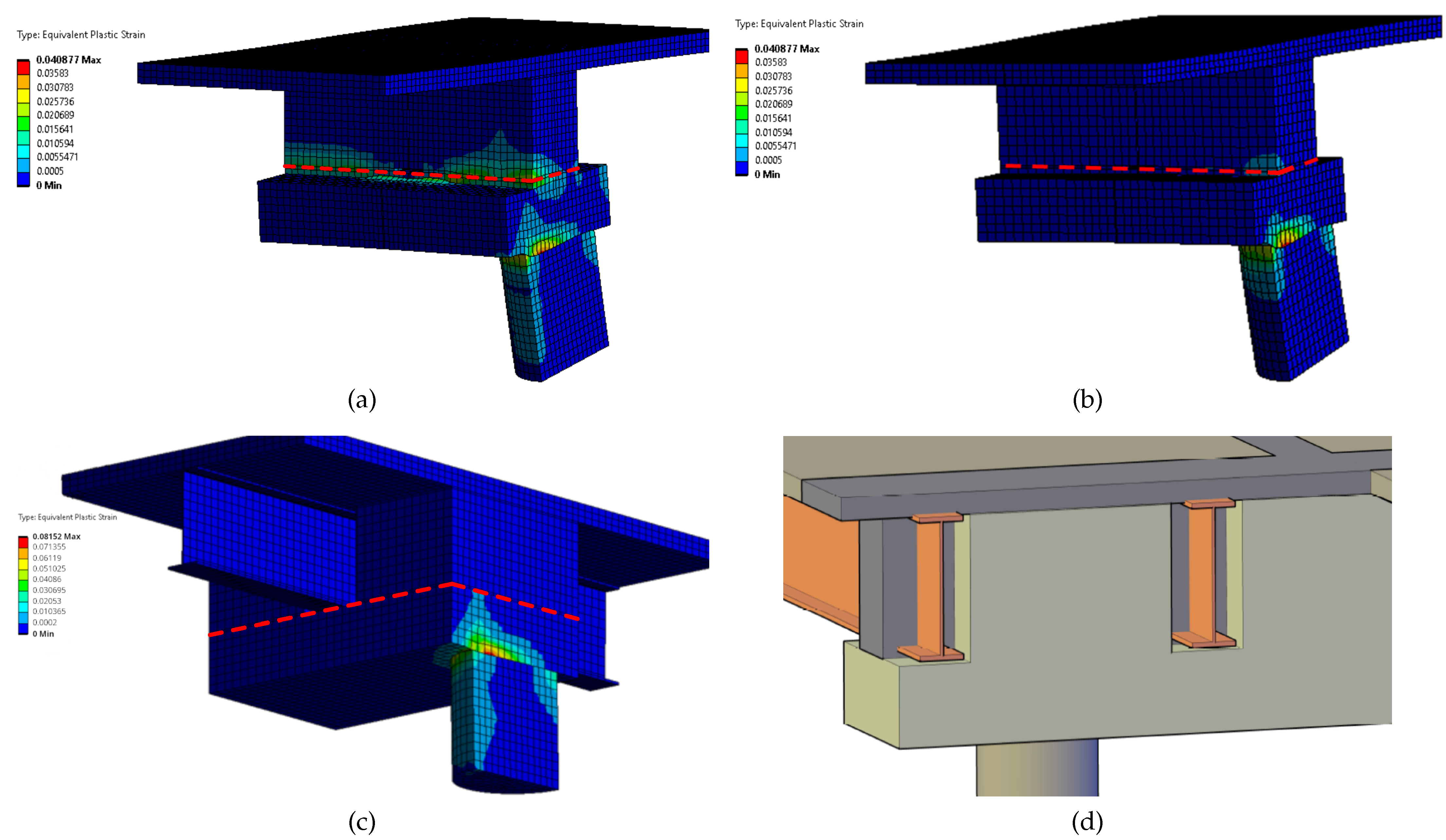
Figure 11a shows the final deformed shape and plastic strains in the model R-W32-L34-NE-B, highlighting non-linearity in the diaphragm at the section under the girder. Two main factors contribute to this non-linearity: first, the reduced depth of this section (width of the diaphragm) leads to a decreased moment of inertia, and second, some of the column longitudinal bars terminate at the top of the drop cap.
In seismic areas, this behavior is uncommon for integral cap beams because the column longitudinal bars extend to the deck level within the cap beam. Also, around the column and throughout the depth of the cap beam, additional joint vertical reinforcement (equal to 10% of the column longitudinal bars area) should be provided. This issue primarily pertains to detailing, and replacing a portion of the diaphragm with UHPC does not change the behavior. One solution to this behavior is to increase the width of the diaphragm, ensuring it covers all the column reinforcement (
Figure 11d) or include additional reinforcement to account for the decrease in the cross-sectional area. One should conduct a sectional analysis, such as a moment–curvature analysis, to address potential damage within this section. The critical section (red dashed lines in
Figure 11a) should remain elastic under the over-strength moment capacity of the column, considering the additional moment arm due to the drop-cap height.
Figure 11b shows the damage progress in a model with geometry identical to R-W32-L34-NE-B. However, in this model, the vertical reinforcement in the diaphragm section was increased, ensuring that the critical section surpassed the overstrength capacity of the column.
Increasing the width of the NSC portion of the diaphragm can address this issue (
Figure 11d). This adjustment provides sufficient space for the column longitudinal reinforcement to extend to the deck level. Additionally, this allows for the placement of the joint shear reinforcement. When the plastic hinge forms in the column, the critical section under the girder has sufficient capacity to maintain all the elements in an elastic state. In this case, a sectional analysis should be conducted to assess the yielding capacity of the critical section (under the girders).
Figure 11c shows the damage progress in a model where the UHPC remains the same as model R-W32-L34-NE-B, but the width of the concrete diaphragm is identical to that of the drop cap. The development of the column longitudinal reinforcement to the deck level and the joint shear reinforcement are all provided in this model. It can be observed that the damage does not form at the critical section.
8. Design Recommendations
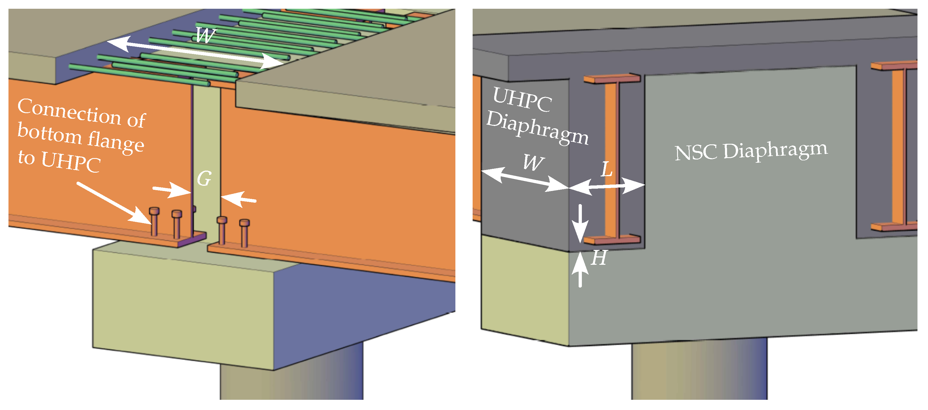
Based on the parametric study of the behavior of the connection detail, a set of recommendations has been developed for designing an SDCL steel bridge system in seismic areas utilizing UHPC. The schematic of the UHPC connection developed is shown in
Figure 12. The design considerations for the UHPC connection and each component are listed below.
All the design recommendations for connection detailing non-seismic application applies to the seismic applications. The non-seismic details include the minimum gap width between the girders of adjacent spans (G), minimum seat height for the girders (H), and minimum length of the UHPC portion of the diaphragm (L). These requirements ensure that the compression field forms mainly in the UHPC between the bottom flanges of the girders due to the gravity-type loading.
Width of the diaphragm (W): The required width of the UHPC portion of the diaphragm is defined by the development length of the deck reinforcement similar to the non-seismic detail. Additionally, it depends on the required capacity of the three failure surfaces under push-up and longitudinal loading for the seismic detail. The UHPC width could be assumed to be equal to the width of NSC for construction simplicity.
Deck reinforcement: The design of the live load continuity deck reinforcement is similar to the older connection detail. These reinforcements are designed for the negative moment demand at the pier. In the UHPC connection, the compression force would act on the bottom flange of the steel girder. The UHPC connection is developed to sustain the negative moment capacity of the girder and deck (including the continuity reinforcement).
Girder-end detail: The girder-end detail could help transfer the forces inside the diaphragm. The presence of an end-plate in the seismic connection may increase the ductility, but the inherent crack due to the presence of the end-plate reduces the cracking capacity of the connection. To further enhance the performance in the presence of an end-plate, the back of the end-plate could be mechanically connected to the UHPC using shear connectors.
The yielding capacity of the section under the girders should be checked with the overstrength capacity of the column, considering the increased moment arm. The width of the NSC portion of the diaphragm could be increased to accommodate the development of the column longitudinal reinforcement and the joint shear reinforcement in the combined cap beam and diaphragm.
9. Conclusions
This paper presents a numerical investigation of the SDCL steel bridge system to develop simplified connection details for seismic areas using UHPC. The behavior of similar connections using UHPC in non-seismic areas had been investigated and was the basis of the analysis performed in this article. The available validated numerical models were used to predict the behavior of an SDCL steel bridge system constructed using the proposed connection subjected to seismic loadings. The connection detail was refined through this process, and design recommendations were developed.
All the conclusions of the previous study and design recommendations for non-seismic areas also apply to seismic areas. The connection of girders over an intermediate pier is through a diaphragm partially cast with UHPC. The girder-end detail is simple, and no additional end-plates and steel blocks are required. Including an end-plate may increase the ductility, but it creates a discontinuity in the UHPC, potentially compromising the capacity and stiffness of the connection when subjected to higher loads. Shear connectors could be used to mechanically connect the back of the end-plate to the UHPC and prevent the separation. Moreover, a mechanical connection between the bottom flange and UHPC is required. The live load continuity reinforcement in the deck can be developed using straight bars inside the UHPC. The connection requires minimum on-site reinforcement placement, forming, and UHPC casting, making it suitable for ABC applications. Future research, including proof-of-concept experimental studies, is necessary to validate the structural performance of the proposed connection detail before its practical implementation.
Author Contributions
Conceptualization, A.A.; formal analysis, A.K. and A.S.; funding acquisition, A.A.; investigation, A.K. and A.S.; methodology, A.K., A.S. and A.A.; supervision, A.A.; visualization, A.K. and A.S.; writing—original draft, A.K. and A.S.; writing—review and editing, A.K., A.S. and A.A. All authors have read and agreed to the published version of the manuscript.
Funding
This project is supported by the US Department of Transportation through the Accelerated Bridge Construction University Transportation Center (ABC-UTC) at Florida International University (Grant Reference No.: 69A3551747121). The opinions, findings, and conclusions expressed here are those of the authors and not necessarily of the funding agency.
Data Availability Statement
The data presented in this study are available upon request from the corresponding author.
Conflicts of Interest
The author(s) declare no potential conflicts of interest with respect to the research, authorship, and/or publication of this article.
Abbreviations
The following abbreviations and symbols are used in this manuscript:
| SDCL | Simple for Dead Load and Continuous for Live Load |
| NSC | Normal Strength Concrete |
| UHPC | Ultra-High-Performance Concrete |
| ABC | Accelerated Bridge Construction |
| DC1 | Permanent load acting on the non-composite section |
| DC2 | Permanent load acting on the long-term composite section |
| DW | Wearing surface load |
| Specified compressive strength of concrete [MPa] |
| Uniaxial compressive strength of concrete [MPa] |
| Biaxial compressive strength of concrete [MPa] |
| Uniaxial tensile strength of concrete [MPa] |
| D | Push-down loading (gravity-type loading) |
| U | Push-up loading (vertical component of earthquake excitation) |
| R | Reversal loading (longitudinal component of earthquake excitation) |
| W | Width of the diaphragm |
| L | Length of the UHPC diaphragm along the cap beam length |
| E | Presence of the end-plate at the end of the girder |
| NE | Absence of the end-plate at the end of the girder |
| F | Frictional contact between all the steel surfaces at the end of the girder and UHPC |
| B | Bonded contact between the bottom flange and UHPC for models without the end-plate and between the back of the end-plate and UHPC for models with the end-plate |
| Cracking moment under positive bending [kNm] |
| Cracking moment under positive bending obtained from the models [kNm] |
| Cracking moment under positive bending using the proposed equation [kNm] |
| Polar moment of inertia of the shear surface [] |
| Distance from the center to the corner of the shear surface [mm] |
| Section modulus of the tension surface [] |
| Tensile cracking stress of UHPC [MPa] |
| Shear cracking stress of UHPC [MPa] |
References
- Farimani, M.M. Resistance Mechanism of Simple-Made-Continuous Connections in Steel Girder Bridges; The University of Nebraska-Lincoln: Lincoln, NE, USA, 2006. [Google Scholar]
- Niroumand, S.J. Resistance Mechanism of Simple-Made-Continuous Connections in Skew and Non-Skew Steel Girder Bridges Using Conventional and Accelerated Types of Construction; The University of Nebraska-Lincoln: Lincoln, NE, USA, 2009. [Google Scholar]
- Taghinezhadbilondy, R. Extending Use of Simple for Dead Load and Continuous for Live Load (SDCL) Steel Bridge System to Seismic Areas; Florida International University: Miami, FL, USA, 2016. [Google Scholar]
- Taghinezhadbilondy, R.; Yakel, A.; Azizinamini, A. Deck-pier connection detail for the simple for dead load and continuous for live load bridge system in seismic regions. Eng. Struct. 2018, 173, 76–88. [Google Scholar] [CrossRef]
- Sadeghnejad, A.; Taghinezhadbilondy, R.; Azizinamini, A. Seismic performance of a new connection detail in an SDCL steel bridge system. J. Bridge Eng. 2019, 24, 04019094. [Google Scholar] [CrossRef]
- Shoushtari, E.; Saiidi, M.S.; Itani, A.; Moustafa, M.A. Design, construction, and shake table testing of a steel girder bridge system with ABC connections. J. Bridge Eng. 2019, 24, 04019088. [Google Scholar] [CrossRef]
- Graybeal, B.A. Material Property Characterization of Ultra-High Performance Concrete; Technical Report FHWA-HRT-06-103; Federal Highway Administration, Office of Infrastructure Research and Development: Washington, DC, USA, 2006. [Google Scholar]
- Graybeal, B.A. Design and Construction of Field-Cast UHPC Connections; Technical Report FHWA-HRT-14-084; HRDI-40/10-14 (750) E; Federal Highway Administration: Washington, DC, USA, 2014. [Google Scholar]
- Graybeal, B.A.; Yuan, J. Bond Behavior of Reinforcing Steel in Ultra-High Performance Concrete; Technical Report FHWA-HRT-14-089; HRDI-40/11-14 (300) E; Federal Highway Administration: Washington, DC, USA, 2014. [Google Scholar]
- Haber, Z.B.; De la Varga, I.; Graybeal, B.A.; Nakashoji, B.; El-Helou, R. Properties and Behavior of UHPC-Class Materials; Technical Report No FHWA-HRT-18-036; Federal Highway Administration, Office of Infrastructure Research and Development: Washington, DC, USA, 2018. [Google Scholar]
- Russell, H.G.; Graybeal, B.A.; Russell, H.G. Ultra-High Performance Concrete: A State-of-the-Art Report for the Bridge Community; Technical Report No FHWA-HRT-13-060; Federal Highway Administration, Office of Infrastructure Research and Development: Washington, DC, USA, 2013. [Google Scholar]
- Graybeal, B. Ultra-high-performance concrete connections for precast concrete bridge decks. PCI J 2014, 59, 48–62. [Google Scholar] [CrossRef]
- Meng, W. Design and Performance of Cost-Effective Ultra-High Performance Concrete for Prefabricated Elements. Ph.D. Thesis, Missouri University of Science and Technology, Rolla, MO, USA, 2017. [Google Scholar]
- Azmee, N.M.; Shafiq, N. Ultra-high performance concrete: From fundamental to applications. Case Stud. Constr. Mater. 2018, 9, e00197. [Google Scholar] [CrossRef]
- Zhou, M.; Lu, W.; Song, J.; Lee, G.C. Application of ultra-high performance concrete in bridge engineering. Constr. Build. Mater. 2018, 186, 1256–1267. [Google Scholar] [CrossRef]
- Mohebbi, A.; Saiidi, M.S.; Itani, A.M. Shake table studies and analysis of a PT-UHPC bridge column with pocket connection. J. Struct. Eng. 2018, 144, 04018021. [Google Scholar] [CrossRef]
- Ren, L.; Fang, Z.; Zhong, R.; Wang, K. Experimental and numerical investigations of the seismic performance of UHPC box piers. KSCE J. Civ. Eng. 2019, 23, 597–607. [Google Scholar] [CrossRef]
- Xue, J.; Briseghella, B.; Huang, F.; Nuti, C.; Tabatabai, H.; Chen, B. Review of ultra-high performance concrete and its application in bridge engineering. Constr. Build. Mater. 2020, 260, 119844. [Google Scholar] [CrossRef]
- Wang, J.; Liu, J.; Wang, Z.; Liu, T.; Liu, J.; Zhang, J. Cost-effective UHPC for accelerated bridge construction: Material properties, structural elements, and structural applications. J. Bridge Eng. 2021, 26, 04020117. [Google Scholar] [CrossRef]
- Khodayari, A.; Mantawy, I.M.; Azizinamini, A. Experimental and Numerical Investigation of Prefabricated Concrete Barrier Systems Using Ultra-High-Performance Concrete. Transp. Res. Rec. 2023, 2677, 624–634. [Google Scholar] [CrossRef]
- Tayeh, B.A.; Bakar, B.A.; Johari, M.M.; Voo, Y.L. Utilization of ultra-high performance fibre concrete (UHPFC) for rehabilitation—A review. Procedia Eng. 2013, 54, 525–538. [Google Scholar] [CrossRef]
- Prem, P.R.; Ramachandra Murthy, A.; Ramesh, G.; Bharatkumar, B.; Iyer, N.R. Flexural behaviour of damaged RC beams strengthened with ultra high performance concrete. In Advances in Structural Engineering: Materials; Springer: New Delhi, India, 2015; Volume 3, pp. 2057–2069. [Google Scholar]
- Lampropoulos, A.; Paschalis, S.A.; Tsioulou, O.; Dritsos, S.E. Strengthening of reinforced concrete beams using ultra high performance fibre reinforced concrete (UHPFRC). Eng. Struct. 2016, 106, 370–384. [Google Scholar] [CrossRef]
- Yin, H.; Teo, W.; Shirai, K. Experimental investigation on the behaviour of reinforced concrete slabs strengthened with ultra-high performance concrete. Constr. Build. Mater. 2017, 155, 463–474. [Google Scholar] [CrossRef]
- Zmetra, K.M.; McMullen, K.F.; Zaghi, A.E.; Wille, K. Experimental study of UHPC repair for corrosion-damaged steel girder ends. J. Bridge Eng. 2017, 22, 04017037. [Google Scholar] [CrossRef]
- Murthy, A.R.; Karihaloo, B.; Priya, D.S. Flexural behavior of RC beams retrofitted with ultra-high strength concrete. Constr. Build. Mater. 2018, 175, 815–824. [Google Scholar] [CrossRef]
- Khodayari, A.; Rehmat, S.; Valikhani, A.; Azizinamini, A. Experimental Study of Reinforced Concrete T-Beam Retrofitted with Ultra-High-Performance Concrete under Cyclic and Ultimate Flexural Loading. Materials 2023, 16, 7595. [Google Scholar] [CrossRef] [PubMed]
- Li, C.; Aoude, H. Effect of UHPC jacketing on the shear and flexural behaviour of high-strength concrete beams. In Structures; Elsevier: Amsterdam, The Netherlands, 2023; Volume 51, pp. 1972–1996. [Google Scholar]
- Hoang, V.H.; Do, T.A.; Tran, A.T.; Nguyen, X.H. Flexural capacity of reinforced concrete slabs retrofitted with ultra-high-performance concrete and fiber-reinforced polymer. Innov. Infrastruct. Solut. 2024, 9, 113. [Google Scholar] [CrossRef]
- Ge, W.; Ashour, A.F.; Cao, D.; Lu, W.; Gao, P.; Yu, J.; Ji, X.; Cai, C. Experimental study on flexural behavior of ECC-concrete composite beams reinforced with FRP bars. Compos. Struct. 2019, 208, 454–465. [Google Scholar] [CrossRef]
- Al-Rubaye, M.; Manalo, A.; Alajarmeh, O.; Ferdous, W.; Lokuge, W.; Benmokrane, B.; Edoo, A. Flexural behaviour of concrete slabs reinforced with GFRP bars and hollow composite reinforcing systems. Compos. Struct. 2020, 236, 111836. [Google Scholar] [CrossRef]
- Madan, C.S.; Munuswamy, S.; Joanna, P.S.; Gurupatham, B.G.A.; Roy, K. Comparison of the flexural behavior of high-volume fly AshBased concrete slab reinforced with GFRP bars and steel bars. J. Compos. Sci. 2022, 6, 157. [Google Scholar] [CrossRef]
- Sadeghnejad, A. Alternative Connections for Accelerated Construction of Simple for Dead Load and Continuous for Live load Steel Bridge System; Florida International University: Miami, FL, USA, 2021. [Google Scholar]
- Khodayari, A.; Sadeghnejad, A.; Azizinamini, A. UHPC Connection Detail for Simple for Dead Load and Continuous for Live Load Steel Bridges in Non-Seismic Areas. J. Bridge Eng. 2023. Forthcoming. [Google Scholar]
- AASHTO LRFD Bridge Design Specifications, 8th ed.; American Association of State Highway and Transportation Officials: Washington, DC, USA, 2017.
- Ansys®. Academic Research Mechanical, Release 2019 R2; Ansys®: Canonsburg, PA, USA, 2019. [Google Scholar]
- Zreid, I.; Kaliske, M. Regularization of microplane damage models using an implicit gradient enhancement. Int. J. Solids Struct. 2014, 51, 3480–3489. [Google Scholar] [CrossRef]
- Zreid, I.; Kaliske, M. An implicit gradient formulation for microplane Drucker-Prager plasticity. Int. J. Plast. 2016, 83, 252–272. [Google Scholar] [CrossRef]
- Zreid, I.; Kaliske, M. A gradient enhanced plasticity–damage microplane model for concrete. Comput. Mech. 2018, 62, 1239–1257. [Google Scholar] [CrossRef]
- Hassan, A.; Jones, S.; Mahmud, G. Experimental test methods to determine the uniaxial tensile and compressive behaviour of ultra high performance fibre reinforced concrete (UHPFRC). Constr. Build. Mater. 2012, 37, 874–882. [Google Scholar] [CrossRef]
- Naeimi, N.; Moustafa, M.A. Compressive behavior and stress–strain relationships of confined and unconfined UHPC. Constr. Build. Mater. 2021, 272, 121844. [Google Scholar] [CrossRef]
- Barth, K.E. Steel Bridge Design Handbook Design Example 2a: Two-Span Continuous Straight Composite Steel I-Girder Bridge; Technical Report FHWA-HIF-16-002-Vol. 21; Federal Highway Administration, Office of Bridges and Structures: Washington, DC, USA, 2015. [Google Scholar]
- LEAP Bridge Concrete V20; Computer Software; Bentley Systems: Exton, PA, USA, 2020.
- Sadeghnejad, A.; Mantawy, I.; Azizinamini, A. ABC-UTC Guideline for Superstructure to Pier Connection in SDCL Steel Bridge Systems; Technical Report; Florida International University: Miami, FL, USA, 2019. [Google Scholar] [CrossRef]
- CALTRANS. Seismic Design Criteria; Version 2.0; California Department of Transportation: Sacramento, CA, USA, 2019. [Google Scholar]
- ACI Committee 318. Building Code Requirements for Structural Concrete; American Concrete Institute: Farmington Hills, MI, USA, 2014. [Google Scholar]
Figure 1.
Non-seismic connection detail for SDCL steel bridges: (a) NSC connection; (b) UHPC connection—girder-end and reinforcement detail; and (c) UHPC connection—optimized use of UHPC.
Figure 1.
Non-seismic connection detail for SDCL steel bridges: (a) NSC connection; (b) UHPC connection—girder-end and reinforcement detail; and (c) UHPC connection—optimized use of UHPC.
Figure 2.
Seismic connection detail for SDCL steel bridges: (a) NSC connection; (b) UHPC connection—girder-end and reinforcement detail; and (c) UHPC connection—optimized use of UHPC.
Figure 2.
Seismic connection detail for SDCL steel bridges: (a) NSC connection; (b) UHPC connection—girder-end and reinforcement detail; and (c) UHPC connection—optimized use of UHPC.
Figure 3.
A portion of the prototype bridge used for modeling.
Figure 3.
A portion of the prototype bridge used for modeling.
Figure 4.
Three loading cases applied to the models.
Figure 4.
Three loading cases applied to the models.
Figure 5.
Width and length of the UHPC portion of the diaphragm shown on one of the models.
Figure 5.
Width and length of the UHPC portion of the diaphragm shown on one of the models.
Figure 6.
D-W16-L18-NE-F results: (a) moment–displacement response, (b) failure mode.
Figure 6.
D-W16-L18-NE-F results: (a) moment–displacement response, (b) failure mode.
Figure 7.
Comparison of the result from models U-W16-L18-NE-F and U-W16-L18-NE-B.
Figure 7.
Comparison of the result from models U-W16-L18-NE-F and U-W16-L18-NE-B.
Figure 8.
Comparison of models under push-up loading with different widths and lengths of UHPC.
Figure 8.
Comparison of models under push-up loading with different widths and lengths of UHPC.
Figure 9.
Comparison of models with and without end-plate.
Figure 9.
Comparison of models with and without end-plate.
Figure 10.
The failure surfaces under push-up loading: (a) shear surfaces (shown in red) and (b) tension surface (shown in green).
Figure 10.
The failure surfaces under push-up loading: (a) shear surfaces (shown in red) and (b) tension surface (shown in green).
Figure 11.
Comparison of models under moment reversal loading: (a) R-W32-L34-NE-B, (b) increasing the vertical reinforcement in the same model, (c) increasing the width of the NSC diaphragm and incorporating all the vertical reinforcement, and (d) schematics of the increased width of the NSC portion.
Figure 12.
The developed connection detail for the SDCL steel bridge system utilizing UHPC for seismic areas.
Figure 12.
The developed connection detail for the SDCL steel bridge system utilizing UHPC for seismic areas.
Table 1.
Material definition of steel reinforcement and steel girders.
Table 1.
Material definition of steel reinforcement and steel girders.
| Property | Steel Reinforcement | Steel Girders |
|---|
| Modulus of elasticity [MPa] | 200,000 | 200,000 |
| Poisson ratio | 0.3 | 0.3 |
| Yield stress [MPa] | 480 | 370 |
| Tangent modulus [MPa] | 3300 | 1700 |
Table 2.
Microplane material model properties for NSC and UHPC.
Table 2.
Microplane material model properties for NSC and UHPC.
| Parameter | NSC | UHPC |
|---|
| Uniaxial compressive strength, [MPa] | | |
| Biaxial compressive strength, [MPa] | | |
| Uniaxial tensile strength, [MPa] | | |
| Intersection point abscissa between compression cap and Drucker–Prager yield function [MPa] | | |
| Ratio between the major and minor axes of the cap | 2 | 2 |
| Hardening material constant [] | 60,000 | 1 |
| Tension cap hardening constant | 1 | 20,000 |
| Tension damage thresholds | 0 | 0.003 |
| Compression damage thresholds | | 0.0002 |
| Tension damage evolution constants | 4500 | 60 |
| Compression damage evolution constants | 2000 | 500 |
| Non-local interaction range parameter [] | 100 | 50 |
| Over non-local averaging parameter | 2.5 | 1 |
Table 3.
List of models and the investigated parameters in the parametric study.
Table 3.
List of models and the investigated parameters in the parametric study.
| Name 1 | Loading | W [mm] | L [mm] | End-Plate | Contact |
|---|
| D-W16-L18-NE-F | D | 406.4 | 457.2 | No | F |
| U-W16-L18-NE-F | U | 406.4 | 457.2 | No | F |
| U-W16-L18-NE-B | U | 406.4 | 457.2 | No | B |
| U-W24-L18-NE-B | U | 609.6 | 457.2 | No | B |
| U-W16-L26-NE-B | U | 406.4 | 660.4 | No | B |
| U-W24-L26-NE-B | U | 609.6 | 660.4 | No | B |
| U-W32-L26-NE-B | U | 812.8 | 660.4 | No | B |
| U-W32-L34-NE-B | U | 812.8 | 863.6 | No | B |
| U-W16-L18-E-F | U | 406.4 | 457.2 | Yes | F |
| U-W24-L26-E-F | U | 609.6 | 660.4 | Yes | F |
| U-W16-L18-E-B | U | 406.4 | 457.2 | Yes | B |
| U-W24-L26-E-B | U | 609.6 | 660.4 | Yes | B |
| R-W32-L34-NE-B | R | 812.8 | 863.6 | No | B |
Table 4.
Comparison of the cracking moments as observed from the models and the equation.
Table 4.
Comparison of the cracking moments as observed from the models and the equation.
| Model | Mcr,M [kNm] | Mcr,Eq [kNm] | Mcr,Eq/Mcr,M |
|---|
| U-W16-L18-NE-B | 1758 | 1722 | 0.98 |
| U-W24-L18-NE-B | 1806 | 1722 | 0.95 |
| U-W16-L26-NE-B | 2478 | 2367 | 0.96 |
| U-W24-L26-NE-B | 2648 | 2367 | 0.89 |
| U-W32-L26-NE-B | 3983 | 3013 | 0.76 |
| U-W32-L34-NE-B | 4034 | 3013 | 0.75 |
| U-W16-L18-E-F | 1119 | 968 | 0.87 |
| U-W24-L26-E-F | 2328 | 1613 | 0.69 |
| U-W16-L18-E-B | 2245 | 1722 | 0.77 |
| U-W24-L26-E-B | 3065 | 2367 | 0.77 |
| Disclaimer/Publisher’s Note: The statements, opinions and data contained in all publications are solely those of the individual author(s) and contributor(s) and not of MDPI and/or the editor(s). MDPI and/or the editor(s) disclaim responsibility for any injury to people or property resulting from any ideas, methods, instructions or products referred to in the content. |
© 2024 by the authors. Licensee MDPI, Basel, Switzerland. This article is an open access article distributed under the terms and conditions of the Creative Commons Attribution (CC BY) license (https://creativecommons.org/licenses/by/4.0/).


