Article

Monotonic and Cyclic Seismic Analyses of Old-Type RC Columns with Short Lap Splices

by
Konstantinos G. Megalooikonomou
School of Science and Technology, Hellenic Open University, Parodos Aristotelous 18, 26335 Patras, Greece
Constr. Mater. 2024, 4(2), 329-341; https://doi.org/10.3390/constrmater4020018
Submission received: 13 February 2024 / Revised: 9 March 2024 / Accepted: 29 March 2024 / Published: 31 March 2024

Abstract

:
Reinforced concrete (RC) columns with short lap splices built in the early 1970s or before are known to have deficient seismic strength and ductility. These short lap splices are poorly confined and located right above the foundation level, where it is known that the inelastic demands are high under seismic loading. In this study, a numerical model for estimating the lateral strength and deformation of RC columns with short lap splices is introduced. The latter model is based on local bond–slip analytical models derived from isolated anchored bars through the closed-form solution of the differential equation of bond. The proposed model is correlated to experimental data from cyclic loading tests on RC columns with deficient lap splices. It can be seen that the strength of short lap splices, the failure mode, and the column’s lateral resistance and deformation are in good agreement with the experimental results both under monotonic and cyclic seismic analyses.

1. Introduction

Old-type RC columns in both buildings and bridges were built in the early 1970s or before according to obsolete building codes having widely spaced transverse reinforcement and short lap splices (20–24 times the longitudinal bar diameter) at the base of the column [1,2,3,4]. Such RC columns have deficient seismic strength and ductility. Structures including such columns are more likely to perform poorly under seismic loading and have an increased probability of collapse through potential pull-out failure. Nonlinear static or dynamic analyses are becoming common practice for seismic assessment of such structures. Accurate, advanced, but simple numerical models are essential in order to capture the pull-out failure of columns with deficient lap splices. However, existing models are not accurate enough due to the softening of the force-transferring mechanism between the concrete and lap-splice bars that governs the overall structural response.
There have already been several numerical studies of the nonlinear seismic response of RC columns with short lap splices [2,5,6]. Cho and Pincheira (2006) [2] proposed an analytical modeling approach using nonlinear springs in series at the element end to model the softening response of such RC columns. The disadvantage of the latter model is that it is based on the calibration of the nonlinear parameters of the plastic springs through experimental results. Tariverdilo et al. (2009) [6] also presented a model that is able to capture the degradation due to bar slip in the lap splice based on the mechanical properties of the longitudinal reinforcement and the configuration of the transverse reinforcement. In the latter model, however, there is a loss of objectivity due to strain localization, which is a critical parameter in the numerical model [7].
The development length of lap splices is usually defined in building codes with reference to the corresponding length of bar anchorage, considering that these two states of stress are similar. Therefore, the bond in lap-splice regions behaves exactly the same as in the anchorage [8]. This point of view will also be adopted in this study.
This paper has the following contributions in the research area of seismic assessment of RC columns with short lap splices:
  • A closed form solution of bond equations governing the behavior of lap-spliced bars of an RC column was developed considering nonlinearity in the bond–slip law.
  • The latter was embedded in a Windows-based software program for fiber-based, distributed nonlinearity analysis of prismatic frame elements undergoing lateral sway such as would occur during an earthquake.
  • Moment, shear, and axial load interaction were considered in calculating the resistance curve for RC columns that underwent flexure shear or purely shear-dominated modes of failure, and the distinct contributions of the many contributing sources of column deformation (curvature, shear angle, axial elongation, lap splice slip) were illustrated through the developed algorithm.
  • The proposed analytical model can also solve the column state of stress under full cyclic load reversals for flexure-dominated response conditions of RC columns with deficient lap splices at the base of the column.
The above contributions are an extension of the research outcome of previous studies by the author [9,10,11,12] applied to the case of seismic assessment of RC columns with short lap splices. Short lap splices, which are a characteristic of lightly reinforced RC columns designed with obsolete building codes such as those analyzed in these previous studies [9,10,11,12], were not confronted, until now, by the author. However, it is evident that this extension is straightforward, as will be described in the next sections.
The structure of this study is the following: after the introduction that describes the initiatives of this research paper, the governing equations of bond–slip behavior of lap-spliced steel bars and concrete are described in Section 2. Bond, slip, and strain distributions along the lap splice of a linear elastic bar are provided here, too. The proposed analytical model for monotonic and cyclic seismic analyses of RC columns with deficient lap splices is also presented in this section. In Section 3, the correlation of the proposed analytical model to the experimental results from the literature is thoroughly described. Finally, the discussion of the output results is presented in Section 4, while the conclusions and future work are presented in Section 5.

2. Materials and Methods

The fundamental equations, which delineate the longitudinal transfer of force from a bar to the surrounding concrete cover via bonding, are deduced from the force equilibrium established across an elemental segment of the bar with a length of dx [13,14]:
d f / d x = 4 / D b f b
In this context, f denotes the axial stress experienced by the bar; Db represents the diameter of the bar; and fb indicates the local bond stress. Additionally, ensuring compatibility between the relative translation of the bar concerning the surrounding concrete (termed slip, denoted as s), the axial strain ε of the bar, and the concrete strain εc over dx necessitates that [13,14]:
d s / d x = ε ε c ε
In the case of normal concrete, the term εc is disregarded because its tensile value remains below the cracking limit (εc,cr ≈ 0.00015), which significantly undercuts its influence compared to the other term in Equation (2). Relationships between bond stress, slip, and bar stress to strain, are governed by material constitutive equations, represented as fb = fb(s) and f = f(ε) (refer to Figure 1). Solving Equations (1) and (2) can be achieved via exact integration, yielding closed-form solutions for stress and strain distribution along the lap splice. This method is facilitated by selecting simplified models for material behavior, such as piecewise linear relations. This approach offers a distinct advantage over numerical solutions by providing clear insights into how various design parameters affect the behavior of lap splices [9].
In this scenario, the relationship between bar stress and strain exhibits elastoplastic behavior with hardening, as depicted in Figure 1a. Additionally, a linear elastic and perfectly plastic local bond–slip relationship with residual bond is assumed to facilitate closed-form solutions, as illustrated in Figure 1b. The plateau in this relationship corresponds to the bond strength within the local bond–slip law. The residual bond strength value, fbres, is only nonzero for ribbed steel bars, unlike smooth steel bars. The latter signifies the residual friction between the concrete cover and the steel bar following the failure of the interlocking mechanism of the bar’s ribs (Figure 1b).
Strain penetration emerges within the bars beyond the critical section as a result of bond degradation surpassing the slip limit s2, indicating the conclusion of the plateau in the local bond–slip relationship. This phase can manifest in various manners along a bar: to achieve yielding, where there is a constant bar stress (=fy, df/dx = 0) for a spectrum of bar strain values ε > εy, the bond needs to be nullified (fbres = 0). Conversely, if fbres holds a nonzero value, a yielded bar will exhibit a proportional degree of strain hardening [9].

2.1. Bond–Slip Distribution along the Lap Splice of a Linear Elastic Bar

The solution for elastic lap splice bars is provided in this section, which applies specifically to the ascending branch of the stress–strain relationship of steel reinforcing bars, where ε ε y . In the scenario depicted in Figure 2a, concerning the elastic portion of the bond slip (i.e., when s s 1 ), the bond is linearly correlated with slip according to: f b = f b m a x / s 1 · s . By substituting this expression into Equations (1) and (2), the resulting differential equation can be solved in closed form, as demonstrated below:
d f ( x ) d x = 4 D b · f b ( x ) = >
E s · d ε ( x ) d x = 4 D b · f b m a x s 1 · s ( x ) = >
d 2 ε ( x ) d x 2 = 4 f b m a x D b · E s · s 1 · d s ( x ) d x = >
d 2 ε ( x ) d x 2 = 4 f b m a x D b · E s · s 1 · ε x
d s ( x ) d x = ε x = >
d 2 s ( x ) d x 2 = d ε ( x ) d x = 4 · f b m a x D b · E s · s 1 · s x
Hence, the distributions of bar normal strain, slip, and bond stress across the available length of the lap splice [ 0 x L b ] are described by the subsequent equations:
ε ( x ) = ε o 1 e 2 ω L b ( e ω x e ω x 2 ω L b ) ε y
s ( x ) = ε o ω ( 1 e 2 ω L b ) ( e ω x + e ω x 2 ω L b ) s 1
f b x = f b m a x / s 1 · s x f b m a x
The characteristic property ω is defined as follows: ω = 4 f b m a x / E s · D b · s 1 0.5 . Here, the variable ε o represents the bar axial strain at the loaded end of the lap splice, and E s denotes the modulus of elasticity of the bar in the longitudinal direction. Substituting x = L b into Equation (10) yields a non-zero slip value at the free end of the lap splice i . e , s f = 2 ε o e ω L b / ω 1 e 2 ω L b 0 , even under minimal loads. This observation aligns with experimental findings [9].
The bar axial strain at the loaded end, denoted as ε o = ε e l i , represents the threshold beyond which the bond mechanism undergoes plastic deformation (i.e., bond yielding) along a length l p , which expands as the bar strain at the loaded end increases, while the bar remains elastic. Consequently, the variable ε e l i is directly linked to the slip magnitude s 1 in Figure 2 and can be determined by Equation (10) after substituting s x = 0 = s 1 , as outlined below:
ε e l i = s 1 ω 1 e 2 ω L b 1 + e 2 ω L b
If the bond length available is adequate or if there is transverse confinement acting perpendicular to the contact surface, thus creating additional strength reserves for the bond mechanism, the bar can endure a strain exceeding ε e l i [as illustrated in Figure 2b]. In such instances, the maximum bond stress can attain the characteristic strength value f b m a x over a length of bond plasticization l p . The comprehensive solution of Equations (1) and (2) across   L b (initiating from the loaded end and progressing toward the lap splice’s termination) consists of two segments as described below.
1.
The distributions of bar strain, slip, and bond stress across the length l p (for 0 x l p ) are determined under the assumption that fb(s) = fbmax remains constant. Consequently, the bar stress and strain change linearly with distance over the segment lp where bond plastification occurs:
ε ( x ) = ε o 4 f b m a x E s D b · x
s x = s 1 + 0.5 l p x ε x + ε e l i i
f b x = f b m a x
In this case, ε e l i i represents the diminished bar strain compared to the   ε o value observed at the loaded end. It is important to note that ε e l i i now emerges at the conclusion of the bond plastification region, l p :
ε e l i i = ε o 4 f b m a x E s D b · l p
2.
For the distributions of bar strain, slip and bond stress over the remaining lap splice length (which is still in the elastic range), L b l p (for l p x L b ), these are obtained from the elastic solution Equations (9)–(11):
ε x = ε e l i i 1 e 2 ω L b l p e ω x l p e ω x l p 2 ω L b l p
s x = ε e l i i ω 1 e 2 ω L b l p e ω x l p + e ω x l p 2 ω L b l p
f b x = f b m a x / s 1 · s x f b m a x
The length of plastification l p , is estimated if continuity of strain and slip are enforced at x = l p [9].

2.2. Analytical Model for Monotonic and Cyclic Seismic Analyses

This study examines a cantilever column subjected to various load combinations (including axial load, moment, and shear), simulating the shear-span behavior of a real column during lateral sway, spanning from the support to the point of inflection (where the moment becomes zero). While this scenario appears simple from a statics standpoint, executing its numerical simulation encompassing all interacting deformation mechanisms remains a formidable challenge. Addressing this requirement, especially for brittle cantilever-reinforced concrete columns, a computer program named “Phaethon” was developed as a tool for investigating mechanics through nonlinear analysis [9,10,11,12]. The subsequent section presents the pushover algorithm embedded within this Windows application.

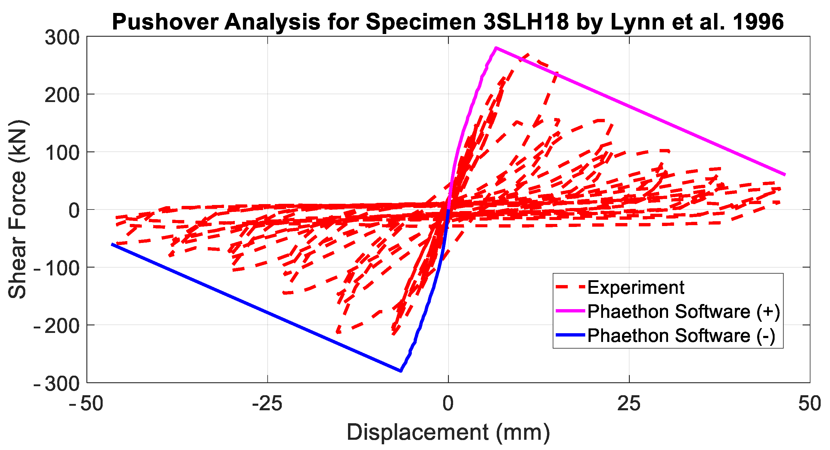
2.2.1. Pushover Seismic Analysis

To compute the lateral load resistance curve of a column shear span under lateral sway, a pushover analysis is performed. In the case of a brittle RC cantilever column within Phaethon, a sectional model (either rectangular or circular) based on modified compression field theory (MCFT) [15,16] is utilized, along with the lap splice model described previously. A progressively increasing lateral point load is applied at the cantilever’s tip (refer to Figure 3), and a single fiber element is assigned to cover the entire height of the cantilever column, with the user determining the number of Gauss–Lobatto integration points. Additionally, the user specifies the analysis step for the lateral load V to be applied during the pushover analysis, as well as the total number of steps until reaching maximum load. It is worth noting that the modified compression field theory in the fiber approach, as described by Bentz (2000) [17], cannot replicate the descending branch of shear-critical columns; hence, a load-control procedure was integrated into Phaethon. The maximum load in Phaethon corresponds to the load at the last step of algorithm convergence in incremental form. It is important to emphasize that, in actuality, the brittle column’s ascending response is followed by a descending branch indicative of progressive failure. However, the proposed algorithm is constrained by shear strength achievement. Following the peak load, the descending branch of the capacity curve is defined by a line connecting the maximum load point to the column’s axial failure point, quantified in terms of the drift estimate by Elwood and Moehle (2005) [18], along with 20% of the attained maximum load as residual load at axial failure.
For every point load applied at the tip of the cantilever (as shown in Figure 3), the corresponding shear force at the designated sections of the column (integration points) equals that load, resulting in a constant shear diagram. The flexural moment at the column’s base, denoted as M0, along with the moment distribution, are both derived from the lateral load value, leading to a constant shear force. The concentric axial load (either tensile or compressive) applied at the cantilever’s tip remains constant throughout the pushover analysis and along the length of the cantilever, ensuring each section of the column bears an axial force equivalent to the one applied at the tip. Following this methodology, the array of resisting section forces should converge to the previously defined section forces based on the moment, shear, and axial load diagram of the cantilever column under constant axial load and incrementally increasing lateral tip point loading. Once the convergence of section forces is achieved (via the Newton–Raphson iteration algorithm) along the length of the cantilever column to match the correct values based on the corresponding force diagrams due to the applied tip horizontal and axial load, the axial deformation εο, curvature φ, and shear strain γ are determined for each section. Integrating the curvatures (as depicted in Figure 3) across the shear span of the cantilever column yields the rotation of the cantilever column owing to flexure, which can be readily converted into lateral displacement due to flexure Δof by multiplying with the length of the shear span. Similarly, integrating the shear strains (illustrated in Figure 3) by sampling several sections (positions determined according to Gauss–Lobatto) along the length of the cantilever column (integration points) results in the lateral displacement Δosh due to the shear distortion mechanism of the cantilever column.
Finally, the rotation and displacement Δosl due to slip of the lap spliced tensile reinforcement (as depicted in Figure 3) are determined based on the closed-form solution of the governing equation of bond described in the preceding section (pull-out slip s of Figure 3 is determined according to Equations (10), (14) and (18)). All these simultaneous contributions (flexure, shear, and lap splice) are combined to define the total lateral displacement (i.e., Δo = Δof + Δosh + Δosl) of the cantilever column at each lateral load step and to derive the capacity curve of the column until maximum lateral load (as shown in Figure 3).

2.2.2. Cyclic Seismic Analysis

Numerical simulations under cyclic lateral action and constant axial load were conducted here using a nonlinear fibre beam-column element which considers the spread of plasticity. In this type of analysis, the longitudinal beam element uses a force-type formulation with linear moment distribution to derive a flexibility matrix for the element with progressing nonlinearity (step by step); the strain-displacement relationships are therefore defined implicitly after inversion of the flexibility matrix to obtain the stiffness. Assuming strain compatibility between materials comprising the member, the formulation samples sectional responses at selected integration points along the length. Such elements are available in FEDEAS Lab (2004) MATLAB toolbox [19,20,21,22]. As it can be seen in Figure 4, a single frame element is considered along the length of the cantilever column. A rotational spring is added below the element at the base, whose elastic stiffness was determined using the lap splice bar model of the previous section, which is embedded in Phaethon software (Version 1.0). Sampling of sectional response is performed at five Gauss–Lobatto integration points along the member length. The typical discretization of rectangular column sections is shown in Figure 4. At the sectional level, the Bernoulli hypothesis (plane sections remaining plane and normal to the axis of the member) is used to relate strains in the different fibres/layers (Figure 4) to the sectional curvature and longitudinal axis normal strain. Nonlinear uniaxial material laws are used to relate normal stress with normal strain in the fibres, thereby neglecting the effect of shear in modifying the principal orientations through the height of the cross-section, as Phaethon software considers. Sectional stress resultants (moment and axial load) are obtained from the equilibrium of the contributions of fibre stress resultants [19,20,21,22].
To account for material nonlinearity, the formulation employs uniaxial hysteretic nonlinear material stress–strain relations for confined concrete and common steel reinforcement [23,24]. The stress–strain relations are endowed with mathematical expressions for the envelope, for the hysteresis loops, and for the transition from the envelope to the unloading/reloading branches [25].
In 1988, Mander, Priestley, and Park [23] introduced a unified stress–strain method aimed at predicting the behavior of both pre-yield and post-yield phases in confined concrete members under axial compressive stresses. This approach adopts an equation proposed by Popovic in 1973 [26], originally devised to characterize the stress–strain response of unconfined concrete. The model is founded on a constant confining pressure, denoted as fl. The axial stress of the confined concrete, fc, for any given strain εc, correlates with the peak confined strength, fcc. The peak confined strength, fcc, is determined by a combination of the unconfined strength, fco, and the constant confining pressure, fl. The strain at peak confined strength, εcc, is expressed as a function of the strain at peak unconfined strength of concrete, εco, following the equation proposed by Richart et al. (1928) [27]. The cyclic variant of this uniaxial material model is illustrated in Figure 5.
The stress–strain relationship proposed by Menegotto and Pinto (1973) [24] provides a highly accurate depiction of the steel material’s behavior. It is crucial for the computational efficiency of frame model analysis that the model directly correlates stress to strain. However, the model’s drawback lies in its inability to reach the point of last unloading upon reloading in the same stress direction. Figure 6 illustrates the cyclic variant of this uniaxial material model. Both this steel model and the previously mentioned concrete model are utilized in simulating the cyclic lateral response of RC columns with short lap splices, as detailed in the subsequent section.

3. Results

The experimental campaign by Lynn et al. (1996) [28] was employed here for the validation of the proposed analytical model for both monotonic and cyclic seismic analyses. It includes eight full-scale specimens under constant axial load and increasing cyclic lateral displacement increments until failure. Three of the above specimens had short longitudinal bar lap splices (with a lap length of 20 times the longitudinal bar diameter) just above the top surface of the foundation block. Two of the latter specimens (see the column properties in Table 1 below) will be employed in this study for the correlation of the proposed methodology to the experimental results.
For the verification of the proposed pushover analysis, the first specimen of Table 1 (Spec. 3SLH18) is simulated. Figure 7 depicts the capacity curve of the latter specimen produced by Phaethon software with the corresponding cyclic experimental data of the cantilever configuration of the same specimen.
It can be seen that the numerical results are in good agreement with the experimental response. In Figure 8 below, based on the analytical model of the lap-spliced bar described previously, the strain, slip, and bond distributions of the bar at maximum lateral strength produced by Phaethon Windows software are given.
The simultaneous lateral displacement contributions (flexure, shear, and lap splice slip) until the maximum lateral strength of the above-considered specimen as determined by Phaethon Windows software are provided below in Figure 9.
In addition, for the verification of the proposed cyclic seismic analysis, the second specimen of Table 1 (Spec. 3SMD12) is employed. Figure 10 depicts the cyclic lateral response of the latter specimen produced by the FEDEAS Lab MATLAB toolbox [19,20,21,22] with the corresponding cyclic experimental data of the cantilever configuration of the same specimen. The constitutive cyclic material laws applied in the rectangular fiber section of the numerical model of Figure 4 and the properties of this specimen are depicted in Figure 5 and Figure 6.
It can be seen that the numerical results are in good agreement with the experimental response, which proves the effectiveness of implementing modeling not only for pushover analysis but also under cyclic seismic action too.

4. Discussion

The review of the state of the art regarding interpretation and consistent modeling of reinforced concrete column under lateral loads leaves a lot to be desired: improved response estimation of the behavior of columns that are susceptible to shear failure after flexural yielding; better procedures to estimate shear strength, and the pattern of degradation thereof with increasing displacement ductility; the need to account for reinforcement slip and its effects on stiffness and deformation capacity; the shape of the hysteresis loops; the detrimental effects of axial load at large displacement limits; the drift capacity of structural elements and the magnitude of deformation (drift ratio) associated with milestone events in the response curve of the column member are open issues that need to be settled before the performance-based assessment framework may be considered complete and dependable [29,30,31,32,33,34,35,36,37]. RC columns with short lap splices built in the early 1970s or before are known to have deficient seismic strength and ductility. A numerical model based on local bond–slip analytical models derived from isolated anchored bars through the closed-form solution of the differential equation of bond was developed. The proposed model is satisfactorily correlated to experimental data from cyclic loading tests on RC columns with deficient lap splices performed by Lynn et al. 1996 [28]. It can be seen that the strength of short lap splices, the failure mode, and the column’s lateral resistance and deformation are in good agreement with the experimental results both under monotonic and cyclic seismic analyses.

5. Conclusions

To sum up, a closed-form solution of bond equations governing the behavior of lap-spliced bars of an RC column under lateral sway was developed considering nonlinearity in the bond–slip law. The latter was embedded in a Windows-based software called Phaethon for fiber-based, distributed nonlinearity analysis of prismatic frame elements undergoing lateral sway such as would occur during an earthquake. Moment, shear, and axial load interaction were considered in calculating the resistance curve for RC columns that underwent flexure shear or purely shear-dominated mode of failure, and the distinct contributions of the many contributing sources of column deformation (curvature, shear angle, axial elongation, lap splice slip) were illustrated through the developed algorithm. The latter software offers the possibility of obtaining the rotation due to the pull-out of the lap splice occurring in the critical section of the column. The software also resolves strain, slip, and bond distributions along the lap splice length. Finally, the proposed analytical model can also solve the column state of stress under full cyclic load reversals for flexure-dominated response conditions of RC columns with deficient lap splices at the base of the column. The correlation to the experimental results of the proposed numerical model is satisfactory, but further validation is necessary with more experimental results, including shake-table tests of RC columns with short lap splices. Performance-based earthquake engineering’s main objective is to define an “acceptable” probability of collapse. Collapse shall be quantified as realistically as possible, using nonlinear dynamic analysis, which incorporates several suites of ground motions. A comprehensive set of guidelines will form the starting point for addressing the complexity inherent in nonlinear softening responses under large displacements and deformations and will contribute to the acceptance of nonlinear response studies in professional practice. The deployment of a new class of column models such as those presented in this study that account for localized phenomena such as shear and lap splice slip in a consistent iterative element formulation will help minimize the non-convergence issues that arise with the large collection of zero-length nonlinear spring and plastic hinge elements currently in use in nonlinear column response simulations.

Funding

This research was partially conducted with the financial support of the Alexander S. Onassis Public Benefit Foundation which provided K.G.M. with a triennial scholarship (Scholarship Code: F ZI 086-1 2012-2013/01/09/2012–29/02/2016) to pursue a Ph.D. degree in Civil Engineering at the University of Cyprus.

Data Availability Statement

All included data in this study are available upon request from the corresponding author.

Acknowledgments

The author would like to thank the Alexander S. Onassis Public Benefit Foundation whose financial support is greatly appreciated. The present research work is partially based on the Ph.D. thesis of K.G.M. [9].

Conflicts of Interest

The author declares no conflicts of interest.

References

  1. Melek, M.; Wallace, J.W. Cyclic behavior of columns with short lap splices. Struct. J. 2004, 101, 802–811. [Google Scholar]
  2. Cho, J.Y.; Pincheira, J.A. Inelastic analysis of reinforced concrete columns with short lap splices subjected to reversed cyclic loads. ACI Mater. J. 2006, 103, 280. [Google Scholar]
  3. Chail, Y.H.; Priestley, M.N.; Seible, F. Seismic retrofit of circular bridge columns for enhanced flexural performance. Struct. J. 1991, 88, 572–584. [Google Scholar]
  4. Sun, Z.; Priestley, M.J.N.; Seible, F. Diagnostics and Retrofit of Rectangular Bridge Columns for Seismic Loads; Department of Applied Mechanics and Engineering Sciences, University of California: San Diego, CA, USA, 1993. [Google Scholar]
  5. Reyes, O.; Pincheira, J.A. R/C columns with lap splices subjected to earthquake. In ASCE Structures Congress; ASCE: Reston, VA, USA, 1999; pp. 369–372. [Google Scholar]
  6. Tariverdilo, S.; Farjadi, A.; Barkhordary, M. Fragility curves for reinforced concrete frames with lap-spliced columns. Int. J. Eng. Trans. A Basics 2009, 22, 213. [Google Scholar]
  7. Zhang, Y.; Tien, I. Methodology for regularization of force-based elements to model reinforced concrete columns with short lap splices. ASCE J. Eng. Mech. 2020, 146, 04020073. [Google Scholar] [CrossRef]
  8. Tastani, S.P.; Brokalaki, E.; Pantazopoulou, S.J. State of Bond along Lap-Splices. ASCE J. Struct. Eng. 2015, 141, 04015007. [Google Scholar] [CrossRef]
  9. Megalooikonomou, K.G. Modeling the Behavior of Shear-Critical Reinforced Concrete Columns under Lateral Loads. Ph.D. Thesis, Department of Civil and Environmental Engineering, Faculty of Engineering, University of Cyprus, Nicosia, Cyprus, December 2019. [Google Scholar] [CrossRef]
  10. Megalooikonomou, K.G. Seismic Assessment and Retrofit of Reinforced Concrete Columns, 1st ed.; Cambridge Scholars Publishing: Newcastle upon Tyne, UK, 2019; p. 387. [Google Scholar]
  11. Megalooikonomou, K.G. PHAETHON: Software for Analysis of Shear-Critical Reinforced Concrete Columns. Mod. Appl. Sci. 2018, 12, 1–22. [Google Scholar] [CrossRef]
  12. Megalooikonomou, K.G.; Tastani, S.P.; Pantazopoulou, S.J. Effect of Yield Penetration on Column Plastic Hinge Length. Eng. Struct. 2018, 156, 161–174. [Google Scholar] [CrossRef]
  13. Tassios, T.P.; Yannopoulos, P.J. Analytical studies on reinforced concrete members under cyclic loading based on bond-slip relationships. ACI Mater. J. 1981, 78, 206–216. [Google Scholar]
  14. Filippou, F.; Popov, E.; Bertero, V. Modeling of R/C joints under cyclic excitations. ASCE J. Struct. Eng. 1983, 109, 2666–2684. [Google Scholar] [CrossRef]
  15. Vecchio, F.J.; Collins, M.P. The modified compression field theory for reinforced concrete elements subjected to shear. ACI J. Proc. 1986, 83, 219–231. [Google Scholar]
  16. Vecchio, F.J.; Collins, M.P. Predicting the Response of Reinforced Concrete Beams Subjected to Shear Using Modified Compression Field Theory. ACI Struct. J. 1988, 85, 258–268. [Google Scholar]
  17. Bentz, E.C. Sectional Analysis of Reinforced Concrete Members. Ph.D Thesis, Department of Civil Engineering, University of Toronto, Toronto, ON, Canada, 2000. [Google Scholar]
  18. Elwood, K.J.; Moehle, J.P. Axial Capacity Model for Shear-Damaged Columns. ACI Struct. J. 2005, 102, 578–587. [Google Scholar]
  19. Filippou, F.C.; Fenves, G.L. Methods of analysis for earthquake-resistant structures. In Earthquake Engineering: From Engineering Seismology to Performance-Based Engineering; Bozorgnia, Y., Bertero, V.V., Eds.; CRC Press: Boca Raton, FL, USA, 2004. [Google Scholar]
  20. Filippou, F.C.; Constantinides, M. FEDEAS Lab—Getting Started Guide and Simulation Examples, NEESgrid Report 2004-22 and SEMM Report 2004-05. 2004. Available online: https://fedeas.net/ (accessed on 10 February 2024).
  21. Mathworks. MATLAB: User’s Guide (R2018b); Mathworks: Portola Valley, CA, USA, 2018. [Google Scholar]
  22. Spacone, E.; Filippou, F.C.; Taucer, F.F. Fibre beam–column model for non-linear analysis of R/C frames: Part, I. Formulation. Earthq. Eng. Struct. Dyn. 1996, 25, 711–725. [Google Scholar] [CrossRef]
  23. Mander, J.B.; Priestley, M.J.N.; Park, R. Theoretical stress-strain model for confined concrete. J. Struct. Eng. ASCE 1988, 114, 1804–1826. [Google Scholar] [CrossRef]
  24. Menengotto, M.; Pinto, E. Method of Analysis for Cyclically Loaded Reinforced Concrete Plane Frames Including Changes in Geometry and Non-elastic Behavior of Elements under Combined Normal Force and Bending. In Proceedings of the IABSE Symposium on Resistance and Ultimate Deformability of Structures Acted on by Well-Defined Repeated Loads, Final Report, Lisbon, Portugal; 1973; pp. 15–22. [Google Scholar]
  25. Karsan, I.D.; Jirsa, J.O. Behavior of concrete under compressive loadings. J. Struct. Div. 1969, 95, 2543–2564. [Google Scholar] [CrossRef]
  26. Popovics, S. A numerical approach to the complete stress-strain curves for concrete. Cem. Concr. Res. 1973, 3, 583–599. [Google Scholar] [CrossRef]
  27. Richart, F.E.; Brandtzaeg, A.; Brown, R.L. A study of the failure of concrete under combined compressive stresses. In Engineering Experiment Station Bulletin No. 185; University of Illinois: Urbana, IL, USA, 1928. [Google Scholar]
  28. Lynn, A.C.; Moehle, J.P.; Mahin, S.A.; Holmes, W.T. Seismic Evaluation of Existing Reinforced Concrete Columns. Earthq. Spectra 1996, 12, 715–739. [Google Scholar] [CrossRef]
  29. Megalooikonomou, K.G.; Beligiannis, G.N. Random Forests Machine Learning Applied to PEER Structural Performance Experimental Columns Database. Appl. Sci. 2023, 13, 12821. [Google Scholar] [CrossRef]
  30. Elwood, K.J.; Moehle, J.P. Drift Capacity of Reinforced Concrete Columns with Light Transverse Reinforcement. Earthq. Spectra 2005, 21, 71–89. [Google Scholar] [CrossRef]
  31. Panagiotakos, T.B.; Fardis, M.N. Deformations of reinforced concrete members at yielding and ultimate. ACI Struct. J. 2001, 98, 135–148. [Google Scholar]
  32. Priestley, M.J.N.; Seible, F.; Calvi, M. Seismic Design and Retrofit of Bridges; J. Wiley & Sons Inc.: New York, NY, USA, 1996. [Google Scholar]
  33. Pujol, S.; Ramirez, J.A.; Sozen, M.A. Drift Capacity of Reinforced Concrete Columns Subjected to Cyclic Shear Reversals; Seismic Response of Concrete Bridges, SP-187; American Concrete Institute: Farmington Hills, MI, USA, 1999; pp. 255–274. [Google Scholar]
  34. Sezen, H.; Moehle, J.P. Seismic Tests of Concrete Columns with Light Transverse Reinforcement. ACI Struct. J. 2006, 103, 842–849. [Google Scholar]
  35. Kim, C.; Park, H.; Eom, T. Effects of type of bar lap splice on reinforced concrete columns subjected to cyclic loading. ACI Struct. J. 2019, 116, 183–194. [Google Scholar] [CrossRef]
  36. Lee, C.S.; Han, S.W. Cyclic behaviour of lightly-reinforced concrete columns with short lap splices subjected to unidirectional and bidirectional loadings. Eng. Struct. 2019, 189, 373–384. [Google Scholar] [CrossRef]
  37. Seifi, A.; Hosseini, A.; Marefat, M.S.; Khanmohammadi, M. Seismic retrofitting of old-type RC columns with different lap splices by NSM GFRP and steel bars. Struct. Des. Tall Spec. Build. 2018, 27, e1413. [Google Scholar] [CrossRef]
Figure 1. (a) Stress–strain law of steel bar; (b) local bond slip law.
Constrmater 04 00018 g001
Figure 2. (a) Elastic lap splice bar response while bond–slip law remains elastic; (b) elastic lap splice bar response with bond plastification.
Constrmater 04 00018 g002
Figure 3. Pushover Analysis in Phaethon Windows software (Version 1.0) [13] (ycz is the depth of the compression zone, cover is the concrete cover of the cross-section and d is the total depth of column’s cross-section).
Constrmater 04 00018 g003
Figure 4. (a) Numerical model for RC columns with short lap splices under cyclic lateral action and constant axial load; (b) section discretization in fibers/layers.
Constrmater 04 00018 g004
Figure 5. Cyclic uniaxial material model by Mander et al. (1988) [23].
Constrmater 04 00018 g005
Figure 6. Cyclic uniaxial material model by Menegotto and Pinto (1973) [24].
Constrmater 04 00018 g006
Figure 7. Correlation of the proposed pushover analysis with the experimental results by Lynn et al. (1996) [28].
Constrmater 04 00018 g007
Figure 8. Strain, slip, and bond distributions along the lap splice length of specimen 3SLH18 by Lynn et al. 1996 [28].
Constrmater 04 00018 g008
Figure 9. Lateral displacement contributions (flexure, shear, lap splice slip) from pushover analysis of Specimen 3SLH18 by Lynn et al. 1996 [28] (56 pushover steps of 5 kN lateral load step each).
Constrmater 04 00018 g009
Figure 10. Correlation of the proposed cyclic lateral analysis with the experimental results by Lynn et al. 1996 [28].
Constrmater 04 00018 g010
Table 1. Details of RC columns with short lap splices (units: mm, MPa, kN).
Case Axial Load (kN) Width (mm)–Depth (mm) Shear Span (mm)–
Lap Splice Length (mm)
Clear Cover (mm)Concrete Strength (MPa)Number–Diameter (mm)–Reinforcing Ratio of Longitudinal BarsYielding–Ultimate Strength of Long. Bars (MPa) Yielding Strength (MPa)–Spacing (mm)–Diameter (mm)–Ratio of Transv. Reinf.
Lynn et al. (1996) [28]–(Spec. 3SLH18) 503457.2
457.2
1473.2
635
38.126.98
31.75
0.0303
330.96
496
399.91
457.2
9.525
0.00082
Lynn et al. (1996) [28]–(Spec. 3SMD12) 1512457.2
457.2
1473.2
635
38.125.58
31.75
0.0303
330.96
496
399.91
304.8
9.525
0.0021
Disclaimer/Publisher’s Note: The statements, opinions and data contained in all publications are solely those of the individual author(s) and contributor(s) and not of MDPI and/or the editor(s). MDPI and/or the editor(s) disclaim responsibility for any injury to people or property resulting from any ideas, methods, instructions or products referred to in the content.

