
Concrete Damage Plasticity Model Application to Predict Stress–Strain Behavior of Impermeable Strata in Deep Rock Salt Deposits


Abstract
1. Introduction
- Calibration of Concrete damage plasticity model parameters for sylvinite, carnallite, and rock salt using published laboratory data on strength, deformation, and fracture energy.
- Development of a plane-strain finite-element model of a mining panel that couples Concrete damage plasticity for impermeable strata with N2PC-MCT viscoplastic creep for long-term pillar deformation, and validation of this model against observed ground-surface subsidence and chamber convergence.
- Analysis of stress–strain evolution and crack localization in the stratified impermeable strata under scenarios with and without backfilling, and comparison with a hypothetical homogeneous impermeable strata representation to isolate the role of stiffness contrasts and interlayer bonding.
- An approximate analytical model of a multilayer beam is used to compare with numerical results and to additionally confirm stress concentration in stiff intermediate layers of impermeable strata.
1.1. Multilayer Systems and Bending Behavior
1.2. Problem Statement
2. Materials and Methods
- Obtaining input parameters for the Concrete model for sylvinite, carnallite, and rock salt from published laboratory data;
- Implementing Concrete damage-plasticity (for fracture and softening) together with N2PC-MCT viscoplastic creep (for long-term pillar deformation) in a plane-strain finite-element model of a mining panel;
- Validating numerical results against measured surface subsidence and chamber convergence;
- Analyzing stress–strain evolution and crack localization for stratified and homogeneous impermeable strata representations;
- Cross-validating numerical results with an analytical multilayer beam bending solution.
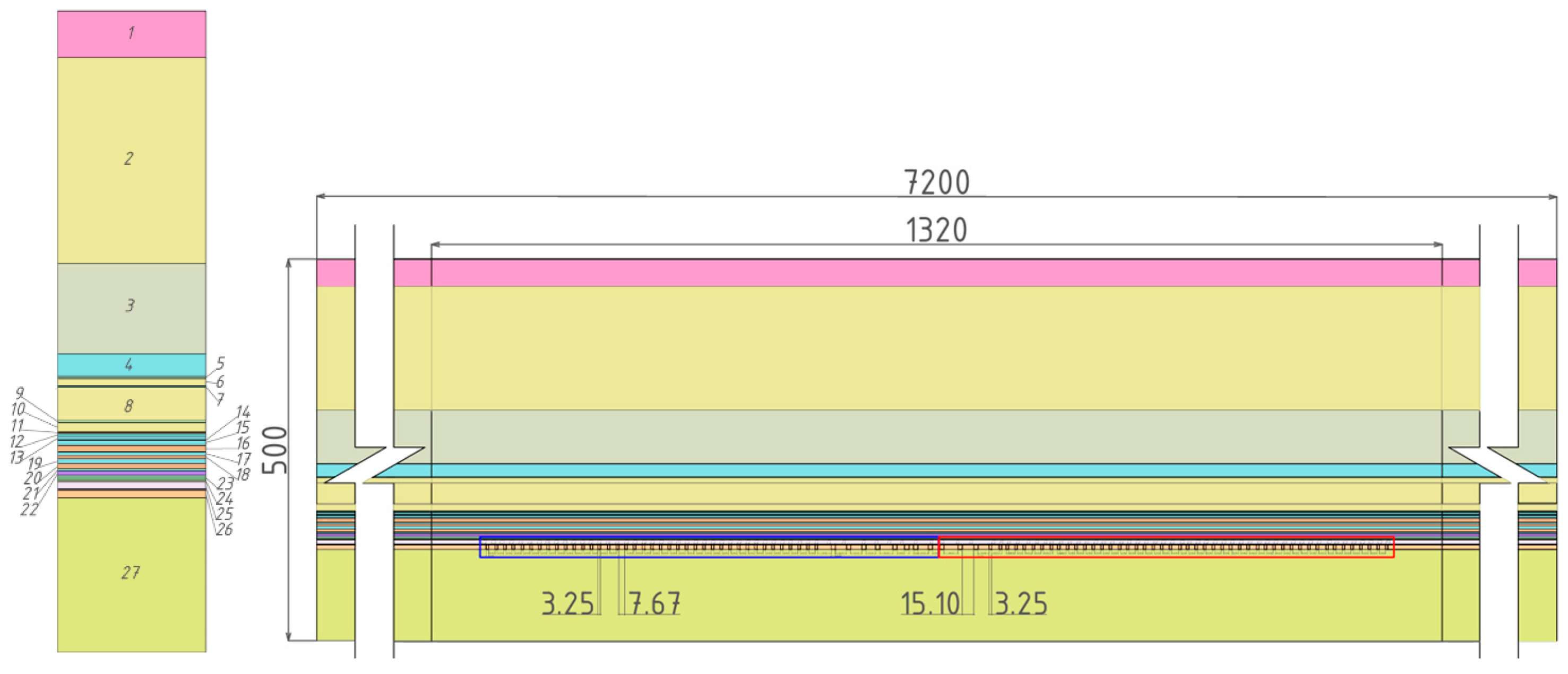
2.1. Site Description and Geological Setting
- Layer 1: sedimentary rocks (0–36 m),
- Layers 2–8: alternating clayey-marl strata and rock salt (36–319.2 m),
- Layers 9–23: alternating carnallite and rock salt (319.2–366 m),
- Layers 24–26: sylvinite (366–379.6 m),
- Layer 27: underlying sylvinite and rock salt (379.6–500 m).
2.2. Laboratory Data and Calibration of Concrete Model Parameters
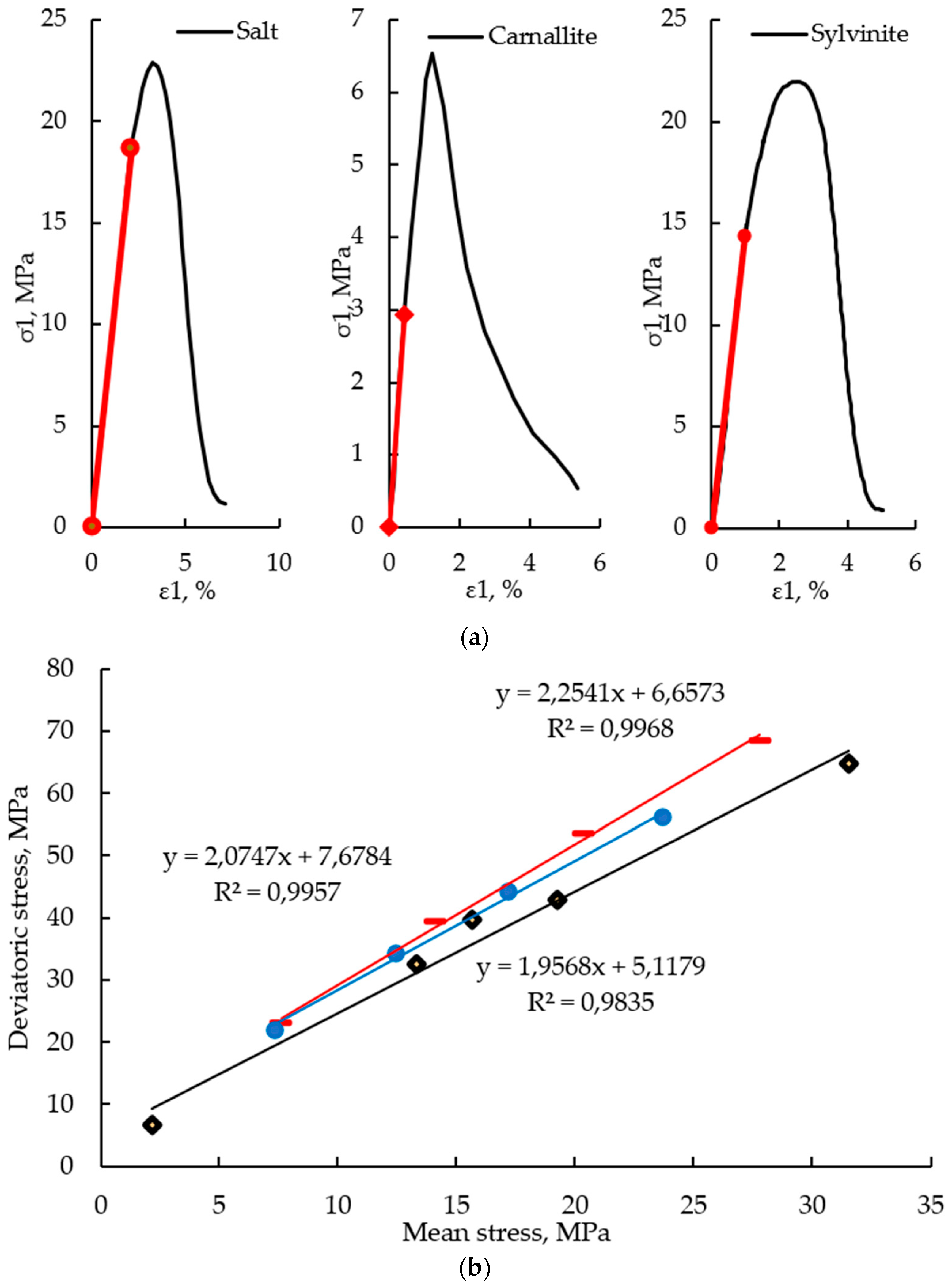
- Virtual tests and iterative optimization. The Concrete model parameters are iteratively adjusted using virtual simulations of uniaxial compression, tension, and triaxial compression. Numerical curves are fitted to experimental envelopes, with particular attention to lateral-compression conditions that represent in situ stress states. Figure 2 illustrates averaged uniaxial compression curves (a) and failure envelopes (b) for sylvinite, carnallite, and rock salt used in calibration.
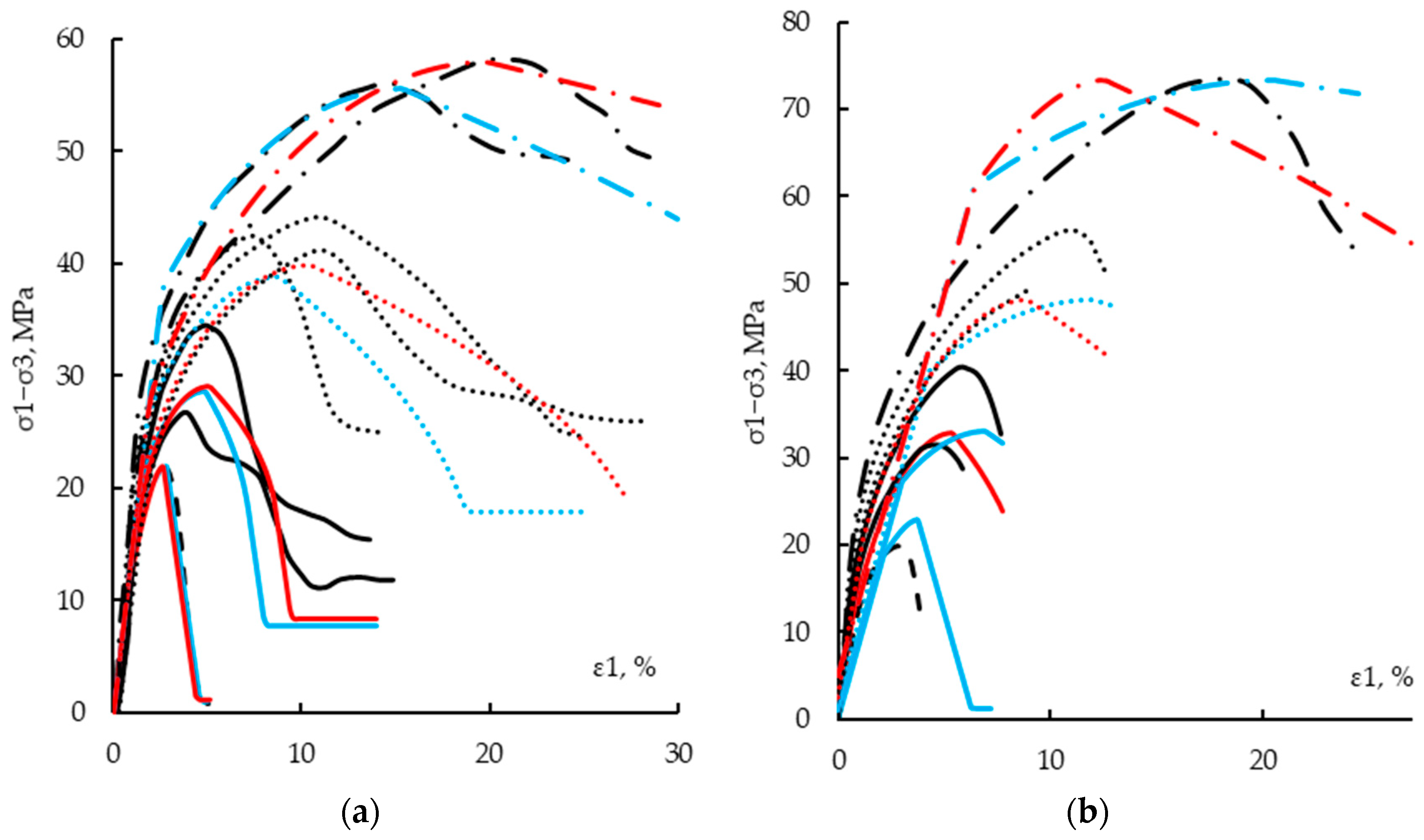
- Verification against laboratory data. After calibration, model performance is verified by comparing simulated and experimental stress–strain diagrams for sylvinite and rock salt under uniaxial and triaxial loading. The calibrated model reproduces the dependence of peak strength on confining pressure and post-peak softening behavior. All calibrated parameters are summarized in Table 1.
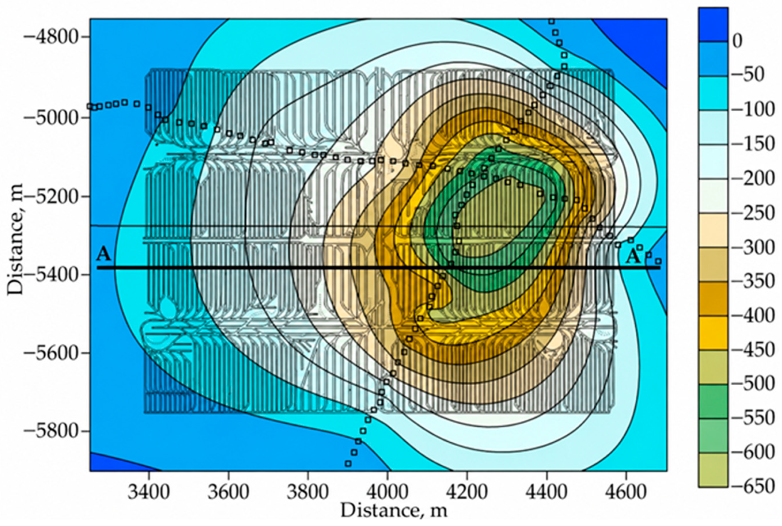
2.3. Numerical Model of the Panel
2.4. Constitutive Models
- Concrete damage-plasticity model [21,22]: The built-in Concrete damage-plasticity model is used for impermeable strata layers and other rock units where crack formation is of interest. Key features include separate tensile and compressive fracture energies (Gt and Gc), a brittle–ductile transition parameter, a post-peak softening law tied to fracture energy, and damage variables linked to plastic strain and energy dissipation. Tensile cracking is assumed to initiate when local tensile stress reaches the tensile strength. Thereafter, damage and softening govern stiffness degradation and fracture energy dissipation. Crack propagation in the finite-element model is represented by progressive damage localization and stiffness loss, consistent with continuum damage mechanics.
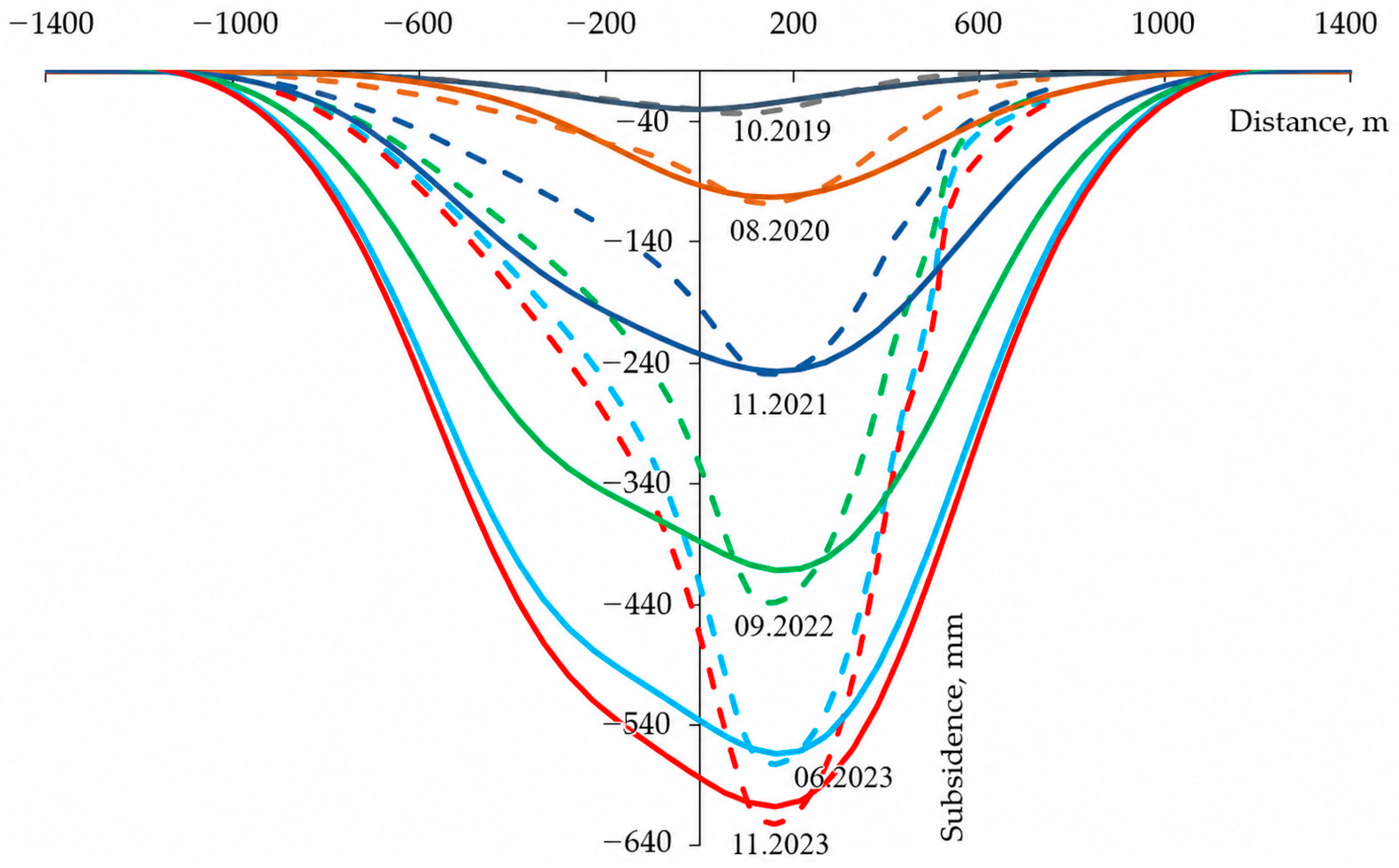
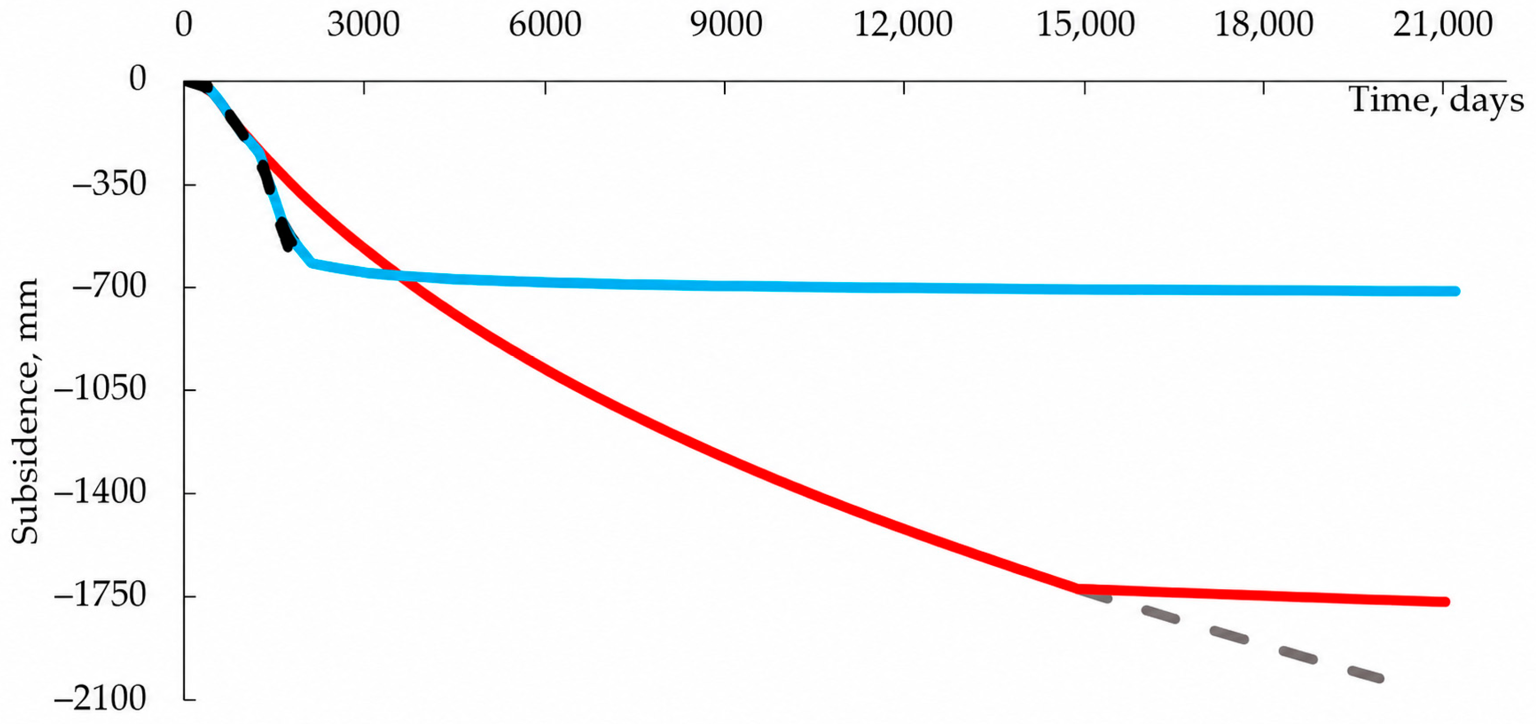
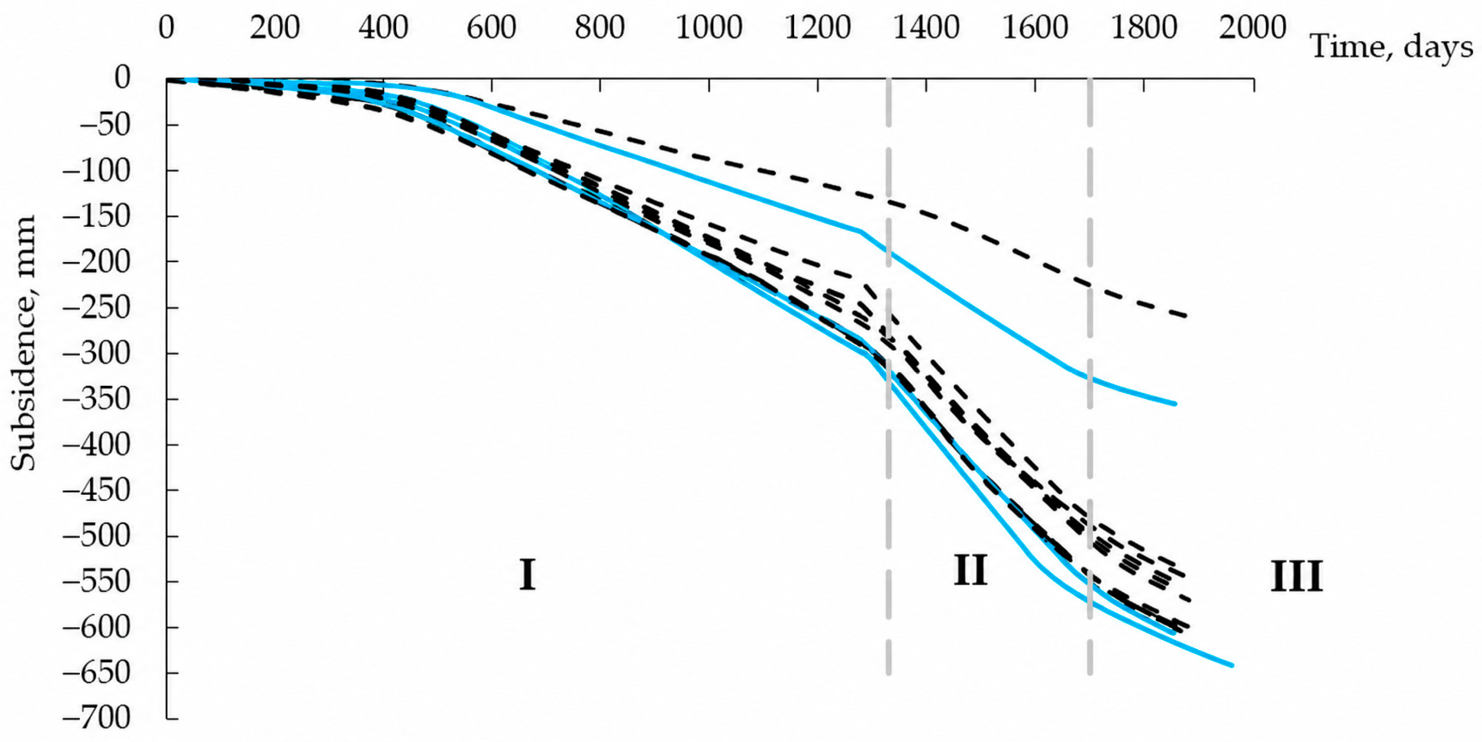
- N2PC-MCT viscoplastic model: The N2PC-MCT viscoplastic creep model, implemented as a user-defined soil model in the finite-element code, is used to represent long-term pillar creep. It includes a power-law creep component and a plastic failure mechanism calibrated to reproduce long-term subsidence. Creep parameters are validated to ensure that the simulated surface subsidence matches field measurements.
2.5. Damage, Crack, and Interface Slip Criteria
2.6. Model Calibration and Validation Against Subsidence
2.7. Computational Scenarios
2.8. Analytical Multilayer Beam Model
3. Results
3.1. Laboratory Test Data Verification
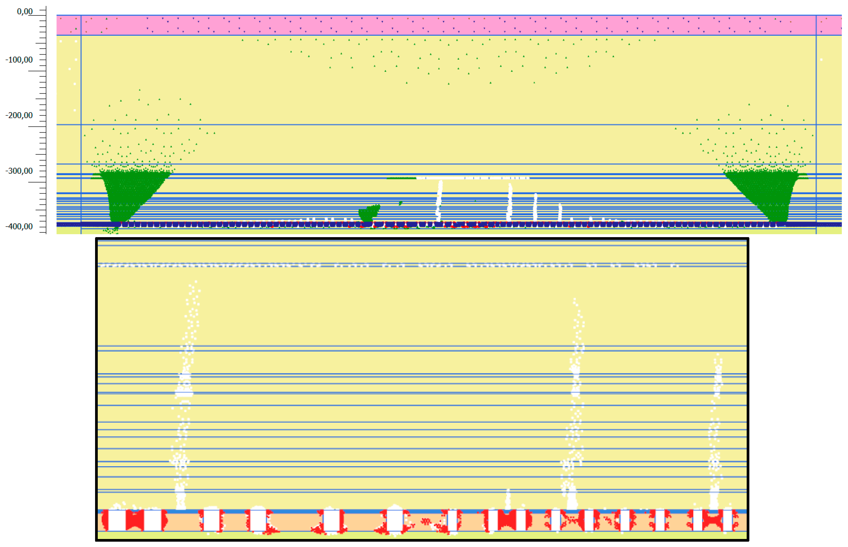
3.2. Long-Term Impermeable Strata Response and Damage Evolution
- At about 27 years, there is practically no tensile failure in impermeable strata.
- At about 37 years, initial tensile failure zones appear in rock salt layers at depths −286.5 to −328.3 m, indicating crack initiation. Deformation in peripheral zones extends into overlying clay-dolomite layers.
- By around 44 years, failure zone density increases markedly within the same depth interval, representing progressive crack formation in a stiff central salt layer. This period coincides with significant chamber wall closure, which tends to slow down further crack development due to increased confinement and contact.
3.3. Homogeneous Versus Stratified Impermeable Strata and Stress Concentration
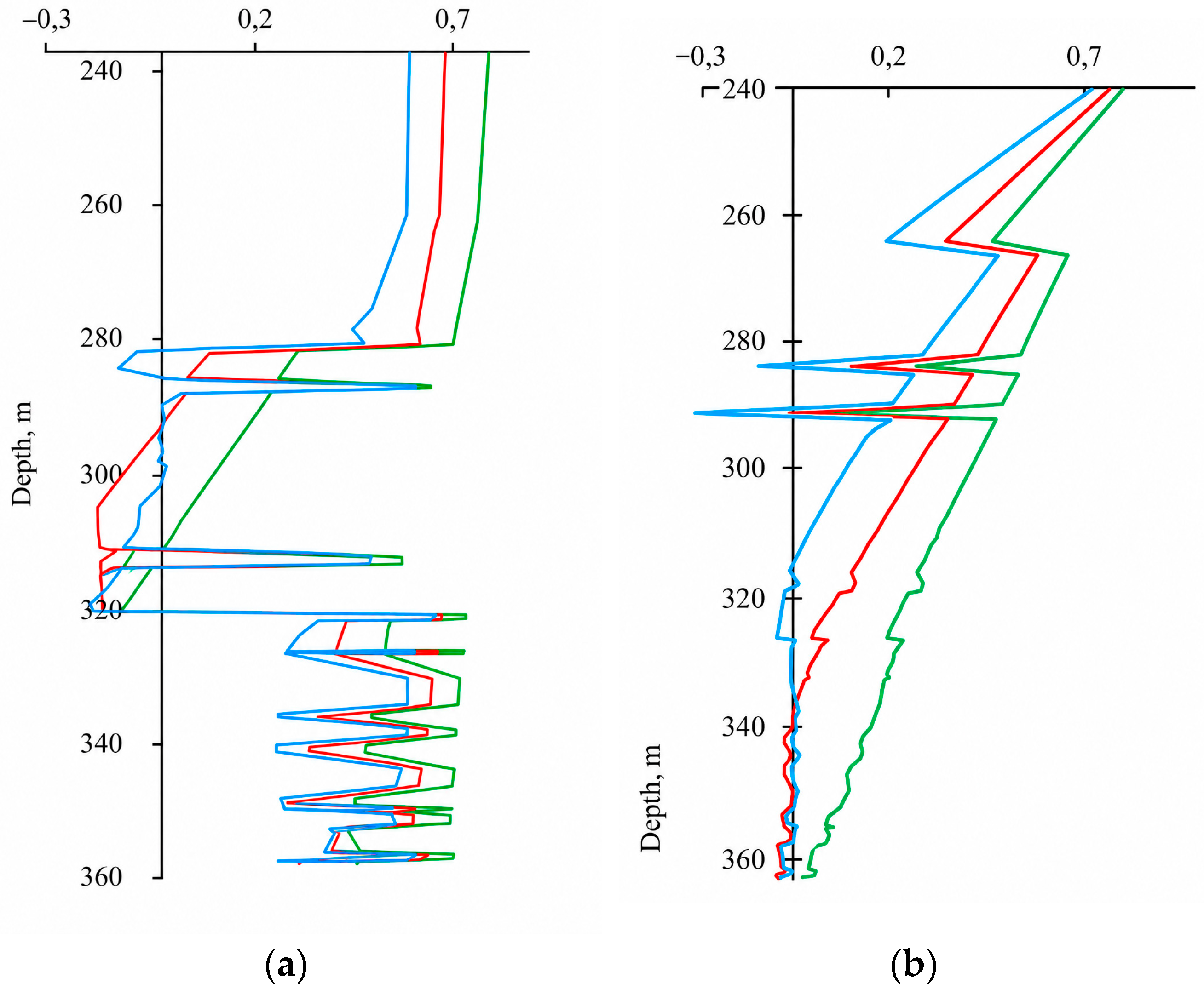
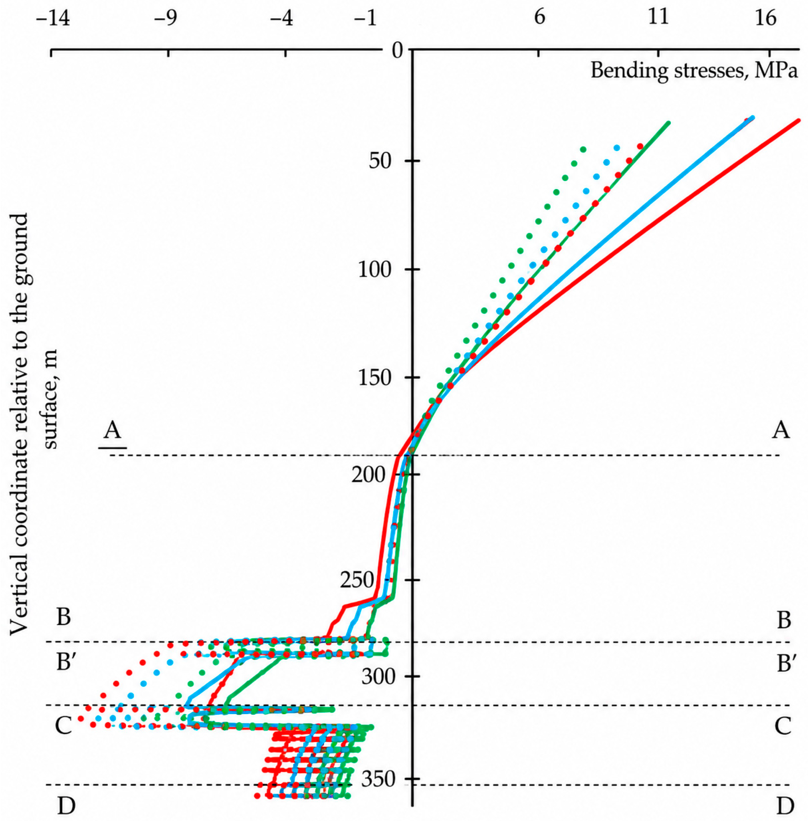
3.4. Comparison with Analytical Multilayer Beam Solution
- The neutral axis tends to shift toward stiffer layers with higher flexural rigidity;
- Bending stress jumps occur at interfaces where stiffness changes;
- Thin, stiff layers experience larger tensile stress increments than neighboring softer layers.
4. Discussion
- Plane-strain simplification does not reflect three-dimensional effects associated with panel geometry and local structural features;
- IR content and mechanical properties of overburden and impermeable strata layers are represented in a simplified manner, with limited site-specific calibration data;
- Interface elements approximate interlayer slip but do not explicitly model through-going delamination;
- Predictions beyond the onset of widespread chamber contact (after about 41 years) are less reliable because contact mechanics are not fully represented;
- The Concrete damage-plasticity model does not incorporate salt-specific processes such as dilatancy, healing, and the coupled creep-damage evolution present in advanced rock-salt constitutive models (e.g., Hou/Lux). Hence, the numerical predictions are strictly valid for the investigated tensile-failure mode and timescale and should not be extrapolated to compressive long-term creep-dominated scenarios without careful scrutiny.
5. Conclusions
- The identification of layers prone to conductive fractures initiation should be based on their capacity to concentrate tensile stress during bending. This is governed by two factors: (1) a high stiffness contrast relative to neighboring layers and (2) sufficient layer thickness. Together, these parameters control the contribution to the composite section’s moment of inertia (Equation (4)) and, consequently, the resulting bending stresses (Equation (5)). Prior to mining, integrated geophysical profiling—using surface seismic reflection calibrated with acoustic broadband borehole logging—should be employed to construct a geological-geomechanical model (GGM) to map such critical layers [2]. During mining operations, routine surface subsidence measurements, specifically the maximum displacement, provide direct input for the analytical multilayer-beam solution (Equations (2)–(6)). This model estimates the evolving tensile stress and bending within the pre-identified stiff, thick layers. When the calculated safety factor approaches a critical value, a non-invasive monitoring protocol should be initiated, which could include enhanced monitoring (e.g., repeat seismic surveys) or measures to reduce bending effects in the impermeable strata layers (e.g., prioritized backfilling of corresponding chambers). To mitigate the risk of crack development in the impermeable strata, surface settlement above the mined-out chambers should be kept as uniform as possible, avoiding pronounced local extremes.
- The Concrete damage-plasticity model, combined with the N2PC-MCT viscoplastic creep model, reproduces laboratory behavior of sylvinite, carnallite, and rock salt and provides a realistic representation of impermeable strata stress–strain evolution when calibrated to subsidence measurements at the Upper Kama potash deposit. The adopted CDP model does not capture dilatancy, healing, or the full creep-damage interaction; it is therefore limited to the tensile-dominated failure problem analyzed here and should not be regarded as a universal salt rheology model.
- Long-term numerical simulations up to 50 years show that, without backfill, tensile damage in the impermeable strata is mainly localized in a stiff central salt layer at depths of about −286.5 to −328.3 m. Most cracks appear roughly between 33 and 37 years after mining begins. In the case of backfill, propagation of tensile cracks in impermeable strata practically stops after termination of mining.
- Comparison of stratified and homogeneous impermeable strata models and results of an analytical multilayer beam model demonstrates that stiffness contrasts and composite bending of the impermeable strata cause concentration of tensile stresses in stiff intermediate layers. That explains the central-layer cracking observed in numerical simulations.
- Preliminary nature of quantitative estimates. The 2D numerical results suggest that stiff central layers of the impermeable strata may be potential zones for tensile crack initiation during long-term room-and-pillar mining. However, owing to the adopted simplifications, including plane strain and uniform distribution of insoluble residue, the quantitative estimates should be regarded as preliminary. Reliable hazard assessment will require three-dimensional modeling that accounts for the actual chamber geometry, local rock properties, and delamination mechanisms.
- For more detailed analysis of late failure stages and possible delamination, further development of models is needed, including three-dimensional simulations, improved characterization of rock properties, and possibly hybrid discrete-continuum approaches.
Author Contributions
Funding
Institutional Review Board Statement
Informed Consent Statement
Data Availability Statement
Conflicts of Interest
References
- Baryakh, A.A.; Gubanova, E.A. On flood protection measures for potash mines. J. Min. Inst. 2019, 240, 613–620. [Google Scholar] [CrossRef]
- Kashnikov, Y.; Ermashov, A.; Efimov, A. Geological and geomechanical model of the verkhnekamsk potash deposit site. J. Min. Inst. 2019, 237, 259–267. [Google Scholar] [CrossRef]
- Lomakin, I.; Tsayukov, A.; Evseev, A. Physical and mathematical modeling of rib pillar deformation and failure processes. Perm Sci. Cent. J. 2021, 14, 47–53. [Google Scholar] [CrossRef]
- Pankov, I.; Anikin, V.; Beltyukov, N.; Evseev, A.; Kuzminykh, V.; Lomakin, I.; Morozov, I.; Toksarov, V.; Udartsev, A. Studying the deformation and failure of salt rocks for geomechanical assessing the stability of elements of the system for the mining at potash deposits. Perm Sci. Cent. J. 2022, 3, 14–24. [Google Scholar] [CrossRef]
- Tatarkin, A.V. Prediction procedure for sinkholes in terms of the Upper Kama potassium-magnesium salt deposit. Min. Inf. Anal. Bull. 2020, 2020, 121–132. [Google Scholar] [CrossRef]
- Konstantinova, S.A.; Spirkov, V.L.; Kartashov, Y.M. Creep of rock salt samples under uniaxial compression. Sov. Min. Sci. USSR 1979, 15, 463–468. [Google Scholar] [CrossRef]
- Konstantinova, S.A.; Pestrenin, V.M.; Pestrenina, I.V. On various types of approximation of creep curves of salt rock samples. University Bulletin. Min. J. 2007, 4, 92–98. [Google Scholar]
- Petrov, D.N.; Abashin, V.I.; Karasev, M.A.; Selikhov, A.A. Non-destructive testing applicability in rock mass strength estimation in underground mine at the Gremyachinsk deposit. Min. Inf. Anal. Bull. 2024, 12, 227–244. [Google Scholar] [CrossRef]
- Pulatsu, B.; Gonen, S.; Erdogmus, E.; Lourenço, P.B.; Lemos, J.V.; Hazzard, J. Tensile Fracture Mechanism of Masonry Wallettes Parallel to Bed Joints: A Stochastic Discontinuum Analysis. Modeling 2020, 1, 6. [Google Scholar] [CrossRef]
- Zherlygina, E.S.; Kuranova, M.E.; Gusev, V.N.; Odintsov, E.E. Identification of hazardous sites based on studying the development of man-made fractures within the rock mass. Russ. Min. Ind. 2025, 1, 162–169. [Google Scholar] [CrossRef]
- Belyakov, N.A.; Emelyanov, I.A. Inclusion of rock mass fracturing in determination of in situ stress state by overcoring using multi-component displacement sensor. MIAB Min. Inf. Anal. Bull. 2024, 12, 145–164. [Google Scholar] [CrossRef]
- Demenkov, P.A.; Basalaeva, P. Regularities of Brittle Fracture Zone Formation in the Zone of Dyke Around Horizontal Mine Workings. Eng 2025, 6, 91. [Google Scholar] [CrossRef]
- Baryakh, A.; Tsayukov, A. Elastic-viscoplastic deformation models of salt rocks. Frat. Ed Integrità Strutt. 2024, 18, 191–209. [Google Scholar] [CrossRef]
- Kashnikov Yu, A.; Ermashov, A.O.; Lebedeva, O.O. 3D geomechanical modeling as the basis for solving complex problems of potassium salt development safety. Miner. Min. Eng. 2019, 3, 30–38. [Google Scholar] [CrossRef]
- Rybak, J.; Khayrutdinov, M.M.; Kuziev, D.A.; Kongar-Syuryun, C.B.; Babyr, N.V. Prediction of the geomechanical state of the rock mass when mining salt deposits with stowing. J. Min. Inst. 2022, 253, 61–70. [Google Scholar] [CrossRef]
- Belikov, A.A.; Belyakov, N.A. Method for ensuring geomechanical safety during undermining of water-protective strata. Sustain. Dev. Mt. Territ. 2025, 17, 115–125. [Google Scholar] [CrossRef]
- Belyakov, N.A.; Belikov, A.A. Prediction of the integrity of the water-protective stratum at the Verkhnekamskoye potash ore deposit. Min. Inf. Anal. Bull. 2022, 33–46. [Google Scholar] [CrossRef]
- Kovalskii, E.R.; Gromtsev, K.V. Development of the technology of stowing the developed space during mining. J. Min. Inst. 2022, 254, 202–209. [Google Scholar] [CrossRef]
- Baryakh, A.A.; Devyatkov, S.Y.; Denkevich, E.T. Mathematical modeling of displacement during the potash ores mining by longwall faces. J. Min. Inst. 2023, 259, 13–20. [Google Scholar] [CrossRef]
- Baryakh, A.A.; Samodelkina, N.A. Water-Tight Stratum Rupture under Large-Scale Mining. Part II. J. Min. Sci. 2012, 48, 12–20. [Google Scholar] [CrossRef]
- Lubliner, J.; Oliver, J.; Oller, S.; Oñate, E. A plastic-damage model for concrete. Int. J. Solids Struct. 1989, 25, 299–326. [Google Scholar] [CrossRef]
- Schütz, R.; Potts, D.M.; Zdravkovic, L. Advanced constitutive modeling of shotcrete: Model formulation and calibration. Comput. Geotech. 2011, 38, 834–845. [Google Scholar] [CrossRef]
- Li, Z.-C.; Liu, J.-F.; Deng, C.-F.; Zeng, Y. Experimental study on deformation and failure characteristics of salt rock three-point-bending samples with impurities. Chin. J. Geotech. Eng. 2018, 40, 101–106. [Google Scholar] [CrossRef]
- Marinelli, F.; Zalamea, N.; Vilhar, G.; Brasile, S.; Cammarata, G.; Brinkgreve, R. Modeling of brittle failure based on Hoek & Brown yield criterion: Parametric studies and constitutive validation. In Proceedings of the 53rd US Rock Mechanics/Geomechanics Symposium, New York, NY, USA, 23–26 June 2019. [Google Scholar]
- Gusev, V.N. Forecast of safe conditions for the development of a suite of coal seams under water bodies based on the geomechanics of man-made water-conducting cracks. J. Min. Inst. 2016, 221, 638–643. [Google Scholar]
- Wu, P.; Zhou, D.; Liu, W. 2-D elasticity solution of layered composite beams with viscoelastic interlayers. Mech. Time-Depend. Mater. 2016, 20, 65–84. [Google Scholar] [CrossRef]
- Yang, Z.; Wu, P.; Liu, W. Time-dependent behavior of laminated functionally graded beams bonded by viscoelastic interlayer based on the elasticity theory. Arch. Appl. Mech. 2020, 90, 1457–1473. [Google Scholar] [CrossRef]
- Girhammar, U.A. A simplified analysis method for composite beams with interlayer slip. Int. J. Mech. Sci. 2009, 51, 515–530. [Google Scholar] [CrossRef]
- Sousa, J.B.M.; da Silva, A.R. Analytical and numerical analysis of multilayered beams with interlayer slip. Eng. Struct. 2010, 32, 1671–1680. [Google Scholar] [CrossRef]
- Xie, B.; Tian, R.; Zhao, H.; Ye, T.; Zhang, Y.; Hu, N. Controlling crack propagation in layered beams with architected lattice-reinforced composite interlayer designs. Constr. Build. Mater. 2024, 426, 136174. [Google Scholar] [CrossRef]
- Olmedo, F.I.; Valivonis, J.; Cobo, A. Experimental Study of Multilayer Beams of Lightweight Concrete and Normal Concrete. Procedia Eng. 2017, 172, 808–815. [Google Scholar] [CrossRef]
- Kim, H.-J.; Yoon, K.; Lee, P.-S. Continuum mechanics based beam elements for linear and nonlinear analyses of multi-layered composite beams with interlayer slips. Compos. Struct. 2020, 235, 111740. [Google Scholar] [CrossRef]
- Protosenya, A.G.; Katerov, A.M. Development of stress and strain state of combined support for a vertical shaft driven in salt massif. Min. Inf. Anal. Bull. 2022, 6, 100–113. [Google Scholar] [CrossRef]
- Wu, P.; Zhou, D.; Liu, W.; Fang, H. Time-dependent behavior of layered arches with viscoelastic interlayers. Mech. Time-Depend. Mater. 2018, 22, 315–330. [Google Scholar] [CrossRef]
- Ju, M.; Wang, D.; Shi, J.; Li, J.; Yao, Q.; Li, X. Physical and numerical investigations of bedding adhesion strength on stratified rock roof fracture with longwall coal mining. Geomech. Geophys. Geo-Energy Geo-Resour. 2021, 7, 24. [Google Scholar] [CrossRef]
- Chen, J.; Zhao, J.; Zhang, S.; Zhang, Y.; Yang, F.; Li, M. An Experimental and Analytical Research on the Evolution of Mining Cracks in Deep Floor Rock Mass. Pure Appl. Geophys. 2020, 177, 5325–5348. [Google Scholar] [CrossRef]
- Ju, J.; Xu, J. Structural characteristics of key strata and strata behaviour of a fully mechanized longwall face with 7.0m height chocks. Int. J. Rock Mech. Min. Sci. 2013, 58, 46–54. [Google Scholar] [CrossRef]
- Dawei, Z.; Kan, W.; Zhihui, B.; Zhenqi, H.; Liang, L.; Yuankun, X.; Xinpeng, D. Formation and development mechanism of ground crack caused by coal mining: Effects of overlying key strata. Bull. Eng. Geol. Environ. 2019, 78, 1025–1044. [Google Scholar] [CrossRef]
- Shi, Q.; Mishra, B. Discrete Element Modeling of Delamination in Laboratory Scale Laminated Rock. Min. Metall. Explor. 2021, 38, 433–446. [Google Scholar] [CrossRef]
- Zhang, J.; Wu, J.; Yang, T.; Yang, S.; He, Y.; Gao, S.; Peng, B. Analysis of Fracture Evolution Characteristics and Formation Mechanism of Inter-Layer Rock Under Different Mining Areas. Rock Mech. Rock Eng. 2024, 57, 3787–3811. [Google Scholar] [CrossRef]
- Karasev, M.A.; Petrushin, V.V.; Rysin, A.I. The hybrid finite/discrete element method in description of macrostructural behavior of salt rocks. Min. Inf. Anal. Bull. 2023, 4, 48–66. [Google Scholar] [CrossRef]
- Hunsche, U.; Hampel, A. Rock salt—The mechanical properties of the host rock material for a radioactive waste repository. Eng. Geol. 1999, 52, 271–291. [Google Scholar] [CrossRef]
- Hou, Z.; Lux, K.-H. A constitutive model for rock salt including structural damages as well as practice-oriented applications. In Proceedings of the 5th Conference on the Mechanical Behavior of Salt (MECASALT 5), Bucharest, Romania, 9–11 August 1999; Balkema: Rotterdam, The Netherlands, 1999; pp. 151–169. [Google Scholar]
- DeVries, K.L.; Nieland, J.D.; Ratigan, J.L. Feasibility study for lowering the minimum gas pressure in solution-mined caverns based on geomechanical analyses of creep-induced damage and healing. In Proceedings of the SMRI Spring 1999 Meeting, Las Vegas, NV, USA, 11–14 April 1999. [Google Scholar]
- Chan, K.S.; Bodner, S.R.; Munson, D.E. Permeability of WIPP salt during damage evolution and healing. Int. J. Damage Mech. 2001, 10, 347–375. [Google Scholar] [CrossRef]
- Munson, D.E. Constitutive model of creep in rock salt applied to underground room closure. Int. J. Rock Mech. Min. Sci. 1997, 34, 233–247. [Google Scholar] [CrossRef]
- Reedlunn, B. A New Constitutive Model for Rock Salt Viscoplasticity: Formulation, Implementation, and Demonstrations. In Proceedings of the 56th U.S. Rock Mechanics/Geomechanics Symposium, Santa Fe, NM, USA, 26–29 June 2022; American Rock Mechanics Association: Eaton, CO, USA, 2022. [Google Scholar]
- Hampel, A.; Argüello, J.G.; Hansen, F.D.; Günther, R.M.; Salzer, K.; Minkley, W.; Lux, K.-H.; Herchen, K.; Düsterloh, U.; Pudewills, A.; et al. Benchmark calculations of the thermo-mechanical behavior of rock salt—Results from a US-German joint project. In Proceedings of the 47th U.S. Rock Mechanics/Geomechanics Symposium (ARMA 13-456), San Francisco, CA, USA, 23–26 June 2013; American Rock Mechanics Association: Eaton, CO, USA, 2013. [Google Scholar]
- Honório, H.T.; Houben, M.; Bisdom, K.; van der Linden, A.; de Borst, K.; Sluys, L.J.; Hajibeygi, H. A multi-step calibration strategy for reliable parameter determination of salt rock mechanics constitutive models. Int. J. Rock Mech. Min. Sci. 2024, 183, 105922. [Google Scholar] [CrossRef]
- Chang, J.; Qi, Y.; Yang, R.; Hao, T. The self-healing property of rock salt damage in underground gas storage: A review. Results Eng. 2025, 27, 106098. [Google Scholar] [CrossRef]
- Asanov, V.A.; Pankov, I.L.; Evseev, V.S. Evaluation of strength and deformation properties of salt rocks under tension. Geol. Geophys. Dev. Oil Gas Depos. 2010, 12, 65–66. [Google Scholar]
- Baryakh, A.A.; Asanov, V.A.; Pankov, I.L. Physical and Mechanical Properties of Salt Rocks of the Upper-Kama Potash Deposit: Textbook; Perm State Technical University Press: Perm, Russia, 2008; p. 199. [Google Scholar]
- Höfer, K.H.; Thoma, K. Triaxial tests on salt rocks. Int. J. Rock Mech. Min. Sci. Geomech. Abstr. 1968, 5, 195–196. [Google Scholar] [CrossRef]
- Konstantinova, S.A.; Aptukov, V.N. Some Problems of Mechanics of Deformation and Fracture of Salt Rocks; OAO Galurgiya: Perm, Russia, 2013. [Google Scholar]
- Proskuryakov, N.M.; Permyakov, R.S.; Chernikov, A.K. Physical and Mechanical Properties of Salt Rocks; Nedra: Moscow, Russia, 1973; 272p. [Google Scholar]
- Silberschmidt, V.G.; Timofeev, V.V. Study of the strength of salt rock mass using fracture mechanics methods. J. Min. Sci. 1987, 9, 22–25. [Google Scholar]
- Solovyev, V.A.; Aptukov, V.N.; Vaulina, I.B. Mine workings maintenance in salt rocks. Min. Inf. Anal. Bull. (Sci. Tech. J.) 2017, 2, 344–356. [Google Scholar]
- Protosenya, A.G.; Kumov, V.V. Effect of soil body structure of mixed-type tunnel face on shape and size of subsidence trough on ground surface. Min. Inf. Anal. Bull. (Sci. Tech. J.) 2024, 4, 5–21. [Google Scholar] [CrossRef]
- Pankov, I.L.; Garaeva, Y.U.I. Study of mechanical properties of salt rocks under tension. Min. Inf. Anal. Bull. (Sci. Tech. J.) 2011, 9, 154–157. [Google Scholar]
- Vodopyanov, V.L.; Urazzoova, A.M. Some results of the study of carnallite deformability over time. Proc. PerNIUI 1964, 7. [Google Scholar]
- Rysin, A.I.; Lebedeva, A.M.; Otkupshchikova, I.A.; Nurtdinov, A.S. Strength variation patterns in salt rocks owing to increased halopelite content. Gorn. Zhurnal 2025, 3, 19–27. [Google Scholar] [CrossRef]
- Ermashov, A.O. Geomechanical Justification of Calculations of Ground Surface Subsidence During the Extraction of Potassium-magnesium Ores (Using the Example of the Verkhnekamskoye Deposit of Potassium-Magnesium Salts). Ph.D. Thesis, Perm State University, Perm, Russia, 2015. [Google Scholar]
- Fedooseev, A.K. On the possibility of minimizing the risk of disturbance of the continuity of the impermeable layer in potentially hazardous sites. Min. Echo 2021, 2, 27–31. [Google Scholar] [CrossRef]
- Demenkov, P.A.; Romanova, E.L. Regularities of Plastic Deformation Zone Formation Around Unsupported Shafts in Tectonically Disturbed Massive Rock. Geosciences 2025, 15, 23. [Google Scholar] [CrossRef]







| Parameter | Parameter Design | Recommended Value | Dimension | ||
|---|---|---|---|---|---|
| Silvinite (S) | Carnallite | Rock Salt | |||
| Elastic parameters | |||||
| Young’s modulus | E28 | 0.877 | 0.6 | 1.467 | GPa |
| Poisson’s ratio | ν | 0.3 | 0.3 | 0.3 | |
| Compression parameters | |||||
| Uniaxial compressive strength | fc.28 | 21.96 | 6.54 | 22.88 | MPa |
| Normalized elastic limit, fcy/fc | fc0n | 0.683 | 0.925 | 0.81 | - |
| Normalized ultimate strength, fcf/fc | fcfn | 0.07 | 0.081 | 0.056 | - |
| Normalized residual strength, fcu/fc | fcun | 0.05 | 0.05 | 0.051 | - |
| Compressive fracture energy | Gc.28 | 245 | 150 | 367 | kN/m |
| Internal friction angle at fracture fcf | φmax | 50.43 | 47.55 | 55.05 | ° |
| Tensile parameters | |||||
| Uniaxial tensile strength | ft.28 | 0.27–2.00 | 0.19–0.85 | 0.56–2.26 | MPa |
| Normalized residual tensile strength, ftu/ft | Ftun | 0.01 | 0.01 | 0.01 | - |
| Tensile fracture energy | Gt.28 | 0.12–0.15 | 0.06 | 0.18 | kN/m |
| Creep parameters | |||||
| Relationship between elasticity and creep deformation | 6 | 4.17 | 1.4 | degrees | |
| Time at which 50% creep occurs | 11.25 | 9 | 6.25 | day | |
| Impermeable Strata Condition | ||
|---|---|---|
| (a) |  | Zoomed  |
| 27th year | ||
| (b) |  |  |
| 37th year | ||
| (c) |  |  |
| 44th year | ||
| Inter. | (yr) | (MPa) | |
|---|---|---|---|
| B | 27 | 0.61 | 0.09 |
| 37 | 0.51 | 0.07 | |
| 44 | 0.31 | 0.05 | |
| B’ | 27 | 2.76 | 0.39 |
| 37 | 2.84 | 0.4 | |
| 44 | 2.5 | 0.36 | |
| C | 27 | 1.71 | 0.22 |
| 37 | 3.64 | 0.46 | |
| 44 | 4.74 | 0.6 | |
| C’ | 27 | 0.33 | 0.04 |
| 37 | 0.46 | 0.06 | |
| 44 | 0.38 | 0.05 |
| Section | Year (yr) | Data Comparing | Energy Comparing | ||
|---|---|---|---|---|---|
| RMSE (MPa) | Energy Difference (MPa · m) | Dissipated Energy (%) | |||
| A–B | 27 | 0.412 | 0.647 | −6.948 | 9.04 |
| 37 | 0.441 | 0.753 | 11.787 | 10.36 | |
| 44 | 0.615 | 0.724 | 35.031 | 23.75 | |
| B’–C | 27 | 2.571 | −2.09 | −95.209 | 34.82 |
| 37 | 3.264 | −6.241 | −118.682 | 35.95 | |
| 44 | 4.261 | −20.803 | −172.685 | 53.6 | |
| C’–D | 27 | 0.393 | −4.747 | 13.598 | 17.99 |
| 37 | 0.607 | −4.688 | 21.123 | 21.87 | |
| 44 | 0.797 | −5.094 | 27.891 | 25.1 | |
Disclaimer/Publisher’s Note: The statements, opinions and data contained in all publications are solely those of the individual author(s) and contributor(s) and not of MDPI and/or the editor(s). MDPI and/or the editor(s) disclaim responsibility for any injury to people or property resulting from any ideas, methods, instructions or products referred to in the content. |
© 2026 by the authors. Licensee MDPI, Basel, Switzerland. This article is an open access article distributed under the terms and conditions of the Creative Commons Attribution (CC BY) license.
Share and Cite
Iovlev, G.; Katerov, A.; Andreeva, A.; Ageeva, A. Concrete Damage Plasticity Model Application to Predict Stress–Strain Behavior of Impermeable Strata in Deep Rock Salt Deposits. Geotechnics 2026, 6, 45. https://doi.org/10.3390/geotechnics6020045
Iovlev G, Katerov A, Andreeva A, Ageeva A. Concrete Damage Plasticity Model Application to Predict Stress–Strain Behavior of Impermeable Strata in Deep Rock Salt Deposits. Geotechnics. 2026; 6(2):45. https://doi.org/10.3390/geotechnics6020045
Chicago/Turabian StyleIovlev, Gregorii, Andrey Katerov, Anna Andreeva, and Alisa Ageeva. 2026. "Concrete Damage Plasticity Model Application to Predict Stress–Strain Behavior of Impermeable Strata in Deep Rock Salt Deposits" Geotechnics 6, no. 2: 45. https://doi.org/10.3390/geotechnics6020045
APA StyleIovlev, G., Katerov, A., Andreeva, A., & Ageeva, A. (2026). Concrete Damage Plasticity Model Application to Predict Stress–Strain Behavior of Impermeable Strata in Deep Rock Salt Deposits. Geotechnics, 6(2), 45. https://doi.org/10.3390/geotechnics6020045