Abstract
Internal erosion is a significant issue caused by water flow within soils, resulting in structural collapse of hydraulic structures, particularly in coarse soils located near rivers. These soils typically exhibit granulometric instability due to low clay content, resulting in poor hydraulic and mechanical properties. To mitigate this problem, cement treatment is applied as an alternative to soil removal, reducing transportation and storage costs. The hole erosion test (HET) and Crumbs tests, shearing behaviour through consolidated undrained (CU) triaxial, and microstructure analyses regarding scanning electron microscopy (SEM), mercury intrusion porosimeter (MIP) and thermogravimetric analysis (TGA) were conducted for untreated and treated coarse soil specimens with varying cement contents (1%, 2%, and 3%) and curing durations (1, 7, and 28 days). The findings indicate a reduction in the loss of eroded particles and overall stability of treated soils, along with an improvement in mechanical properties. SEM observations reveal the development of hydration gel after treatment, which enhances cohesion within the soil matrix, corroborated by TGA analyses. MIP reveals the formation of a new class of pores, accompanied by a reduction in dry density. This study demonstrates that low cement addition can transform locally unsuitable soils into durable construction materials, reducing environmental impact and supporting sustainable development.
1. Introduction
Hydraulic earthworks, including dikes, dams, levees, water-retaining structures, embankments, and earthworks for transportation infrastructure, such as waterways, must be durable and have an extended service life [1]. This requires the use of stable soil to mitigate internal erosion in the construction of such structures, particularly in proximity to rivers and dams during overflow and flooding events [2,3,4]. Exposure to water can compromise these structures, potentially resulting in their rupture in severe instances [5,6]. This damage typically originates from internal erosion, which is characterized as the detachment and displacement of particles within a structure caused by hydraulic flow [7,8]. This process evolves progressively, leading to deterioration of the soil’s hydraulic and mechanical properties. A significant fraction of extracted local soils is unsuitable for direct use due to their vulnerability to erosion, especially coarse soils with low clay amounts, which exhibit inadequate hydraulic and mechanical properties. Failing to upgrade these soils necessitates their removal and the procurement of alternative soils from distant locations, resulting in increased deadlines and execution costs [9,10,11]. The unused soil will be classified as waste materials, necessitating additional financial resources for its transport and storage, adversely affecting sustainable development by contributing to environmental degradation [12].
Cement treatment is a traditional method, extensively utilized in earthworks stabilization for several decades [13]. It improves soil performance against piping and internal erosion, thereby increasing strength, reducing environmental impact, project costs, and delivery time, while also ensuring an extended service life [14,15]. This treatment technique is linked to soft soils, including clayey soils, as indicated in the literature review [16,17,18,19,20,21], clayey silt soil [22]; silty soils [23,24,25,26,27,28]; sandy soil [29,30]; sandy to clayey soils [31]; and other material types such as marl [32], sediment [33], and Sabkha soil [34]; silty sand and clay classified as fine soils, and gravelly sand and alterite categorized as granular soil [35].
The utilization of soil–cement treatment in hydraulic embankments remains poorly documented in the literature, with the sole published work being by Nussbaum and Colley [36]. Mehenni et al. [37] conducted a study on silty soil, particularly focusing on internal erosion. Cement stabilization is quick, necessitates no mellowing period, and offers a non-leaching platform. It is applicable to a wide variety of soils [32,38]. Optimal cement performance has been noted in both silty and coarse-grained materials [39]. The interaction of cement with fine soil particles induces a series of complex physicochemical phenomena characterized by highly variable kinetics. These reactions improve short-term workability and significantly enhance long-term mechanical performance, including compressive strength and bearing capacity, e.g., [34,38]. Furthermore, Catton, Wooltorton, Handy, and Davidson [40,41,42] demonstrated that the development of cementitious bonds between soil particles and hydration products led to increased strength. The influence of soil composition is similarly apparent in the differing observed strengths for stabilizing soils of comparable gradation with the same cement proportions. Pakbaz and Alipour [43] indicated that the soil exhibited a significant enhancement in strength, even with minimal cement content, and that the stiffness of the soil samples was contingent upon the curing duration and moisture level of the soil.
Thus, this research aims to evaluate the effectiveness of cement treatment in enhancing the stability and erosion resistance of coarse residual soils from Biskra’s dam, with a focus on optimizing cement content and curing time. This study addresses a critical need in geotechnical engineering, as untreated coarse soils often suffer from high permeability and internal erosion, threatening the durability of hydraulic embankments. Given the regional reliance on such structures, locally adapted solutions are essential. The research investigates how cement stabilization influences unconfined compressive strength and porosity, hypothesizing that increased cement content and curing duration significantly improve soil performance and structural integrity.
2. Materials and Methods
The aim of the present study is to examine the efficacy of cement treatment in stabilizing, as illustrated in Figure 1, a particular coarse soil containing a specified proportion of clay, deemed unsuitable, against piping erosion. To ascertain the appropriate dosage and curing duration, an experimental program of Hole Erosion Test was conducted on both untreated and treated soil, with 1, 2, and 3% of cement relative to the weight of the dry fine soil component, over variable durations of 1, 7, and 28 days. Subsequently supplemented with Crumb tests and triaxial tests to investigate the progression of the soil’s mechanical properties.
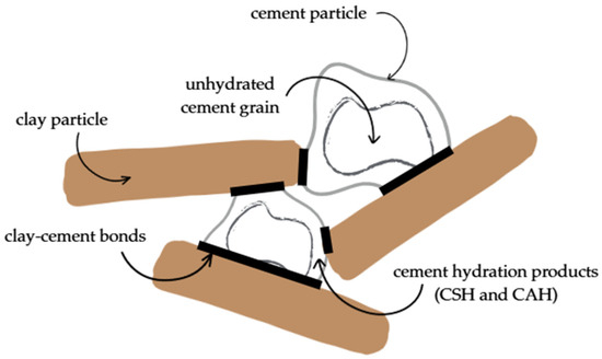
Figure 1.
Soil cementation illustration [44].
2.1. Materials
The soil was obtained from the vicinity of the ‘Fontaines des Gazelles’ (35°07′58.3″ N 5°35′26.2″ E) dam in the Biskra region (Figure 2). Biskra is a province located in northeastern Algeria, forming part of the Saharan Atlas transition zone between the Tell Atlas in the north and the Sahara Desert to the south. The region is characterized by a semi-arid to arid climate with scarce and irregular rainfall, leading to limited surface water resources. Despite this, Biskra plays a vital role in Algerian agriculture due to its extensive use of groundwater for irrigation, especially in palm groves [45].
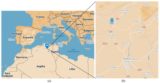
Figure 2.
Location of Biskra (Algeria) in Africa (a) and ‘Fontaines des Gazelles’ dam (b).
Previous research by Belmana et al. (2024) [15] has characterized the soil and the cement used in this investigation, set-up illustration and images are exposed in Figure 3. The granulometric analyses reveal that the grain size distribution curve is primarily composed of 10% clay, 23% silt, 57% sand, and 10% gravel (Figure 4a). The uniformity factor is 187, and the curvature factor is 6.9. According to the French standard AFNOR NF P1992 11-300 [46], it is classed as B5, which means it is a very silty medium gravel. According to French classification [46], the soil has low plasticity and consistency (Ic = 0.69). The clayey fraction of the soil is characterized by its significant clay activity (Ac) of 1.25 and the presence of calcic montmorillonite. XRD and SEM are shown in Figure 4b–e.
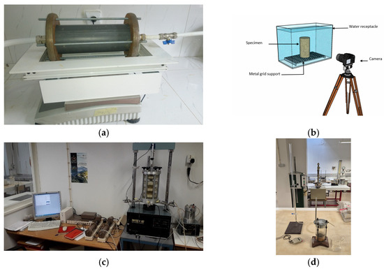
Figure 3.
The erosion cell (a), sketch of the Crumb device (b), triaxial automated system (c), and hydraulic conductivity test (d).
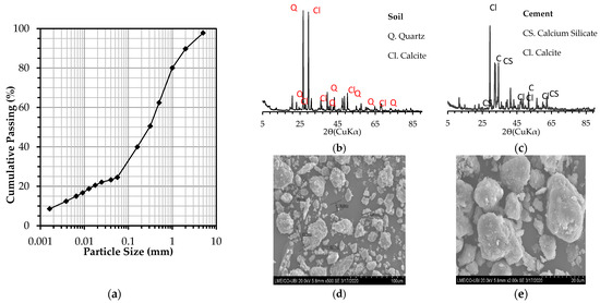
Figure 4.
Particle size distribution of the soil (a), XRD analysis of the soil (b) and the cement (c), SEM images of the soil with ×500 (d) and ×2000 (e) magnifications.
The cement utilized for the treatment is Portland cement, referred to as CEMII/B-L42,5N, supplied by LAFARGE Company. It is approved and meets the standards of both Algerian (NA442–2013) and European (EN197-1) standards [47,48], following a clinker of 63% C3S and 8.5% C3A. The chemical compositions and properties of soil and cement are detailed in Table 1. The mineralogical investigations are conducted using XRD and EDX in addition to granulometric analyses.

Table 1.
Geotechnical and chemical properties of the soil and the cement.
2.2. Specimens Preparation
To prepare the test specimens, the soil was dried in an oven and then mixed using a MATEST 30 L mixer with a power of 1.1 Kw. Subsequently, it is also employed for blending the soil with cement. The soil was prepared in advance by mixing to the optimal moisture content from the Normal Proctor, then sealed in plastic bags for 24 h for homogeneity. The cement treatment preparation followed a 24 h period of storage, then the soil was mixed with a quantity of cement equal to the target dosage (1%, 2%, and 3%) until the soil was visually observed to have a grind whose granularity was stabilized and which had a uniform color. Following this, the soil was once more placed in an airtight bag for a maximum of fifteen minutes prior to the compaction according to the Normal Proctor standard NF P 94-093, using low-energy compaction and standard mold [49].
For HET tests, a cylindrical PVC mold measuring 100 mm in diameter and 200 mm in length was used to prepare the soil specimen (Figure 5b). For triaxial tests, a cylindrical copper mold measuring 70 mm in diameter and 140 mm in length was used to prepare the specimen (Figure 5c). To obtain uniform compaction, the soil specimen was dynamically compacted into three layers of equal thickness inside the PVC mold with a Normal Proctor test hammer. The amount of material and the required mixing water content were calculated from the desired final dry density using the standard Proctor curve (Figure 5a). Figure 5d,e illustrate the storage of HET and triaxial specimens, respectively. The specimens prepared to carry out the two tests (HET, Crumb test) have the same characteristics.
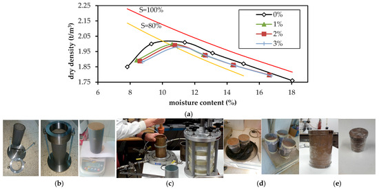
Figure 5.
Normal Proctor compaction curves (a) with saturation lines (S) of 100% (red) and 80% (yellow), HET (b), and triaxial (c) samples’ compaction procedure, and HET (d) and triaxial (e) storage methods.
The characteristics of compacted specimens are summarized in Table 2. The specimens were compacted to 90% of the maximal dry density on the wet side of optimum moisture content, which is considered the most unfavorable case regarding internal erosion stability of the soil [15]. The specimens were then covered with plastic film to prevent water evaporation and to preserve the compaction’s water content, and they were stored at an ambient temperature of roughly 20 °C until the test day.

Table 2.
Compaction characteristics of the specimens.
2.3. Testing Procedures
2.3.1. Hole Erosion Test
A hole Erosion apparatus inspired by the one developed by Wan et Fell [50,51] was used to carry out laboratory tests, and can be considered an efficient tool to assess piping erosion initiation and to characterize the internal erosion of soils. The whole system consists of the following elements: the erosion cell containing the tested sample, the eroded particle collection tank, a tank with constant hydraulic head, with overflow recovery, a water supply tank, and a hydraulic pump.
Additionally, the erosion cell consists of three parts; the first one is an upstream base with an inlet diameter of 30 mm, which ensures a constant inflow for each hydraulic load. The central (second) part is a PVC cylinder of 100 mm in diameter and 250 mm in length; 50 mm of it is reserved to receive gravel, the role of which is to make the inflow homogeneous, and 200 mm for the specimen with a preformed hole, separated by means of a metal grid of 1 mm from the gravel. Downstream, there is another base, and it has an outlet with a 30 mm diameter.
The hole in the specimens was drilled after compaction. The different elements of the device are connected using sections set of tubes fitted with quick couplings and valves, as illustrated in Figure 3a.
2.3.2. Modified Crumb Test
The principle of this test is based on the Crumb Test described in the standard (ASTM D 6572-13) [52]; however, it was adjusted to fit the specimen dimension. The specimens reserved for this test were prepared with the same method as that of the erosion (HET) test. The specimens were deposited on a metal support, allowing for contact with the water below the specimen, and then emerged in a glass tank.
The test consists of immersing a specimen of known density and dimensions in a tank of water and following its morphological evolution over time, and assessing its dispersion in water as it is illustrated in Figure 3b [53]. The whole device comprises a PVC mold measuring 100 × 200 mm, which is used for producing the compaction; a glass tank with a thickness of 0.5 mm and dimensions of 500 × 500 × 500 mm with a practical capacity of 125 L; a metallic grid; and a camera used for capturing and recording visual images.
2.3.3. Triaxial Test
Triaxial tests were performed according to AFNOR (1994) NF 94-074 [54] to study the influence of cement treatment on the mechanical behavior of the soil after compaction; Consolidated Undrained (CU) tests were carried out on untreated and treated specimens in order to evaluate the shear strength evolution of the soil before and after treatment as well as after curing time of 1, 7, 28, and 90 days.
Triaxial tests were conducted under three confining pressures: 200, 300, and 500 kPa. For each curing time, three specimens were tested by confining pressure to determine cohesion (c′) and internal friction angle (φ′) using Mohr–Coulomb fitting. The soil was allowed to consolidate under the confining pressure before loading, but no drainage was allowed during the shearing phase. This test provides valuable information on pore pressure development, and the apparatus is shown in Figure 3c.
2.3.4. Hydraulic Conductivity
The hydraulic conductivity was measured for untreated and cement-stabilized soil. As is shown in Figure 3d, the test process employed was the falling-head method as outlined by Bowles (1978) and the ASTM D2434 standard [55,56]. The permeability coefficient will be determined from the linear segment of the curve using Equation (1) corrected by Equation (2):
where a is the cross sectional area of the piezometric tube (m2), l is the specimen height during the test (m), A is the cross sectional area of the specimen (m2), t is the interval between measurements (s), h1 is piezometric head at the start of the selected interval (m), and h2 is the piezometric head at the end of the selected interval (m). Note that h1 and h2 are measured with reference to the outlet head. The (ηT/η20) is the viscosity correction for the tested water temperature.
2.3.5. Microstructure Analysis
Several techniques were used to analyze the microstructure of the soil before and after treatment to explain the improvements in geotechnical qualities that result from lime/cement interactions. First, scanning electron microscope (SEM) observations at the micro level were performed on both untreated and treated samples after 28 days of curing time, using HITACHI S-3400N (Hitachi, Ltd., Tokyo, Japan).
This was followed by thermogravimetric analysis (TGA), which is a technique that involves measuring changes in weight as temperature increases. The fine soil elements were characterized using the TA Instruments Q50 (TA Instruments, New Castle, PA, USA), to assess changes in physicochemical properties at high temperatures as a function of increasing temperature, both before and after treatment [40]. TGA was conducted on samples weighing 8 ± 0.5 mg. The samples were heated at a rate of 20 °C/min, starting from the ambient temperature and reaching a maximum temperature of 1000 °C. The substance nature will be designated based on the change in weight (%) and the derivative (D.W.) of this latter (%/°C).
Next, the Mercury Intrusion Porosimeter (MIP) technique was adopted to analyze the fabric and porosity of the soil samples using the Micromeritics AutoPore IV 9500 (Micromeritics Instrument Corporation, Norcross, GA, USA) apparatus. This technique enables the determination of a wide range of pore sizes, ranging from a few nanometers to several tens of micrometers, and allows for the identification of different types of soil pores. The principle behind this technique is the intrusion of mercury into a porous structure under carefully controlled pressures, following the capillary law that governs the penetration of liquid into small pores. In the case of a non-wetting liquid like mercury, this law is expressed by the Washburn equation (Equation (3)).
where P is the applied pressure, D is the apparent pore diameter, γ is the surface tension of the mercury, and θ is the contact angle between the mercury and the sample.
3. Results and Analysis
3.1. Previous Characterization
Belmana et al. (2024) [15] conducted a previous characterization of the materials described. Figure 4b,c exposes XRD analyses, which permitted the identification of the essential crystalline phases contained in the materials, and it indicates that the primary crystalline minerals in the soil are quartz (Q) and calcite (Cl). The results showed that the predominant elements present are silica (SiO2), calcium oxide (CaO), and alumina (Al2O3). They also revealed that the primary constituents of the cement were calcite (CaCO3) and quartz (SiO2), due to the use of calcite (CaCO3) and calcium silicate (CS) (Ca3SiO5) in the production of cement. In addition, SEM images of the untreated soil are presented in Figure 4d,e.
3.2. Hole Erosion Test
HET tests were conducted on both untreated and cement-treated coarse soils to assess how varying cement dosages and curing times affect resistance to internal erosion. Tests were performed after 1, 7, and 28 days of curing using different cement contents to determine the optimal conditions for enhancing soil stability against piping.
3.2.1. Eroded Particles Mass
This part delineates and illustrates the initiation and advancement of internal erosion mechanisms in untreated soil, focusing on the most unfavorable scenario outlined by Belmana [15], wherein a horizontal unidirectional flow is induced by elevating the hydraulic head.
Figure 6a shows that untreated soil begins eroding at a low hydraulic gradient of 1, indicating early internal instability. The mass of eroded particles increases with the hydraulic gradient, peaking at 34.6 g at gradient 3. Beyond this, erosion decreases, reaching 5.33 g at gradient 7 and stabilizing around 7.5 g at higher gradients. This reduction is linked to hole enlargement, which lowers water pressure and shear stress, thus reducing particle detachment.
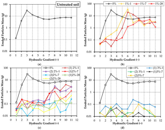
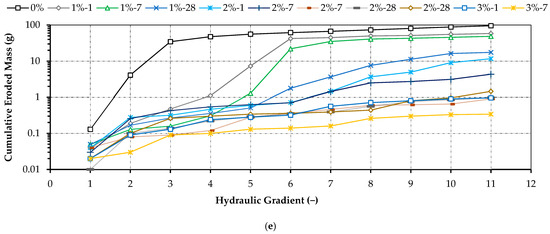
Figure 6.
Evolution of eroded particles and cumulative eroded mass of untreated soil (a) during the charging phase on 1% (b), 2% (c), and 3% (d) cement-treated soil, and the cumulative mass of the eroded particles (soil + cement) (e).
With 1% cement treatment (Figure 6b), erosion starts at a higher gradient (2), suggesting improved stability. The peak mass is 34.93 g at gradient 6 for 1-day cured samples. However, with 7 days of curing, erosion is reduced, and stability improves up to gradient 4. After 28 days, erosion is resisted up to gradient 5, but the soil still shows signs of instability under higher loads.
Figure 6c indicates that 2% cement-treated soils show better resistance than 1% treatments, with the maximum eroded mass being only 4.9 g, even at gradient 10 after 24 h. Despite this improvement, the soil remains vulnerable to erosion, even after 28 days of curing. Figure 6d demonstrates that 3% cement-treated soils achieve the highest stability. After just 24 h and 7 days of curing, erosion is minimal (less than 0.01 g) even under a hydraulic gradient of 11. These results confirm that 3% cement is the optimal dosage.
Figure 6e compares cumulative eroded mass across all conditions. The untreated soil shows the highest cumulative erosion, reaching 95 g by test end. Cement treatment significantly reduces cumulative erosion in proportion to both dosage and curing time. The lowest value recorded was 0.18 g after 7 days of curing with 3% cement, confirming this dosage as the most effective for stabilizing the tested soil.
Particle agglomeration and adhesion necessitate greater shear stresses for detachment from a surface in contact with water flow, hence reducing the erodibility of treated soil relative to untreated soil. The initial effects of incorporating cement primarily induce clay particle flocculation, which may enhance the early strength of the treated samples, subsequently leading to pozzolanic reactions that establish bonds between soil particles and inhibit their separation [27,57]. Consequently, it is essential to exert supplementary hydraulic shear stress to disrupt these connections and facilitate the detachment of smaller agglomerates or individual soil particles.
3.2.2. Outflow
Regarding the untreated soil (Figure 7a), the outflow was at 47 L/h in the beginning of the experiment; then, under the increase in hydraulic loads, the shear stress augments, resulting in particle detachment and consequently in enlargement of the hole diameter, which leads to a larger outflow that ends up at 459 L/h. This ultimately depends on the cumulative eroded particle mass, or weight. In other words, a rise in cumulative eroded particle mass is associated with a greater outflow.
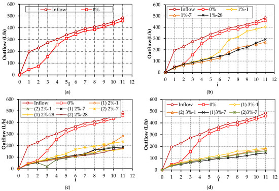
Figure 7.
Evolution of the outflow during the charging phase on untreated soil (a), 1% (b), 2% (c), and 3% (d) cement-treated soil.
Post-treatment, Figure 7b–d indicates a reduction in outflow as a function of the hydraulic gradient, influenced by elevated cement doses and extended curing time. The outflow is dependent on the current diameter of the hole. In the erosion test, the untreated soil experiences substantial particle mass loss; hence, the hole’s diameter progressively enlarges with the increase in hydraulic load, leading to high water outflow. Conversely, the treated soil, due to its enhanced resistance, restricts both particle detachment and outflow. Consequently, as the dosage and treatment duration increase, the outflow progressively diminishes.
3.2.3. Hole’s Final Diameter
The final diameter of the hole, which is derived from the mean diameter of the extracted paraffine and is shown in Figure 8a as (D0) and Figure 8b–e, can also be used to assess the soil’s resistance to piping erosion. Figure 8b,c shows that the final diameter of the untreated soil is 16 mm. This diameter decreases as the dosage of cement is increased and the curing time is extended, reaching a low value of 4.04 mm (Figure 8d,e), which corresponds to the case of soil treated with 3% cement after 7 days. Additional photographs depicting the final diameter and configuration of the extracted paraffin are presented below in Figure 8f–h.
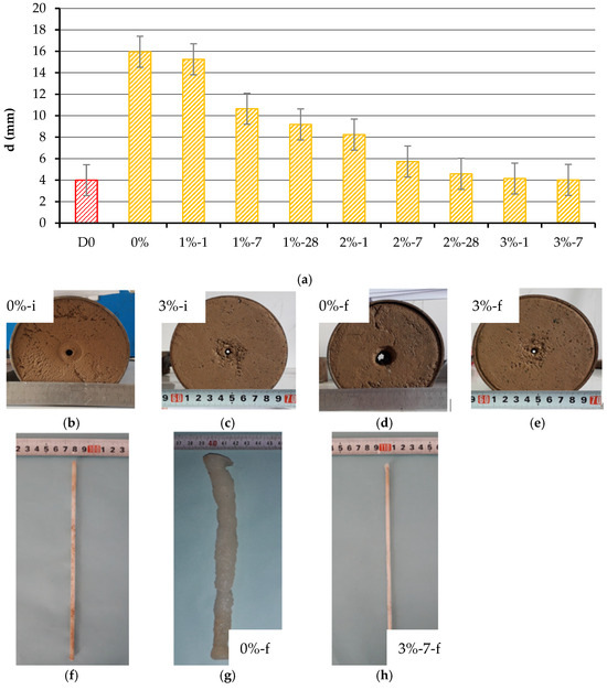
Figure 8.
Evolution of the final hole diameter size compared with the initial one (a), initial and final hole diameter of untreated soil (b) and 3% (c) cement-treated soil before test, and after test for untreated soil (d), and 3% cement-treated soil (e), in addition to the shape of extracted paraffin before test (f), after test for untreated soil (g), and after test for 3% 7 days cement-treated soil (h).
3.3. Modified Crumb Test
The immerged specimen created with untreated soil withstands only 7 h until the full collapse (Figure 9a). It should be emphasized that the detachment of the particles from the solid mass began from the first minutes of the specimen being immersed in water. After approximately one hour of immersion, the disintegration of larger flocs was noted, devoid of the turbidity effect characterized by a halo of suspended particles surrounding the sample, in contrast to the experiments conducted by Elandaloussi [58]; however, this effect was observed after five hours, when the specimen was fully dispersed.
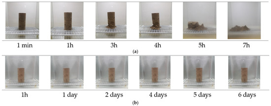
Figure 9.
Shape of immerged sample for untreated soil (a), and 3% cement-treated soil (b).
Conversely, the samples treated with 3% cement remain manifestly unflawed after only 24 h of curing, maintaining their original form throughout 6 days of immersion (Figure 9b), with minimal, if any, detachment of agglomerate mass. This corroborates the findings regarding the treated soil’s resistance to erosion.
The results indicate the treatment’s effectiveness after one day, demonstrating the mitigation of the soil’s dispersive nature and its erosion susceptibility, thereby confirming that initial chemical reactions were responsible for reducing erosion at a short curing duration.
3.4. Triaxial Test
Triaxial tests assess the improvement in mechanical properties of compacted soil before and after cement treatment, offering insight into the effects of cement on soil strength behavior on the mechanical characteristics. The subsequent results were derived from consolidated undrained (CU) tests conducted within the normally consolidated domain on both natural soil and soil treated with 3% cement.
This 3% cement content was identified as optimal for effective soil stabilization against erosion. The mechanical enhancement resulting from this treatment was then evaluated. Figure 10a depicts specimens subjected to the triaxial test for untreated soil, while Figure 10b illustrates specimens subjected to the triaxial test for soil treated with 3% cement, respectively, after 90 days of curing, where a visible shear plane indicates failure behavior.

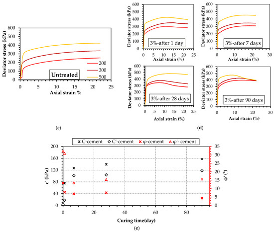
Figure 10.
Untreated specimen (a) and 3%-90 days (b) after test, deviator stress versus axial strain for untreated soil (c) and 3% treated soil for 1–90 days of curing (d), and the evolution of cohesion and friction angle versus curing time (e).
When comparing the treated specimens to the untreated ones, Figure 10c,d reveals that deviator stress increases with both confinement stress and curing time, resulting in enhanced shear strength of the soil. The deviator stress values recorded for specimens cured for seven days surpass those reported by Sariosseiri and Muhunthan [38] for specimens treated with 5% cement.
The parameters of untreated soil were determined as c’ = 3.23 kPa for effective cohesion and φ’ = 32.26° for the friction angle (Figure 8e). The friction angle decreases to 30.93° after 24 h of cement treatment; on the 7th day, it drops to 13.48° and stabilizes around 15° after 28 days of curing. Simultaneously, the soil attains an additional cohesiveness of 17.81 kPa after 24 h, with considerable increases in cohesion reaching 101.33, 103.75, and 117.79 kPa on the 7th, 28th, and 90th days of curing, respectively. The c’ increased by a factor of 31 compared to untreated soil.
Cement hydration rapidly produces calcium hydroxide and elevates pH, creating an alkaline environment. Subsequently, pozzolanic reactions occur between calcium hydroxide, siliceous and aluminous components from clays, and water.
This process results in a new configuration of soil particles due to the formation of cohesive bonds, which arise from the cementitious connections between calcium silicate hydrate (C-S-H) and calcium aluminate hydrate (C-A-H). Consequently, cohesion increases over curing time, leading to a heightened threshold for shear stress resistance. These findings are confirmed by the TGA analysis presented in the subsequent section [59,60].
The significant improvement in shear strength is attributed to the development of internal cementitious bonding, leading to better cohesion [27]. The soil’s enhanced stability shows the beneficial effects of cement addition, which can effectively stabilize and reinforce a dispersed soil by stimulating flocculation in the short term and through its pozzolanic properties in the long term [25].
3.5. Microstructure Analysis
3.5.1. Thermogravimetric Analysis
The TGA curves for natural and treated soil after 28 days are illustrated in Figure 11, depicting the variation in weight and its derivative (D.W.) versus the temperature change. From ambient temperature to 100 °C, the weight loss indicated by the peak in the D.W. curve corresponds to moisture loss. A peak is noted in the temperature range of 115–150 °C, signifying the presence and decomposition of calcium silicate hydrate (CSH) and calcium aluminate hydrate (CAH) [61,62].
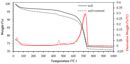
Figure 11.
TG and DTG curves of soil and soil + cement.
These changes reflect the preliminary formation of gelatinous products and their later reconfiguration into crystalline minerals. The 410 °C peak indicates the dihydroxylation of calcium hydroxide (Ca(OH)2), whereas the temperature range from 700 to 750 °C signifies the decomposition of products resulting from the carbonation of Ca(OH)2. The minimal peaks between 450 and 550 correspond to the dehydration of clay minerals and the gelatinous hydration products [63,64].
The weight loss rate between 650 and 750 °C is important. This indicates the abundant presence of calcite, CaCO3, in the soil. Matschei et al. [65] disclosed that most, if not all, of this calcite is reactive and controls the lime distribution, alumina, and sulfate, thereby altering the hydration products’ mineralogy. Thus, two main functions are attributed to calcite: the first as an active participant in the hydration process, which may explain the optimum stabilization of soil with the addition of low lime or cement content, and the second as an inert filler.
3.5.2. Scanning Electron Microscopy
The SEM examinations of both natural as well as stabilized soil are presented in Figure 12. It demonstrates that they are dissimilar in their microstructure morphology. At lower magnification (Figure 12a), untreated soil shows a group of agglomerates of different configurations and sizes, from a few hundred microns to a millimeter. A few numbers of macrospores (inter-aggregate) pores are observed between the agglomerates, resulting from compaction [66]. At a higher magnification (Figure 12b), a tidy association is clearly visible between clay and quartz particles; clay particles form a film that covers the sand grains and connects them tightly. Pores around 0.020 mm can be observed.
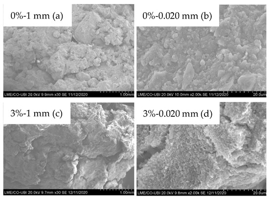
Figure 12.
SEM images of the untreated soil at 1 mm (a) and 0.020 mm (b), and cement-treated soil at 1 mm (c) and 0.020 mm (d).
Upon a low magnification observation of the cement-stabilized specimen (Figure 12c), the soil texture is found to be tighter compared with that of the untreated one. A number of pores of around 10 μm can be observed. At high magnification (Figure 12d), the pictures show a gel enveloping the agglomerates. EDX analysis of this gel confirms the presence of silicon, calcium, and aluminum, which constitute the C-(A)-S-H molecule. Featuring micropores approximately 0.1 m in size.
3.5.3. Mercury Intrusion Porosity
The MIP tests were conducted on both natural and treated samples across various curing durations. The findings are depicted in Figure 13. The differential mercury intrusion curves presented in Figure 13a demonstrate a trimodal pore size distribution for both untreated and treated soil, comprising a small pore class below 0.9 μm, a medium pore class ranging from 0.9 μm to 10 μm, and a large pore class exceeding 10 μm. According to [65], the small pore diameter class is attributed to intra-agglomerate micropores, while the other classes correspond to inter-agglomerate macropores.
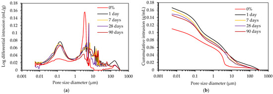
Figure 13.
Evolution of the pore size diameter in MIP for the log differential intrusion (a) and the cumulative intrusion (b).
The untreated soil exhibits a predominant pore size family of approximately 3 μm, which governs permeability alongside macropores. The treatment led to a notable increase in the volume of small pores, which progressively decreases with extended curing time due to the deposition of secondary compounds. Nonetheless, the quantity of medium pores diminishes, with the peak shifting to around 6 μm and disappearing after 90 days, which correlates with the development of gelatinous and crystalline hydration products. Furthermore, there is a minor increase in the large pores class on the first day of treatment; however, this amount diminishes over the curing period, returning to levels comparable to untreated soil due to the filling of pores by hydration products.
The cumulative mercury intrusion curves, depicted as a function of pore size diameter in Figure 13b, indicate that, on the first day of curing, the pore volume increases, particularly pronounced in the pore range below 0.9 μm, thereby confirming the variation in dry density following cement incorporation. The volume diminishes gradually over the course of the cure.
3.6. Hydraulic Conductivity
The hydraulic conductivity plots for natural and stabilized soil with cement are shown in Figure 14. The untreated soil shows an extremely low permeability coefficient. Following cement treatment, the permeability coefficient exhibited a slight increase; however, it remained comparable to that of the untreated sample.
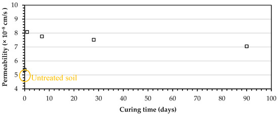
Figure 14.
Hydraulic conductivity of the untreated soil.
Initially, after 24 h of treatment, the hydraulic conductivity values for the stabilized soil are a little higher than untreated soil but decrease over the curing time. This is attributed to the development of a new category of pores due to the hydration of cement, which is supported by the MIP results presented previously, as well as the pozzolanic reactions of cement addition at later ages. Stocker [67] reported that only 0.5% Ca(OH)2 is sufficient to produce a unit layer of reaction product and eliminate swelling. Subsequently, the process becomes diffusion-dependent, as Ca2+ ions must diffuse through the reaction product. As the solubility of calcium hydroxide is low, either formed due to the hydration of Portland cement or supplied by the hydrated lime, Stocker’s observation suggests that, by increasing the stabilizer dosage, the gain in the long-term properties may not be significantly different.
4. Discussion
The experimental findings confirm the potential of cement treatment to enhance the geomechanical behavior of coarse soils used in embankment applications. The treated samples increased in UCS, reduced porosity, and improved resistance to internal erosion mechanisms. These improvements are primarily attributed to the cement hydration process, which promotes the development of a denser, interlocked matrix through the formation of calcium silicate hydrates and other pozzolanic reaction products. It seems important to enlarge the discussion on the impact of cemented soils technologies, the durability and scalability challenges, and the alternative materials to address geoenvironmental sustainability.
4.1. Cemented Soils
The exposed behavior is consistent with previous findings in the literature, where studies identified key parameters such as porosity–cement ratio and particle arrangement as critical in controlling strength in artificially cemented sandy soils [68]. In addition, the evolution of UCS with an increasing cement content and curing time, shown in several places worldwide [69], validates the specific context of Biskra’s dam soil.
Nonetheless, the performance of cement-stabilized soils is not only governed by the amount of binder or curing conditions. Particle size distribution and mineralogical composition also play a significant role in cementation. Many authors have analyzed different soil classifications and their effect in cementing processes, like expansive [70], clays [71], bentonites [72], organic silts [73], sands [74], and coarse soils [75].
4.2. Embankment Scalability and Durability
While cementation improves mechanical strength and erosion resistance, embankment durability under varying environmental and loading conditions requires further performance enhancements. Laboratory-scale experiments provide essential insight into fundamental behavior; however, field-scale validation confirms the real-world [76,77]. Embankment-scale heterogeneity, variable compaction levels, and environmental exposure often result in performance deviations that cannot be controlled in laboratory settings [78]. The current study would benefit from a transition toward pilot-scale testing or field application.
In this context, the use of fiber reinforcement has gained significant attention; both synthetic (e.g., polypropylene and polyester [79]) and natural (e.g., coir and jute [80]) have been shown to improve ductility, crack resistance, and post-peak behavior of treated soils [81]. Randomly distributed fibers delay crack propagation and enhance strain capacity, making cemented soils more suitable for cyclic or dynamic loading conditions [82]. Future investigations should, therefore, consider integrating fibers into the cement–soil matrix studied here, assessing their effect on long-term degradation, particularly under wet–dry or freeze–thaw cycles that often compromise conventional cemented structures.
4.3. Geoenvironmental Alternative Materials
The environmental footprint of Portland cement production still corroborates for alternative binders’ production due to the advantage of reusing some industrial by-products and reducing CO2 emissions [83]. The already traditional alternatives are lime, fly ash, slags, cement kiln dust, and, more recently, alkali-activated binders, which provide adequate strength and durability [84].
The current search for environmental techniques and recycling processes has led to the investigation of more alternatives for cementitious and ceramsite geocomposites. For example, studies have reutilized rice husk, sugarcane, municipal solid waste, and volcanic ashes, metallurgical slags, red mud, water treatment and sewage sludge, and paper slurry as binders, in addition to aggregate substitution within glass ash, seashells, e-wastes, and natural and plant-based fibers [85]. Recent advances in geotechnical engineering, including digital geomechanics and real-time performance monitoring, can be integrated into long-term leaching evolution and contribute to resistance to chemical attack.
5. Conclusions
This study aims to assess the hydraulic, mechanical, and microstructural characteristics of the soil before and after cement treatment, along with its applicability in hydraulic earthworks. The results indicated that the natural soil exhibited instability concerning internal erosion, and the findings achieved an optimal cement dosage of 3% by dry weight and a curing time of 7 days. The results are quite low compared to other research, which is especially appealing from an economic standpoint regarding cost reduction for the project.
Crumb tests highlighted the contribution of cement addition in the annulation of soil’s dispersive character in water after only 24 h due to the flocculation of the soil particles. Moreover, the gain in mechanical strength post-treatment was significant and proportional to curing time, which explains the stability of the treated soil towards internal erosion in the HET tests due to the enhanced cohesion between the soil particles. Microstructure results revealed that the enhancement obtained after cement addition seems to be the consequence of a couple of physicochemical interactions, resulting in the formation of a new configuration of agglomerates at first, followed by the precipitation of hydrated compounds. Furthermore, the chemical composition of Biskra’s soil provided an appropriate medium for the pozzolanic reactions. The hydraulic conductivity of stabilized soil is slightly higher than natural soil at all curing times. The results obtained are attributed to the formation of a new category of pores because of the hydration of cement and the pozzolanic reaction products over the curing period.
Thus, the optimal cement content was determined for the specific locally extracted coarse soils in the Biskra region, deemed waste due to their poor hydraulic and mechanical properties. The limitations of this study indicate that future investigations into the behavior of compacted coarse soils should be conducted using soils with different hydrogeological backgrounds, particle size distributions, and mineralogy compositions, and more extensive datasets would allow for statistical correlation, in addition to field compaction variability and investigations into the influence of different water chemistry to simulate sulfate-rich and contaminated environments, the transport of contaminants, and the impact of cyclic loading.
Author Contributions
Conceptualization, A.B. and V.C.; methodology, A.B., M.M. and V.C.; validation, L.A.P., H.A.S.P., V.G., A.S., M.V.M. and L.M.; investigation, A.B. and V.C.; resources, V.C. and L.M.; data curation, A.B. and V.C.; writing—original draft preparation, A.B. and L.M.; writing—review and editing, V.C., M.M., L.A.P., H.A.S.P., V.G., A.S. and M.V.M.; supervision, V.C. and M.M. All authors have read and agreed to the published version of the manuscript.
Funding
This research received no external funding.
Data Availability Statement
The original contributions presented in this study are included in the article. Further inquiries can be directed to the corresponding author.
Acknowledgments
This work was supported by the GeoBioTec Research Unit, through the strategic projects UIDB/04035/2020 (https://doi.org/10.54499/UIDB/04035/2020 accessed on 1 January 2025) and UIDP/04035/2020 (https://doi.org/10.54499/UIDP/04035/2020 accessed on 1 January 2025), funded by the Fundação para a Ciência e a Tecnologia, IP/MCTES through national funds (IDDAC).
Conflicts of Interest
The authors declare no conflicts of interest.
Abbreviations
The following abbreviations are used in this manuscript:
| HET | Hole erosion test |
| SEM | Scanning electron microscope |
| TGA | Thermogravimetric analysis |
| MIP | Mercury intrusion porosimetry |
| XRD | X-ray diffraction analysis |
| EDX | Energy-dispersive X-ray analysis |
References
- Talukdar, P.; Dey, A. Hydraulic failures of earthen dams and embankments. Innov. Infrastruct. Solut. 2019, 4, 42. [Google Scholar] [CrossRef]
- Powledge, G.R.; Ralston, D.C.; Miller, P.; Chen, Y.H.; Clopper, P.E.; Temple, D.M. Mechanics of overflow erosion on embankments. II: Hydraulic and design considerations. J. Hydraul. Eng. 1989, 115, 1056–1075. [Google Scholar] [CrossRef]
- Johnston, I.; Murphy, W.; Holden, J. A review of floodwater impacts on the stability of transportation embankments. Earth-Sci. Rev. 2021, 215, 103553. [Google Scholar] [CrossRef]
- Bonelli, S. (Ed.) Erosion in Geomechanics Applied to Dams and Levees; John Wiley & Sons: Hoboken, NJ, USA, 2013. [Google Scholar]
- Certini, G.; Scalenghe, R.; Woods, W.I. The impact of warfare on the soil environment. Earth-Sci. Rev. 2013, 127, 1–15. [Google Scholar] [CrossRef]
- Hore, S.; Alim, M.A.; Hore, R. Impact of Earthquakes on Soil Chemical Properties: A Review of Mechanisms, Changes, and Implications for Environmental and Structural Resilience. Earthquake 2025, 3, 1. [Google Scholar] [CrossRef]
- Bonelli, S. (Ed.) Erosion of Geomaterials; John Wiley & Sons: Hoboken, NJ, USA, 2012. [Google Scholar]
- Dunne, T. Hydrology mechanics, and geomorphic implications of erosion by subsurface flow. In Groundwater Geomorphology:The Role of Subsurface Water in Earth-Surface Processes and Landforms; Geological Society of America: Boulder, CO, USA, 1990; Volume 252. [Google Scholar] [CrossRef]
- Umar, I.H.; Abubakar, A.; Salisu, I.M.A.; Lin, H.; Hassan, J.I. Geotechnical Stability Analysis of the Tiga Dam, Nigeria on the Assessment of Downstream Soil Properties, Erosion Risk, and Seasonal Expansion. Appl. Sci. 2024, 14, 56422. [Google Scholar] [CrossRef]
- Yao, Y.; Fan, J.; Li, J. A Review of Advanced Soil Moisture Monitoring Techniques for Slope Stability Assessment. Water 2025, 17, 390. [Google Scholar] [CrossRef]
- Nciizah, A.D.; Wakindiki, I.I. Physical indicators of soil erosion, aggregate stability and erodibility. Arch. Agron. Soil Sci. 2015, 61, 827–842. [Google Scholar] [CrossRef]
- Ghosh, A.; Manna, M.C.; Jha, S.; Singh, A.K.; Misra, S.; Srivastava, R.C.; Singh, S.P. Impact of soil-water contaminants on tropical agriculture, animal and societal environment. Adv. Agron. 2022, 176, 209–274. [Google Scholar] [CrossRef]
- Roshan, M.J.; Rashid, A.S.B.A. Geotechnical characteristics of cement stabilized soils from various aspects: A comprehensive review. Arab. J. Geosci. 2024, 17, 1. [Google Scholar] [CrossRef]
- Pongsivasathit, S.; Horpibulsuk, S.; Piyaphipat, S. Assessment of mechanical properties of cement stabilized soils. Case Stud. Constr. Mater. 2019, 11, e00301. [Google Scholar] [CrossRef]
- Belmana, A.; Mellas, M.; Cavaleiro, V. Assessment of coarse soil’s stability towards internal erosion: Case of Biskra’s dam soil. Civ. Environ. Eng. 2024, 20, 332–348. [Google Scholar] [CrossRef]
- Ghadakpour, M.; Choobbasti, A.J.; Kutanaei, S.S. Experimental study of impact of cement treatment on the shear behavior of loess and clay. Arab. J. Geosci. 2020, 13, 184. [Google Scholar] [CrossRef]
- Croft, J.B. The influence of soil mineralogical composition on cement stabilization. Geotechnique 1967, 17, 119–135. [Google Scholar] [CrossRef]
- Millogo, Y.; Morel, J.C. Microstructural characterization and mechanical properties of cement stabilised adobes. Mater. Struct. 2012, 45, 1311–1318. [Google Scholar] [CrossRef]
- Osula, D.O.A. A comparative evaluation of cement and lime modification of laterite. Eng. Geol. 1996, 42, 71–81. [Google Scholar] [CrossRef]
- Khemissa, M.; Mahamedi, A. Cement and lime mixture stabilization of an expansive overconsolidated clay. Appl. Clay Sci. 2014, 95, 104–110. [Google Scholar] [CrossRef]
- Bhattacharja, S.; Bhatty, J. Comparative Performance of Portland Cement and Lime Stabilization of Moderate to High Plasticity Clay Soils. Portl. Cem. Assoc. 2003, 2066, 60–67. Available online: www.cement.org (accessed on 25 January 2025).
- Jafer, H.M.; Atherton, W.; Ruddock, F.; Loffil, E. Comparative Study of the Performance of Ordinary Portland Cement and a Waste Material in Soft Soil Stabilisation. Available online: https://www.researchgate.net/publication/301684397 (accessed on 25 January 2025).
- Al-Rawas, A.A.; Hago, A.W.; Al-Sarmi, H. Effect of lime, cement and Sarooj (artificial pozzolan) on the swelling potential of an expansive soil from Oman. Build. Environ. 2005, 40, 681–687. [Google Scholar] [CrossRef]
- Eid, J.; Taibi, S.; Lefebvre, A.; Dandjinou, J.E. Le Traitement des sols à la Chaux et aux Liants Hydrauliques—Aspects Physico-chimiques. In Rencontres Universitaires de Génie Civil, Gradignan, France; 2015; Available online: https://hal.science/hal-01167621/ (accessed on 25 January 2025).
- Jauberthie, R.; Rendell, F.; Rangeard, D.; Molez, L. Stabilisation of estuarine silt with lime and/or cement. Appl. Clay Sci. 2010, 50, 395–400. [Google Scholar] [CrossRef]
- Saussaye, L.; Boutouil, M.; Baraud, F.; Leleyter, L. Soils Treatment with Hydraulic Binders: Physicochemical and Geotechnical Aspects. 2012. Available online: https://www.researchgate.net/publication/260122864 (accessed on 25 January 2025).
- Lemaire, K.; Deneele, D.; Bonnet, S.; Legret, M. Effects of lime and cement treatment on the physicochemical, microstructural and mechanical characteristics of a plastic silt. Eng. Geol. 2013, 166, 255–261. [Google Scholar] [CrossRef]
- Eskisar, T. Influence of cement treatment on unconfined compressive strength and compressibility of lean clay with medium plasticity. Arab. J. Sci. Eng. 2015, 40, 763–772. [Google Scholar] [CrossRef]
- Consoli, N.C.; Foppa, D.; Festugato, L.; Heineck, K.S. Key parameters for strength control of artificially cemented soils. J. Geotech. Geoenviron. Eng. 2007, 133, 197–205. [Google Scholar] [CrossRef]
- Consoli, N.C.; Cruz, R.C.; Floss, M.F.; Festugato, L. Parameters controlling tensile and compressive strength of artificially cemented sand. J. Geotech. Geoenviron. Eng. 2010, 136, 759–763. [Google Scholar] [CrossRef]
- Bellezza, I.; Fratalocchi, E. Effectiveness of cement on hydraulic conductivity of compacted soil–cement mixtures. Proc. Inst. Civ. Eng.-Ground Improv. 2006, 10, 77–90. [Google Scholar] [CrossRef]
- Melbouci, B. Étude comparative du traitement du sol marneux à la chaux et au ciment dans les couches de forme des chaussées. Commun. Sci. Technol. 2017, 18, 79–98. Available online: https://www.researchgate.net/publication/316514778 (accessed on 25 January 2025).
- Rekik, B.; Boutouil, M.; Pantet, A. Geotechnical properties of cement treated sediment: Influence of the organic matter and cement contents. Int. J. Geotech. Eng. 2009, 3, 205–214. [Google Scholar] [CrossRef]
- Al-Amoudi, O.S.B. Characterization and chemical stabilization of Al-Qurayyah sabkha soil. J. Mater. Civ. Eng. 2002, 14, 478–484. [Google Scholar] [CrossRef]
- Ranaivomanana, H.; Razakamanantsoa, A. Toward a better understanding of the effects of cement treatment on microstructure and hydraulic properties of compacted soils. In MATBUD’2018; EDP Sciences: Les Ulis, France, 2018; Volume 163, 8p. [Google Scholar] [CrossRef]
- Nussbaum, P.J.; Colley, B.E. Dam Construction and Facing with Soil-Cement; Portland Cement Association: Skokie, IL, USA, 1971. [Google Scholar]
- Mehenni, A.; Cuisinier, O.; Masrouri, F. Impact of lime, cement, and clay treatments on the internal erosion of compacted soils. J. Mater. Civ. Eng. 2016, 28, 04016071. [Google Scholar] [CrossRef]
- Sariosseiri, F.; Muhunthan, B. Effect of cement treatment on geotechnical properties of some Washington State soils. Eng. Geol. 2009, 104, 119–125. [Google Scholar] [CrossRef]
- Currin, D.D.; Allen, J.J.; Little, D.N. Validation of Soil Stabilization Index System with Manual Development; Frank J. Seiler Researcher Laboratory, USAF Academy: Colorado Springs, CO, USA, 1976. [Google Scholar]
- Catton, M.D. Research on the physical relations of soil & soil mechanics. Highw. Res. Board Bull. 1940, 23, 831–855. [Google Scholar]
- Wooltorton, F.L.D. Engineering pedology and soil stabilization. Highw. Res. Board Bull. 1955, 108, 29–57. [Google Scholar]
- Handy, R.L.; Davidson, D.T. On the curious resemblance between fly ash and meteoritic dust. Proc. Iowa Acad. Sci. 1953, 60, 373–379. [Google Scholar]
- Pakbaz, M.S.; Alipour, R. Influence of cement addition on the geotechnical properties of an Iranian clay. Appl. Clay Sci. 2012, 67, 1–4. [Google Scholar] [CrossRef]
- Halsted, G.E.; Adaska, W.S.; McConnell, W.T. Guide to Cement-Modified Soil (CMS); Portland Cement Association: Stokie, IL, USA, 2008; Available online: https://secement.org/wp-content/uploads/2017/04/EB242.pdf (accessed on 25 January 2025).
- Ratiat, A.; Khettal, T.; Meddi, M. The piezometric and isotopic analysis of leaks in earth dams: The case of the fountain of Gazelle dam, Biskra, Algeria. Environ. Earth Sci. 2020, 79, 138. [Google Scholar] [CrossRef]
- NF P 11-300; Exécution des Terrassements: Classification des Matériaux Utilisables dans la Construction des Remblais et des Couches de Forme D’infrastructures Routières. AFNOR: Saint-Denis, France, 1992.
- NA442; Ciment—Composition, Spécification et Critères de Conformité des Ciments Courants. Institut Algérien de Normalisation: Alger, Algeria, 2013.
- EN197-1; Cement—Composition, Specifications and Conformity Criteria for Common Cements. European Committee for Standardization: Brussels, Belgium, 2011.
- NF P 94-093; Sols: Reconnaissance et Essais Détermination des Références de Compactage d’un Matériau. Essai Proctor Normal—Essai Proctor Modifié. AFNOR: Saint-Denis, France, 1994.
- Volk, G.M. Method of Determination of the Degree of Dispersion of the Clay Fraction of Soils. Proc. Soil Sci. Soc. Am. 1937, 1, 432–445. [Google Scholar]
- ASTM D4647; Standard Test Method for Identification and Classification of Dispersive Clay Soils by the Pinhole Test. ASTM: West Conshohocken, PA, USA, 2006.
- ASTM D6572-13; Standard Test Methods for Determining Dispersive Characteristics of Clayey Soils by the Crumb Test. ASTM: West Conshohocken, PA, USA, 2013.
- NF P 94-074; Sols: Reconnaissance et Essais. Essais à L’appareil Triaxial de Révolution. AFNOR: Saint-Denis, France, 1994.
- Bowles, E.J. Engineering Properties of Soils and Their Measurements, 2nd ed.; McGraw-Hill: New York, NY, USA, 1978. [Google Scholar]
- ASTM D2434-94; Standard Test Method for Permeability of Granular Soils (Constant Head). ASTM: West Conshohocken, PA, USA, 2000.
- Coats, A.W.; Redfern, J.P. Thermogravimetric analysis: A review. Analyst 1963, 88, 906–924. [Google Scholar] [CrossRef]
- Indraratna, B.; Nutalaya, P.; Kuganenthira, N. Stabilization of a dispersive soil by blending with fly ash. Q. J. Eng. Geol. Hydrogeol. 1991, 24, 275–290. [Google Scholar] [CrossRef]
- Elandaloussi, R. Étude du Renforcement/Confortement des Ouvrages de Protection Contre les Inondations et L’érosion Interne. Ph.D. Thesis, Université Paris-Est, Créteil, France, 2015. [Google Scholar]
- Yi, Y.; Gu, L.; Liu, S. Microstructural and mechanical properties of marine soft clay stabilized by lime-activated ground granulated blastfurnace slag. Appl. Clay Sci. 2015, 103, 71–76. [Google Scholar] [CrossRef]
- Sharma, A.K.; Sivapullaiah, P.V. Ground granulated blast furnace slag amended fly ash as an expansive soil stabilizer. Soils Found. 2016, 56, 205–212. [Google Scholar] [CrossRef]
- Sharma, N.K.; Swain, S.K.; Sahoo, U.C. Stabilization of a clayey soil with fly ash and lime: A micro level investigation. Geotech. Geol. Eng. 2012, 30, 1197–1205. [Google Scholar] [CrossRef]
- Peethamparan, S.; Olek, J.; Diamond, S. Mechanism of stabilization of Na-montmorillonite clay with cement kiln dust. Cem. Concr. Res. 2009, 39, 580–589. [Google Scholar] [CrossRef]
- Kolias, S.; Kasselouri-Rigopoulou, V.; Karahalios, A. Stabilisation of clayey soils with high calcium fly ash and cement. Cem. Concr. Compos. 2005, 27, 301–313. [Google Scholar] [CrossRef]
- MacPhee, D.E.; Black, C.J.; Taylor, A.H. Cements incorporating brown coal fly ash from the Latrobe Valley region of Victoria, Australia. Cem. Concr. Res. 1993, 23, 507–517. [Google Scholar] [CrossRef]
- Matschei, T.; Lothenbach, B.; Glasser, F.P. The role of calcium carbonate in cement hydration. Cem. Concr. Res. 2007, 37, 551–558. [Google Scholar] [CrossRef]
- Nguyen, T.T.H. Stabilisation des Sols Traités à la Chaux et Leur Comportement au Gel. Ph.D. Thesis, Université Paris-Est, Créteil, France, 2015. [Google Scholar]
- Stocker, P.T. Diffusion and diffuse cementation in lime and cement stabilised clayey soils chemical aspects. Aust. Road Res. 1972, 5, 6–47. [Google Scholar]
- Fan, J.; Wang, D.; Qian, D. Soil-cement mixture properties and design considerations for reinforced excavation. J. Rock Mech. Geotech. Eng. 2018, 10, 791–797. [Google Scholar] [CrossRef]
- Axel, M.; Li, X.; Wen, F.; An, M.-X. Microstructure and Strength Parameters of Cement-Stabilized Loess. Geotechnics 2023, 3, 161–178. [Google Scholar] [CrossRef]
- Chabrat, N.; Cuisinier, O.; Masrouri, F. In Situ Alteration of the Hydro-Mechanical Behaviour of a Compacted Stabilised Expansive Soil. Geotechnics 2023, 3, 921–936. [Google Scholar] [CrossRef]
- Abdallah, A.; Russo, G.; Cuisinier, O. Statistical and Predictive Analyses of the Strength Development of a Cement-Treated Clayey Soil. Geotechnics 2023, 3, 465–479. [Google Scholar] [CrossRef]
- Alzayani, N.J.; Royal, A.C.; Ghataora, G.S.; Jefferson, I. Cement-bentonite in comparison with other cemented materials. Environ. Geotech. 2017, 4, 353–372. [Google Scholar] [CrossRef]
- Zhu, J.F.; Tao, Y.L.; Xu, R.Q.; Yang, H.; Pan, B.J. Investigation on the optimal formulation and mechanism of marine organic silt improved with magnesium-cement-based stabilizer. Constr. Build. Mater. 2022, 341, 127233. [Google Scholar] [CrossRef]
- Petchgate, W.; Pongsivasathit, S.; Tangpagasit, J.; Piyaphipat, S.; Pinpatthanapong, K.; Thongindam, P. Sustainable soil stabilization: Evaluating the feasibility of hydraulic cement in the deep mixing method. Case Stud. Constr. Mater. 2025, 22, e04394. [Google Scholar] [CrossRef]
- Li, J.; Qian, J.; He, C. Experimental analysis of cement-treated red sandstone coarse-grained soil and its microstructural evolution. Case Stud. Constr. Mater. 2022, 17, e01535. [Google Scholar] [CrossRef]
- Tota-Maharaj, K.; Madushani, S.S.; Monrose, J.; Rathnayake, U. Diagnosis of Low-Carbon Permeable Pavements: Bearing Capacity and Long-Term Clogging Behaviour. Int. J. Pavement Res. Technol. 2025. [Google Scholar] [CrossRef]
- Al-Hadidi, M.T.; Al-Maamori, Z.H.N. Improvement of Earth Canals Constructed on Gypseous Soil by Soil Cement Mixture. J. Eng. 2019, 25, 23–37. [Google Scholar] [CrossRef][Green Version]
- Prakash, K.G.; Krishnamoorthy, A. Stability of Embankment Constructed on Soft Soil Treated with Soil–Cement Columns. Transp. Infrastruct. Geotech. 2023, 10, 595–615. [Google Scholar] [CrossRef]
- Fode, T.A.; Jande, Y.A.C.; Kivevele, T. Physical, mechanical, and durability properties of concrete containing different waste synthetic fibers for green environment—A critical review. Heliyon 2024, 10, e32950. [Google Scholar] [CrossRef]
- Singh, A.; Yadav, B.P. Sustainable innovations and future prospects in construction material: A review on natural fiber-reinforced cement composites. Environ. Sci. Pollut. Res. 2024, 31, 62549–62587. [Google Scholar] [CrossRef]
- Zhang, J.; Xu, W.; Gao, P.; Yao, Z.; Su, L.; Qiu, N.; Huang, W. Compressive strength characteristics of hybrid fiber-reinforced cemented soil. Int. J. Pavement Eng. 2022, 24, 2104843. [Google Scholar] [CrossRef]
- Wang, H.; Cheng, Q.; Zhou, N.; Su, H.; Yin, Q.; Du, B.; Zhang, L.; Yao, Y. An Experimental Study on the Mechanical Properties and Microstructure of the Cemented Paste Backfill Made by Coal-Based Solid Wastes and Nanocomposite Fibers under Dry–Wet Cycling. Materials 2024, 17, 2256. [Google Scholar] [CrossRef] [PubMed]
- Danieli, S.; Neto, J.S.A.; Soares, E.G.; Oliveira, T.F.; Brito, B.L.; Kirchheim, A.P. Shaping a Sustainable Path: Exploring Opportunities and Challenges in Carbon Capture and Utilization in Cement and Concrete Industry. Cement 2025, 19, 100135. [Google Scholar] [CrossRef]
- Pourakbar, S.; Huat, B.K. A review of alternatives traditional cementitious binders for engineering improvement of soils. Int. J. Geotech. Eng. 2017, 11, 206–216. [Google Scholar] [CrossRef]
- Serdar, M.; Bjegovic, D.; Stirmer, N.; Pecur, I.B. Alternative binders for concrete: Opportunities and challenges. In Proceedings of the Scientific Symposium: Future Trends in Civil Engineering, Zagreb, Croatia, 17 October 2019. [Google Scholar] [CrossRef]
Disclaimer/Publisher’s Note: The statements, opinions and data contained in all publications are solely those of the individual author(s) and contributor(s) and not of MDPI and/or the editor(s). MDPI and/or the editor(s) disclaim responsibility for any injury to people or property resulting from any ideas, methods, instructions or products referred to in the content. |
© 2025 by the authors. Licensee MDPI, Basel, Switzerland. This article is an open access article distributed under the terms and conditions of the Creative Commons Attribution (CC BY) license (https://creativecommons.org/licenses/by/4.0/).