Review

A Review of Soil Constitutive Models for Simulating Dynamic Soil–Structure Interaction Processes Under Impact Loading

1
Midwest Roadside Safety Facility, 130 Prem S. Paul Research Center at Whittier School, University of Nebraska-Lincoln, 2200 Vine St., Lincoln, NE 68583-0853, USA
2
Department of Civil and Environmental Engineering, University of Nebraska-Lincoln, Lincoln, NE 68508, USA
*
Authors to whom correspondence should be addressed.
Geotechnics 2025, 5(2), 40; https://doi.org/10.3390/geotechnics5020040
Submission received: 6 April 2025 / Revised: 16 May 2025 / Accepted: 3 June 2025 / Published: 12 June 2025
(This article belongs to the Special Issue Recent Advances in Soil–Structure Interaction)

Abstract

The accurate modeling of dynamic soil–structure interaction processes under impact loading is critical for advancing the design of soil-embedded barrier systems. Full-scale crash testing remains the benchmark for evaluating barrier performance; however, such tests are costly, logistically demanding, and subject to variability that limits repeatability. Recent advancements in computational methods, particularly the development of large-deformation numerical schemes, such as the multi-material arbitrary Lagrangian–Eulerian (MM-ALE) and smoothed particle hydrodynamics (SPH) approaches, offer viable alternatives for simulating soil behavior under impact loading. These methods have enabled a more realistic representation of granular soil dynamics, particularly that of the Manual for Assessing Safety Hardware (MASH) strong soil, a well-graded gravelly soil commonly used in crash testing of soil-embedded barriers and safety features. This soil exhibits complex mechanical responses governed by inter-particle friction, dilatancy, confining pressure, and moisture content. Nonetheless, the predictive fidelity of these simulations is governed by the selection and implementation of soil constitutive models, which must capture the nonlinear, dilatant, and pressure-sensitive behavior of granular materials under high strain rate loading. This review critically examines the theoretical foundations and practical applications of a range of soil constitutive models embedded in the LS-DYNA hydrocode, including elastic, elastoplastic, elasto-viscoplastic, and multi-yield surface formulations. Emphasis is placed on the unique behaviors of MASH strong soil, such as confining-pressure dependence, limited elastic range, and strong dilatancy, which must be accurately represented to model the soil’s transition between solid-like and fluid-like states during impact loading. This paper addresses existing gaps in the literature by offering a structured basis for selecting and evaluating constitutive models in simulations of high-energy vehicular impact events involving soil–structure systems. This framework supports researchers working to improve the numerical analysis of impact-induced responses in soil-embedded structural systems.

1. Introduction

1.1. Numerical Methods for Simulating Dynamic Impact Soil-Structure Interaction Processes

Many soil–foundation interaction problems, such as dynamic pile–soil interaction under impact loading, soil–tool interaction, underground excavation, and dynamic pile driving, involve large and localized deformation of soil materials. These problems are characterized by nonlinear material behavior, extreme loading conditions, and evolving boundary conditions. Despite significant advances in computational methods, accurately modeling these processes remains a challenging task in geotechnical and geomechanical applications. The Updated Lagrangian Finite Element Method (UL-FEM) has been extensively applied to dynamic soil–structure interaction problems over the past several decades. This scheme is based upon fixed mass elements, which means that when the material or structure deforms, so does the attached mesh or grid. Consequently, the mesh becomes severely distorted when the structure or material is subjected to large deformation. Severe mesh distortion inverts the elements, i.e., causes a negative Jacobian or negative volume, which introduces numerical errors or instabilities, slows down the calculation, and sometimes terminates the computation. This issue is particularly evident in situations such as the simulation of rigid or short piles embedded in soil subjected to impact loading, where mesh quality deteriorates rapidly and renders the analysis intractable [1].
The need for more robust approaches to model large deformation problems has driven the development of alternative computational methods grounded in both discrete and continuum theories. Discrete methods, such as the Discrete Element Method (DEM), represent soils as assemblies of individual particles or grains. Continuum-based approaches, which avoid the limitations of traditional mesh-based formulations, include both enhanced mesh-based methods and mesh-free particle methods. These can be broadly categorized into three groups: (1) mesh-based methods incorporating an element erosion algorithm [2,3,4,5,6,7,8,9,10,11,12] or remeshing techniques, such as Eulerian, Simplified Arbitrary Lagrangian–Eulerian (SALE), and Multi-Material Arbitrary Lagrangian–Eulerian (MM-ALE) [13,14,15,16,17,18,19,20,21,22,23,24,25,26,27,28,29,30,31]; (2) mesh-free particle methods, such as the Material Point Method (MPM) [32,33,34], Smoothed Particle Hydrodynamics (SPH) method [34,35,36,37], Particle Finite Element Method (PFEM) [38,39] and many others; and (3) hybrid or adaptive coupling techniques that integrate mesh-based and particle-based approaches [40,41,42,43,44,45,46,47,48,49,50]. A schematic illustrating the computational modeling process for large soil deformation problems is presented in Figure 1.
With the evolution of these large deformation computational methods, it has become feasible to simulate and analyze the complex soil behaviors associated with dynamic impact soil–structure interaction processes [51,52,53]. The accuracy of such simulations is highly dependent on the constitutive model employed to describe the stress–strain response of the soil. In dynamic impact modeling, the constitutive model serves as the fundamental link between stress and strain in each soil element. Given that soil typically exhibits the lowest stiffness and strength within the soil–structure system, its behavior significantly influences the system’s dynamic response. Therefore, it is essential to employ a constitutive model that accurately represents soil behavior over the full range of expected loading conditions.
Over the past five decades, considerable progress has been made in developing and refining soil constitutive models. While early models were relatively simple, advancements in the theoretical understanding of soil mechanics have led to increasingly sophisticated models based on the principles of continuum mechanics. Accurately modeling the behavior of granular soils remains particularly challenging due to several intrinsic characteristics: (1) their stress–strain response is inherently nonlinear; (2) they are frictional materials; and (3) they exhibit dilatancy or contractancy, meaning that volumetric changes occur during shear deformation.
Although continued progress in model development is anticipated, the primary features and theoretical foundations of current soil constitutive models for dynamic soil–structure interaction under high strain rate loading, such as vehicular impact, are reviewed in this paper. This theoretical review focuses on soil models available in LS-DYNA and commonly used in simulations of soil-embedded vehicle barrier systems. Rather than providing an exhaustive treatment of each model, this review aims to clarify their fundamental characteristics and evaluate their suitability for simulating dynamic soil behavior in crash test scenarios.

1.2. Soils in Crash Testing of Barrier Systems

This study focuses on the review of LS-DYNA constitutive models for simulating the dynamic impact response of granular soils, with particular attention to the standard soil used in roadside safety hardware crash testing, as defined by the American Association of State Highway Transportation Officials (AASHTO) Manual for Assessing Safety Hardware 2016 (MASH) [54]. Commonly referred to as MASH strong soil within the roadside safety research community, this material is a well-graded, crushed limestone road base in which gravel-sized particles constitute the dominant grain size fraction. The standard MASH strong soil used in crash tests conducted at the Midwest Roadside Safety Facility (MwRSF) at the University of Nebraska–Lincoln (UNL) conforms to AASHTO specification M 147, grades A or B, which governs materials for aggregate and soil–aggregate subbase, base, and surface courses. Unlike cohesive soils such as clays and silts, the mechanical behavior of granular soils under impact loading, including MASH strong soil, is primarily controlled by nonlinear, short-range, grain-to-grain interactions involving frictional contact and particle collision. These microscale interactions give rise to macroscopic behaviors that are distinct from other geotechnical materials and contribute to the complexity of modeling granular soil responses under high-rate loading conditions.
MASH strong soil exhibits several unusual and highly nonlinear mechanical characteristics that distinguish it from other granular materials. These include (1) strength and stiffness that are highly sensitive to confining pressure, which is influenced by boundary conditions, embedment depth, or experimental setup; (2) dependence on mechanical response on the initial packing density, often quantified by the void ratio or packing fraction and the spatial arrangement of grains; (3) volumetric expansion, or dilatancy, during shear loading; (4) strong sensitivity of stiffness and strength to pore water pressure or moisture content; and (5) a narrow elastic regime, the stress range over which granular soils behave elastically is exceedingly narrow, typically limited to deviatoric or shear stresses below approximately 5–10 kPa and strain levels below 10−4, beyond which particle rearrangement and irreversible deformations become significant [55,56]. These behaviors, while emerging from relatively simple inter-particle mechanisms, produce complex and sometimes counterintuitive bulk properties that challenge numerical representation.
In practical terms, MASH strong soil can be described as a large assemblage of discrete particles. It is widely utilized in geotechnical engineering applications, including as structural fill behind retaining walls, and is commonly handled across a range of construction practices. Despite its broad use and seemingly straightforward definition, a comprehensive understanding of the dynamic mechanical behavior of this material under impact loading remains limited [42,43,44,45,46]. The difficulty stems from the granular nature of the soil and the dynamic, nonlinear, and dissipative responses that occur under high strain rate excitations such as those imposed during vehicular impacts.
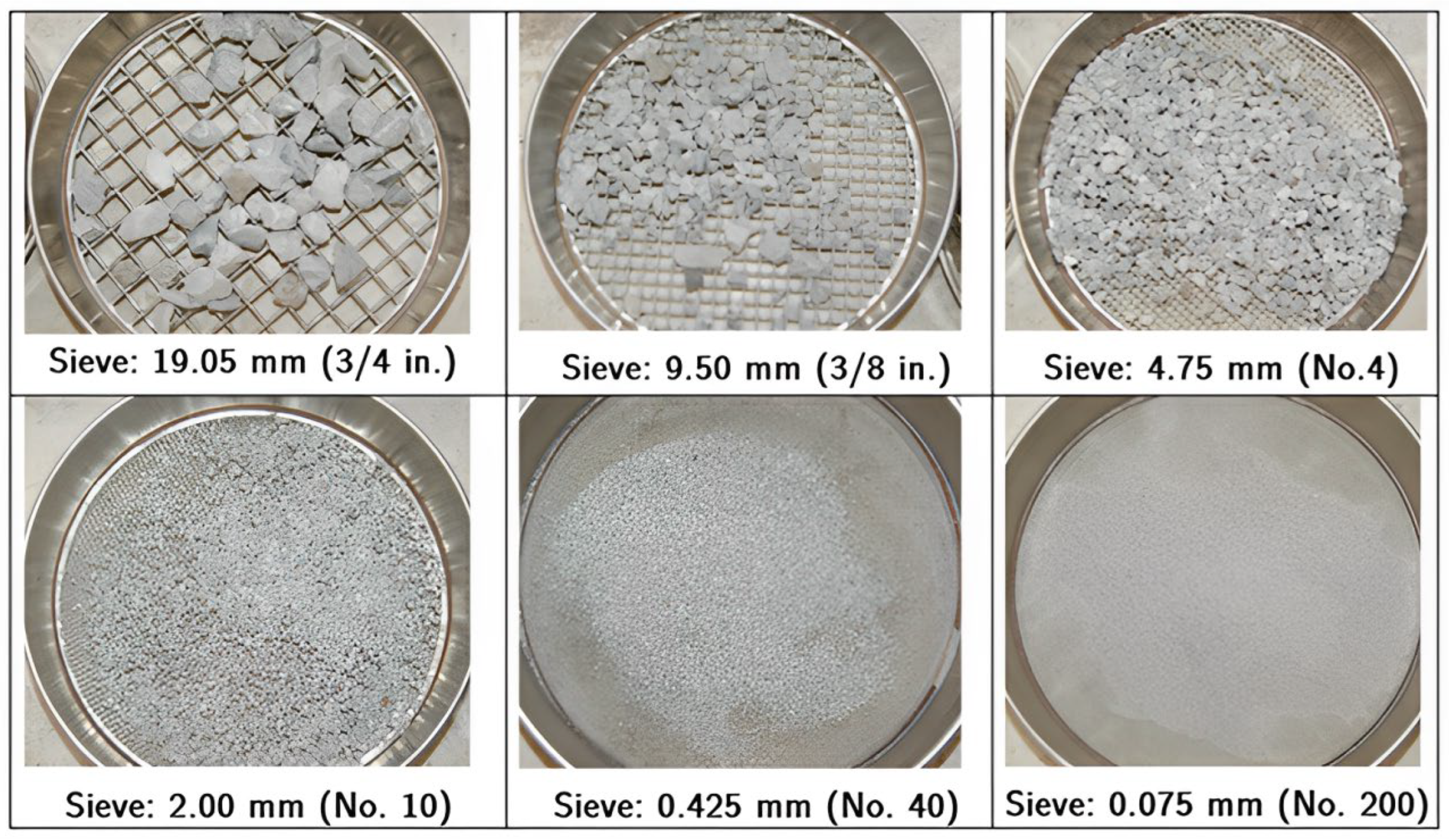
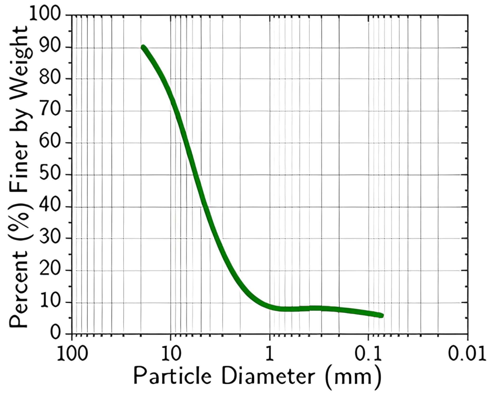
The mechanical response of MASH strong soil during impact loading is governed by interactions between neighboring particles. These interactions, involving both friction and rapid collision, govern the redistribution and dissipation of energy throughout the material. The soil used in most crash testing of soil-based barrier systems and soil-embedded support structures, such as signs and luminaires, is typically well-drained and maintained at a relatively low moisture content to ensure consistency in performance evaluation [54,55,56,57,58,59,60,61]. The grain size distribution of MASH strong soil spans a wide range, from coarse gravel-sized particles to fine silt, as illustrated in Figure 2. Due to the interactions among its constituent particles, MASH strong soil exhibits complex mechanical behavior that reflects characteristics typically associated with multiple states of matter.
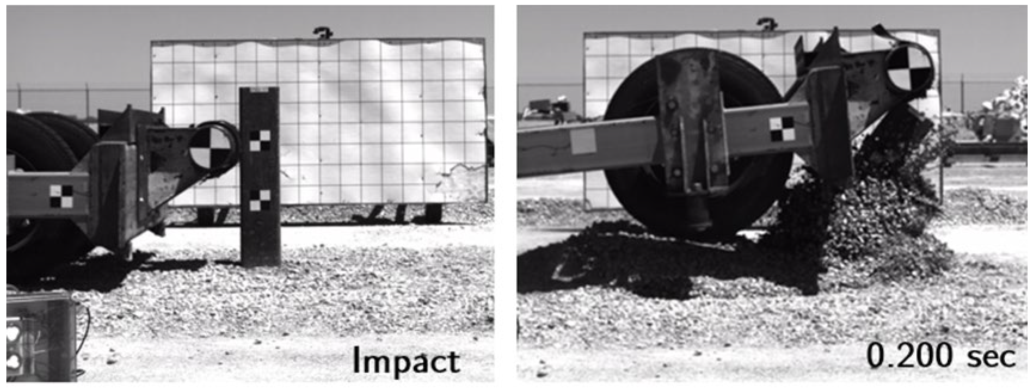
As shown in Figure 3, its response differs significantly from that of conventional engineering materials. Under static loading conditions, it may be treated as a bulk solid with relatively stable mechanical properties. In contrast, under dynamic impact conditions, its motion and deformation are often governed by mechanisms that resemble fluid behavior, where inter-particle collisions and momentum exchange dominate. This diverse phenomenological behavior makes MASH strong soil a particularly compelling subject of study. Its ability to transition between solid-like and fluid-like responses presents unique challenges and opportunities for researchers and engineers. A deeper understanding of this behavior is essential for improving crash testing methodologies and for advancing numerical modeling techniques applied to soil-embedded roadside safety systems.

1.3. Scope, Objectives, and Contribution of the Study

The selection of a soil constitutive model for simulating dynamic soil–structure interaction is a decision that rests with the numerical analyst. However, this decision requires a technical understanding of the features that characterize soil behavior under impact loading, and of whether a given model is capable of representing those features in the context of numerical analysis. This paper examines soil constitutive models available in the LS-DYNA hydrocode that have been used in geotechnical simulations involving soil-embedded barrier and containment systems. The models considered include elastic, simple elastoplastic, advanced elastoplastic, elasto-viscoplastic, and multi-surface or nested formulations.
While these models are widely implemented in practice, there has been little work devoted to their theoretical evaluation for problems involving high frequency dynamic loading, such as vehicular impacts. No prior studies have systematically examined the applicability, limitations, and underlying assumptions of these models within the framework of crash test simulations involving dynamic soil–structure interaction processes. A careful examination of these models is necessary to clarify how well each one captures the dominant features of granular soil behavior under dynamic loading. This study reviews the theoretical basis of selected LS-DYNA soil models and evaluates their capabilities and limitations when applied to problems involving soil-embedded systems subjected to impact loading. The intent is to support a more informed approach to the selection and application of constitutive models in computational analyses of soil response during crash testing.

2. Elastic Models

Elastic models were among the earliest tools employed in geotechnical engineering, particularly for estimating foundation settlement using classical approaches, such as Boussinesq theory. The theory of elasticity provides a robust framework for analytical solutions to a range of boundary value problems and continues to offer first-order approximations for the deformation and stability of geotechnical systems where loading remains well below failure thresholds.
Within the LS DYNA simulation environment, two elastic models applicable to granular soils, including MASH strong soil, are available: the Elastic model and the Biot Hysteretic model. These represent isotropic hypoelastic and viscoelastic material formulations, respectively. While both are mathematically tractable and often used for solid granular elements, they exhibit important limitations when applied to dynamic soil–foundation interaction processes under vehicular impact loading.
Elastic models neglect critical aspects of granular soil behavior, including yielding, strain rate dependence, and stress-dependent stiffness and strength. They also fail to capture volume change associated with dilatancy or contractancy during shear loading. Furthermore, experimental studies have demonstrated that the stress range over which granular soils behave elastically is exceedingly narrow [63,64,65]. Consequently, the applicability of these models in impact simulations is limited. A brief theoretical overview of each model is provided below.

2.1. Hypoelastic Model

This material model implements an isotropic hypoelastic formulation, which defines the stress increment as a function of current stress and strain increments. The term “hypoelastic” refers to its incremental nature, indicating that elasticity is defined in a lower-order or differential sense. This allows for path-dependent behavior and makes the model suitable, to a limited extent, for approximating aspects of hardening or softening in granular materials. [64,65,66,67,68]. In the following, the general aspects of the hypoelastic soil model are considered.
The general form of a constitutive relation is given as follows:
f σ , σ ˙ , ε , ε ˙ = 0
where and are the stress and stress rate, and and are the strain and strain rate, respectively.
A particular form of Equation (1) is given as follows:
σ ˙ i j = f i j σ k l , ε ˙ k l
In hypoelastic models, the response functions are not time-dependent and depend only on the stress tensor:
σ ˙ i j = C i j k l ε ˙ k l
For isotropic hypoelasic granular soil, this becomes the following:
σ ˙ i j = a 0 ε ˙ k k δ i j + a 1 ε ˙ i j + a 2 ε ˙ k k σ i j + a 3 σ m n ε ˙ m n δ i j + a 4 σ i m ε ˙ m j + ε ˙ i m σ m j           + a 5 ε ˙ k k σ i m σ m j + a 6 σ m n ε ˙ n m σ i j + a 7 σ m n σ n k ε ˙ k m δ i j             + a 8 σ i m σ m k ε ˙ k j + ε ˙ i m σ m k σ k j + a 9 σ m n ε ˙ n m σ i k σ k j + a 10 σ m n σ n k ε ˙ k m σ i j + a 11 σ m n σ n k ε ˙ k m σ i r σ r j
The coefficients a 0 , a 1 , a 2 , .............. , a 11 are functions of stress invariants. This general formulation is widely discussed in the literature in hypoelasticity and has been used to derive specific forms for different hypoplastic grades [66,67,68,69,70] to obtain special forms of various grades or orders of the hypoelastic model. For example, in a grade-zero hypoelastic model, the constitutive equation is assumed to be independent of stress; the simplified form is as follows:
σ ˙ i j = a 0 ε ˙ k k δ i j + a 1 ε ˙ i j
with   a 0 = λ and a 1 = μ , where λ and μ are Lame’s constants. Equation (5) corresponds to the generalized Hooke’s law in the following rate form:
σ ˙ i j = K 2 G 3 ε ˙ k k δ i j + 2 G ε ˙ i j
This relation can also be expressed in incremental form as follows:
d σ i j = K 2 G 3 d ε k k δ i j + 2 G d ε i j
The theoretical basis and implementation of hypoelastic soil models, particularly in the context of granular and cohesionless materials, have been explored in several seminal works. These include the early formulations by Truesdell [66,67], studies on recoverable deformation in cohesionless soils by Coon and Evans [68], the finite element implementation of hypoelasticity by Mysore [69], and investigations of elastic behavior in cohesionless soils by Holubec [70].

2.2. Biot Hysteretic Model

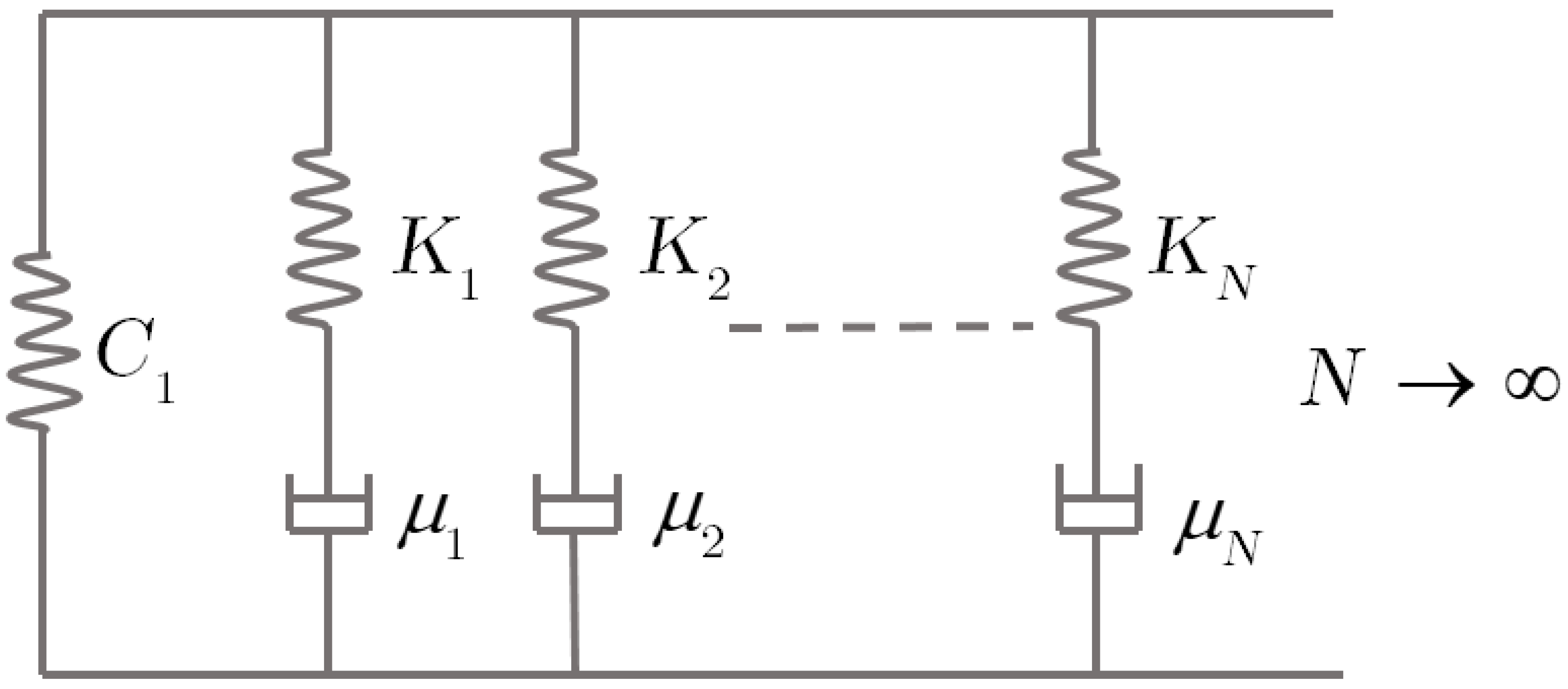
In his foundational paper titled Linear Thermodynamics and the Mechanics of Solids, Biot [71], proposed a viscoelastic model that describes hysteretic behavior as the limiting case of a general viscoelastic formulation. This model combines a linear elastic (Hookean) element in parallel with an infinite number of Maxwell elements, each defined by a specific stiffness and relaxation time [72]. The Biot hysteretic model is a linear viscoelastic formulation that can simulate the nearly frequency-independent response of granular materials subjected to cyclic or earthquake loading.
The implementation of this model in LS-DYNA is referred to as the Biot Hysteretic model. It enables time-domain viscoelastic analysis for materials, such as granular soils [73]. In this formulation, stress is expressed as a convolution integral of the strain rate with a relaxation modulus:
σ i j t = 0 t C R t ξ ε ˙ i j ξ d ξ
where σ i j t is the stress at the current time? t , ε ˙ i j is t strain rate history, and C R t is the relaxation modulus. The relaxation modulus describes the stress response at time t due to a unit step strain applied at time ξ where ξ ξ t .
The relaxation modulus is defined as follows:
C R t = C 1 1 + 2 η π E i β t
In this expression, η = C 2 C 1 is the hysteretic damping coefficient,   β = 2 π F D 10 where F D is the dominant excitation frequency in Hz, and E i x is the exponential integral given by [73]:
E i x = X e ξ ξ d ξ
A schematic representation of Biot’s hysteretic model is shown in Figure 4. It consists of a spring with stiffness C 1 in parallel with an infinite number of Maxwell elements, each represented by a spring and dashpot stiffness K i , and relaxation time μ i .

2.3. Advantages and Limitations of Elastic Soil Models

The advantages and limitations of elastic models implemented in LS-DYNA, namely Hypoelastic model and Biot Hysteretic model are presented in Table 1. These models are sometimes used in the computational analysis of dynamic soil–structure interaction problems, including large deformation simulations of pile–soil systems. While both models are relatively easy to implement and require a limited number of input parameters, they are not well suited for problems involving nonlinear or strain rate-dependent behavior, particularly under impact loading conditions.

3. Simple Elastoplastic Models

Simple elastoplastic constitutive models are frequently employed in LS-DYNA simulations to represent soil behavior under blast loading, tire–soil interaction, and quasi-static soil–foundation systems [73,74,75,76,77,78,79]. A theoretical overview of each model is presented below, followed by a discussion of its advantages and limitations in modeling dynamic soil–structure interaction processes.

3.1. Soil and Foam Model

The Soil and Foam model is a pressure-sensitive, elastoplastic formulation initially developed by Kraig [80] to simulate the behavior of cellular concrete. It is one of the simplest soil models available in LS-DYNA. The model incorporates a yield surface defined in terms of mean and deviatoric stress, allows for elastic unloading, and includes a tensile cut-off criterion. The yield surface has a parabolic form capped by a pressure-dependent ellipsoidal boundary. The stress response is elastic at small strains, while nonlinear behavior due to void collapse and plastic deformation appears at larger strains. Shear strength increases with confining pressure due to cohesion and frictional effects.
The yield function is defined in terms of the second invariant of deviatoric stress J 2 = 1 2 s i j s i j and mean stress p , expressed as follows:
ϕ = p f J 2 a 0 + a 1 p + a 2 p 2 = 0
where a 0 , a 1 , and a 2   are material constants and f is a function of the mean total strain. The deviator stress is as follows:
s i j = σ i j + p δ i j
in which δ i j is the Kronecker delta, and the pressure is linked to the stress trace as follows:
p = 1 3 σ k k
The theoretical formulation becomes more tractable by introducing two scalar functions, one describing the deviatoric part of the yield surface and the other representing a plane orthogonal to the hydrostatic axis [80]:
ϕ s = J 2 a 0 + a 1 p + a 2 p 2
ϕ p = p f
The total strain rate ε ˙ i j is separated into volumetric strain rate, e ˙ i j and the deviatoric strain rate, E ˙ i j , as follows:
e ˙ i j = 1 3 ε ˙ k k δ i j
E ˙ i j = ε ˙ i j 1 3 ε ˙ k k δ i j
Plastic volumetric behavior is determined by evaluating whether the stress state lies on the yield surface and whether the loading condition is active:
ϕ p = 0   and   ϕ ˙ p = 0
If these conditions are not met, the material behaves elastically in the volumetric mode:
p ˙ = 3 K e ˙ i j
where K   is the bulk modulus. Similarly, the deviatoric response is elastic if ϕ s < 0   or ϕ s = 0 and ϕ ˙ s < 0 .
In this case, the stress increment is as follows:
s ˙ i j = 2 G ε ˙ i j
where   G is the shear modulus. For loading on the yield surface,
ϕ s = 0     and   ϕ s s i j s ˙ i j 0
a plastic correction is required. The elastic deviatoric strain rate is
E ˙ e i j = s ˙ i j 2 G
and the plastic deviatoric strain rate is given as follows:
E ˙ p i j = ε ˙ i j E ˙ i j e
The model assumes associative flow in deviatoric stress space:
E ˙ p i j = λ ϕ s s i j
where λ   is a plastic multiplier determined from the consistency condition:
ϕ ˙ s = ϕ s s i j s ˙ i j + ϕ s p p ˙ = 0
Given ϕ s   depends on J 2 is, its gradient is
ϕ s s i j = J 2 s i j = s i j
which leads to the following relation between stress rate and pressure rate:
s i j s ˙ i j = a 1 + 2 a 2 p p ˙
An expression for s ˙ i j   is derived as
s ˙ i j = 2 G ε i j λ s i j
and the plastic multiplier is
λ = s i j E ˙ i j p a 1 + 2 a 2 p p ˙ 2 G s i j s i j
Substitution into Equation (28) provides the stress rate update:
s ˙ i j = 2 G ε ˙ i j 2 G s i j ε i j a 1 + 2 a 2 p p ˙ s i j s i j s i j
Since the deviatoric plastic strain increment is normal to the yield surface, the model does not predict volumetric plastic strain during shear. This restriction fails to capture dilation, which is frequently observed in dense granular soils under dynamic shear due to the disruption of interparticle arrangements. This limitation is critical for simulations of dynamic soil–structure interaction processes where granular fill exhibits volumetric expansion under impact.

3.2. Soil and Foam Failure Model

The Soil and Foam Failure model shares the same constitutive structure as Soil and Foam model. The key distinction is the inclusion of a failure pressure parameter that defines the tensile strength limit. Once this pressure is exceeded, the soil element loses tensile load-carrying capacity. The theoretical formulation remains unchanged from the preceding model.

3.3. Pseudo-Tensor Model

The Pseudo-Tensor model is one of the earliest constitutive formulations in LS-DYNA [73]. It was originally developed to simulate reinforced concrete, but can be adapted to granular materials by disabling reinforcement-related parameters [77]. The model defines independent surfaces for pressure-dependent compaction and shear failure. Two response modes are supported. In mode I, the user defines the pressure-dependent strength behavior of the soil through tabulated data, typically representing the deviatoric stress (stress difference) as a function of mean pressure, thereby enabling accurate calibration to experimental triaxial test results. Mode II allows for the definition of two shear strength curves and includes a damage parameter for progressive failure. Mode II is especially useful when only unconfined compressive strength is available. Reinforcing bars can also be modeled in a smeared representation. Despite this flexibility, the model is not appropriate for simulating unreinforced granular soils under low-confinement impact conditions. Therefore, it is excluded from further detailed theoretical discussion.

3.4. Advantages and Limitations of Simple Elastoplastic Soil Models

The advantages and limitations of the previously discussed simple elastoplastic models, i.e., Soil and Foam, Soil and Foam Failure, and Pseudo-Tensor for large deformation computational modeling of dynamic soil–structure interactions processes, are summarized in Table 2.

4. Elastoplastic Models

Soil constitutive models in this category include Soil Concrete, Mohr–Coulomb, Drucker–Prager, and Jointed Rock. These models are widely implemented in commercially available finite element software and are commonly applied in geotechnical foundation design. A theoretical overview of their elastoplastic frameworks is presented below.

4.1. General Elastoplasticity Framework

The foundational assumption of elastoplastic soil models is that the strain and strain rates decompose into elastic and plastic parts:
ε ˙ i j = ε ˙ i j e l + ε ˙ i j p l
where ε ˙ i j is the total strain rate tensor, ε ˙ i j e l is the elastic part, and ε ˙ i j p l is the plastic part.
The elastic strain rate follows Hooke’s law:
ε ˙ i j e l = s ˙ i j 2 G + 1 2 ν 3 E σ ˙ k k δ i j
where s ˙ i j   is the deviator stress rate tensor, G is shear modulus, ν is Poison’s ratio, E is Young’s modulus, and δ i j is the Kronecker delta tensor. The term σ ˙ k k = σ ˙ x x + σ ˙ y y + σ ˙ z z . For simplicity, elastic constants G , E , and ν are treated as constant. Although they are known to vary with stress state in granular soils [81,82,83,84,85].
Following Hill [86], the plastic strain rates are proportional to the derivative of the plastic potential function g with respect to stresses:
ε ˙ i j p l = λ ˙ g σ i j
Here, λ ˙ is the rate form of the plastic multiplier, which is positive in plastic flow and zero in elastic behavior. The plastic potential function defines the direction of plastic strain increments and may or may not coincide with the yield function f . The associate flow rule implies g = f ; the non-associated rule g Ē f .
The plastic multiplier satisfies the conditions:
λ ˙ = 0   for   f = 0   or   f < 0   and   d f < 0           ( elastic or plastic unloading )
λ ˙ < 0   for   f = 0   and   d f = 0           ( plastic loading )
The Prager consistency condition enforces that the stress state remains on the yield surface during plastic flow:
d f = f σ i j d σ i j = 0
This guarantees that the new stress state σ i j + d σ i j after loading fulfills the yield criterion. Thus, a material point remains in the plastic state. The consistency condition is expressed as follows:
f σ i j + d σ i j = f σ i j + d f = f σ i j
Substituting Equations (31) and (32) into the total strain rate provides the following:
ε ˙ i j = s ˙ i j 2 G + 1 2 ν E σ ˙ k k δ i j + λ ˙ g σ i j
The total stress tensor is written as follows:
σ i j = s i j + 1 3 σ k k δ i j
Substituting this into the governing formulation yields the general elastoplastic stress–strain relation:
σ ˙ i j = 2 G e ˙ i j + K ε ˙ k k δ i j λ ˙ K 2 G 3 g σ p q δ p q δ i j + 2 G g σ i j
in which i   and j are free indices; p   and q are dummy indices, e ˙ i j = ε ˙ i j 1 3 ε ˙ i j δ i j is a deviator shear strain rate, and K is the bulk modulus.
The bulk and shear moduli are related to the elastic modulus as follows:
G = E 2 1 + ν     and   K = E 3 1 2 ν
The rate of the plastic multiplier is obtained from:
λ ˙ = 2 G ε ˙ i j f σ i j + K 2 G 3 ε ˙ k k f σ i j δ i j 2 G f σ p q g σ p q + K 2 G 3 f σ p q δ p q g σ p q δ p q
Once f and   g are specified, the above framework can fully determine the stress evolution of elastoplastic materials.

4.2. Soil Concrete Model

The Soil Concrete model shares several features with the Soil and Foam model. However, it provides additional capabilities for simulating crack initiation and post-peak softening, including residual strength. The reader is referred to the earlier theoretical description of Soil and Foam for its base framework. This model was primarily developed to capture the behavior of concrete, including tensile cracking and post-cracking stiffness reduction. It is not suitable for modeling dynamic impact responses of granular soils such as MASH strong soil, which are typically encountered in roadside safety applications. For this reason, the Soil Concrete model is not included in the present theoretical evaluation of soil constitutive models applicable to roadside safety systems.

4.3. Mohr–Coulomb

The Mohr–Coulomb model is a non-associated elastoplastic model that uses a Mohr–Coulomb yield surface defined by friction angle and cohesion. The dilation and friction angles can vary as functions of accumulated plastic strain [73]. The Mohr–Coulomb (MC) model is widely used in geotechnical and foundation engineering due to its relatively simple form and minimal input requirements, which can be obtained from routine laboratory testing [87]. In addition to two elastic parameters, Young’s modulus E and poison’s ratio ν the model requires three parameters for plastic behavior: the friction angle ϕ , the cohesion c , and the dilation angle ψ . The dilation angle is less frequently reported than the friction angle or cohesion, but can be measured using drained triaxial compression testing.
The MC yield criterion generalizes Coulomb’s friction law to three-dimensional stress states. Yield occurs when one of the following is satisfied:
f 1 = σ 1 σ 2 + σ 1 + σ 2 sin ϕ 2 c cos ϕ = 0 f 2 = σ 2 σ 3 + σ 2 + σ 3 sin ϕ 2 c cos ϕ = 0 f 3 = σ 1 σ 3 + σ 1 + σ 3 sin ϕ 2 c cos ϕ = 0
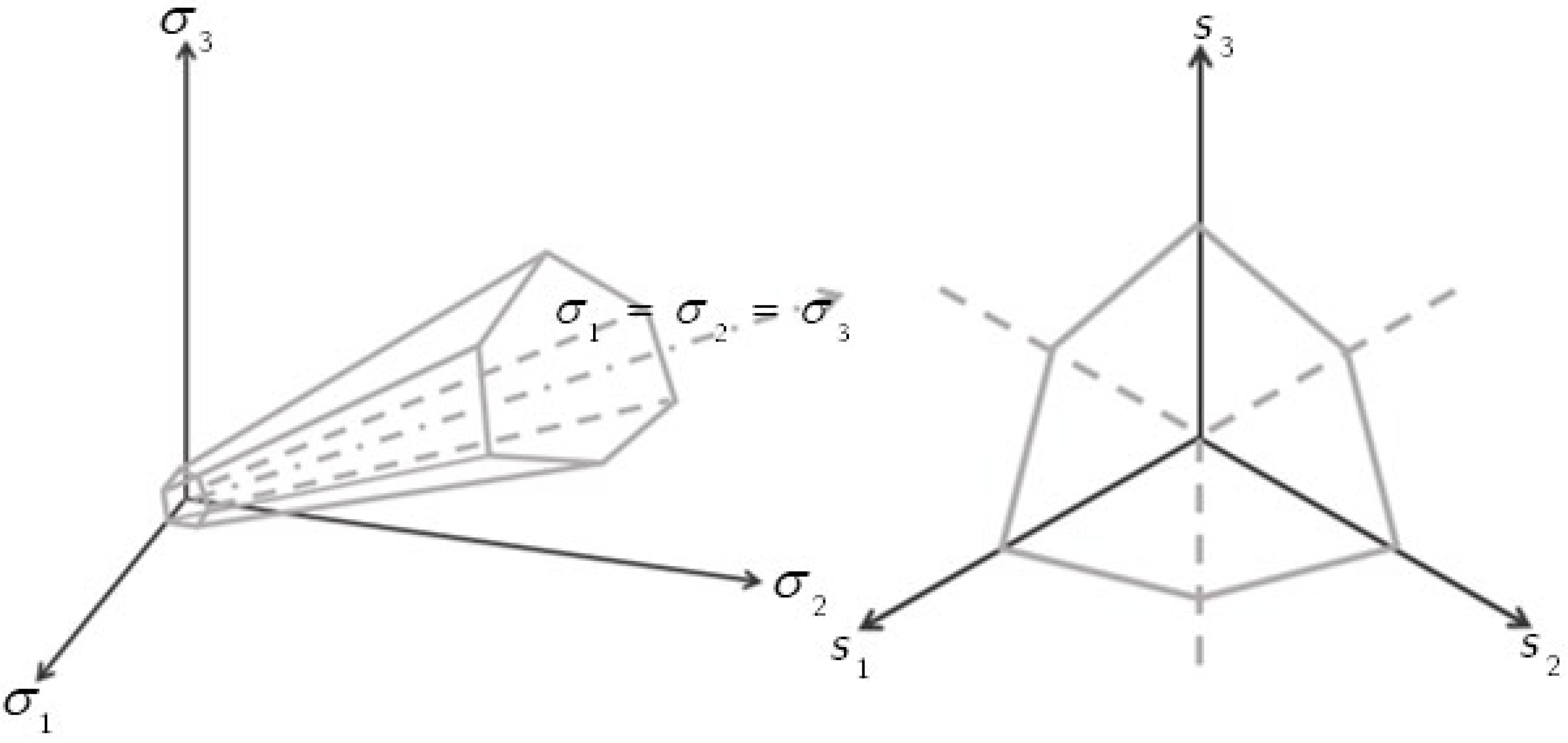
where σ 1 σ 2 σ 3 are the principal stresses. These expressions define a yield surface that forms a pyramid in principal stress space. Since soils cannot sustain tensile stresses, the surface is truncated along the planes σ 1 = 0 , σ 2 = 0 , and   σ 3 = 0 . In the deviatoric plane, the cross-section of the yield surface is a noncircular hexagon, as illustrated in Figure 5.
The non-associated plastic potential functions for each stress pair are as follows:
g 1 = σ 1 σ 2 + σ 1 + σ 2 s i n ψ g 2 = σ 2 σ 3 + σ 2 + σ 3 s i n ψ g 3 = σ 1 σ 3 + σ 1 + σ 3 s i n ψ
in the associated flow case ψ = ϕ .

4.4. Drucker Prager Model

The Drucker Prager model is a pressure-sensitive elastoplastic formulation developed by modifying the von Mises yield criterion to incorporate confinement effects [88]. The Drucker–Prager yield function is given as follows:
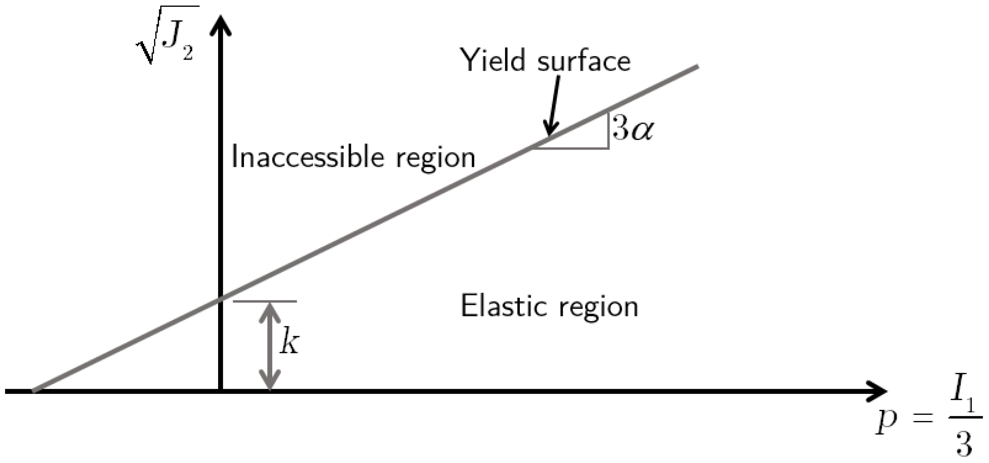
f = J 2 α I 1 k = 0
in which J 2 is the second invariant of the deviatoric stress tensor, I 1   is the first stress invariant, and α   and k   are material constants related to friction and cohesion, respectively. For purely cohesive materials α = 0 , and the yield criterion reduces to von Mises form. The second invariant of deviator stress and first invariant of stress tensors are defined as follows:
J 2 = 1 2 s i j s i j                 and                 I 1 = σ 11 + σ 22 + σ 33
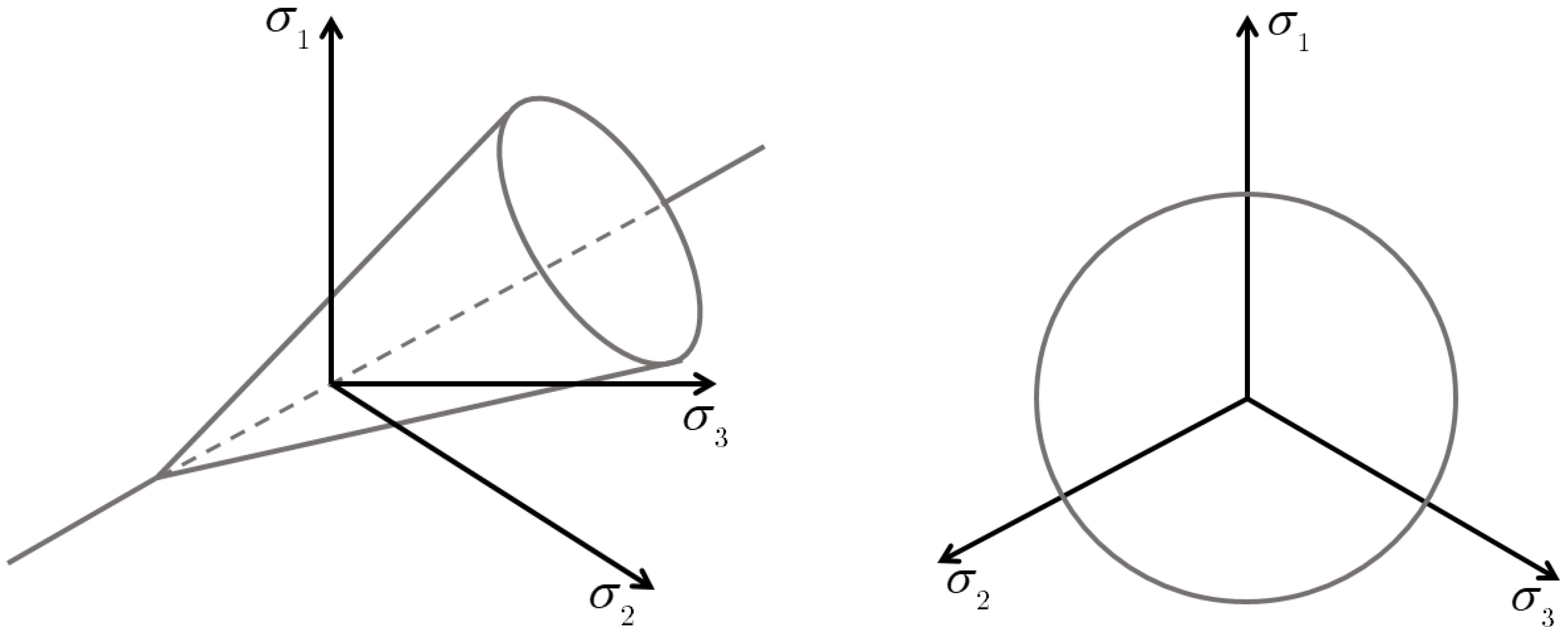
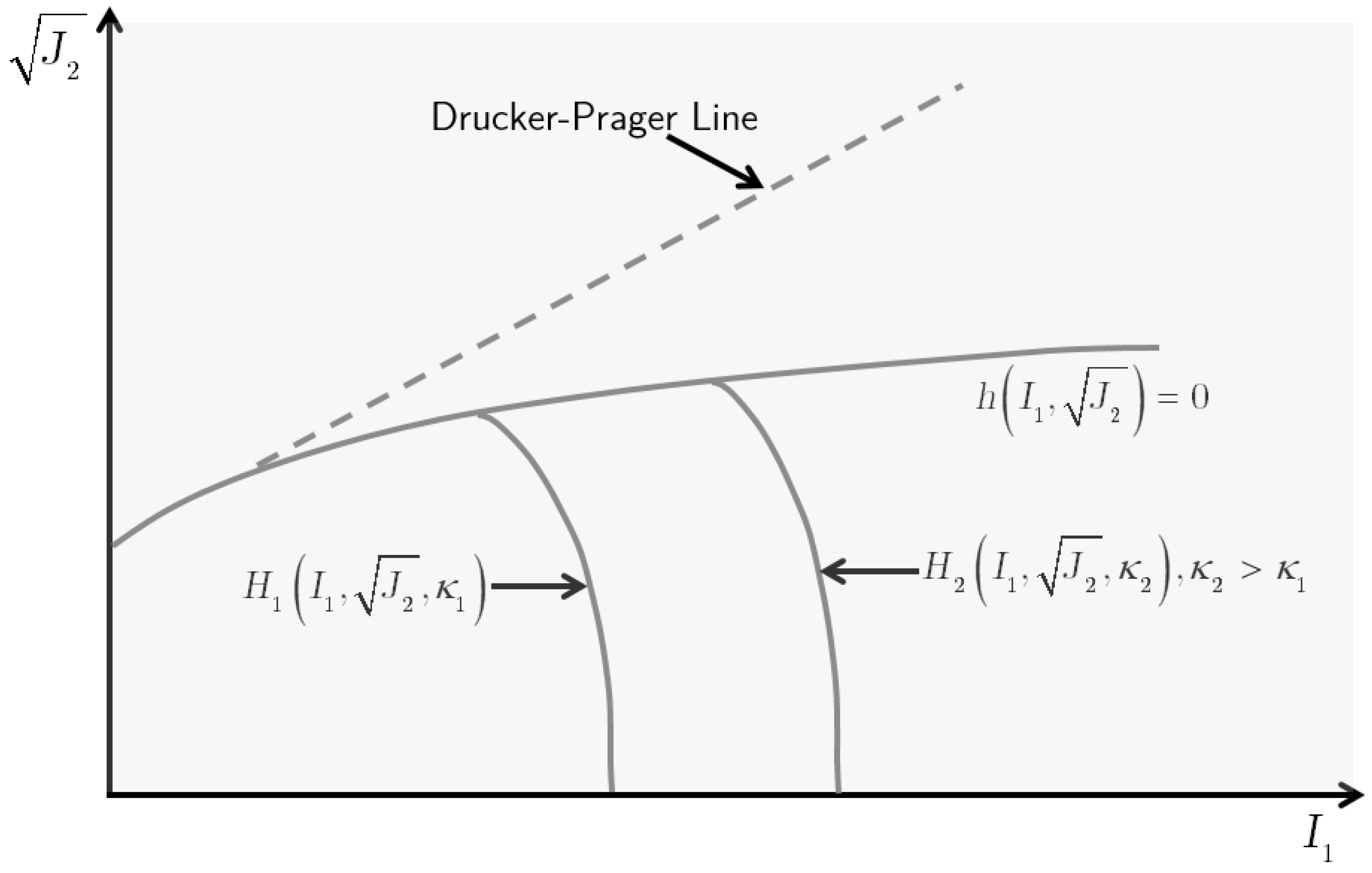
Figure 6 illustrates the yield surface in the principal stress space as a circular cone, and Figure 7 shows its projection in the J 2 p   plane.
When the yield function is not satisfied:
f = J 2 α I 1 k < 0 ,   or   f = 0   and   d f = f σ i j d σ i j < 0
σ ˙ i j = K ε ˙ k k δ i j + 2 G e ˙ i j
When yielding occurs:
f = 0     and   d f = 0
σ ˙ i j = K ε ˙ k k δ i j + 2 G e ˙ i j λ ˙ 3 K α δ i j + G s i j J 2
The rate of the plastic multiplier is computed from the following:
λ ˙ = 3 K α ε ˙ k k + G J 2 s p p e ˙ p q 9 K α 2 + G
Material constants, α   and k   are related to the friction angle ϕ and cohesive c as follows [89,90,91]:
α = 2 sin ϕ 3 3 sin ϕ   and   k = 6 c cos ϕ 3 3 sin ϕ
Plastic volumetric strain rate is as follows:
ε ˙ k k p = 3 α 3 K α ε ˙ k k + G J 2 s p q e ˙ p q 9 K α 2 + G
This expression shows that the model inherently produces volumetric expansion during shear, representing dilation behavior due to scalar nonlinearity [89].

4.5. Jointed Rock Model

The Jointed Rock model is an anisotropic elastoplastic model developed to represent jointed or stratified rock masses. Anisotropy may be elastic, characterized by different stiffness in different directions, or plastic, represented by varying friction angle, cohesion, and dilation angle across planes of weakness. The LS-DYNA implementation does not include kinematic hardening [83].
The model assumes that the rock matrix behaves as a transversely anisotropic elastic material, with up to three orthogonal joint sets that limit shear and tensile strength in specified directions. Each plane may have independent shear strength properties. Tensile stresses normal to the joints are capped by tension cut-off values. Sliding is activated once shear strength is reached in any joint direction.
The Mohr–Coulomb failure criterion limits the shear stresses in the principal joint direction. Thus, plastic sliding will occur when maximum shear stress is reached in the principal joint direction. In the Jointed Rock model, a maximum of three sliding planes or directions can be defined. The first direction is assumed to coincide with the plane of elastic anisotropy, and each direction can have different shear strength properties. Also, a predefined tension cut-off, i.e., tensile strength, limits the tensile stresses perpendicular to the three planes.
This model is applicable when rock masses contain regular, parallel joint sets and no fault gouge. However, it is not suitable for modeling granular soils used in crash testing of soil-embedded roadside safety structures. Therefore, it is excluded from further analysis in the present study. For detailed formulation, the reader is referred to [92,93,94,95].

4.6. Advantages and Limitations of Elastoplastic Soil Models

The Drucker–Prager model overestimates frictional resistance in non-axisymmetric stress states due to its circular deviatoric projection. Both Drucker–Prager and Mohr–Coulomb models require elastic parameters that are difficult to define for granular soils, which exhibit nonlinear inelastic response from the onset of deformation. Additionally, these models cannot represent pore pressure generation during undrained shear under dynamic loading. The main advantages and limitations of the Mohr–Coulomb and Drucker–Prager models for modeling dynamic soil–structure interaction processes are summarized in Table 3.

5. Elasto-Viscoplastic Model

5.1. FHWA Model

The FHWA soil constitutive model was developed by APTEK, Inc. to simulate the mechanical behavior of granular soils under impact loading in crash tests, particularly those governed by NCHRP Report 350 protocols [96]. This model integrates a regularized Mohr–Coulomb yield surface based on the framework proposed by Abbo and Sloan [97], and incorporates critical features necessary for modeling realistic soil response in roadside safety applications. These features include confinement-dependent strength, rate sensitivity, strain softening, pore pressure evolution, and numerical erosion.
The model is formulated within an elasto-viscoplastic framework. The elastic response follows isotropic linear elasticity, consistent with Hookean behavior typically observed in compacted, well-graded soils. The plastic response is governed by a regularized Mohr–Coulomb yield function, while rate-dependent effects are introduced via a Duvaut–Lions-type viscoplastic regularization scheme.

5.1.1. Elastic Response

The elastic strain rate tensor is governed by classical linear elasticity:
ε ˙ i j e l = s ˙ i j 2 G + 1 2 ν 3 E σ ˙ k k δ i j
where s ˙ i j is the deviator stress rate tensor, G is the shear modulus, ν is the Poisson’s ratio, E is the Young’s modulus, σ ˙ k k = σ ˙ 11 + σ ˙ 22 + σ ˙ 33 , and δ i j   is the Kronecker delta.

5.1.2. Yield Condition

The plastic yield condition is a regularized variant of the classical Mohr–Coulomb (MC) criterion, originally formulated to describe frictional failure of granular media. It provides a pressure-dependent shear strength envelope defined in terms of principal stresses as follows:
f = σ 1 σ 3 + σ 1 + σ 3 sin ϕ 2 c cos ϕ = 0
where σ 1 σ 2 σ 3 are the principal stresses (compressive stresses taken as negative), ϕ is the friction angle soil, and c   is the cohesion.
To circumvent the direct evaluation of principal stresses in three dimensions, the criterion is recast using stress invariants [98]:
σ m = 1 3 σ 11 + σ 22 + σ 33
σ ¯ = J 2 = 1 2 s 11 2 + s 22 2 + s 33 2 + σ 12 2 + σ 13 2 + σ 23 2
θ = 1 3 sin 1 3 3 2 J 3 J 2 3 2 30 0 θ 30 0
In which
J 3 = s 11 s 22 s 33 + 2 σ 12 σ 23 σ 13 s 11 σ 23 2 s 22 σ 13 2 s 33 σ 12 2
and
s 11 = σ 11 σ m , s 22 = σ 22 σ m , s 33 = σ 33 σ m
The principal stresses can be expressed in terms of the stress invariants as follows:
σ 1 = 2 3 J 2 sin θ + 120 0 + σ m
σ 2 = 2 3 J 2 sin θ + σ m
σ 3 = 2 3 J 2 sin θ 120 0 + σ m
By substituting Equations (54) and (56) into Equation (53), the MC yield becomes:
f = σ m sin ϕ + J 2 K θ c cos ϕ = 0
where
K θ = cos θ 1 3 sin ϕ sin θ
The MC yield criterion defines a hexagonal pyramid in three-dimensional principal stress space, with its central axis aligned along the hydrostatic axis [99]. In the octahedral plane, corresponding to constant mean stress, the MC yield surface forms an irregular hexagon characterized by sharp vertices where the surface gradient is discontinuous. These corners represent singularities where the first derivative of the yield function is not defined, i.e., the yield function lacks C1 continuity. As stress states in geotechnical applications frequently approach these corners, the lack of smoothness becomes a practical and numerical limitation.
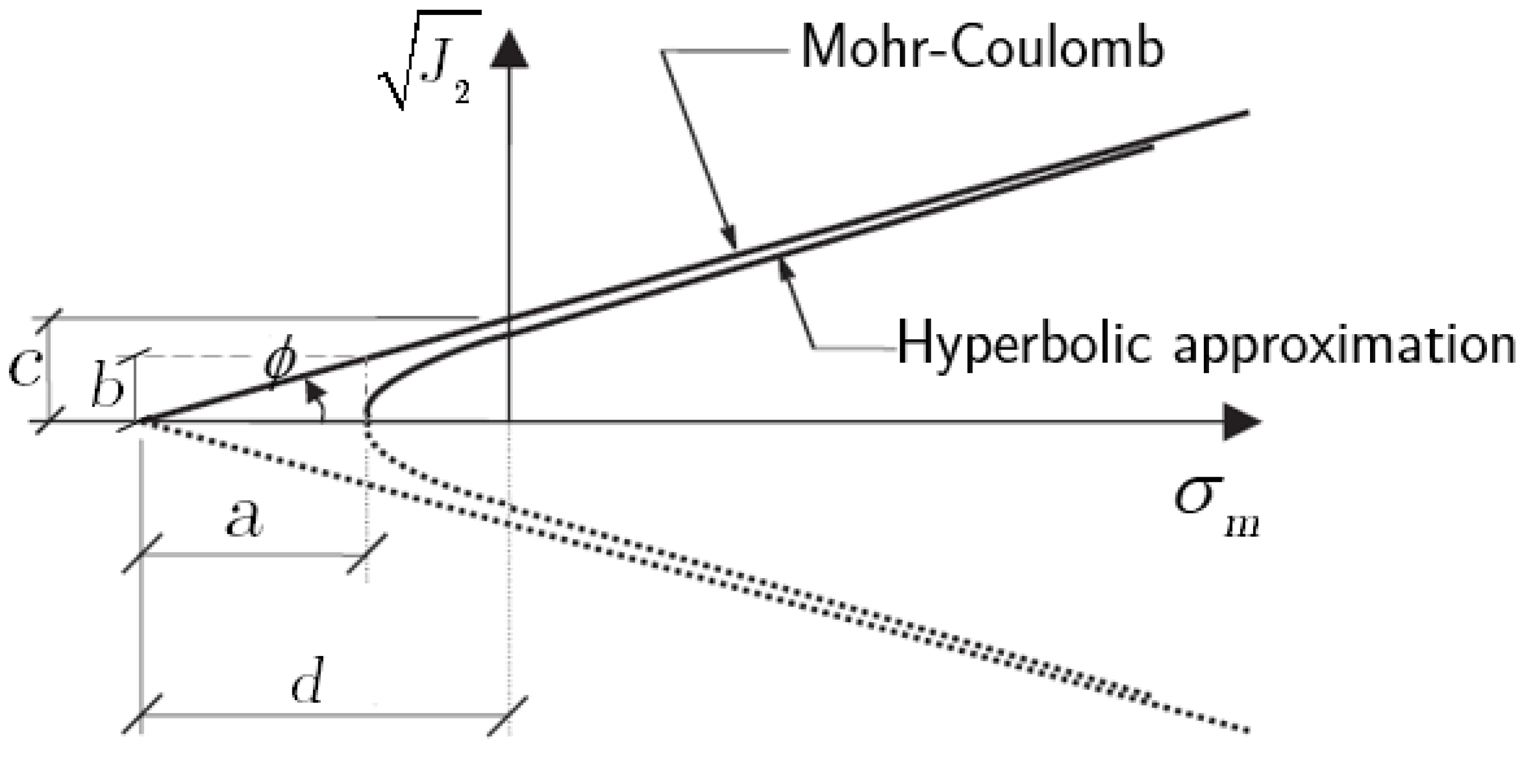
To overcome this deficiency, the FHWA soil model adopts a regularization scheme based on the hyperbolic smoothing approach proposed by Abbo and Sloan [97]. For a fixed Lode angle θ , the MC criterion describes a straight line in the J 2 - σ m   meridional plane, as shown in Figure 8. This line can be expressed as follows:
J 2 = 1 K θ c cos ϕ σ m sin ϕ
where the slope is sin ϕ / K θ , and the line intersects σ m -axis at σ m = c cot ϕ . To obtain a differentiable surface, Abbo and Sloan introduced a hyperbolic approximation with asymptotes matching the MC linear yield line [100]. The general form of this asymptotic hyperbola is as follows:
σ m d 2 a 2 J 2 b 2 = 1
where d , a , and b   are geometric parameters defining the curvature and intercepts of the hyperbola in the meridional plane (Figure 8). By matching the slope and intercept of the hyperbola’s asymptote to those of the MC line, the following relations are obtained:
b a = sin ϕ K ϕ , d = c cot ϕ
Substituting Equation (61) into Equation (60), the smoothed yield function is defined as follows:
f = σ m + J 2 K 2 θ + a 2 sin 2 ϕ c cos ϕ = 0
This form recovers the original MC surface when a = 0   , while retaining differentiability near the corners. The degree of regularization can be controlled by the parameter a = 0 .
A second limitation of the MC surface concerns its deviatoric-plane representation. At low confining pressures, typical of roadside barrier installations, granular materials do not follow the hexagonal pattern of the MC criterion. Instead, experimental results indicate a triangular deviatoric yield surface at low confinements [96], as illustrated in Figure 9a. The FHWA model incorporates this behavior by modifying the function K θ following the formulation of Klisinski [101]:
K θ = 4 1 e 2 cos 2 θ + 2 e 1 2 2 1 e 2 cos θ + 2 e 1 4 1 e 2 cos 2 θ + 5 e 2 4 e
The parameter e defines the ratio of triaxial extension to triaxial compression strength, with 0.5 < e 1.0 . A value of e = 1.0   results in a circular, while e = 0.55   produces a triangular deviatoric surface, Figure 9b, consistent with observed behavior under low confinement.

5.1.3. Flow Rule

The elasto-plastic formulation of the FHWA model assumes the additive decomposition of strain rate into elastic and plastic components. The plastic strain rate tensor is governed by a flow rule of the form:
ε ˙ i j p l = λ ˙ g σ i j
where λ   ˙ is a plastic multiplier (or consistency parameter), g   is the plastic potential, and σ i j   is the stress tensor. The plastic multiplier is subject to the Karush-Kuhn-Tucker conditions [102]:
The consistency condition is provided as follows:
λ ˙ φ ˙ σ i j = 0
For dense granular flows dominated by interparticle friction and collisions, the FHWA model employs an associated flow rule, setting the plastic potential equal to the yield function, f . The plastic strain rate becomes the following:
ε ˙ i j p l = λ ˙ f σ i j
The consistency parameter is evaluated as follows:
λ ˙ = 2 G ε ˙ i j f σ i j + K 2 G 3 ε ˙ k k f σ i j δ i j 2 G f σ p q f σ p q + K 2 G 3 f σ p q δ p q f σ p q δ p q

5.1.4. Strain Softening

In dynamic impact scenarios, granular soils surrounding embedded piles display splashing, heaving, and dilation behavior, mimicking a fluid-like response [103,104,105]. To capture this post-yield degradation, the FHWA model integrates a strain energy-based continuum damage formulation [106,107].
The damage initiation criterion, ξ , is defined in terms of plastic volumetric strain ε v p l   as follows:
ξ = 1 K σ m d ε v p l
where σ m = 1 3 σ ˙ k k is the mean stress. For dilative response, ε v p l < 0 . The effective stress is reduced by an isotropic damage parameter D   as follows:
σ i j = σ ¯ i j 1 D
The damage parameter D   evolves from 0 (undamaged) to 1 (complete failure) and is defined as follows:
D = ξ ξ 0 α ξ 0
where α   and ξ 0   are material parameters denoting the initiation and completion of damage, respectively. The peak-to-residual strength degradation is incorporated through a pressure-dependent maximum damage:
D m a x = sin ϕ p e a k sin ϕ r e s sin ϕ p e a k
To mitigate mesh dependency, the model uses a void formation energy parameter:
G f = V 1 3 σ m d ε v p l
where V   is the volume of the element.
The strain at full damage, α , is computed as follows:
α = 2 G f K ξ 0 V 1 3 + ξ 0

5.1.5. Viscoplastic Regularization

Granular materials exhibit dual behaviors: solid-like resistance and fluid-like flow, depending on the loading regime. To accommodate this, the FHWA model applies a viscoplastic regularization based on a two-parameter extension of the Duvaut–Lions formulation [108,109,110,111]. This scheme interpolates between the static yield stress σ ¯ i j and the elastic trial stress σ ¯ i j t r i a l to define viscoplastic stress:
σ ¯ i j v p = σ ¯ i j 1 ς + ς σ ¯ i j t r i a l
ς = η Δ t + η
η = γ ε ˙ e 1 1 n
In which, ς is a stress update parameter, Δ t   is the time step, η is the fluidity parameter, γ is the viscosity parameter, n is the viscosity exponent, and ε ˙ e is the effective strain rate which is expressed as follows:
ε ˙ e = 2 3 e ˙ i j e ˙ i j
with deviator strain e ˙ i j :
e ˙ i j = ε ˙ i j 1 3 ε ˙ k k δ i j
As η = 0 , the solution approaches the inviscid yield surface, as η , plastic flow is surpassed, and the stress state remains elastic.

5.2. Model Capabilities and Limitations

Table 4 summarizes the performance characteristics of the FHWA soil model for crash simulation applications.

6. Cap Models

6.1. Fundamentals of Cap Models

Cap models for geomaterials are formulated within the theoretical framework of work-hardening plasticity under the incremental theory, assuming time-independent material behavior. These models distinguish between elastic and plastic strain components during each loading increment. The total strain rate is expressed as the additive decomposition:
ε ˙ i j = ε ˙ i j e l + ε ˙ i j p l
Elastic deformations are governed by nonlinear stress-dependent moduli:
ε ˙ i j e l = I 1 9 K σ p q δ i j + 1 2 G σ p q s ˙ i j
where I 1 = σ ˙ k k   is the first invariant of the stress tensor, K σ p q and G σ p q   are the bulk and shear moduli, respectively, and s ˙ i j = σ ˙ i j 1 3 I 1   is the deviatoric stress rate, and δ i j   is the Kronecker delta. To ensure path independence of the elastic response, shear and bulk moduli are defined as follows [87]:
G = G J 2 , ε i j p l
K = K I 1 , ε i j p l
The plastic strain rate tensor is derived from the plastic potential surface f and follows a non-associated flow rule under admissible loading conditions:
ε ˙ i j p l = λ ˙ f σ i j     i f   f = 0 and f σ i j σ ˙ i j > 0 0         otherwise
As illustrated in Figure 10, the loading function f for cap models is composed of two distinct surfaces: (1) a shear failure envelope that defines the limit of deviatoric stress, and (2) a hardening cap surface that evolves with volumetric plastic strain. This composite function is defined as follows:
f = h I 1 , J 2 = J 2 Q I 1 on   failure   surface H I 1 , J 2 , κ = J 2 F I 1 , κ on   cap   surface
The cap evolution is characterized by the hardening parameter κ ,   related to plastic volumetric strain:
κ = g ε k k p l
Equation (85) enables both expansion and contraction of the cap, thus allowing control over volumetric dilatancy and preventing unrealistic predictions common in classical Drucker–Prager models.
The plastic stress–strain relations in terms of deviatoric and volumetric components are as follows:
e ˙ i j p l = λ ˙ f s i j = λ ˙ 2 J 2 f J 2 s i j
ε ˙ k k p l = 3 λ ˙ f I 1
ε ˙ i j p l = λ ˙ 1 2 J 2 f J 2 s i j + f I 1 δ i j
The plastic multiplier λ ˙ is determined from the consistency condition:
f ˙ = f I 1 I ˙ 1 + 1 2 J 2 f J 2 s i j s ˙ i j + f κ κ ε k k p l ε ˙ p p p l = 0
The elastic stress–strain relations are recast in deviatoric and volumetric components as follows:
e ˙ i j e l = s ˙ i j 2 G J 2 , ε i j p l
ε ˙ k k e l = I ˙ 1 3 K I 1 , ε i j p l
Using Equations (87), (91), and (92), the consistency condition becomes
3 K ε ˙ k k p l f I 1 + G e ˙ i j e l J 2 f J 2 s i j + 3 λ ˙ f I 1 f κ f ε k k p l = 0
Substituting the total strain rate from Equation (79), and isolating the elastic and plastic contributions results in the following:
3 K ε ˙ k k ε ˙ k k p l f I 1 + G J 2 e ˙ i j e ˙ i j p l f J 2 s i j + 3 λ ˙ f I 1 f κ f ε k k p l = 0
Finally, inserting the expressions for e ˙ i j p l and ε ˙ k k p l from Equations (86) and (87) into Equation (93) and solving for λ ˙ , yields
λ ˙ = 3 K f I 1 ε ˙ k k + G J 2 f J 2 s i j e ˙ i j 9 K f I 1 2 + G f J 2 2 3 f I 1 f κ f ε k k p l
This general form reduces to the elasto-plastic multiplier (Equation (67)) when the loading function does not depend on plastic volumetric strain. Historically, modern cap models evolved from the original two-surface formulations developed by [112,113]. These formulations introduced a composite yield surface composed of a shear failure surface and a hardening cap, with independent evolution laws, enabling accurate modeling of both dilative and compacting behavior in pressure-sensitive geomaterials.

6.2. Geologic Cap Model

The Geologic Cap model in LS-DYNA is formulated in terms of the first and second stress invariants:
I 1 = σ 1 + σ 2 + σ 3
J 2 = 1 6 σ 1 σ 3 2 + σ 1 σ 2 2 + σ 2 σ 3 2
where σ 1 σ 2 σ 3 and compressive stresses are taken as negative.
This two-invariant model describes elastic deformation, shear failure, and cap plasticity through an associated, rate-independent plasticity formulation. The yield surface consists of two intersecting components: a shear failure envelope and a strain-hardening cap. When the stress state lies within the composite surface, the material response is purely elastic. The shear failure surface is defined as follows:
F s = J 2 α + γ exp β I 1 θ I 1
where α , γ , β , and θ are parameters calibrated to the experimental response. Plastic deformation on the shear surface includes both deviatoric and dilatational components.
The cap surface accounts for irreversible volumetric compaction under non-hydrostatic compressive states. It takes an elliptical form:
J 2 = 1 R X κ L κ 2 I 1 L κ 2
where R   controls the ellipticity, κ   is a hardening parameter and, X κ ,   L κ   determine the cap’s location in stress space. These are defined as follows:
The relation between the cap surface shape parameters is provided by the following:
X κ = L κ + R α γ exp β L κ + θ L κ
L κ κ i f κ < 0 0 i f κ 0
The evolution of the cap is governed by a hardening law tied to the plastic volumetric strain rate, defined as follows:
ε ˙ ¯ k k p l = W exp D 1 X X O D 2 X X O 2 1
where W , D 1 , and D 2 are material constants, X 0 denotes the initial cap location. The cap must intersect the shear surface with horizontal tangency, ensuring that the shear envelope represents the critical state line separating compactive from dilative volumetric plastic flow. ε ˙ ¯ k k p l   is a history-dependent functional of ε ˙ k k p l defined as follows:
ε ˙ ¯ k k p l m i n ε ˙ k k p l , 0
Despite its theoretical elegance, the Geologic Cap Model exhibits limitations. The flow direction is not uniquely defined at the cap–shear intersection. Pre-failure dilation is not permitted, contradicting experimental results. Additionally, the numerical requirement of finding a horizontal tangent intersection between the cap and the shear surface incurs significant computational cost. These issues have motivated enhanced formulations, most notably the smooth cap model developed by Schwer and Murray [114,115].

6.3. Schwer Murray Cap Model

The Schwer Murray Cap model is a three-invariant extension of the geologic cap model. It eliminates the discontinuities at the cap–shear interface through a smooth yield surface construction. The model is also referred to as the Continuous Surface Cap model (CSCM) [73]. Figure 11 shows the general shape of the yield surface in both three and two dimensions. To ensure continuity between the cap and shear surfaces, the model utilizes the Pelessone smoothing function [116]. The resulting formulation accounts for isotropic hardening, kinematic shear hardening, and Lode angle dependence. It also accommodates strain rate effects and strain-softening through continuum damage mechanics [111,112,113,114,115,116,117,118].
The general form of the yield function is as follows:
Γ I 1 , J 2 , J 3 , κ , α i j = Γ 2 θ J 2 J 2 α F s N 2 F c
where α i j   is the back-stress tensor, and   J 2 α is the scalar measure of kinematic hardening:
J 2 α = α i j s i j α i j 2
The Lode angle dependence is introduced through the following function:
Γ θ = 1 2 1 + sin 3 θ + 1 ψ 1 sin 3 θ
where ψ is the ratio of the yield stress in triaxial extension to the yield stress in triaxial compression, and the lode angle θ is defined as follows:
θ = 1 3 a sin 27 2 J 3 3 J 2 3 2 f o r π 6 θ π 6 Γ = 1 2 1 + sin 3 θ + 1 ψ 1 sin 3 θ
and the third invariant of deviatoric is as follows:
J 3 = 1 3 s i j s j k s k i
The Pelessone smoothing function used to define the cap region is as follows:
F c I 1 , κ = 1 + I 1 L κ I 1 L κ I 1 L κ 2 X κ L κ 2
The functional form for X κ and L κ are preserved as follows:
X κ = L κ + R α γ exp β L κ + θ L κ
L κ κ i f κ < 0 0 i f κ 0
L κ I 1 X κ and unity for I 1 < L κ , ensuring a smooth yield surface.
Strain rate effects are incorporated via a modified Duvaut–Lions viscoplastic framework, where the dynamic stress state interpolates between the elastic trial stress and the quasi-static yield surface. The model also includes a continuum damage formulation to capture strain-softening under dynamic loading. Implementation details are provided in [111,112,113,114,115,116,117,118].

6.4. Advantages and Limitations of Cap Soil Models

The advantages and limitations of cap models, i.e., Geologic Cap and Schwer Murray Cap for modeling dynamic soil–structure interaction processes, are summarized in Table 5.

7. Nested Surface Models

Nested surface models introduce multiple yield surfaces within the stress space of an element to represent material behavior across different stress levels. In these models, yield surfaces are fixed in stress space and do not translate in response to loading, thus eliminating the need for kinematic hardening rules [119]. This approach is particularly advantageous for cyclic loading simulations, as it captures hysteretic energy dissipation without introducing internal variables for surface motion.
Over the past two decades, nested surface formulations have been employed as viable alternatives to isotropic hardening models for simulating the cyclic response of geomaterial [120]. Within the LS-DYNA simulation environment, two nested surface models are available: Hysteretic Soil and Soil Brick. Only the former is applicable to granular soils typically encountered in roadside safety systems, and thus is the focus of this discussion.

7.1. Hysteretic Soil Model

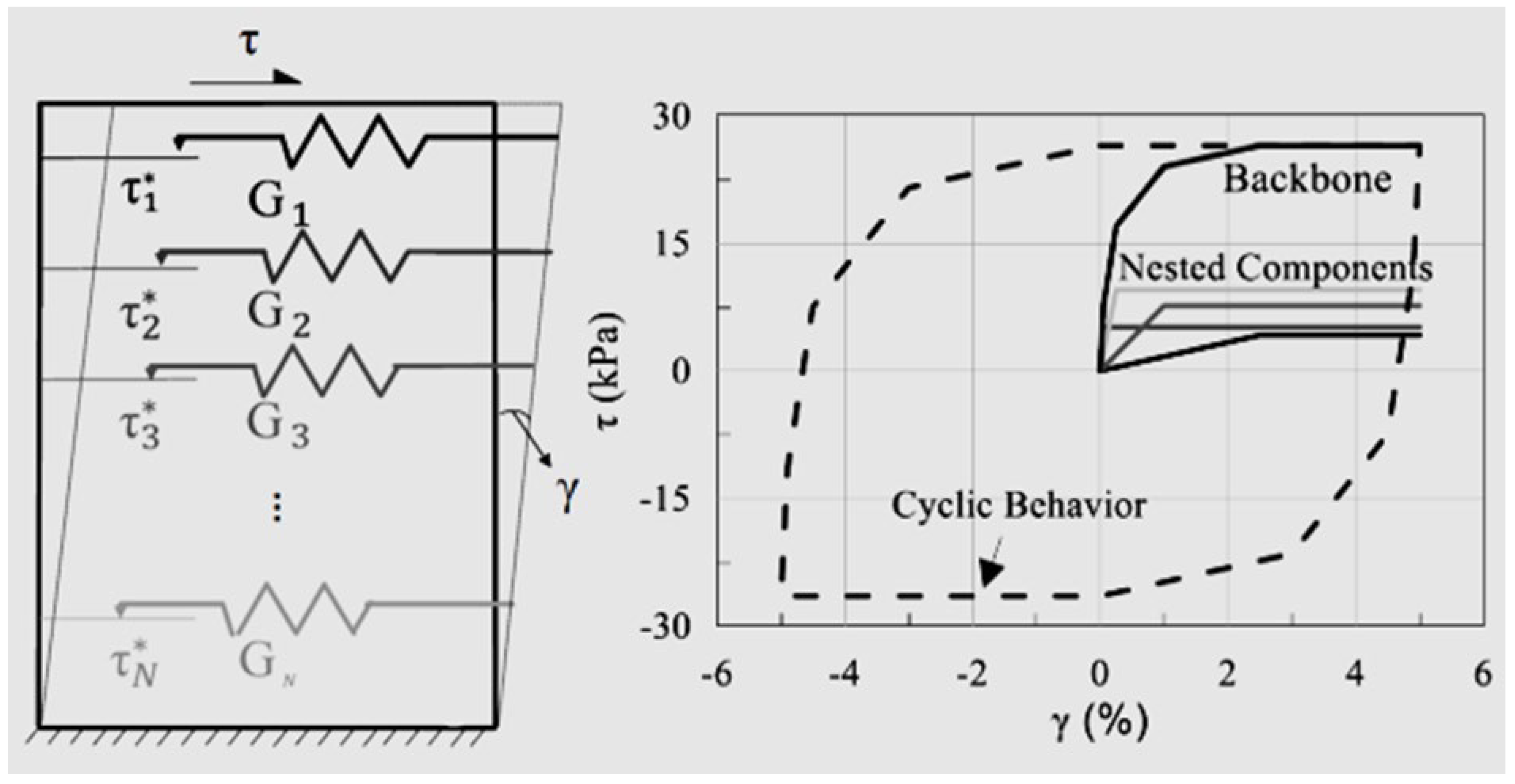
The Hysteretic Soil model is a three-dimensional, piecewise nonlinear, nested surface formulation developed for simulating the inelastic cyclic response of granular soils [73]. It allows for up to ten superposed elastic-perfectly plastic layers, each characterized by distinct elastic moduli and yield thresholds. Hysteretic energy dissipation arises as individual layers yield under increasing deviatoric strain amplitude. The overall deviatoric stress is computed as the sum of contributions from each layer.
The conceptual basis of the model originates from Iwan’s one-dimensional slider-spring system [121], later extended by Chiang and Beck [119] to three dimensions using a von Mises yield criterion and an associated flow rule. The layered structure and the resulting cyclic and monotonic response of a typical four-layer configuration are shown in Figure 12.
In this model, each layer is represented by an elastic-perfectly plastic deviatoric response. The total deviatoric stress tensor is obtained by summing the stress tensors of all layers:
f J 2 = τ y
where J 2   is the second invariant of the deviatoric stress tensor, and τ y   is shear yield stress for a given layer. The model supports up to ten layers, limiting the discretization of the shear stress–strain backbone curve to ten points
To incorporate pressure-dependent yield behavior, a modified Drucker–Prager criterion is available:
τ y p = a 0 + a 1 p p 0 + a 2 p p 0 2 a 0 + a 1 p r e f + a 2 p r e f 2 τ y p r e f
Here, p   is the hydrostatic (mean effective) stress, a 0 , a 1 , and a 2   are curve fitting parameters, p 0 is the cut-off pressure below which failure occurs, and p r e f is the reference pressure. Putting a 0 = 0   a 1 = 0 , and a 2 = 0 results in the classical Drucker–Prager model.
Elastic stiffness moduli are also pressure-dependent and follow a power-law form [123]:
G p = p p 0 p r e f b G p r e f
K p = p p 0 p r e f b K p r e f
where G p and K p are the shear and bulk moduli at confining pressure p , G p r e f   and K p r e f   are the corresponding moduli at reference pressure, and b   is the exponent controlling the pressure sensitivity. This formulation enables the simulation of nonlinear compressibility and shear stiffness evolution with confinement. The model also supports user-defined input for dilatancy and strain rate sensitivity, essential for dynamic loading conditions involving high strain rates and localized volumetric expansion. Details of these features are described in [73].

7.2. Soil Brick Model

The Soil Brick model is a kinematic yield surface formulation implemented in strain space. It accounts for anisotropy and is tailored to model the behavior of over-consolidated clays [124]. The model is not suitable for simulating granular soils, and therefore has been excluded from this evaluation focused on roadside safety systems involving pile–granular soil interactions. Further theoretical details and input parameter specifications are available in [123,125,126].

7.3. Advantages and Limitations of Nested Surface Soil Models

One of the advantages of the Hysteretic Soil model is the soil testing data in the form of shear stress and strains can be utilized to estimate most of the required material constants. The advantages and limitations of the Hysteretic Soil for roadside safety applications, including large deformation computational modeling of laterally impacted pile-granular soil systems, are summarized in Table 6.

8. Evaluation of Soil Constitutive Models

A theoretical evaluation was conducted on the soil constitutive models implemented in the LS-DYNA simulation platform. This evaluation focused on identifying the fundamental characteristics of each model and assessing its applicability to the simulation of granular soil behavior under conditions representative of roadside safety applications. The models were classified based on their constitutive structure, including yield surface formulation, flow rule, hardening behavior, and the ability to reproduce key aspects of granular soil response.
The evaluation was performed to support the selection of appropriate models for numerical analysis of soil-embedded structural systems subjected to vehicle impact. The classification is based on the extent to which each model incorporates mechanisms required to simulate realistic soil behavior under high-frequency dynamic loading. The models were organized into three categories, named to reflect their constitutive completeness and their relevance to high-fidelity dynamic soil–structure interaction simulations.

8.1. Comprehensive Constitutive Models

These models incorporate the principal features required to simulate granular soil under dynamic loading. Their formulations are fully three-dimensional and include mechanisms to capture low-confinement response, volumetric dilation during shear, and strain-softening with damage evolution. Regularization is employed to preserve the well-posedness of the governing equations in softening regimes. These models also include rate sensitivity and can simulate moisture or pore-pressure accumulation under undrained conditions. The yield surface is expressed using all three stress invariants, enabling the model to differentiate between behavior in triaxial compression and triaxial extension.

8.2. Intermediate Capability Models

Models in this category exhibit several of the above features but omit one or more of the critical elements required for complete representation of granular soil behavior. Examples include models that incorporate pressure-sensitive plasticity or cyclic loading capabilities but lack strain rate effects, softening behavior, or moisture–pore pressure coupling. These models are suitable for specific applications but may require simplifications when used outside their intended scope.

8.3. Foundational Yield Models

These models are based on early plasticity theories and do not include softening, dilation, or rate effects. The yield surfaces are typically defined using two stress invariants, and there is no mechanism to account for pore-pressure generation or post-yield volumetric strain. While these models may be used for preliminary or idealized simulations, they are not suitable for predicting the complex response of granular soil under lateral impact.
The classification reflects the theoretical formulation and numerical behavior of each model as implemented in LS-DYNA. The group assignments represent the authors’ interpretation of each model’s capability to simulate granular soil response in impact scenarios. The attributes and corresponding group designations are summarized in Table 7 and Table 8.

9. Summary and Future Research Directions

The selection of appropriate soil constitutive models for simulating dynamic soil–structure interaction processes remains a critical challenge in computational geomechanics. Granular soil response under impact loading is highly dependent on confinement, packing fraction, strain rate, moisture condition, and post-yield behavior. Accurate prediction of these effects requires models that can represent nonlinear elasticity, plasticity, dilation, strain softening, and rate sensitivity under three-dimensional loading conditions.
This work presented a comprehensive theoretical evaluation of soil constitutive models available in LS-DYNA, with emphasis on their capability to simulate granular soil behavior under dynamic impact loading. Models were categorized based on their formulation type, yield surface structure, flow rule, and hardening mechanism. While simple elasto-plastic and foundational models are easy to implement, they provide limited insight into high-rate deformation and moisture-related effects. More advanced models, including cap and viscoplastic formulations, incorporate features required to simulate complex stress paths, but often involve numerous input parameters and increased computational demand.
Conventional finite element methods remain the primary tool for simulating soil–structure interaction processes under impact loading. However, they face limitations when applied to problems involving large deformation and strain localization. Coupling with regularization methods and multiphysics models, such as those accounting for pore pressure and unsaturated behavior, is needed for improved predictive accuracy. Additionally, the implementation of three-invariant yield surfaces is essential for capturing differences in response under triaxial compression and extension.
Foundational yield models may be adequate for idealized or preliminary simulations, such as assessing elastic–plastic soil behavior under simplified boundary conditions or conducting sensitivity analyses with coarse soil parameter estimates. Intermediate capability models are appropriate for simulations involving moderate confinement or cyclic loading conditions. Comprehensive constitutive models, including the FHWA and Schwer Murray Cap models, are necessary for high-fidelity crash simulations of dynamic soil-structure interaction processes, where low-confinement dilation, strain softening, and strain rate effects govern the dynamic response of granular soil.
Future research should focus on validating model predictions against full-scale crash data and laboratory tests under controlled confinement and strain rate conditions. Parametric studies are needed to reduce uncertainty in input parameters and assess the influence of soil variability. Integration with mesh-free or particle-based approaches may also be explored to overcome current limitations in modeling discontinuities and fluid–solid transition in granular materials during impact. This study provides a framework for selecting and classifying LS-DYNA soil models for impact problems involving granular soils and identifies areas where further model refinement and experimental validation are necessary.

Author Contributions

Conceptualization, T.Y.Y.; methodology, T.Y.Y.; formal analysis T.Y.Y., C.F., R.K.F., S.K., M.A.B., G.S.K., Q.A.A.; investigation, T.Y.Y., R.K.F. and S.K.; data curation, T.Y.Y., R.K.F. and S.K.; writing—original draft preparation, T.Y.Y.; writing—review and editing, R.K.F., C.F., M.A.B., G.S.K., Q.A.A. and S.K.; visualization, T.Y.Y., R.K.F. and S.K. All authors have read and agreed to the published version of the manuscript.

Funding

This research received no external funding.

Data Availability Statement

No new data were created or analyzed in this study.

Conflicts of Interest

The authors declare no conflict of interest.

Nomenclature

s1, s2, s3Axes in the deviatoric plane
αijBack-stress tensor
KBulk modulus
α, γ, β, θCalibration parameters
L(κ)Cap base boundary
FcCap function
κCap hardening parameter
XCap shape function
Fc(I1, κ)Cap smoothing function
X(κ)Cap upper boundary
a0, a1, ..., a11Coefficients dependent on stress invariants
cCohesion
p0Cut-off pressure
DDamage evolution equation
ξDamage initiation criterion
ξ0Damage initiation threshold
∂f/∂σ, ∂f/∂σβφDerivatives of f for the consistency condition
φsDeviatoric part of the yield function
γDeviatoric shear strain
E ˙ i j Deviatoric strain rate tensor
sijDeviatoric stress tensor components
ψDilation angle
FdDominant excitation frequency in Hz
αDrucker–Prager parameter
kDrucker–Prager parameter related to cohesion
ε ¯ p l k k Effective plastic volumetric strain
ε ˙ e Effective strain rate
σ ¯ i j Effective stress tensor
ηEffective viscosity parameter
E ˙ e i j Elastic deviatoric strain rate
ε ˙ i j e l Elastic strain rate tensor
σijtrialElastic trial stress tensor
REllipticity parameter
a0, a1, a2Empirical fitting parameters for Drucker–Prager modification
σ ¯ Equivalent deviatoric stress
βExponential decay constant related to frequency
Ei(x)Exponential integral function
I1First invariant of the stress tensor
a0 = λFirst Lamé constant
i, jFree indices in tensor notation
K(θ)Function related to stress state and friction angle
∂g/∂σGeneral gradient term in plastic flow
∂f/∂σGeneral gradient term in stress space
Γ(I1, J2, J3, κ, αij)General yield function
a, bGeometric parameters of a hyperbolic surface (axes)
dGeometric parameters of the hyperbola (intercept)
∂g/∂σijGradient of plastic potential
∂f/∂σijGradient of the yield function
∂φs/∂sijGradient of φs with respect to deviatoric stress
∂φs/∂pGradient of φs with respect to pressure
σφHydrostatic stress
ηHysteretic damping coefficient
ijIncremental strain tensor
ijIncremental stress
κκIncremental volumetric strain
X0Initial cap location
xIntegration variable in exponential integral
φInternal friction angle
δijKronecker delta
θLode angle
Γ2(θ)Lode angle-dependent scaling function
W, D1, D2Material constants for cap hardening
YMaterial viscosity parameter
DmaxMaximum pressure-dependent damage
σmMean stress
pMean stress
R, α, γ, β, θModel parameters for elliptical cap smoothing
G(pref), K(pref)Moduli at reference pressure
f1, f2, f3Mohr–Coulomb yield functions for each stress plane
g1, g2, g3Non-associated plastic potential functions
∂f/∂I1, ∂f/∂√J2, ∂f/∂κPartial derivatives of yield function
φpeakPeak friction angle
E ˙ p i j Plastic deviatoric strain rate
λ ˙ Plastic multiplier
ε ˙ p l i j Plastic part of the strain rate
gPlastic potential function
εpp, εPlastic strain components
Spq, EpqPlastic strain components in index notation
ε p l v Plastic volumetric strain
νPoisson’s ratio
K(p) Power-law relationship for bulk modulus
G(p)Power-law relationship for shear modulus
φpPressure part of the yield function
τγ(p)Pressure-dependent yield stress
σ1, σ2, σ3Principal stresses
φ ˙ s Rate of change in the deviatoric yield function
p ˙ Rate of change in mean pressure
f ˙ Rate of yield function
prefReference pressure used for normalization
CR(t)Relaxation modulus (function of time)
μiRelaxation time of the dashpot in the Maxwell element
φresResidual friction angle
CijklResponse function in the hypoelastic model
J2Second invariant of deviatoric stress
a1Second Lamé constant (shear modulus)
eShape parameter controlling the deviatoric surface shape (0.5 < e ≤ 1.0)
GShear modulus
FsShear surface yield function
C1Stiffness constant of spring in the Biot model
KiStiffness of spring in the Maxwell element
ε ˙ i j (ξ)Strain rate history at time ξ
ε ˙ i j Strain rate tensor
εijStrain tensor
σij(t)Stress at time t
σ ˙ i j Stress rate tensor
σijStress tensor
ζStress update weighting parameter
G(σφ), K(σφ)Stress-dependent shear and bulk moduli
J3Third invariant of the deviatoric stress tensor
ΔtTime step
τTotal deviatoric stress
σ ˙ k k Trace of stress rate tensor
σ k k Trace of stress tensor (σxx + σγγ + σzz)
NTransition function constant
σijvpViscoplastic interpolated stress tensor
nViscosity exponent
GfVoid formation energy (strain energy at full damage)
VVolume of the element
fYield function
τγ(pref)Yield stress at reference pressure
τγYield stress for each layer
τ1*, τ2*, … τn*Yield stress thresholds of each plastic layer
EYoung’s modulus

References

  1. Yosef, T.Y.; Faller, R.K.; Fang, C.; Kim, S. Modeling dynamics of laterally impacted piles in gravel using erosion method. Geotechnics 2023, 3, 1251–1278. [Google Scholar] [CrossRef]
  2. Beppu, M.; Miwa, K.; Itoh, M.; Katayama, M.; Ohno, T. Damage evaluation of concrete plates by high-velocity impact. Int. J. Impact Eng. 2008, 35, 1419–1426. [Google Scholar] [CrossRef]
  3. Nyström, U.; Gylltoft, K. Numerical studies of the combined effects of blast and fragment loading. Int. J. Impact Eng. 2009, 36, 995–1005. [Google Scholar] [CrossRef]
  4. Riedel, W.; Kawai, N.; Kondo, K. Numerical assessment for impact strength measurements in concrete materials. Int. J. Impact Eng. 2009, 36, 283–293. [Google Scholar] [CrossRef]
  5. Tu, Z.; Lu, Y. Modifications of RHT material model for improved numerical simulation of dynamic response of concrete. Int. J. Impact Eng. 2010, 37, 1072–1082. [Google Scholar] [CrossRef]
  6. Tu, Z.; Lu, Y. Evaluation of typical concrete material models used in hydrocodes for high dynamic response simulations. Int. J. Impact Eng. 2009, 36, 132–146. [Google Scholar] [CrossRef]
  7. Farnam, Y.; Mohammadi, S.; Shekarchi, M. Experimental and numerical investigations of low velocity impact behavior of high-performance fiber-reinforced cement based composite. Int. J. Impact Eng. 2010, 37, 220–229. [Google Scholar] [CrossRef]
  8. Teng, T.; Chu, Y.; Chang, F.; Shen, B.; Cheng, D. Development and validation of numerical model of steel fiber reinforced concrete for high-velocity impact. Comput. Mater. Sci. 2008, 42, 90–99. [Google Scholar] [CrossRef]
  9. Wang, Z.; Konietzky, H.; Huang, R. Elastic–plastic-hydrodynamic analysis of crater blasting in steel fiber reinforced concrete. Theor. Appl. Fract. Mech. 2009, 52, 111–116. [Google Scholar] [CrossRef]
  10. Zhou, X.; Hao, H. Mesoscale modelling and analysis of damage and fragmentation of concrete slab under contact detonation. Int. J. Impact Eng. 2009, 36, 1315–1326. [Google Scholar] [CrossRef]
  11. Coughlin, A.; Musselman, E.; Schokker, A.; Linzell, D. Behavior of portable fiber reinforced concrete vehicle barriers subject to blasts from contact charges. Int. J. Impact Eng. 2010, 37, 521–529. [Google Scholar] [CrossRef]
  12. Luccioni, B.; Aráoz, G.; Labanda, N. Defining Erosion Limit for Concrete. Int. J. Prot. Struct. 2013, 4, 315–340. [Google Scholar] [CrossRef]
  13. Frank, R.; Lazarus, R. Mixed Lagrangian-Eulerian Method. Methods Comput. Phys. 1964, 3, 47–67. [Google Scholar]
  14. Trulio, J. Theory and structure of the AFTON codes. In Report AFWL-TR-66-19; Air Force Weapons Laboratory, Kirtland Air Force Base: Newbury Park, California, NM, USA, 1966. [Google Scholar]
  15. Hirt, C.; Amsden, A.; Cook, J. An arbitrary Lagrangian-Eulerian computing method for all flow speeds. J. Comput. Phys. 1974, 14, 227–253. [Google Scholar] [CrossRef]
  16. Belytschko, T.; Kennedy, J. Computer models for subassembly simulation. Nucl. Eng. Des. 1978, 49, 17–38. [Google Scholar] [CrossRef]
  17. Donea, J.; Giuliani, S.; Halleux, J.; Granet, P.; Hamon, P.; Permezel, P. Response of fast-reactor core subassemblies to pressure transients. Nucl. Eng. Des. 1982, 68, 153–174. [Google Scholar] [CrossRef]
  18. Hughes, T.; Liu, W.; Zimmermann, T. Lagrangian-Eulerian finite element formulation for incompressible viscous flows. Comput. Methods Appl. Mech. Eng. 1981, 29, 329–349. [Google Scholar] [CrossRef]
  19. Huétink, J.; Vreede, P.; van der Lugt, J. Progress in mixed Eulerian-Lagrangian finite element simulation of forming processes. Int. J. Numer. Methods Eng. 1990, 30, 1441–1457. [Google Scholar] [CrossRef]
  20. Liu, W.; Belytschko, T.; Chang, H. An arbitrary lagrangian-eulerian finite element method for path-dependent materials. Comput. Methods Appl. Mech. Eng. 1986, 58, 227–245. [Google Scholar] [CrossRef]
  21. Liu, W.; Chang, H.; Chen, J.; Belytschko, T. Arbitrary lagrangian-eulerian petrov-galerkin finite elements for nonlinear continua. Comput. Methods Appl. Mech. Eng. 1988, 68, 259–310. [Google Scholar]
  22. Ramaswamy, B.; Kawahara, M. Arbitrary Lagrangian-Eulerian finite element method for unsteady, convective, incompressible viscous free surface fluid flow. Int. J. Numer. Methods Fluids 1987, 7, 1053–1075. [Google Scholar] [CrossRef]
  23. Benson, D. An efficient, accurate, simple ale method for nonlinear finite element programs. Comput. Methods Appl. Mech. Eng. 1989, 72, 305–350. [Google Scholar] [CrossRef]
  24. Rodríguez-Ferran, A.; Casadei, F.; Huerta, A. ALE stress update for transient and quasistatic processes. Int. J. Numer. Methods Eng. 1998, 43, 241–262. [Google Scholar] [CrossRef]
  25. Rodríguez-Ferran, A.; Pérez-Foguet, A.; Huerta, A. Arbitrary Lagrangian-Eulerian (ALE) formulation for hyperelastoplasticity. Int. J. Numer. Methods Eng. 2001, 53, 1831–1851. [Google Scholar] [CrossRef]
  26. Susila, E.; Hryciw, R. Large displacement FEM modelling of the cone penetration test (CPT) in normally consolidated sand. Int. J. Numer. Anal. Methods Geomech. 2003, 27, 585–602. [Google Scholar] [CrossRef]
  27. Nazem, M.; Sheng, D.; Carter, J. Stress integration and mesh refinement for large deformation in geomechanics. Int. J. Numer. Methods Eng. 2006, 65, 1002–1027. [Google Scholar] [CrossRef]
  28. Nazem, M.; Sheng, D.; Carter, J.; Sloan, S. Arbitrary Lagrangian-Eulerian method for large-strain consolidation problems. Int. J. Numer. Anal. Methods Geomech. 2007, 32, 1023–1050. [Google Scholar] [CrossRef]
  29. Di, Y.; Yang, J.; Sato, T. An operator-split ALE model for large deformation analysis of geomaterials. Int. J. Numer. Anal. Methods Geomech. 2007, 31, 1375–1399. [Google Scholar] [CrossRef]
  30. Liyanapathirana, D. Arbitrary Lagrangian Eulerian based finite element analysis of cone penetration in soft clay. Comput. Geotech. 2009, 36, 851–860. [Google Scholar] [CrossRef]
  31. Sheng, D.; Nazem, M.; Carter, J. Some computational aspects for solving deep penetration problems in geomechanics. Comput. Mech. 2009, 44, 549–561. [Google Scholar] [CrossRef]
  32. Bardenhagen, S.; Kober, E. The Generalized Interpolation Material Point Method. CMES–Comput. Model. Eng. Sci. 2004, 5, 477–496. [Google Scholar]
  33. Bardenhagen, S.; Brackbill, J.; Sulsky, D. The material-point method for granular materials. Comput. Methods Appl. Mech. Eng. 2000, 187, 529–541. [Google Scholar] [CrossRef]
  34. Więckowski, Z. The material point method in large strain engineering problems. Comput. Methods Appl. Mech. Eng. 2004, 193, 4417–4438. [Google Scholar] [CrossRef]
  35. Monaghan, J. Smoothed Particle Hydrodynamics. Annu. Rev. Astron. Astrophys. 1992, 30, 543–574. [Google Scholar] [CrossRef]
  36. Monaghan, J. Smoothed particle hydrodynamics. Rep. Prog. Phys. 2005, 68, 1703–1759. [Google Scholar] [CrossRef]
  37. Liu, G.; Liu, M. Smoothed Particle Hydrodynamics; World Scientific: New Jersey, NJ, USA, 2009. [Google Scholar]
  38. Oñate, E.; Idelsohn, S.; Del Pin, F.; Aubry, R. The particle finite element method—An overview. Int. J. Comput. Methods 2004, 1, 267–307. [Google Scholar] [CrossRef]
  39. Oñate, E.; Celigueta, M.; Idelsohn, S.; Salazar, F.; Suárez, B. Possibilities of the particle finite element method for fluid-soil-structure interaction problems. Comput. Mech. 2011, 48, 307–318. [Google Scholar] [CrossRef]
  40. Sauer, M. Simulation of high velocity impact in fluid-filled containers using finite elements with adaptive coupling to smoothed particle hydrodynamics. Int. J. Impact Eng. 2011, 38, 511–520. [Google Scholar] [CrossRef]
  41. Attaway, S.; Heinstein, M.; Swegle, J. Coupling of smooth particle hydrodynamics with the finite element method. Nucl. Eng. Des. 1994, 150, 199–205. [Google Scholar] [CrossRef]
  42. Fernández-Méndez, S.; Bonet, J.; Huerta, A. Continuous blending of SPH with finite elements. Comput. Struct. 2005, 83, 1448–1458. [Google Scholar] [CrossRef]
  43. Verbrugghe, T.; Domínguez, J.; Crespo, A.; Altomare, C.; Stratigaki, V.; Troch, P.; Kortenhaus, A. Coupling methodology for smoothed particle hydrodynamics modelling of non-linear wave-structure interactions. Coast. Eng. 2018, 138, 184–198. [Google Scholar] [CrossRef]
  44. Durr, N.; Sauer, M.; Hiermaier, S. A numerical study on mesoscale simulation of quartzite and sandstone under shock loading. Int. J. Impact Eng. 2017, 108, 73–88. [Google Scholar] [CrossRef]
  45. Johnson, G.; Petersen, E.; Stryk, R. Incorporation of an SPH option into the EPIC code for a wide range of high velocity impact computations. Int. J. Impact Eng. 1993, 14, 385–394. [Google Scholar] [CrossRef]
  46. Liu, W.; Chen, Y.; Chang, C.; Belytschko, T. Advances in multiple scale kernel particle methods. Comput. Mech. 1996, 18, 73–111. [Google Scholar] [CrossRef]
  47. Liu, W.; Uras, R.; Chen, Y. Enrichment of the Finite Element Method with the Reproducing Kernel Particle Method. J. Appl. Mech. 1997, 64, 861–870. [Google Scholar] [CrossRef]
  48. Belytschko, T.; Krongauz, Y.; Dolbow, J.; Gerlach, C. On the completeness of meshfree particle methods. Int. J. Numer. Methods Eng. 1998, 43, 785–819. [Google Scholar] [CrossRef]
  49. Huerta, A.; Fernández-Méndez, S. Enrichment and coupling of the finite element and meshless methods. Int. J. Numer. Methods Eng. 2000, 48, 1615–1636. [Google Scholar] [CrossRef]
  50. Huerta, A.; Fernández-Méndez, S.; Liu, W. A comparison of two formulations to blend finite elements and mesh-free methods. Comput. Methods Appl. Mech. Eng. 2004, 193, 1105–1117. [Google Scholar] [CrossRef]
  51. Yosef, T.Y.; Fang, C.; Kim, S.; Faller, R.K. Dynamic response of piles embedded in granular soil to lateral impacts. Soil Dyn. Earthq. Eng. 2024, 180, 108593. [Google Scholar] [CrossRef]
  52. Yosef, T.Y.; Fang, C.; Faller, R.K.; Kim, S.; Stolle, C.S. Simulating dynamic thin-walled structures-soil interaction under vehicular impacts using coupled FEM-ALE approach. Eng. Struct. 2024, 136, 118588. [Google Scholar] [CrossRef]
  53. Yosef, T.Y.; Fang, C.; Faller, R.K.; Kim, S. Experimental and numerical investigations on the dynamic response of steel piles embedded in crushed limestone material under impact loading. Geotech. Geol. Eng. 2024, 42, 6253–6277. [Google Scholar] [CrossRef]
  54. AASHTO. Manual for Assessing Safety Hardware, 2nd ed.; American Association of State Highway and Transportation Officials: Washington, DC, USA, 2016. [Google Scholar]
  55. Wood, D.M. Soil Behaviour and Critical State Soil Mechanics; Cambridge University Press: Cambridge, UK, 1990. [Google Scholar]
  56. Shibuya, S.; Tatsuoka, F.; Teachavorasinskun, S.; Kong, X.J.; Abe, F.; Kim, Y.; Park, C. Elastic deformation properties of geomaterials. Soils Found. 1992, 32, 26–46. [Google Scholar] [CrossRef]
  57. Campbell, C. Rapid granular flows. Annu. Rev. Fluid Mech. 1990, 22, 57–90. [Google Scholar] [CrossRef]
  58. Campbell, C. Granular shear flows at the elastic limit. J. Fluid Mech. 2002, 465, 261–291. [Google Scholar] [CrossRef]
  59. Campbell, C. Granular material flows—An overview. Powder Technol. 2006, 162, 208–229. [Google Scholar] [CrossRef]
  60. Goldhirsch, I. Rapid granular glows. Annu. Rev. Fluid Mech. 2003, 35, 267–293. [Google Scholar] [CrossRef]
  61. Ross, H.; Sicking, D.; Zimmer, R.; Michie, J. Recommended Procedures for the Safety Performance Evaluation of Highway Features; NCHRP Report 350; Transportation Research Board: Washington, DC, USA, 1993. [Google Scholar]
  62. Meyer, D.; Ammon, T.; Bielenberg, R.; Stolle, C.; Holloway, C.; Faller, R. Quasi-Static Tensile and Dynamic Impact Testing of Guardrail Components; Draft Report to U.S. Army SDDCTEA, TRP-03-350-17, MwRSF; University of Nebraska–Lincoln: Lincoln, NE, USA, 2017. [Google Scholar]
  63. Wood, D.M. Geotechnical Modelling; CRC Press: Boca Raton, FL, USA, 2017. [Google Scholar]
  64. Hicher, P.-Y.; Shao, J.-F. Constitutive Modeling of Soils and Rocks; Wiley Online Library: Hoboken, NJ, USA, 2008. [Google Scholar]
  65. Puzrin, A. Constitutive Modelling in Geomechanics: Introduction; Springer: Berlin, Germany, 2012. [Google Scholar]
  66. Truesdell, C. Hypo-elasticity. J. Ration. Mech. Anal. 1955, 4, 83–1020. [Google Scholar] [CrossRef]
  67. Truesdell, C. Hypo-elastic shear. J. Appl. Phys. 1956, 27, 441–447. [Google Scholar] [CrossRef]
  68. Coon, M.D.; Evans, R.J. Recoverable deformation of cohesionless soils. J. Soil Mech. Found. Div. 1971, 97, 375–391. [Google Scholar] [CrossRef]
  69. Mysore, R.K. Finite Element Analysis of a Sand as a Hypoelastic Material. Master’s Thesis, State University of New York, Buffalo, NY, USA, 1979. [Google Scholar]
  70. Holubec, I. Elastic behavior of cohesionless soil. J. Soil Mech. Found. Div. 1968, 94, 1215–1231. [Google Scholar] [CrossRef]
  71. Biot, M.A. Linear Thermodynamics and the Mechanics of Solids; Cornell Aeronautical Lab., Inc.: Buffalo, NY, USA, 1958. [Google Scholar]
  72. Makris, N.; Zhang, J. Time-domain viscoelastic analysis of earth structures. Earthq. Eng. Struct. Dyn. 2000, 29, 745–768. [Google Scholar] [CrossRef]
  73. LST. Volume II Material Models; Livermore Software Technology (LST), an ANSYS company: Fishermans Bend, VIC, Australia, 2020. [Google Scholar]
  74. Mullin, M.J. Finite Element Modeling of Energy-Absorbing Materials in Blast-Loaded Structures; University of Nevada: Las Vegas, NV, USA, 2004. [Google Scholar]
  75. Wang, J. Simulation of Landmine Explosion Using LS-DYNA3D Software; DSTO Aeronautical and Maritime Research Laboratory: Livermore, CA, USA, 2001. [Google Scholar]
  76. Fasanella, E.L.; Jackson, K.E.; Kellas, S. Soft soil impact testing and simulation of aerospace structures. In Proceedings of the 10th International LS-DYNA User’s Conference, Dearborn, MI, USA, 8–10 June 2008. [Google Scholar]
  77. Ren, Y.; Xiang, J.; Meng, S.; Yan, Y.; Zhuang, N. Crashworthiness of civil aircraft subject to soft soil and concrete impact surface. Procedia Eng. 2014, 80, 193–201. [Google Scholar] [CrossRef]
  78. Wright, A. Tyre/Soil Interaction Modelling within a Virtual Proving Ground Environment; Cranfield University: Bedfordshire, UK, 2012. [Google Scholar]
  79. Hurley, R.C.; Andrade, J.E. Continuum modeling of rate-dependent granular flows in SPH. Comput. Part. Mech. 2017, 4, 119–130. [Google Scholar] [CrossRef]
  80. Krieg, R. A Simple Constitutive Description for Cellular Concrete; SC-DR-72-0883; Sandia National Laboratories: Albuquerque, NM, USA, 1972. [Google Scholar]
  81. Janbu, N. Soil compressibility as determined by oedometer and triaxial tests. In Proceedings European Conference SMFE; Wiesbaden, Germany, 1963; pp. 19–25. [Google Scholar]
  82. Ko, H.; Scott, R. Deformation of sand in shear. J. Soil Mech. Found. Div. 1967, 93, 283–310. [Google Scholar] [CrossRef]
  83. Zytynski, M.; Randolph, M.; Nova, R.; Wroth, C. On modelling the unloading-reloading behaviour of soils. Int. J. Numer. Anal. Methods Geomech. 1978, 2, 87–93. [Google Scholar] [CrossRef]
  84. Hashash, Y.M.; Fu, Q.; Ghaboussi, J.; Lade, P.V.; Saucier, C. Inverse analysis–based interpretation of sand behavior from triaxial compression tests subjected to full end restraint. Can. Geotech. J. 2009, 46, 768–791. [Google Scholar] [CrossRef]
  85. Vermeer, P. A double hardening model for sand. Géotechnique 1978, 28, 413–435. [Google Scholar] [CrossRef]
  86. Hill, R. The Mathematical Theory of Plasticity; Oxford University Press: Oxford, UK, 1998. [Google Scholar]
  87. Smith, I.M.; Griffiths, D.V.; Margetts, L. Programming the Finite Element Method; John Wiley & Sons: Chichester, UK, 2013. [Google Scholar]
  88. Drucker, D.C.; Prager, W. Soil mechanics and plastic analysis or limit design. Q. Appl. Math. 1952, 10, 157–165. [Google Scholar] [CrossRef]
  89. Chen, W.F.; Mizuno, E. Nonlinear Analysis in Soil Mechanics; Elsevier: Amsterdam, The Netherlands, 1990. [Google Scholar]
  90. Bui, H.H.; Fukagawa, R.; Sako, K.; Ohno, S. Lagrangian meshfree particles method (SPH) for large deformation and failure flows of geomaterial using elastic–plastic soil constitutive model. Int. J. Numer. Anal. Methods Geomech. 2008, 32, 1537–1570. [Google Scholar] [CrossRef]
  91. Chen, W.F. Plasticity in Reinforced Concrete; J. Ross Publishing: Fort Lauderdale, FL, USA, 2007. [Google Scholar]
  92. Goodman, R.E.; Taylor, R.L.; Brekke, T.L. A model for the mechanics of jointed rock. J. Soil Mech. Found. Div. 1968, 94, 637–659. [Google Scholar] [CrossRef]
  93. Zienkiewicz, O.; Pande, G. Time-dependent multilaminate model of rocks—A numerical study of deformation and failure of rock masses. Int. J. Numer. Anal. Methods Geomech. 1977, 1, 219–247. [Google Scholar] [CrossRef]
  94. Liu, J.; Sun, S.; Yue, L.; Wei, J.; Wu, J. Mechanical and failure characteristics of rock-like material with multiple crossed joint sets under uniaxial compression. Adv. Mech. Eng. 2017, 9, 1687814017708710. [Google Scholar] [CrossRef]
  95. Kulatilake, P.; He, W.; Um, J.; Wang, H. A physical model study of jointed rock mass strength under uniaxial compressive loading. Int. J. Rock Mech. Min. Sci. 1997, 34, 165.e1–165.e15. [Google Scholar] [CrossRef]
  96. Lewis, B.A. Manual for LS-DYNA Soil Material Model 147; Federal Highway Administration: McLean, VA, USA, 2004. [Google Scholar]
  97. Abbo, A.; Sloan, S. A smooth hyperbolic approximation to the Mohr-Coulomb yield criterion. Comput. Struct. 1995, 54, 427–441. [Google Scholar] [CrossRef]
  98. Nayak, G.C.; Zienkiewicz, O.C. Convenient form of stress invariants for plasticity. J. Struct. Div. 1972, 98, 949–954. [Google Scholar] [CrossRef]
  99. Abbo, A.; Lyamin, A.; Sloan, S.; Hambleton, J. A C2 continuous approximation to the Mohr–Coulomb yield surface. Int. J. Solids Struct. 2011, 48, 3001–3010. [Google Scholar] [CrossRef]
  100. Zienkiewicz, O. Some useful forms of isotropic yield surface for soil and rock mechanics. In Finite Elements in Geomechanics; Gudehus, G., Ed.; Wiley: Chichester, UK, 1977; pp. 179–190. [Google Scholar]
  101. Klisinski, M. Degradation and Plastic Deformation of Concrete; Institute of Fundamental Technology Research (IFTR); Polish Academy of Sciences: Warsaw, Poland, 1985. [Google Scholar]
  102. Simo, J.C.; Hughes, T.J. Computational Inelasticity; Springer Science & Business Media: New York, NY, USA, 2006. [Google Scholar]
  103. Dey, G.; Faller, R.; Hascall, J.; Bielenberg, R.; Polivka, K.; Molacek, K. Dynamic impact testing of W152×13.4 (W6×9) steel posts on a 2:1 slope. In Final Report TRP-03-165-07 to the Midwest States Regional Pooled Fund Program, MwRSF; University of Nebraska–Lincoln: Lincoln, NE, USA, 2007. [Google Scholar]
  104. McGhee, M.; Lechtenberg, K.; Bielenberg, R.; Faller, R.; Sicking, D.; Reid, J. Dynamic impact testing of wood posts for the Midwest Guardrail System (MGS) placed adjacent to a 2H:1V fill slope. In Final Report TRP-03-234-10 to the Midwest States Regional Pooled Fund Program, MwRSF; University of Nebraska–Lincoln: Lincoln, NE, USA, 2010. [Google Scholar]
  105. Schmidt, T.; Mongiardini, M.; Bielenberg, R.; Lechtenberg, K.; Reid, J.; Faller, R. Dynamic testing of MGS W6×8.5 posts at decreased embedment. In Final Report TRP-03-271-12 to the Nebraska Department of Roads, MwRSF; University of Nebraska–Lincoln: Lincoln, NE, USA, 2012. [Google Scholar]
  106. Ju, J. On energy-based coupled elastoplastic damage theories: Constitutive modeling and computational aspects. Int. J. Solids Struct. 1989, 25, 803–833. [Google Scholar] [CrossRef]
  107. Simo, J.; Ju, J. Strain-and stress-based continuum damage models—I. Formulation. Int. J. Solids Struct. 1987, 23, 821–840. [Google Scholar] [CrossRef]
  108. Lubliner, J. Plasticity Theory; Courier Corporation: North Chelmsford, MA, USA, 2008. [Google Scholar]
  109. Duvaut, G.; Lions, J.-L. Inéquations en thermoélasticité et magnétohydrodynamique. Arch. Ration. Mech. Anal. 1972, 46, 241–279. [Google Scholar] [CrossRef]
  110. Murray, Y. Modeling rate effects in rock and concrete. In Proceedings 8th International Symposium on the Interaction of the Effects of Munitions with Structures; Defense Special Weapons Agency: McLean, VA, USA, 1997. [Google Scholar]
  111. Simo, J.; Kennedy, J.; Govindjee, S. Non-smooth multisurface plasticity and viscoplasticity. Loading/unloading conditions and numerical algorithms. Int. J. Numer. Methods Eng. 1988, 26, 2161–2185. [Google Scholar] [CrossRef]
  112. Sandler, I.S.; Baladi, G.Y.; DiMaggio, F.L. Generalized cap model for geological materials. J. Geotech. Eng. Div. 1976, 102, 683–699. [Google Scholar] [CrossRef]
  113. Sandler, I.; Rubin, D. An algorithm and a modular subroutine for the cap model. Int. J. Numer. Anal. Methods Geomech. 1979, 3, 173–186. [Google Scholar] [CrossRef]
  114. Schwer, L.E.; Murray, Y.D. A three-invariant smooth cap model with mixed hardening. Int. J. Numer. Anal. Methods Geomech. 1994, 18, 657–688. [Google Scholar] [CrossRef]
  115. Schwer, L.E.; Murray, Y.D. Continuous surface cap model for geomaterial modeling: A new LS-DYNA material type. In Proceedings of the 7th International LS-DYNA Users Conference, Dearborn, MI, USA, 19–21 May 2002; pp. 35–50. [Google Scholar]
  116. Pelessone, D. A modified formulation of the cap model. In Gulf Atomic Report GA-C19579, Prepared for the Defense Nuclear Agency under Contract DNA-001086-C-0277; Gulf Atomic: San Diego, CA, USA, 1989. [Google Scholar]
  117. Murray, Y.D. Theory and evaluation of concrete material model 159. In Proceedings 8th International LS-DYNA Users Conference; APTEK Inc.: Colorado Springs, CO, USA, 2004; pp. 25–36. [Google Scholar]
  118. Schwer, L.E. Viscoplastic augmentation of the smooth cap model. Nucl. Eng. Des. 1994, 150, 215–223. [Google Scholar] [CrossRef]
  119. Chiang, D.; Beck, J. A new class of distributed-element models for cyclic plasticity—I. Theory and application. Int. J. Solids Struct. 1994, 31, 469–484. [Google Scholar] [CrossRef]
  120. Spears, R.; Veeraraghavan, S.; Coleman, J. Nonlinear modeling of ground motions at Lotung LSST site with nested surface soil constitutive model. Nucl. Technol. 2019, 205, 1205–1218. [Google Scholar] [CrossRef]
  121. Iwan, W.D. On a class of models for the yielding behavior of continuous and composite systems. J. Appl. Mech. 1967, 34, 612–617. [Google Scholar] [CrossRef]
  122. Baltaji, O.; Numanoglu, O.A.; Hashash, Y.; Veeraraghavan, S.; Coleman, J.L.; Bolisetti, C. Non-linear time domain site response and soil structure interaction analyses for nuclear facilities using MOOSE. In Proceedings of the 24th Conference on Structural Mechanics in Reactor Technology, Busan, Republic of Korea, 20–25 August 2017. [Google Scholar]
  123. Lehane, B.M.; Simpson, B. Modelling glacial till under triaxial conditions using a BRICK soil model. Can. Geotech. J. 2000, 37, 1078–1088. [Google Scholar] [CrossRef]
  124. Clarke, S. Enhancement of the BRICK Constitutive Model to Incorporate Viscous Soil Behavior; University of Sheffield: Sheffield, UK, 2009. [Google Scholar]
  125. Simpson, B. Retaining structures: Displacement and design. Géotechnique 1992, 42, 541–576. [Google Scholar] [CrossRef]
  126. Ellison, K.; Soga, K.; Simpson, B. A strain space soil model with evolving stiffness anisotropy. Géotechnique 2012, 62, 627–641. [Google Scholar] [CrossRef]
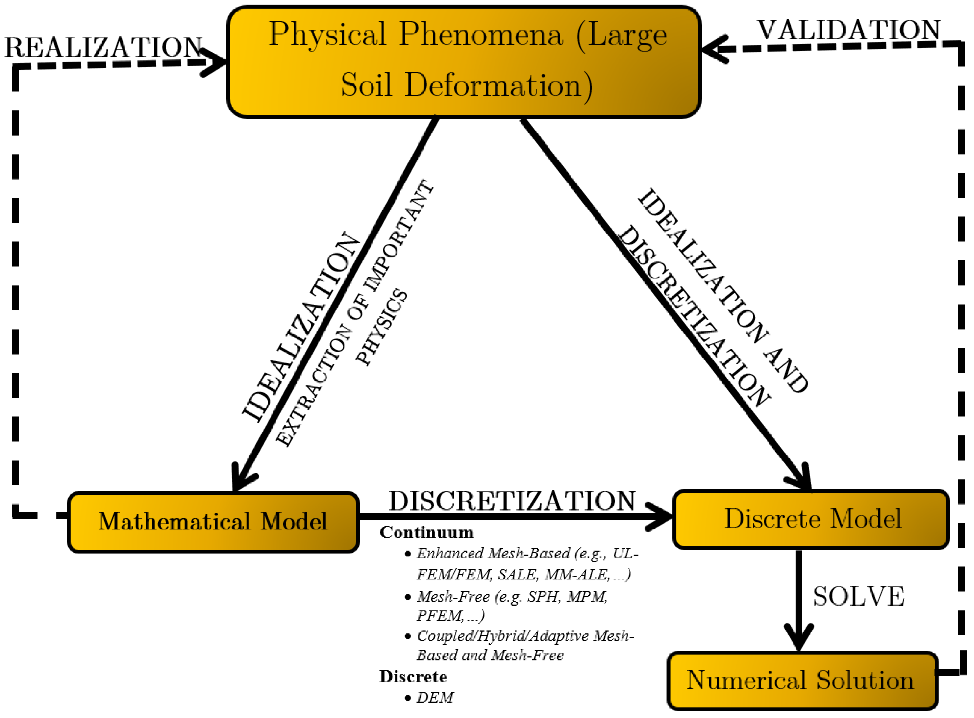
Figure 1. Schematic representation of the computational modeling process for large deformation in granular soils.
Geotechnics 05 00040 g001
Figure 2. MASH strong soil grain sizes from 19.05 mm to silt size. Sieve sizes (19.05 mm, 9.50 mm, 4.75 mm, 2.00 mm, 0.425 mm, and 0.075 mm) are for illustration only; ASTM D6913 recommends a halving pattern for gradation analysis.
Geotechnics 05 00040 g002aGeotechnics 05 00040 g002b
Figure 3. MASH strong soil behavior under static and dynamic impact loading. The left image shows soil behaving as a bulk solid under static loading, while the right image illustrates fluid-like behavior during dynamic impact loading, dominated by inter-particle collisions and momentum exchange [62].
Geotechnics 05 00040 g003
Figure 4. Schematic representation of the Biot hysteretic model [72].
Geotechnics 05 00040 g004
Figure 5. MC failure criterion in the principal stress space with tension cut off (left) and the cross-section of the cut pyramid in the deviatoric plane (right) [87].
Geotechnics 05 00040 g005
Figure 6. Drucker–Prager yield surface in principal stress space and in the π plane [89].
Geotechnics 05 00040 g006
Figure 7. Drucker–Prager yield surface in the J 2 p space [90].
Geotechnics 05 00040 g007
Figure 8. A smooth hyperbolic approximation to the MC yield function in the meridional plane [97].
Geotechnics 05 00040 g008
Figure 9. Yield surface: (a) in deviatoric plane for granular soils and (b) with e = 0.55 [96].
Geotechnics 05 00040 g009
Figure 10. Loading function for the cap model [89].
Geotechnics 05 00040 g010
Figure 11. Shape of Schwer Murray cap model yield surface in three and two dimensions [116].
Geotechnics 05 00040 g011
Figure 12. Illustration of the Hysteretic Soil model: one-dimensional mechanical analog using sliders and springs, along with the cyclic and monotonic shear stress–shear strain response of the four nested surface model [122].
Geotechnics 05 00040 g012
Table 1. Advantages and limitations of LS-DYNA elastic soil models.
ModelAdvantagesLimitations
ElasticConceptually and mathematically simpleDoes not include coupling between deviatoric and volumetric responses, so it cannot simulate dilation during shear deformation.
Requires few material parameters and is easy to calibrateBehavior is incrementally reversible and does not capture yielding or stress-dependent stiffness and strength.
Supported by a wide range of experimental dataInadequate for modeling behavior near failure, and cannot simulate strain softening or strain rate effects
Have been used successfully in many practical applicationsCannot simulate strain-softening as well as strain rate effects
Commonly used in practice for preliminary assessmentsDoes not account for low confinement conditions, which are important in roadside barrier systems involving shallow soil fill
Biot HystereticCapable of simulating hysteretic energy dissipation under cyclic or dynamic loadingCannot represent strain rate effects or strain softening.
Cannot simulate strain rate as well as strain softening effects.
Does not capture yielding or stress-dependent stiffness
Neglects low confinement effects, which are essential in the context of roadside barrier systems embedded in granular soil
Table 2. Advantages and limitations of simple elastoplastic models.
ModelAdvantagesLimitations
Soil and Foam and Soil and Foam FailureRelatively simple to implement when tabulated pressure versus volumetric strain data is availableRequires confinement to maintain numerical stability; developed primarily for high-pressure condition
Material parameters can be calibrated using Mohr–Coulomb cohesion and friction angleUnable to capture volumetric expansion (dilation) of granular soil during shear under impact loading
Does not account for pore pressure build-up or moisture effects during undrained shear failure
Inadequate for modeling strain-softening behavior and strain rate effects
Assumes a circular yield surface in the deviatoric plane, which is inconsistent with experimental observations for granular soils
Pseudo TensorStraightforward to use when yield stress versus pressure data is available in tabulated formNeglects low-confinement effects, which are significant in roadside safety applications
Capable of simulating strain softening and rate-dependent behaviorCannot represent pore pressure build-up or moisture-related effects in undrained dynamic loading
Fails to capture dilative volumetric behavior of soil during impact-driven shear
Table 3. Advantages and limitations of elastoplastic soil models.
ModelAdvantagesLimitations
Drucker–PragerSimple to useExhibits excessive plastic dilation during yielding
Can be calibrated with Mohr–Coulomb parameters by appropriate selection of constantsCannot capture hysteretic stress–strain behavior within the yield surface
Satisfies uniqueness conditions due to associated flow ruleDoes not model pore pressure build-up or moisture effects during undrained shear under dynamic loading
Smooth, continuous yield surface in stress spaceCircular deviatoric section disagrees with experimental data for granular soils
Fails to represent low-confinement effects typical in roadside safety applications
Does not simulate material damage or strain rate effects
Mohr–CoulombSimple to useMay cause numerical instability due to sharp corners in the yield surface
Its validity is well-established for many granular soilsNeglects influence of intermediate principal stress
Hexagonal deviatoric section inconsistent with laboratory results
Does not capture low-confinement behavior characteristic of surface-embedded systems
Cannot model moisture effects or pore pressure generation in undrained shear under impact conditions
Table 4. Advantages and limitations of FHWA soil model.
AdvantagesLimitations
Captures low confinement behavior in granular backfillRequires intensive parameter calibration
Incorporates strain-softening and strain rate effectsRequires detailed experimental data
Accurately reflects deviatoric yield shape evolution
Constructed for simulating soil behavior in roadside barrier systems
Table 5. Advantages and limitations of cap soil models.
ModelAdvantagesLimitations
Geologic CapCan simulate low confinement effects, which is critical in most roadside safety applicationsCannot predict moisture or pore-pressure build-up during undrained failure under dynamic shear loading
Satisfies the theoretical requirements of uniqueness, stability, and continuityDoes not account for strain-softening or damage and strain rate effects
Provides proper control of dilatancyTwo-invariant formulation; cannot simulate lower strength in triaxial extension
Non-smooth yield surface behavior at very low shear stresses causes the algorithm to be complex and inefficient
Schwer Murray CapAccounts for strain-softening or damage and strain rate effectsRelatively complicated model with more than 25 input parameters
Can simulate low confinement effects, which is critical in roadside safety applicationsRelatively complicated model with more than 25 input parameters
Three-invariant formulation; can simulate lower strength in triaxial extensionCannot predict moisture or pore-pressure build-up during undrained failure under dynamic shear loading
Smooth yield surface behavior at very low shear stresses; suitable for finite element implementations
Table 6. Advantages and limitations of the Hysteretic Soil model.
AdvantagesLimitations
Can reproduce the hysteretic response within the failure surfaceCannot simulate moisture or pore-pressure build-up during undrained dynamic shear loading
Accounts for dilatancy and strain rate effectsDoes not incorporate strain-softening or continuum damage
Cannot accurately simulate low-confinement behavior, which is critical in many roadside safety applications
Requires extensive soil characterization to calibrate more than 20 input parameters
Table 7. LS-DYNA soil constitutive models, their attributes, and theoretical formulations.
Type of Soil ModelSoil ModelType of SoilFailure SurfaceFlow Rule: Associated or Non-associatedHardening Criteria
GranularCohesiveRock
ElasticElasticYesYesYesNANANA
Biot HystereticYesYesYesNANANA
Simple ElastoplasticSoil and FoamYesYesYesExtended von MisesAssociatedNone
Soil and Foam FailureYesYesYesExtended von MisesAssociatedNone
Pseudo TensorYesYesYesExtended von MisesAssociatedNone
ElastoplasticSoil ConcreteYesYesYesExtended von MisesAssociatedNone
Mohr–CoulombYesYesYesMohr–CoulombNon-associatedNone
Drucker–PragerYesYesYesExtended von MisesNon-associatedNone
Jointed RockNoNoYesMohr–CoulombNon-associatedNone
Elasto-viscoplasticFHWAYesYesYesModified Mohr–CoulombAssociatedIsotropic
CapGeologic CapYesYesYesCurved extended von MisesAssociatedIsotropic
Schwer Murray CapYesYesYesCurved extended von MisesNon-associatedKinematic
Nested surfaceHystereticYesYesYesExtended von MisesNon-associatedNested surfaces
Soil BrickNoYesNoExtended von MisesAssociatedNested surfaces
Table 8. Evaluation of LS-DYNA soil constitutive models for simulating granular soil behavior under impact loading.
Soil ModelDoes Model Include/PredictModel Group
Three-Dimensional BehaviorLow Confinement EffectsDilationStrain SofteningStrain rate EffectsMoisture/Pore pressure
ElasticYesNoNoNoNoNoFoundational Yield Model
Biot HystereticYesNoNoNoNoNoFoundational Yield Model
Soil and FoamYesNoNoNoNoNoFoundational Yield Model
Soil and Foam FailureYesNoNoNoNoNoFoundational Yield Model
Pseudo TensorYesNoNoYesYesNoIntermediate Capability Model
Soil ConcreteYesNoNoYesNoNoFoundational Yield Model
Mohr–CoulombYesNoYesNoNoNoFoundational Yield Model
Drucker–PragerYesNoYesNoNoNoFoundational Yield Model
Jointed RockYesNoYesNoNoNoFoundational Yield Model
FHWAYesYesYesYesYesYesComprehensive Constitutive Model
Geologic CapYesYesYesNoNoNoIntermediate Capability Model
Schwer Murray CapYesYesYesYesYesNoIntermediate Capability Model
Hysteretic SoilYesNoYesNoYesNoIntermediate Capability Model
Soil BrickYesNoNoNoNoNoFoundational Yield Model
Disclaimer/Publisher’s Note: The statements, opinions and data contained in all publications are solely those of the individual author(s) and contributor(s) and not of MDPI and/or the editor(s). MDPI and/or the editor(s) disclaim responsibility for any injury to people or property resulting from any ideas, methods, instructions or products referred to in the content.