1. Introduction
Centrifuge testing provides a means to examine the in situ behavior of geo-systems within a laboratory environment, an artifact that encapsulates the complexity of natural systems reproducing it in monitored environments [
1]. By using scaled physical models subjected to elevated centrifugal acceleration, centrifuge testing preserves the stress-dependent and nonlinear behavior characteristic of natural soils. This concept has been acknowledged since as early as 1869 [
2], when it was recognized that body weight stresses significantly influence model responses. In contrast to centrifuge models, scaled models under normal gravity fail to replicate the prototype stress conditions—especially for pressure-dependent materials like soil. Soil behavior varies with stress state, shifting from contractive to dilative responses depending on proximity to the critical state. Thus, gravity-based models often exhibit unrealistically dilative behavior compared to field conditions. Centrifuge modeling overcomes this by reproducing prototype stress levels through increased acceleration.
This ability to accurately simulate field stress conditions has driven the global development of advanced centrifuge facilities [
3,
4,
5,
6]. These facilities now support experiments with high centrifugal accelerations and large payload capacities (e.g., 1900 g-ton at the Centrifugal Hypergravity and Interdisciplinary Experiment Facility, Hangzhou, China), enabling investigation of complex geotechnical problems. Early experiments focused on monotonic loading conditions—such as bearing capacity, retaining wall behavior, and slope stability [
7,
8]. Over time, research has expanded to include dynamic soil response, seepage, contaminant transport, and cold region effects [
9,
10,
11,
12].
Centrifuge modeling is governed by scaling laws that vary with the problem type. For example, time scaling differs between long-term processes like consolidation and short-duration dynamic problems like seismic site response [
10]. To validate these laws, researchers employ “modeling of models” experiments [
2,
7,
13,
14,
15], where prototypes are tested at multiple scales and responses are compared. While these studies generally support the validity of scaling laws, they also reveal variability between results, especially across different facilities [
13,
14]. This variability stems from differences in sample preparation (e.g., achieved density, fabric), base motion control, and notably, the effect of centrifugal acceleration itself.
Centrifugal acceleration introduces a radial acceleration field with both vertical and horizontal components, in contrast to the uniform vertical gravitational field. Its magnitude and direction vary with radial distance from the centrifuge axis, which affects the stress distribution within the model. While longer arms reduce this gradient, the non-uniformity remains, especially in larger-scale models. These differences in acceleration fields lead to discrepancies in soil stress states and influence overall behavior. As noted by Tobita et al. [
16], the direct impact of centrifugal acceleration has rarely been isolated or systematically investigated. Their study using curved and planar surfaces in LEAP-2015 experiments offered partial insight but struggled with repeatability due to geometric and base motion inconsistencies, resulting in variations in excess pore pressure and displacement.
A major challenge in understanding the effect of centrifugal acceleration lies in separating it from other sources of experimental variability. Collaborative projects like VELACS and LEAP have shown that differences in sample preparation and base input significantly affect experimental outcomes [
10,
13,
14]. Studies using stochastic analysis [
17,
18,
19] have demonstrated that small variations in density or base excitation can cause large differences in deformation, complicating efforts to isolate the role of centrifugal acceleration.
Numerical modeling offers a valuable means of addressing this issue. Modern finite element and finite difference methods, coupled with advanced constitutive models, have improved significantly in capturing soil behavior. In the 2015 and 2017 phases of LEAP, simulations using small and large strain formulations and bounding-surface plasticity models showed strong potential for accurate predictions when properly calibrated [
18,
19]. These improvements make it possible to explore phenomena that are difficult to isolate in physical tests.
This study leverages numerical methods to isolate and examine the effects of centrifugal acceleration on the behavior of liquefiable soils. Using a finite element model and a two-surface plasticity constitutive law for sand [
20], the study incorporates rigorous calibration based on laboratory and centrifuge data from LEAP 2015 and 2017 [
21,
22]. Ottawa F65 sand, the designated soil for LEAP, was characterized through strain- and stress-controlled cyclic triaxial tests to determine its liquefaction resistance.
The numerical investigation compares soil response under gravitational and centrifugal acceleration fields and considers both planar and curved surface geometries. Results are presented in terms of excess pore pressure generation and deformation for different model scales. The study demonstrates how varying acceleration fields influence initial stress states and dynamic behavior, highlighting the effects of scale and surface geometry.
Ultimately, this work aims to provide a clearer understanding of how centrifugal acceleration affects soil performance, independent of other experimental factors. By leveraging calibrated numerical analysis, it provides a suitable framework for interpreting centrifuge results and improving future experimental design. The paper is organized as follows:
Section 1 presents the LEAP centrifuge experiments.
Section 2 outlines the sand constitutive model and calibration process.
Section 3 introduces the finite element model setup, assumptions, and boundary conditions.
Section 4 presents the simulation results, beginning with initial stress comparisons under different acceleration fields, followed by dynamic response results. Finally, key findings are discussed, and conclusions are drawn regarding the effects of centrifugal acceleration.
2. LEAP Centrifuge Experiments
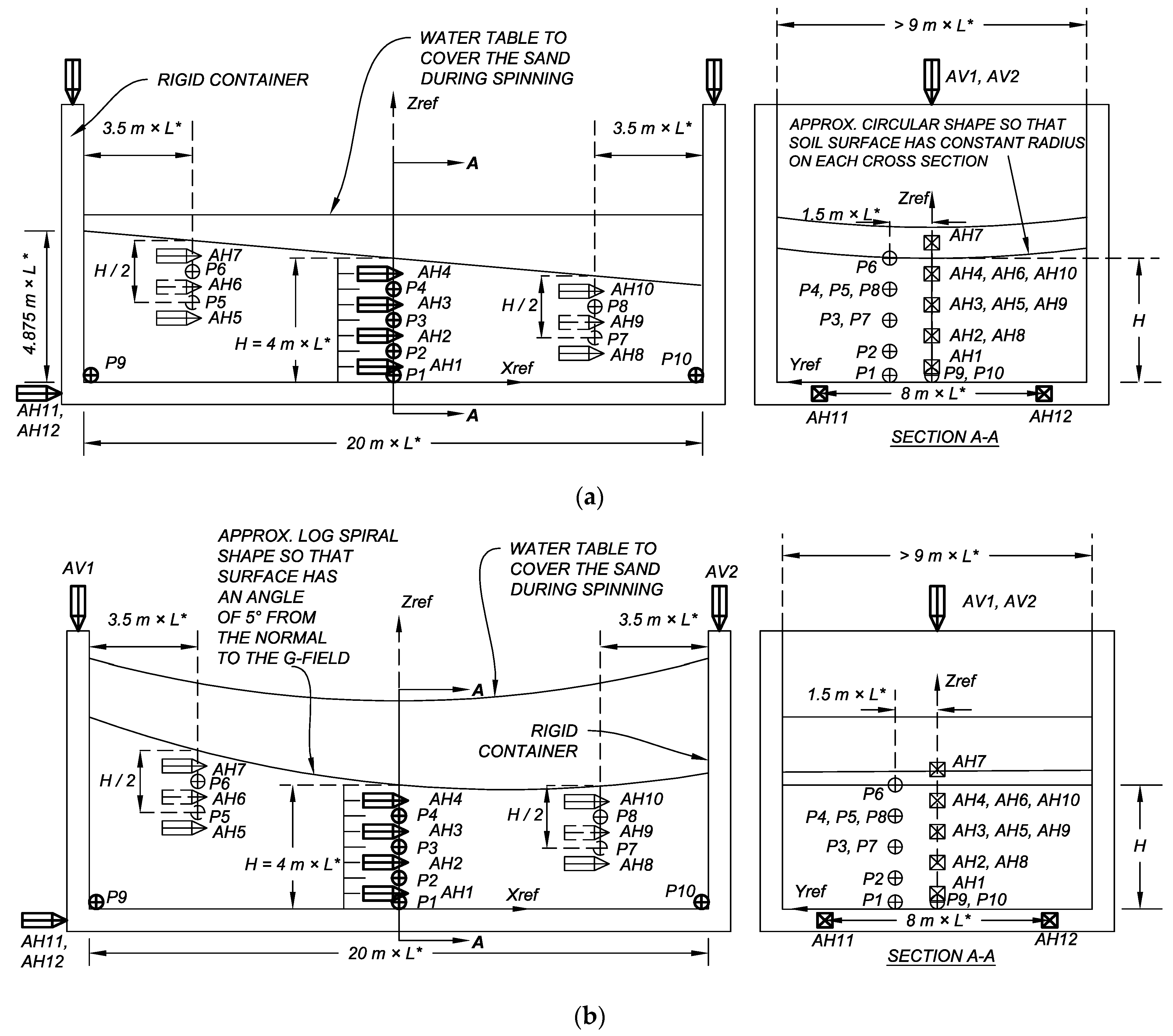
The Liquefaction Experiments and Analysis Project (LEAP) is a joint effort between international research institutes to assess and advance the current state at which the liquefaction phenomenon is modeled physically and analytically. During LEAP-2015 and LEAP-2017, the centrifuge experiments conducted aimed at investigating the seismic response of a mildly sloping ground. A proposed prototype was repeated by six different centrifuge facilities across the globe. The experiment proposed, shown in
Figure 1, is composed of a layer of Ottawa F65 sand with a surface slope of 5 degrees.
The soil specimen has a height of 4.0 m at the center, while the length and the width were 20 and at least 9 m, respectively, in the prototype scale. The soil target density of the soil is 1652 kg/m3. The soil specimen is instrumented using accelerometers (referred to as AH and AV for horizontal and vertical components of the motion) and pore pressure sensors (P1 to P10). Additionally, the soil lateral displacement at the top surface of the test specimen was measured using high-speed cameras monitoring the movements of targets placed on the top surface.
The target base motion the LEAP-2015 experiments is composed of a ramped sinusoidal motion (
Figure 2). The same motion is used in two main events with a frequency of 1 Hz and peak amplitudes of 0.15 and 0.25 g.
The LEAP experiments were performed by several centrifuge facilities as is discussed by Kutter et al. [
13,
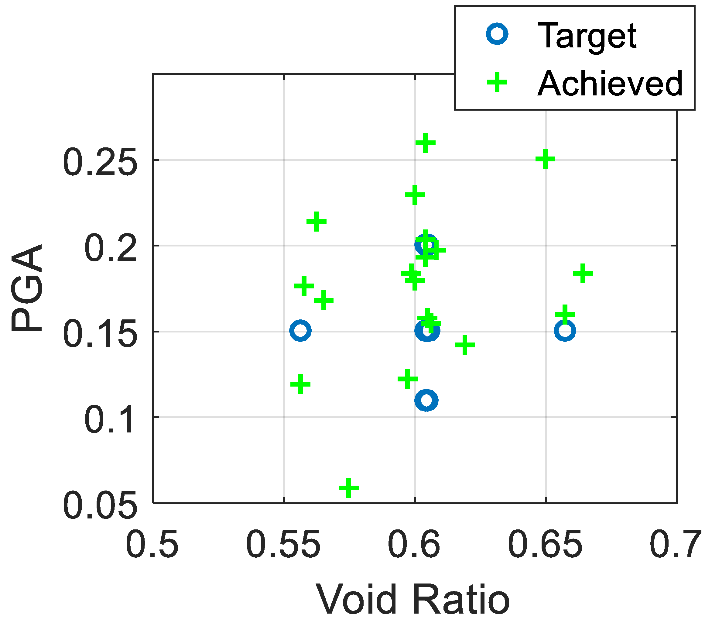
14]. As for the LEAP-2017, larger sets of experiments were conducted covering various densities and peak ground accelerations (PGAs).
Figure 3 shows a plot of the target test matrix versus the achieved experiments.
Table 1 lists the centrifuge facilities participating in the LEAP-2015 and LEAP-2017. Each experiment was modeled with different scales to accommodate the capabilities of the centrifuge used. In four of the centrifuge experiments conducted in the LEAP-2015 and LEAP-2017 projects, the base motion was applied in the direction parallel to the axis of the centrifuge. For this experiment, the sloped surface is modeled as a flat surface, as shown in
Figure 1a. The remaining three experiments applied the base motion in the direction perpendicular to the axis of the centrifuge. To accommodate the radial nature of the centrifugal acceleration, a curved surface geometry is used to model the sloping ground, as shown in
Figure 1b.
The LEAP-2015 and LEAP-2017 projects made two major contributions to the study of soil liquefaction. First, they generated a comprehensive experimental dataset by testing soil specimens under a wide range of initial conditions—including variations in soil density and surface geometry—and subjecting them to diverse seismic inputs with varying intensities and frequency content [
14]. Importantly, the results demonstrated strong repeatability when key parameters such as base motion and initial density were carefully controlled, enhancing confidence in the reliability and quality of the experimental data. Second, the projects provided a rigorous framework for evaluating the predictive capabilities of advanced numerical models through Type-B (blind) simulations [
19]. These comparisons between experimental results and model predictions have directly informed the refinement and validation of state-of-the-art modeling approaches for liquefaction analysis.
3. Numerical Simulation of Centrifuge Experiments
Before proceeding with the study, the numerical analysis tools used should be validated. The validation process is to ensure that the response observed in the experiment can be captured. This process is composed of two steps: constitutive model calibration and finite element simulation of the experiment. This process is summarized in this section; however, for further details on the analyses and results, the reader is referred to Elghoraiby and Manzari [
17].
For the calibration step, the model parameters of the soil constitutive model selected are calibrated to best capture the physical response of the soil. The critical state two-surface plasticity model proposed by Dafalias and Manzari [
20] is selected to model the dynamic behavior of Ottawa F65 sand in the simulations conducted herein. The undrained strain-controlled cyclic triaxial tests by Vasko [
21] are used to calibrate the model. To further validate the model performance at an element level, additional analyses were performed to model the cyclic triaxial tests performed in the LEAP-2017 project [
21,
22].
For the second step of the validation process, the model capability in capturing the observed response of the soil in a boundary value problem setting is achieved through simulation of a centrifuge experiment. For the analyses presented in this study, the numerical simulations are performed using OpenSEES platform [
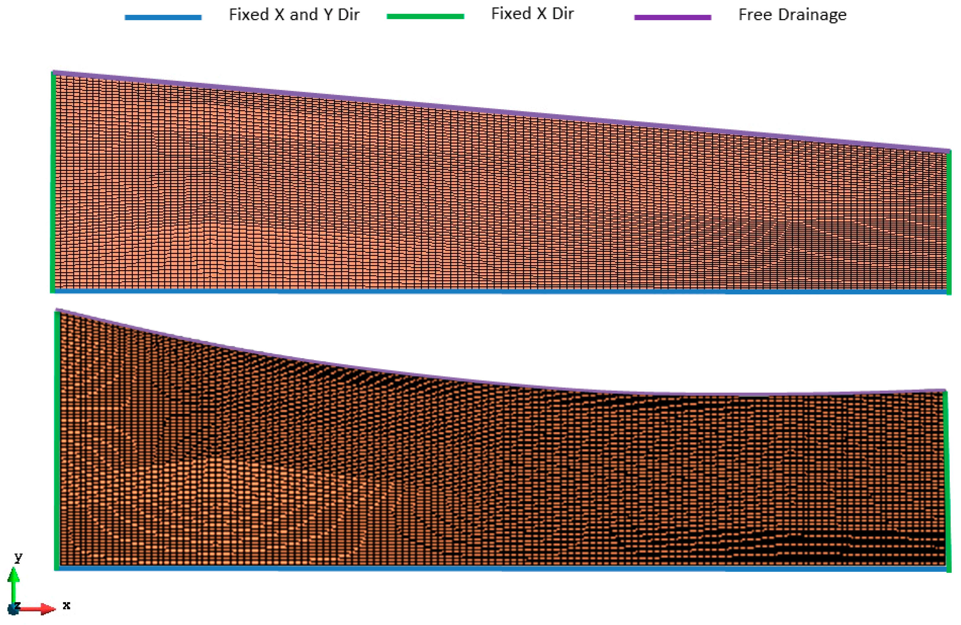
23]. The soil is modeled using hydro-mechanically coupled four-node quadrilateral elements to ensure a fully coupled analysis capable of producing displacements and pore pressure at the nodes. To evaluate the convergence of the finite element model, four different mesh densities are considered ranging from 128 elements (8 vertical × 16 horizontal) to 8192 elements (64 vertical × 128 horizontal). Elghoraiby and Manzari [
17] have shown that the errors in x and y displacements for a finite element mesh with 2048 elements are less than 1 percent.
Figure 4 shows the finite element models (8192 elements) used in the study presented herein along with the model boundary conditions. As highlighted in the figure, the lateral and vertical displacements are assumed to be zero at the base. The nodes on the two sides are fixed laterally but are free in the vertical direction. The free drainage boundary condition was used on the top surface. Before subjecting the model to seismic loading, a gravity stage is simulated to generate the initial stresses caused by centrifugal accelerations. To achieve a steady state for gravity-induced stresses and pore pressures within the soil specimen, the initial analysis must be allowed to run for sufficient time.
After obtaining a converged solution, the next step is to check whether the calibrated model could capture the observed response in the experiment. The experiment modeled in this study is the one performed at RPI during LEAP 2015 [
24,
25]. In the study presented by ElGhoraiby and Manzari [
17], it was shown that the finite element model was able to reasonably capture the magnitude of the lateral spreading, as was presented in the displacement–time history, as well as the excess pore water pressure development.
4. Effects of Centrifugal Acceleration and Curved Surface Geometry
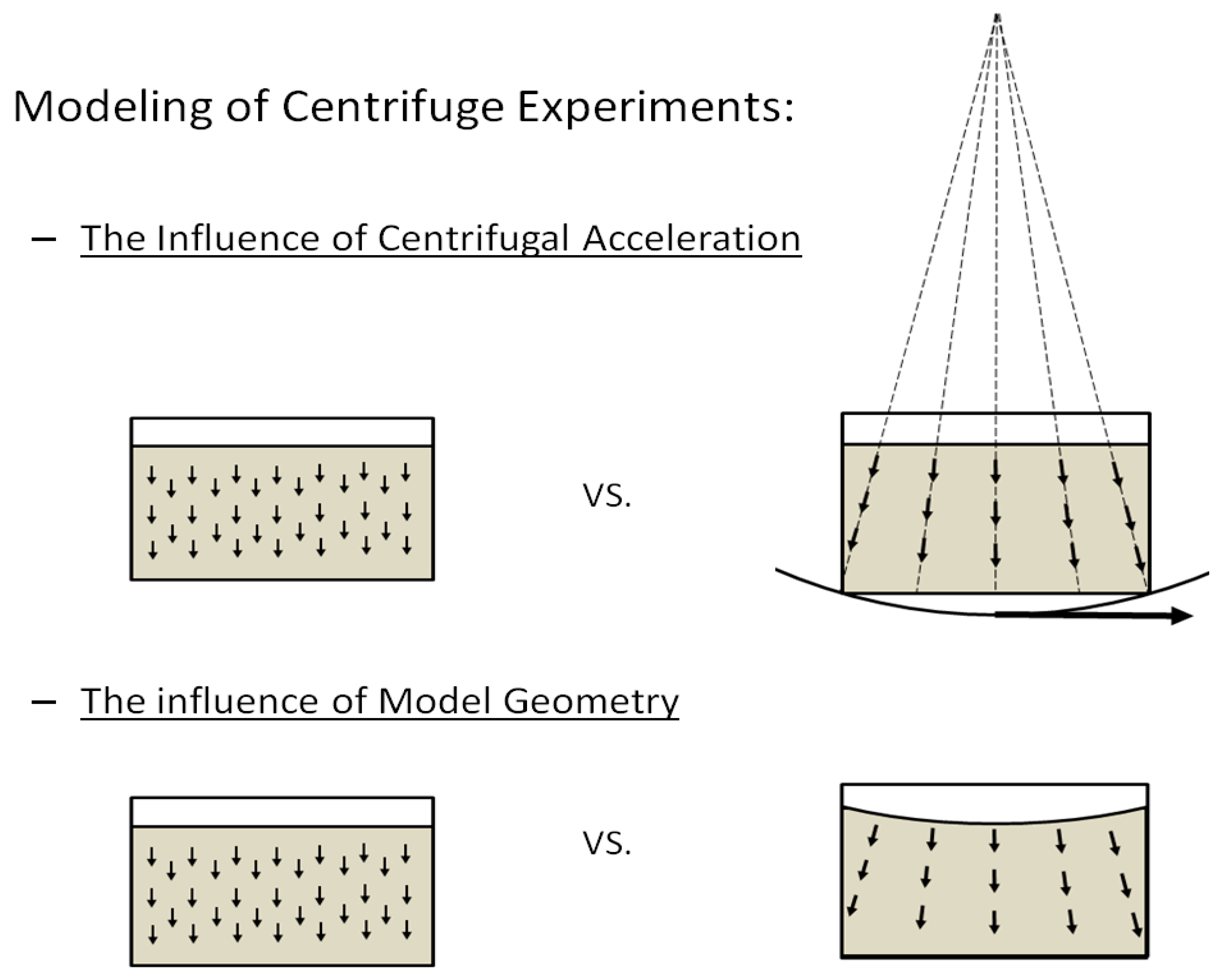
After showing that the available numerical analysis tools can provide a decent prediction of the centrifuge experiment, the analysis of the effects of centrifugal acceleration and the use of curved surface geometry can proceed. Here, two simulation cases are performed; the first focuses on how the difference between the gravitational acceleration field and the imposed centrifugal acceleration field influences the results of the centrifuge acceleration. The second simulation case focuses on how the stress field is influenced by and the consequences of the use of curved surface geometry that is normal to the radial acceleration field.
Figure 5 shows a schematic drawing of the two types of simulations of interest.
In the performed analyses, we first evaluate the initial state of stress and how it is influenced by the different modeling conditions. Next the response of the models during the dynamic analysis is reviewed. By looking at the development of the excess porewater pressure and the initial state of stress, the response of the soil could be further explained. Finally, the response of the soil in terms of deformation is assessed. The two simulation cases provide insight into how the two types of analyses influence the lateral spreading and settlement generated as the soil is subjected to the base motion.
4.1. Modeling of the Problem
The two cases previously presented are modeled using the finite element analysis tools used in the simulation of the centrifuge experiment section. The model previously presented is used to model the application of the gravitational acceleration field. For the case where the centrifugal acceleration field is applied to a flat surface, the same model geometry is used following the same discretization. However, in this case the centrifugal acceleration is applied to the elements instead. The acceleration generated by the centrifuge applies both vertical and horizontal components to the element. These components are computed depending on the radius, r, of the centrifuge used and the scale, L, of the model. In the case of the RPI experiment, the centrifuge has a radius of 3.0 m, and the model scale is 23.0. Accordingly, the centrifugal acceleration can be computed as
where
and
stand for the horizontal and vertical components of the centrifugal acceleration, respectively.
stands for the angular velocity of the centrifuge, while
r, Equation (2), is the radius from the center of rotation to the centroid of the element at which the acceleration is computed.
and are the x and y components of the radius of rotation, computed as the difference between the x and y coordinates of the center of rotation and the x and y coordinates of the centroid of the element.
4.2. Initial State of the Soil
In this section, the initial state of stresses present in the soil at the end of the gravity analysis step is evaluated. At the end of this step, stresses due to the gravitational/centrifugal acceleration should reach a steady state before the start of the dynamic step. At this point, the internal variables of the constitutive model should have been properly initialized.
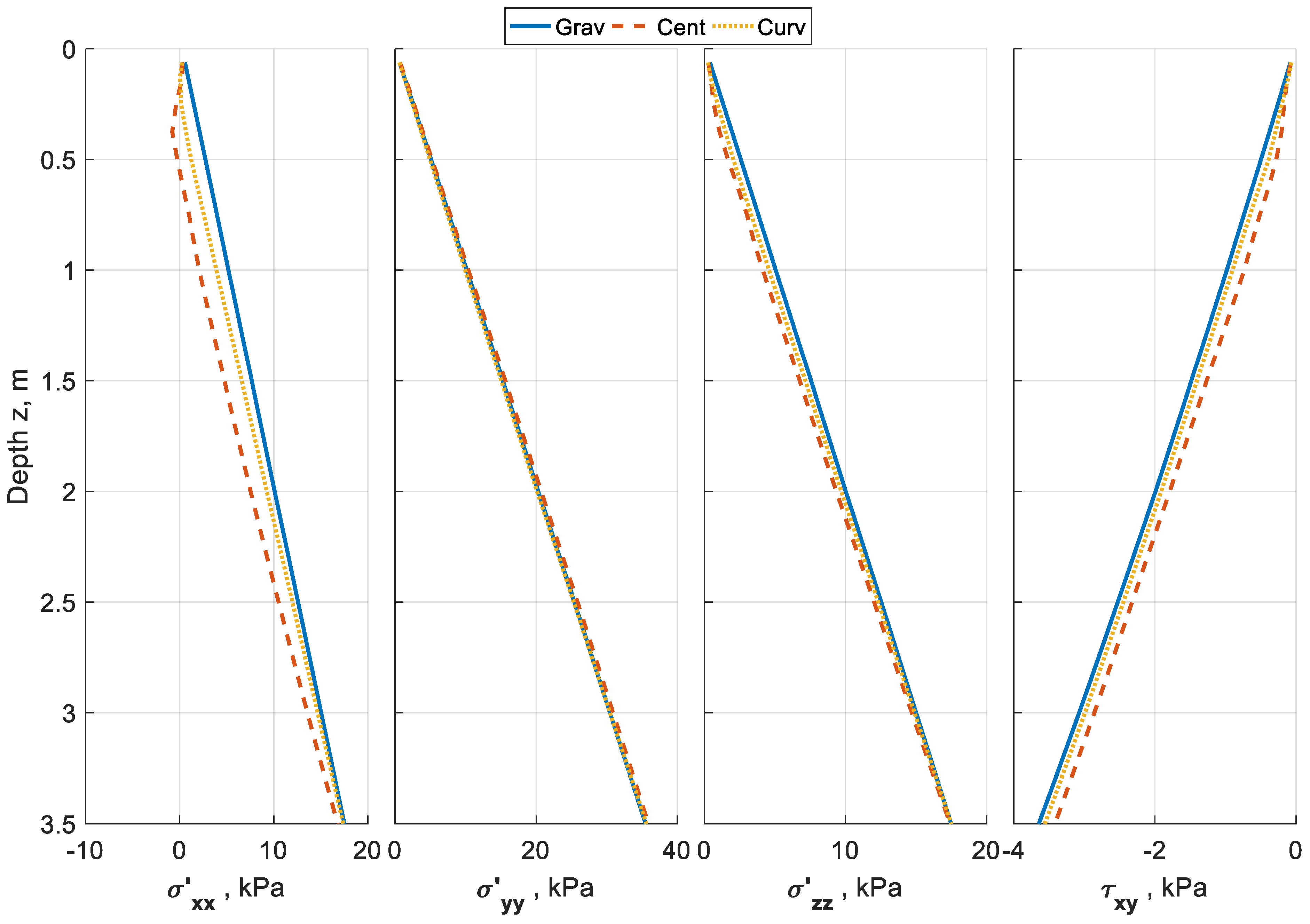
Figure 6,
Figure 7 and
Figure 8 plot the stress distribution at the end of the gravity analysis step. In each figure, the profile distributions of the effective vertical (
σ’yy), effective horizontal (
σ’xx and
σ’zz) and shear (
τyy) stresses are presented. The data plotted compares the state of stress for the gravitational acceleration field, centrifugal acceleration field and curved surface geometry cases.
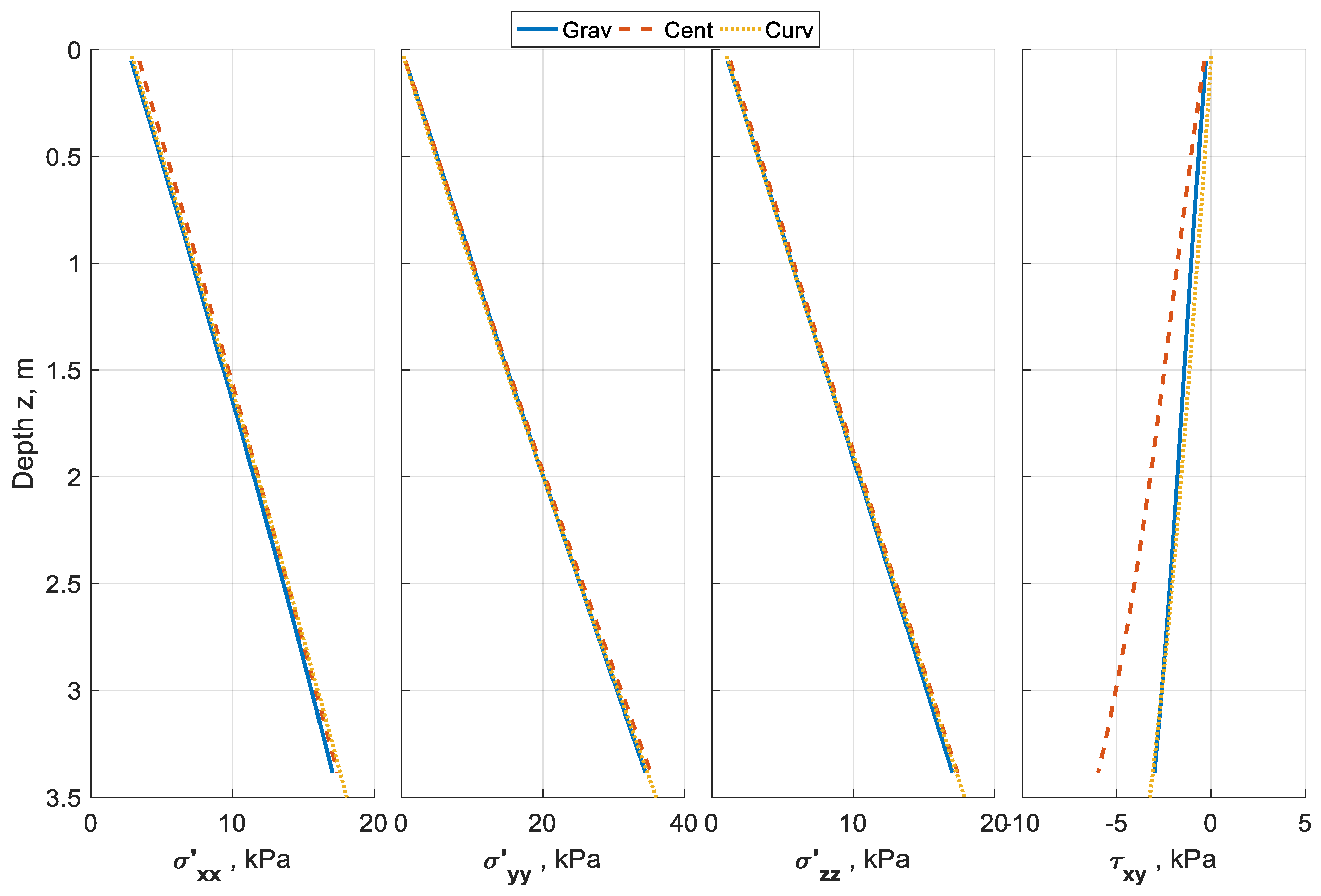
Figure 6 shows the plot of the stresses at the location of the left array of sensors, while
Figure 7 and
Figure 8 present the results at the center and right arrays, respectively. It can be seen from the plots that while the vertical stress is the same for the three simulation cases, differences can be seen in the horizontal and shear stresses. The horizontal components of the centrifugal acceleration resulted in a decrease in the shear stress at the left array because the acceleration acted against the downward slope. The opposite can be observed in the shear stress at the right array where the acceleration component is in the direction of the downward slope. It can also be seen from the figures that the use of curved surface geometry managed to reduce the differences in the shear stresses between the gravitational acceleration and centrifugal acceleration fields.
5. Dynamic Analysis of Centrifugal Acceleration and Curved Surface Geometry
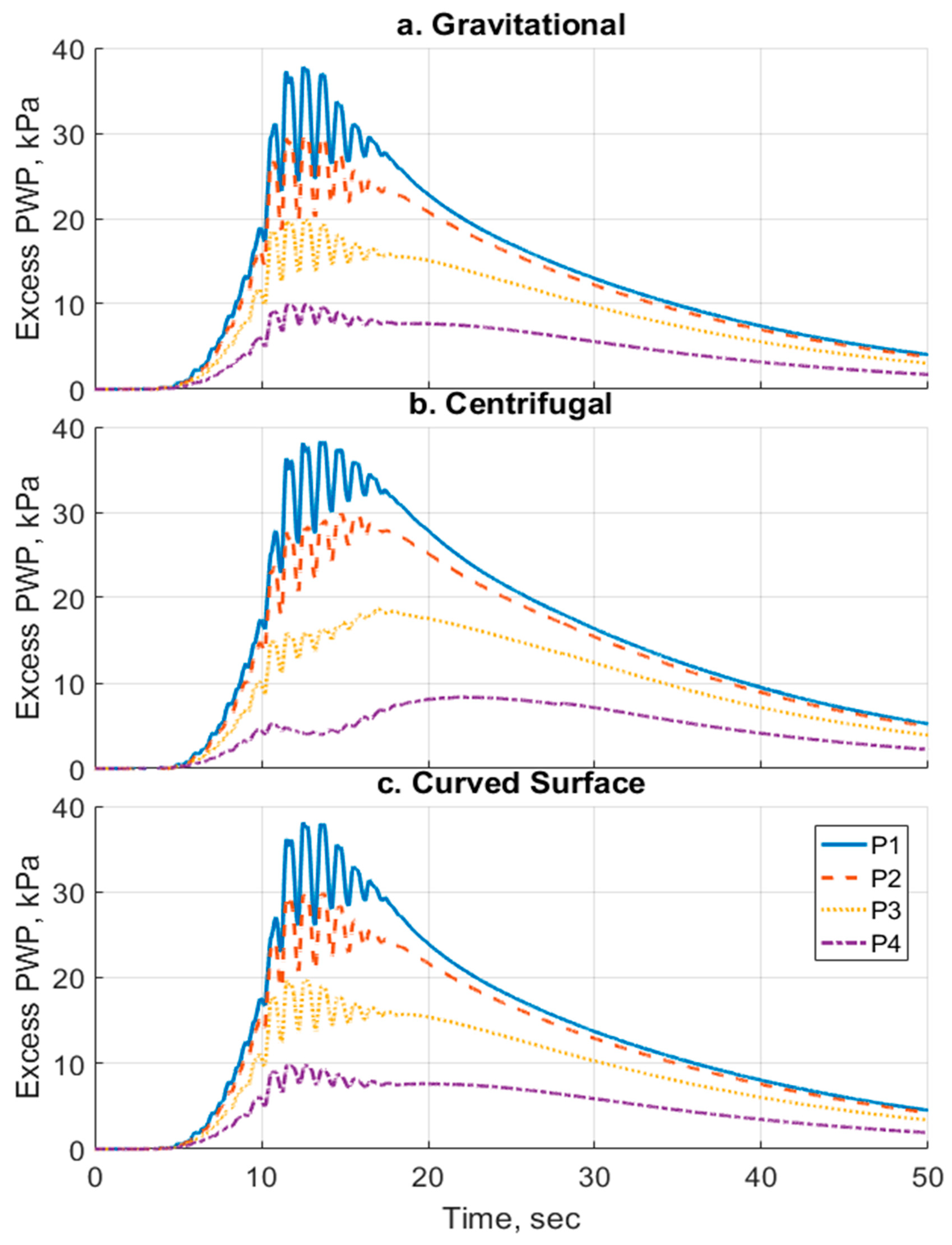
The results of the simulations are presented in this section. The three cases modeled are combined to clearly view the effects of the different acceleration fields and the different model geometries. First, the pore water pressure development is analyzed through plotting the excess pore pressure–time histories.
Figure 9 shows the plots of the excess pore pressure–time histories for the three cases (gravitational, centrifugal and curved surface) at the locations of the pore pressure transducers of the central array (P1–4). The results show a similar trend between the three cases during the generation and dissipation of the excess pore pressure. However, the results vary at the peak of the pore pressure. For the centrifugal case, the soil generates lower excess pore pressures. It can also be seen that the difference between the excess pore pressures generated becomes larger for the locations closer to the surface. For the curved surface case, while the model is still subjected to a centrifugal acceleration field, the soil shows the same response as the gravitational case in terms of excess pore pressure development.
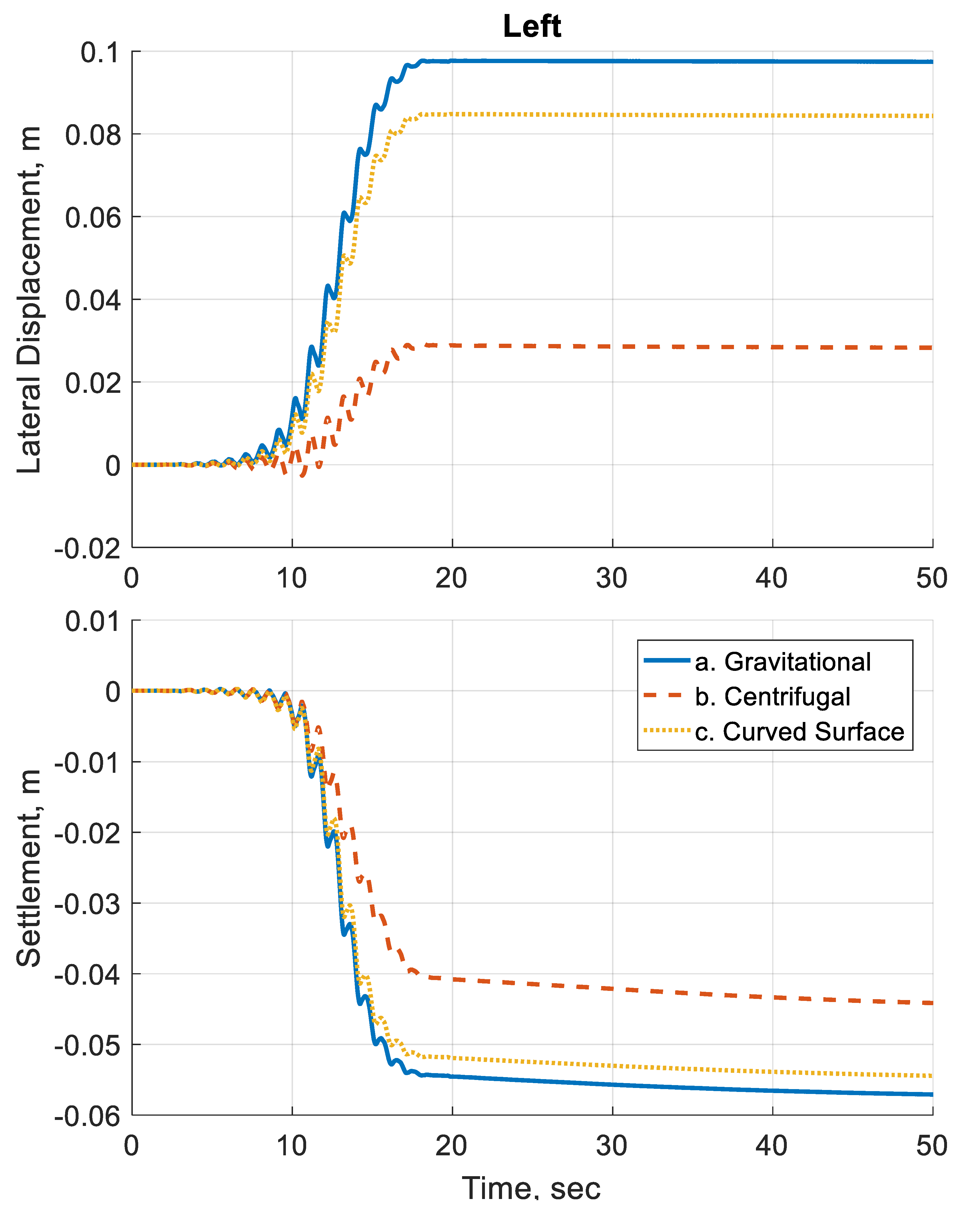
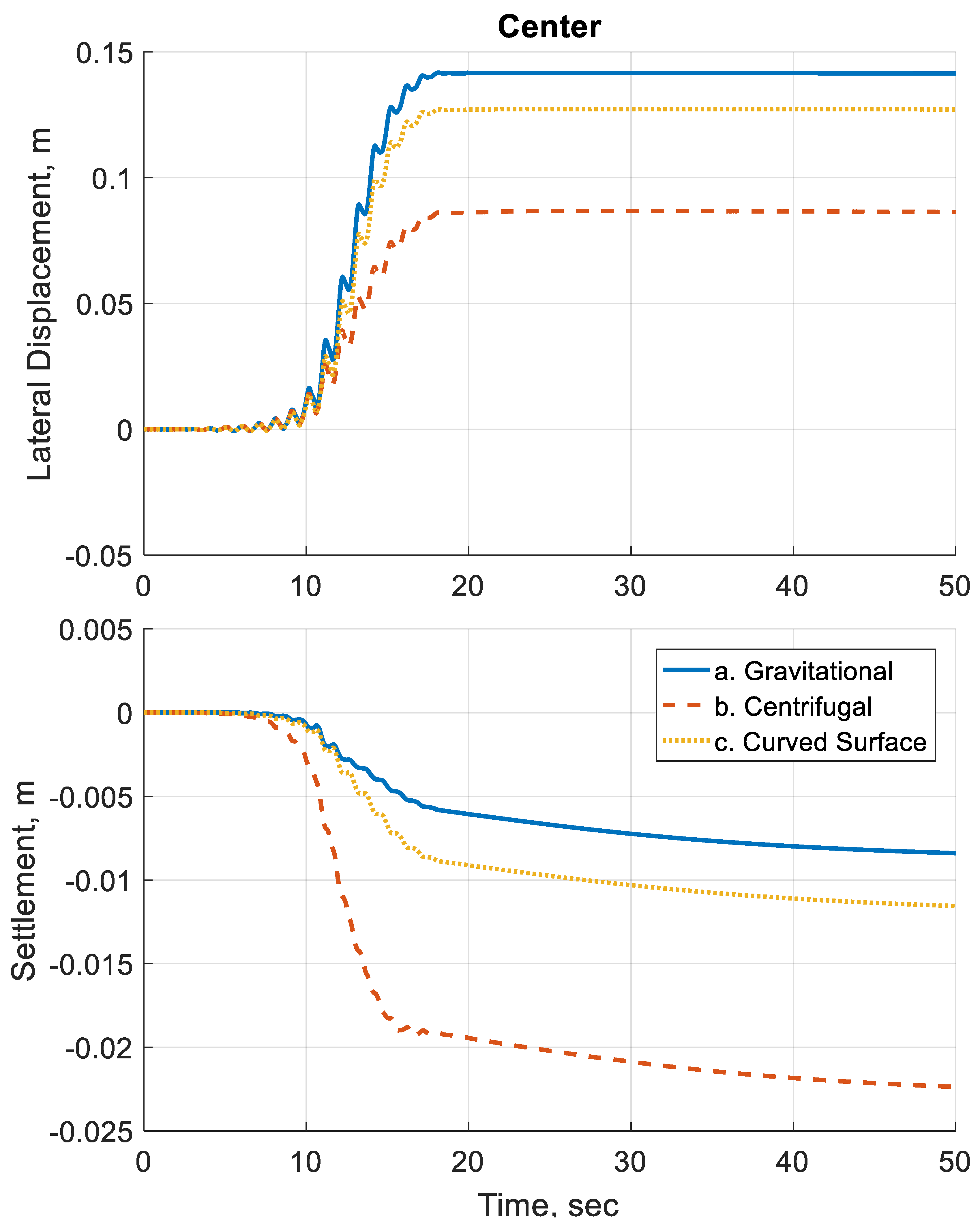
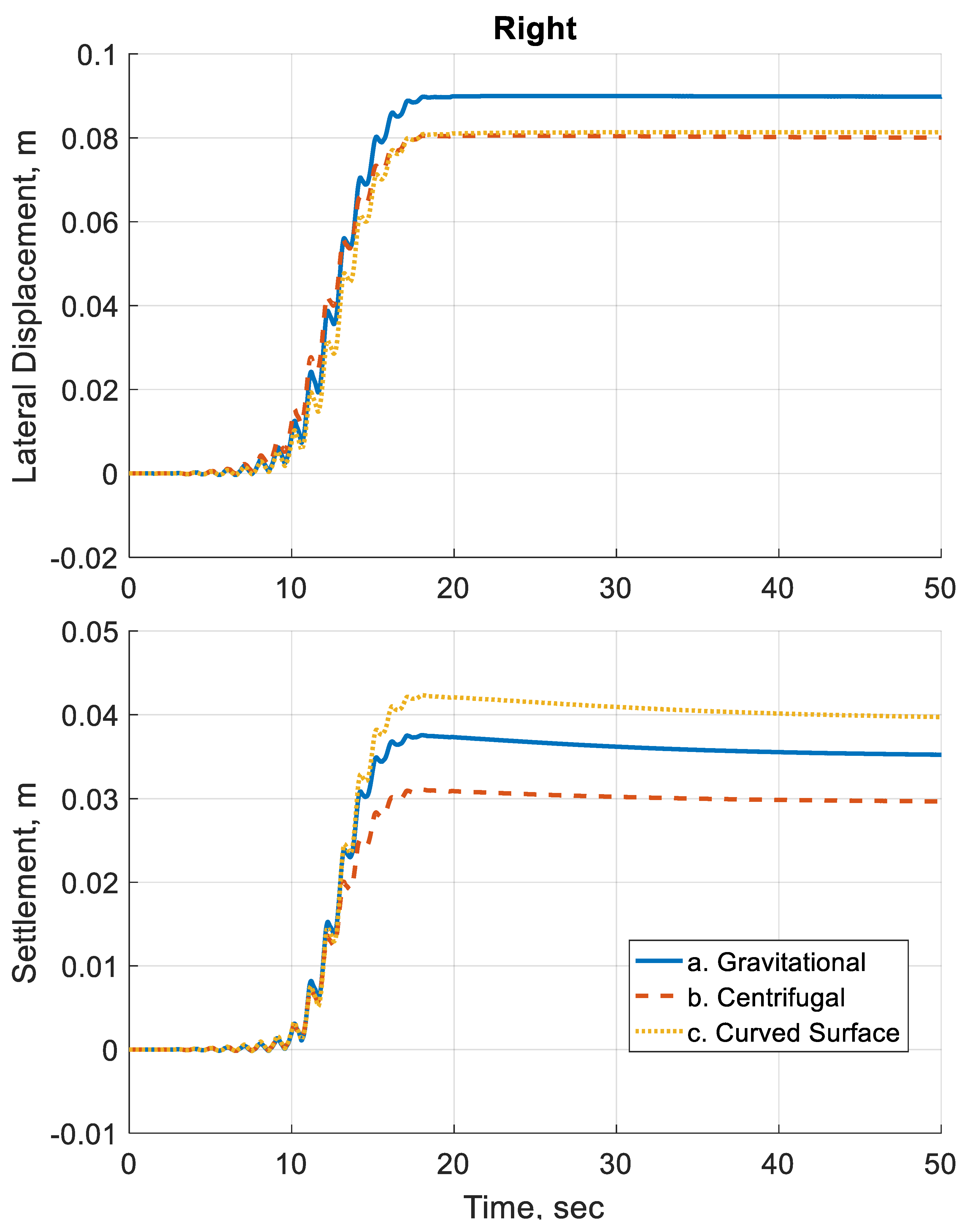
Next, the response of the soil is evaluated through the deformations generated for each case. First the time histories for the soil surface displacements are plotted.
Figure 10 shows the surface settlement and lateral displacement–time histories right above the left array of sensors. Similarly,
Figure 11 and
Figure 12 plot the surface displacement–time histories above the center and right array of sensors, respectively.
Differences can be observed in the displacements between the three simulation cases.
Table 2 summarizes the final displacements obtained from the simulations. The difference in displacements can be as large as 3.5 times between the gravitational case and centrifugal case. The use of curved surface geometry has reduced the difference with the gravitational case.
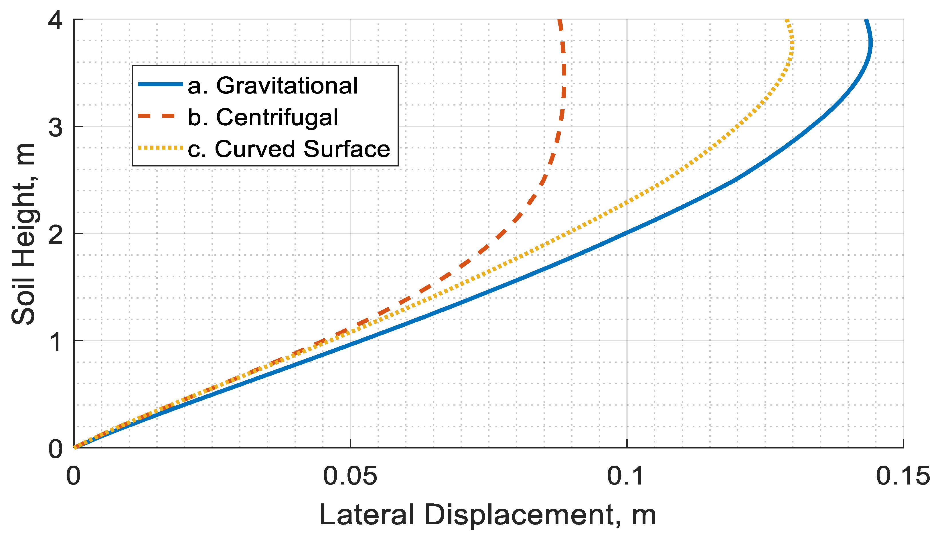
For further understanding of the response of lateral spreading problem, the final lateral displacement of the soil profile at the center is plotted for the three cases in
Figure 13. It can be seen from the figure that two distinct responses exist between the gravitational and centrifugal cases, while the curved surface case shows a transition from the centrifugal case response to the gravitational case response as it gets closer to the surface. This response can be more clearly seen by plotting the slope of the lateral displacement for the soil profile, as is shown in
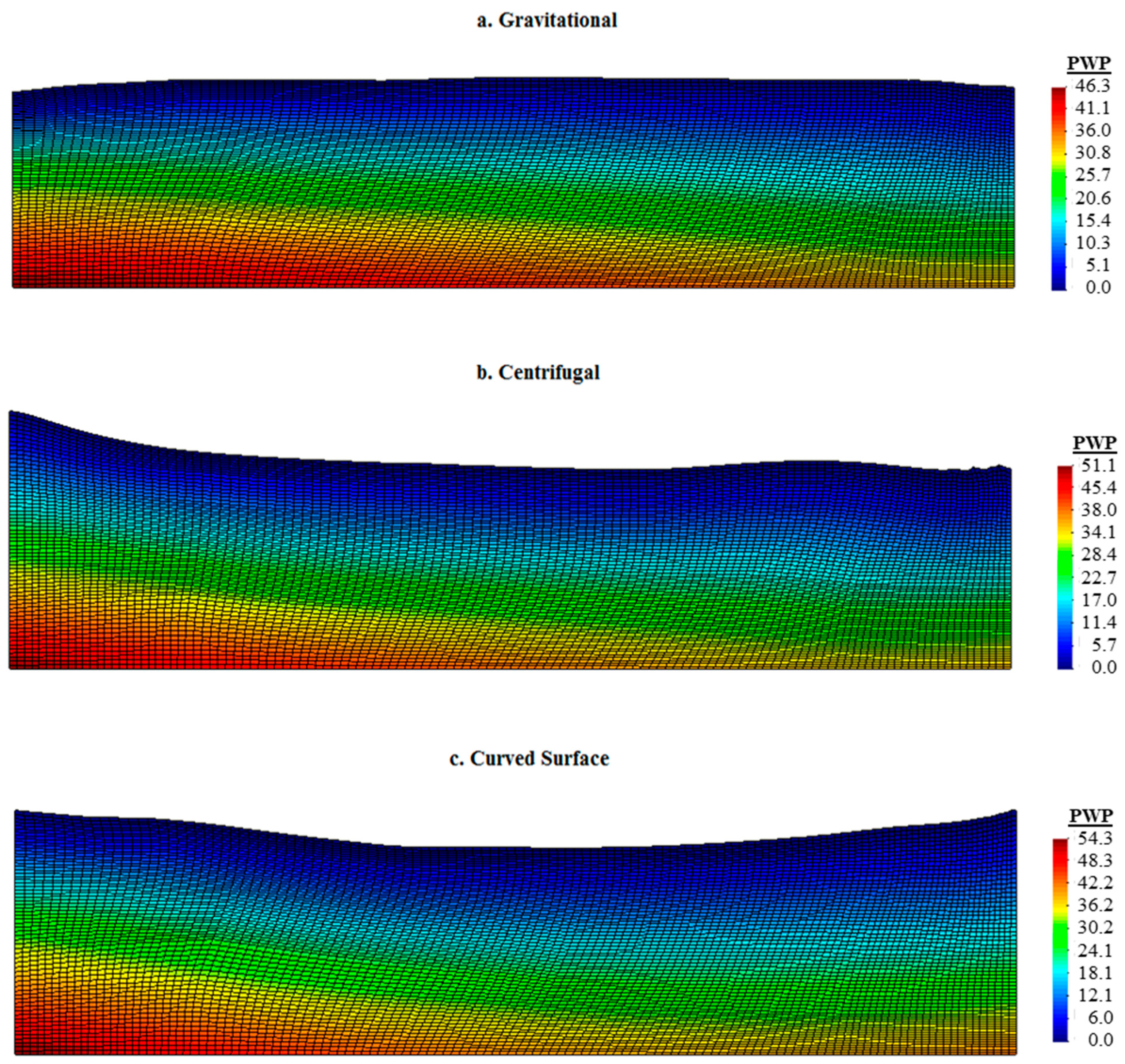
Figure 14. The slopes of the curved surface and centrifugal cases overlapped at the soil base for about 0.5 m. Then, the transition occurred between 0.5 m and 3.0 m for the soil profile height. Then, from 3.0 m up to the soil surface, the curved surface and gravitational cases lateral displacements overlapped. This problem suggests that the soil response is influenced by the boundary conditions, where the base of the curved surface geometry remains flat, which renders the response similar to the centrifugal case. Finally, more insight can be gained by looking at the final deformed shape of the soil for the three cases, as is shown in
Figure 15.
6. Discussion
The main goal of this study is to understand the effects of centrifugal acceleration on the response of centrifuge experiments. Since numerical analysis proved to be the more efficient route for this study, it was necessary to ensure that the numerical tools can provide a convergent solution and can capture the physics observed in the experiment before proceeding with the study. It was shown in the earlier section that a fine mesh was used to ensure the convergence of the solution and reduce the numerical errors. Additionally, a thorough calibration of the constitutive model parameters was conducted, and a good agreement was reached between the simulation and experiment for the generated excess pore pressure and the final displacement. The next step is to proceed with the study and draw observations from the generated results.
First by looking at the excess pore pressure results in
Figure 9, the difference between the responses obtained from the gravitational analysis and those from the centrifugal one indicate that for the centrifugal acceleration case, a lower excess pore pressure is generated. This can be explained by the soil exhibiting a more dilative response than the soil in the gravitational case. The reason for the difference in this behavior could be attributed to the differences in the initial stresses within the soil, as can be seen in
Figure 6,
Figure 7 and
Figure 8. On the other hand, the curved surface geometry case shows that the pore pressure trend matches what is observed in the gravitational case. Similarly, it can be seen that the state of stress is closer to the state of the gravitational case. This clearly shows that a curved surface geometry model provides a better representation of the prototype.
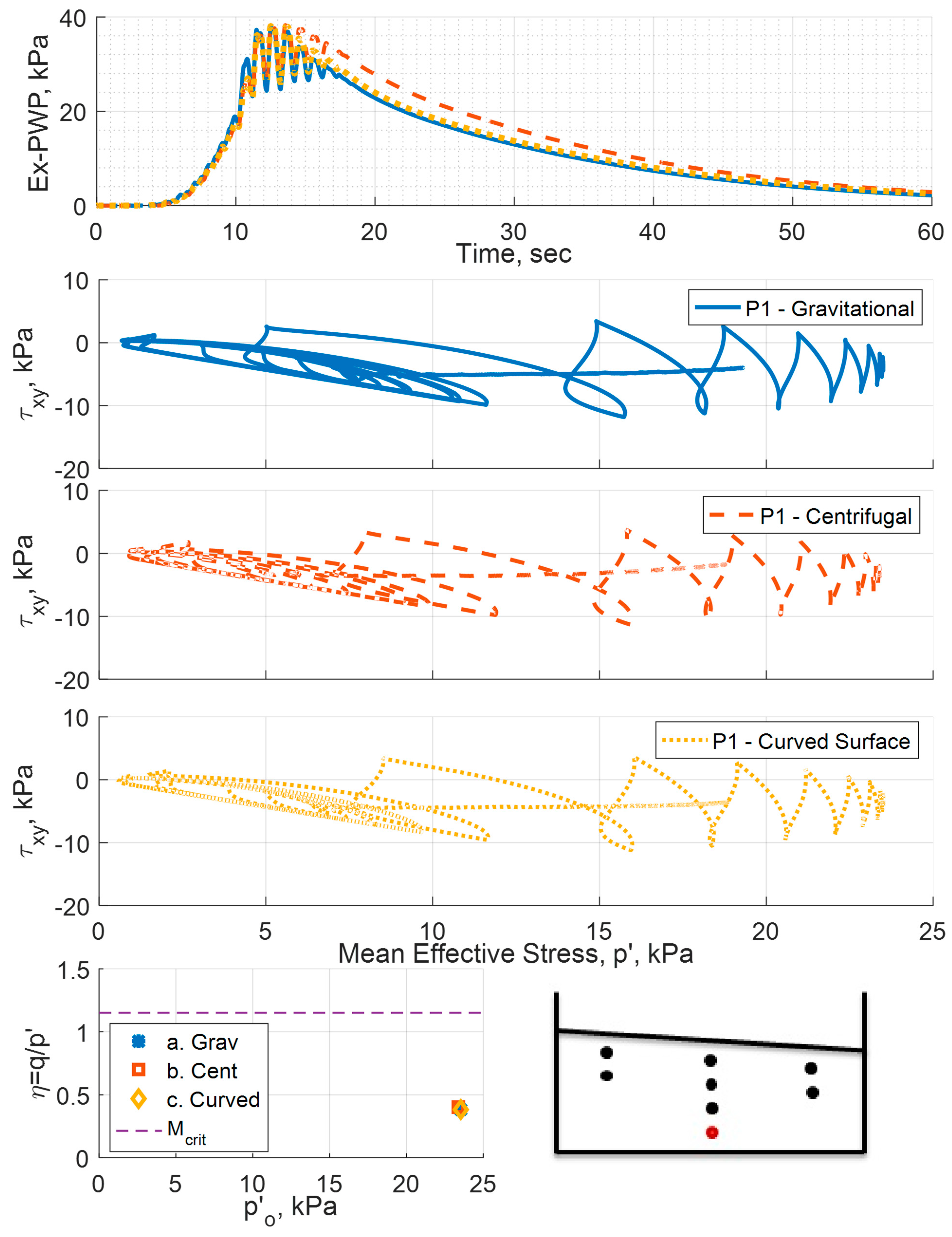
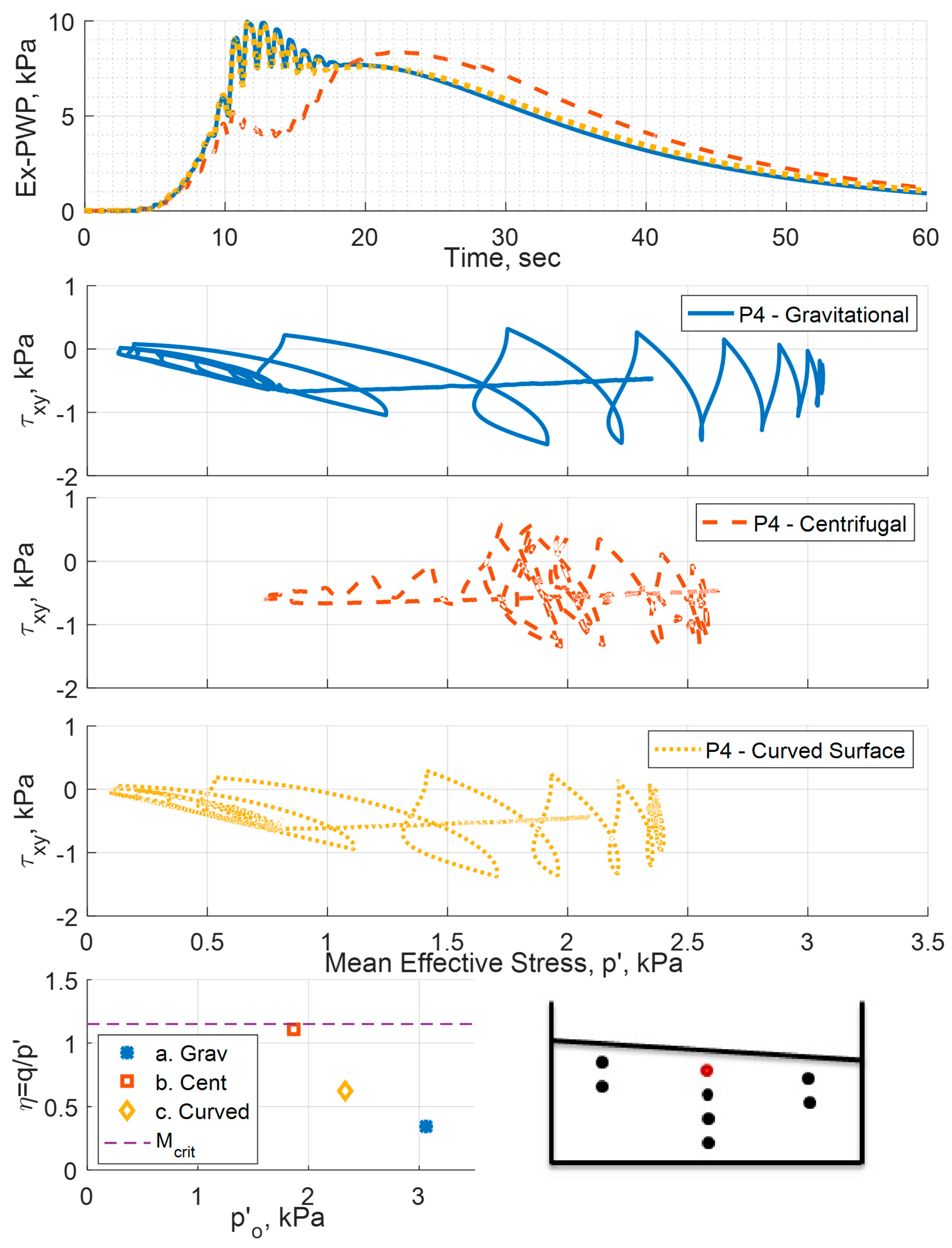
The variations in the generated excess pore water pressure between the three cases can be studied from a different point of view.
Figure 16 and
Figure 17 present the excess pore water pressure at the location of sensors P1 and P4, respectively, along with the initial state of stress in the mean stress p’
o vs. the shear stress ratio η, as well as the effective stress path at this location for each simulation case. The initial shear stress ratio is plotted along with the critical state stress ratio for the Ottawa F65 sand. The initial state of the stress at P1 is more or less the same for gravitation, centrifugal and curved surface geometry cases. Since the state of stress is the same, the effective stress path is similar, and accordingly the generated excess pore pressure is similar. On the other hand, for the P4 case, we can see that the initial state of stress is different for the three cases. The model subjected to the centrifugal acceleration field experiences a shear stress ratio that is very close to the critical state ratio. As a consequence, the model behaved in a more dilative response, resulting in generating less excess pore pressure than the gravitational case. The use of curved surface geometry, on the other hand, resulted in a reduction in the shear stress ratio, which resulted in a more contractive response, generating similar excess pore pressure to the gravitational case.
The displacements generated are also influenced by centrifugal acceleration. It can be seen from the displacement plots that the deformations of the soil are affected by the radial nature of the centrifugal acceleration field. While the results show that the curved surface geometry improved the generated displacements, the results are not the same. This can be attributed to the fact that while the geometric transformation introduced by curving the surface may complement the radial nature of the centrifugal acceleration, the boundary conditions remained the same as the gravitational case, influencing the response of the soil.
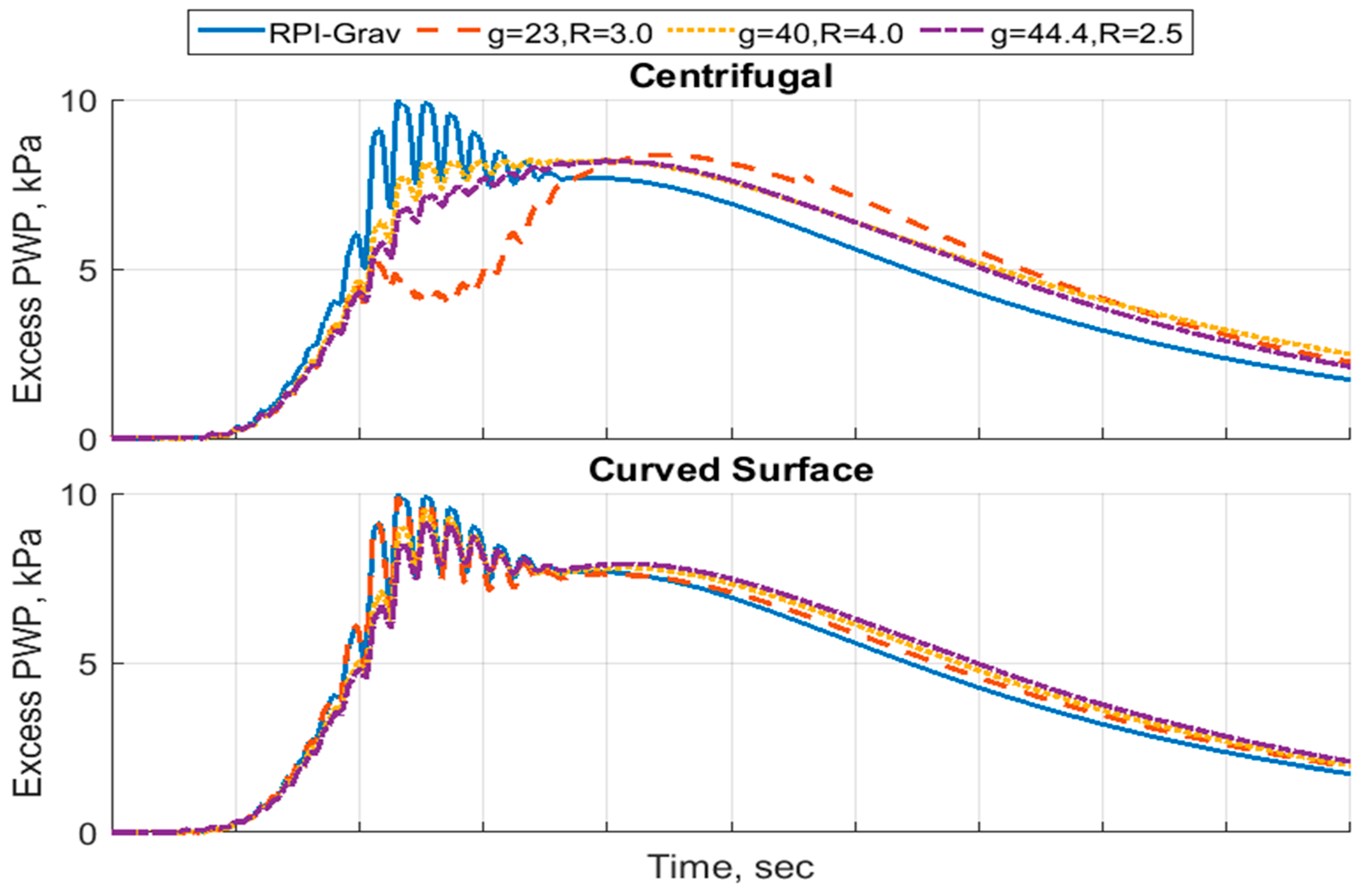
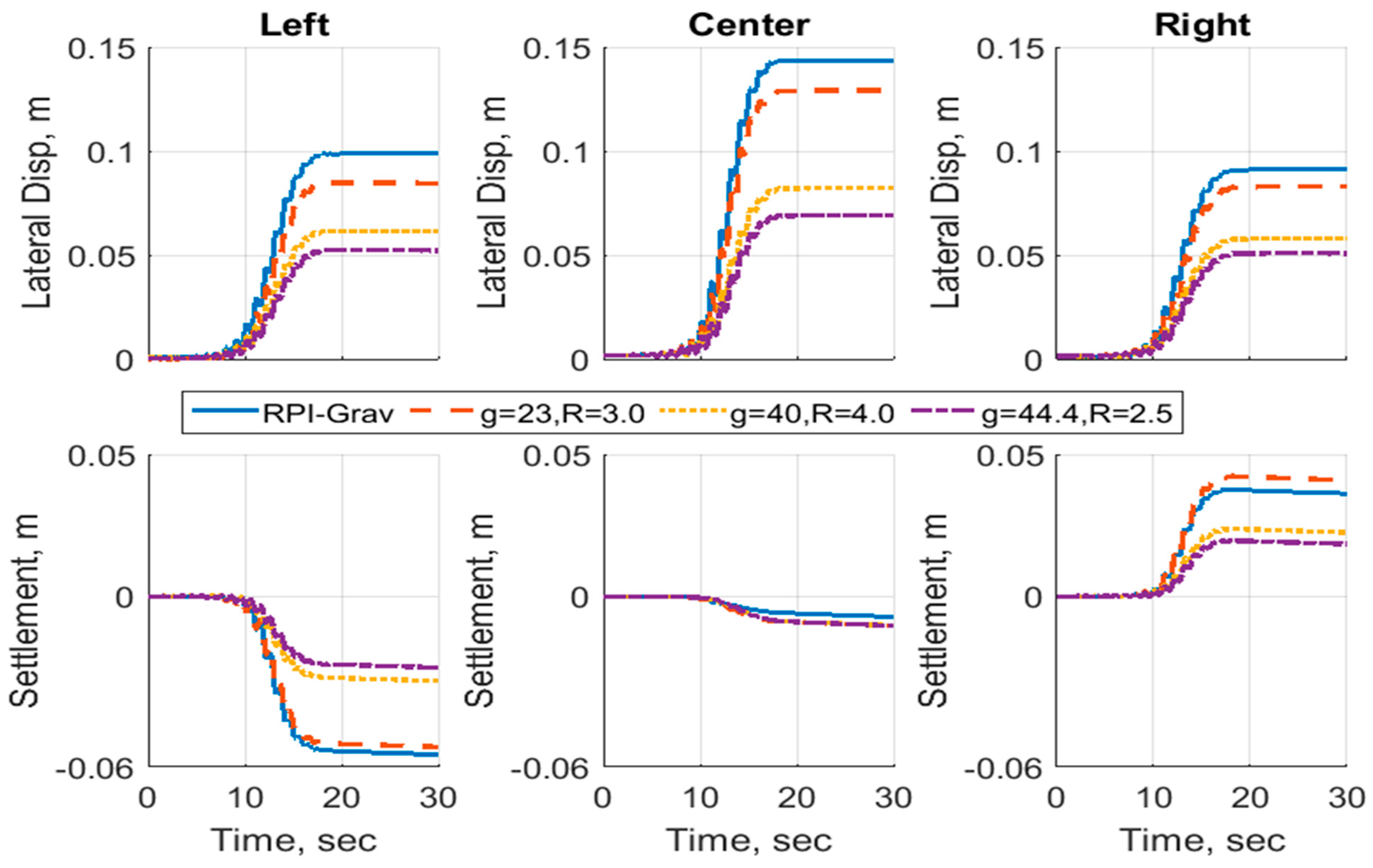
As was presented earlier, the centrifugal acceleration influences the generated excess pore pressure and the soil displacements, and while the use of curved surface geometry improves the development of excess pore pressure and displacements to match the gravitational case, the results do not match identically. Therefore, the question of how the model scale influences the results needs to be addressed. In the LEAP, the experiment was performed by several institutes, where curved surface geometry was used in a few of them at different model scales and radii of rotation. To answer how the model scale affects the response of the soil, three different cases are compared to the results from the gravitational case. The three cases varied in terms of the g Level (23, 40 and 44.4) and the radius of rotation (3.0, 4.0 and 2.5). Both the flat surface and curved surface geometries were modeled.
Figure 18 presents the results of the excess pore pressure development at the location of sensor P4. It can be seen for the centrifugal acceleration case that the model scale significantly influences the response of the generated pore pressure. However, if a curved surface is introduced, the generated excess pore pressures show a similar trend.
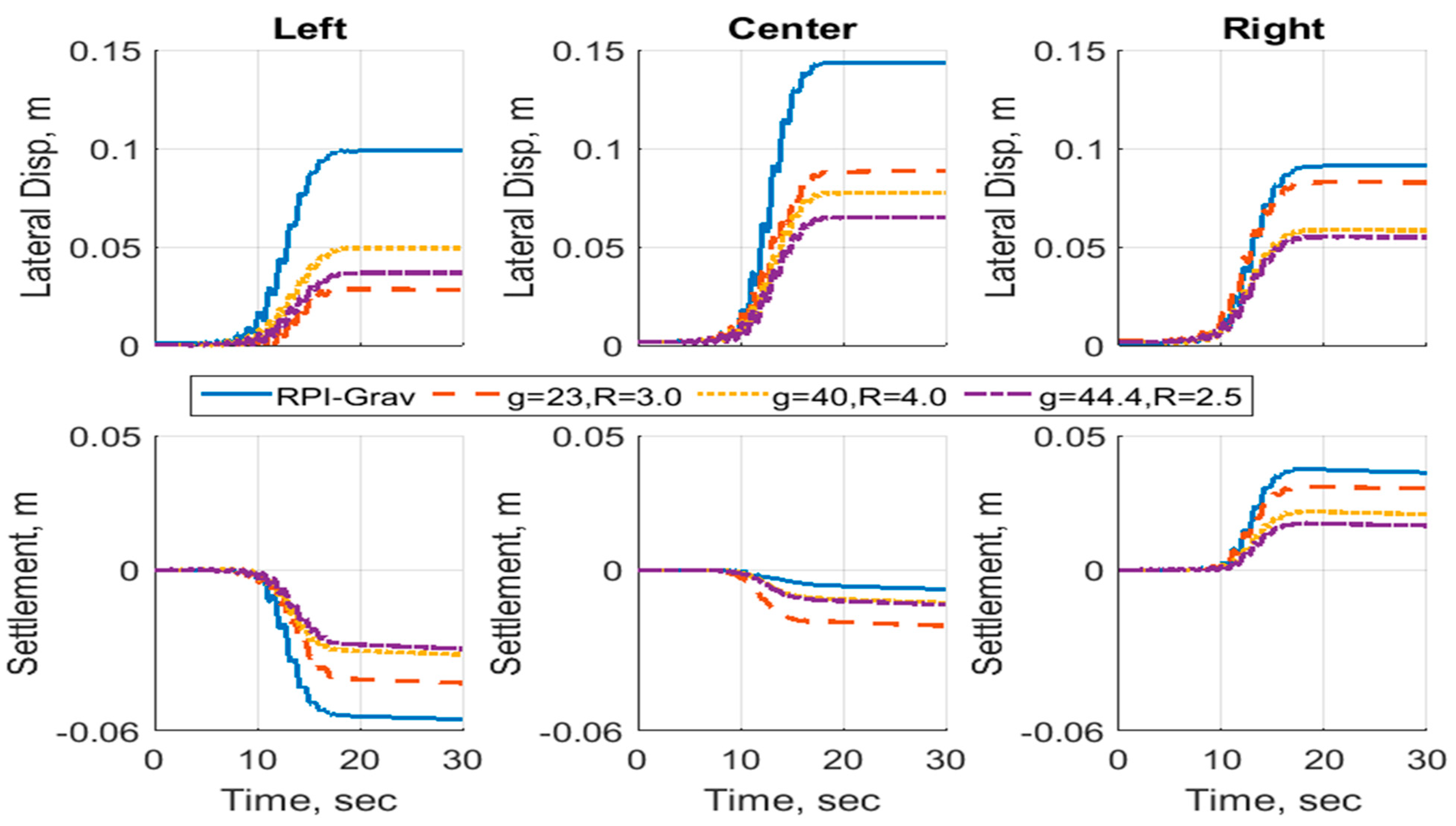
Different conclusions can be drawn from the displacements of the soil models, as shown in
Figure 19 and
Figure 20. While the curved surface geometry has proven to be useful to produce excess pore pressures that are similar to those from the gravitational case, the results for displacements vary with different model scales. This means that while the curved surface geometry may be used for modeling the pore pressures, it does not provide comparable displacements. Therefore, careful consideration of this fact should be taken when numerically modeling curved-surface centrifuge experiments. To simulate the experiment’s displacements more accurately, the simulation should be performed for the model scale and not the prototype.
7. Conclusions
The radial nature of the centrifugal acceleration field alters the stress distribution within centrifuge models, leading to a response that differs from that of the prototype under a uniform gravitational field. Numerical results indicate that this centrifugal acceleration promotes a more dilative soil response due to the shear stress ratio approaching the critical state, thereby generating lower excess porewater pressures. Incorporating a curved surface geometry into the model improves the simulation of pore pressure generation compared to flat-surface configurations. While displacement patterns between the gravitational and curved-surface cases show improved agreement, discrepancies remain. Additionally, model scale plays a significant role, as both the g-level and the centrifuge’s radius of rotation influence the effective acceleration field.
In summary, the centrifugal acceleration field can significantly affect soil behavior during liquefaction, making it essential to incorporate surface curvature in physical and numerical models to better replicate pore pressure development. However, the use of curved surfaces alone does not fully reproduce prototype-scale displacements. Therefore, careful consideration of acceleration field characteristics—particularly at high g-levels or with smaller centrifuge radii—is crucial. To accurately capture the dynamic soil response, finite element simulations of centrifuge experiments must account for both the surface curvature and the radial acceleration field.


