Review

Mathematical Modeling of the Rail Track Superstructure–Subgrade System

by
Dmytro Kurhan
1,
Szabolcs Fischer
2,3,* and
Vladyslav Khmelevskyi
1
1
Department of Transport Infrastructure, Ukrainian State University of Science and Technologies, UA-49010 Dnipro, Ukraine
2
Central Campus Győr, Széchenyi István University, H-9026 Győr, Hungary
3
Vehicle Industry Research Center, Széchenyi István University, H-9026 Győr, Hungary
*
Author to whom correspondence should be addressed.
Geotechnics 2025, 5(1), 20; https://doi.org/10.3390/geotechnics5010020
Submission received: 15 February 2025 / Revised: 13 March 2025 / Accepted: 14 March 2025 / Published: 16 March 2025

Abstract

:
The “rail track superstructure–subgrade” system is a sophisticated engineering structure critical in ensuring safe and efficient train operations. Its analysis and design rely on mathematical modeling to capture the interactions between system components and the effects of both static and dynamic loads. This paper offers a detailed review of contemporary modeling approaches, including discrete, continuous, and hybrid models. The research’s key contribution is a thorough comparison of five primary methodologies: (i) quasi-static analytical calculations, (ii) multibody dynamics (MBD) models, (iii and iv) static and dynamic finite element method (FEM) models, and (v) wave propagation-based models. Future research directions could focus on developing hybrid models that integrate MBD and FEM to enhance moving load predictions, leveraging machine learning for parameter calibration using experimental data, investigating the nonlinear and rheological behavior of ballast and subgrade in long-term deformation, and applying wave propagation techniques to model vibration transmission and evaluate its impact on infrastructure.

1. Introduction

Calculating the stress–strain state of a railway track is a critical task in railway engineering, as its accuracy directly impacts the safety, durability, and efficiency of railway infrastructure. The interaction between the track superstructure (rails, sleepers, and ballast) and the subgrade is a complex, multi-factor process influenced by both static and dynamic loads from rolling stock.
The rapid advancement of mathematical modeling, particularly for railway track-related challenges, has led to the significant diversification of model types—both in terms of representing physical processes and in the application of mathematical methods for practical solutions. A review of the scientific literature reveals that nearly every new study involves substantial modifications or adaptations to the existing modeling methods, often resulting in the creation of novel mathematical models with fundamental differences. Typically, these studies begin by justifying the selection, creation, or adaptation of a mathematical model tailored to the specific problem at hand.
Consequently, while it is theoretically possible to develop a comprehensive classification method of railway track mathematical models encompassing all types, approaches, and problems, such an endeavor would exceed the scope of a single publication. Recent review papers have adopted a more focused approach. For example, ref. [1] provides an in-depth review of Discrete Element Modeling for analyzing ballast stress states; ref. [2] examines mathematical models for studying the contact zone and mutual wear of the wheel and rail; ref. [3,4] offer an overview and classification of models for simulating the gradual degradation of railway tracks; ref. [5,6] provide a general review of modeling contact forces and stresses in non-spherical particles (a key application for studying ballast particle interactions); and ref. [7] reviews mathematical models for optimizing track stiffness in transition zones between standard track and high-stiffness structures like bridges.
This study focuses on modern approaches to the mathematical modeling of the “rail track superstructure–subgrade” system, specifically reviewing the most common types of mathematical models for such problems, methods for introducing external loads, and techniques for determining stress states in granular media within these models. To address this problem, five main classes of models have been considered:
  • Quasi-static analytical calculations, which provide compact analytical expressions for evaluating stresses and deflections;
  • Multi-body dynamics models based on the Lagrange–D’Alembert equations, describing the interaction between rolling stock and infrastructure;
  • The finite element method (FEM) in a static form, used for analyzing the stress–strain state of structures under given static loads;
  • FEM in a dynamic form, which accounts for inertial effects, damping, and the cyclic nature of loads;
  • Wave propagation-based models (wave theory), applied to the analysis of vibration processes, wave propagation in ballast and subgrade, and resonance effects.
Each of these approaches has distinct advantages and limitations, which determine their applicability depending on the specific problem at hand. This paper offers a systematic review of modern mathematical models for the “rail track superstructure–subgrade” system, evaluates their capabilities in modeling dynamic loads and the behavior of granular materials, and highlights future directions for improving the accuracy of railway infrastructure condition forecasting.
To address the problem, the second section provides a detailed analysis of the fundamental principles underlying each of the five identified classes of models, including their mathematical frameworks. The third section explores the methods for implementing external loads into these models. Finally, the fourth section discusses the representation of granular material behavior (ballast–subgrade) within the models and presents a comparative analysis based on this factor.

2. Main Classes of Mathematical Models and Their Methods

2.1. Quasi-Static Design Method

The foundational model for analytically calculating the stress state of a railway track involves representing the rail as an infinitely long beam supported by an elastic foundation. This beam deflects under the influence of a single vertical force, as illustrated in Figure 1.
The fundamental equation for this type of model is the rail deflection equation (Winkler’s method), which describes the geometric profile of rail deflection along its length z = f ( x ) in an isotropic elastic medium, with stiffness U under equilibrium conditions between the applied external load P and the elastic resistance of the medium q = f ( x ) . Depending on the problem being solved and the possibility of simplifying the calculations by neglecting certain parameters, some variations in the formulation of this equation are possible. These computational schemes are described in numerous sources. An example of an extended formulation of the rail deflection equation is Equation (1):
m d 2 z d t 2 + E I d 4 z d z 4 + d d z H d z d x + U y + I 0 d 4 z d x 2 d t 2 = P x , t ,
where m is the the equivalent mass of the rail; E I is the the bending stiffness of the rail; H is the longitudinal force; U is the modulus of elasticity of the rail foundation; I 0 is the moment of inertia per unit length of the rail relative to the central axis perpendicular to the vibration plane; and P x , t is the vertical moving load.
The direct inclusion of the external load P x , t in the differential rail deflection, Equation (1), prevents an analytical solution. Typically, the rotational inertia (moment of inertia per unit rail length relative to the central axis perpendicular to the vibration plane, I 0 ) is neglected, as the rail’s length significantly exceeds its cross-sectional dimensions. The longitudinal force H varies slowly, so its differential term is also neglected. The determination of H is necessary for analyzing the stability of continuous welded rails against buckling; however, solving such problems requires different computational schemes that consider the equilibrium of the rail-sleeper grid.
In a more practical form, the deflection due to a moving load on a curved beam lying on a viscoelastic bed frame can be determined from Equation (2). In most sources, this approach is referred to as the Zimmermann–Eisenmann quasi-static design method [8]:
E s I s 4 w x , t x 4 + m 2 w x , t t 2 + D w x , t t + U d y n · 10 6 · w x , t = 0 ,
where Es is the modulus of elasticity of the rail material, Is is the moment of inertia of the rail on the horizontal axis, EsIs is the bending stiffness of the rail, m is the specific mass of the track structure, D is the damping specific to the track structure, Udyn is the dynamic rail support stiffness specific to the track structure, and w(x,t) is the rail deflection.
Some parameters of these equations require a more detailed explanation. The equivalent mass of the rail ( m ) refers to the portion of the rail mass actively involved in the interaction process at a given moment in time and at a specific rail deflection. Naturally, this mass continuously changes, but expressing it as m = f z , t , or at least m = f z , makes an analytical solution of Equation (2) impossible. In most problems, the rail mass is neglected. However, in cases where considering the rail mass or other track components is essential, specialized approaches are used for its determination and incorporation into the calculations.
Modulus of elasticity of the rail foundation ( U ). The modulus of elasticity in this context refers to the uniformly distributed stiffness of the rail foundation. The value of this parameter significantly influences the calculation results, affecting both deflections and stresses. It is essential to distinguish between the modulus of elasticity at the point under the rail (assuming the rail rests on discrete supports—this is the value obtained when a rail is statically loaded and its deflection is measured); the modulus of elasticity along the rail’s length (assuming the rail is supported by a continuous elastic foundation); and the static vs. dynamic modulus of elasticity, as their values differ depending on the loading conditions. For the rail deflection equation in the form of Equation (2), the dynamic modulus of elasticity is required. It is important to consider that this parameter is not constant; it varies depending on the rail deflection (in a nonlinear manner, meaning its change over time must be considered during rail oscillations) and along the rail’s length: U = f t , z . However, incorporating such a dependency not only complicates calculations, but also raises the issue of correctly defining the modulus of elasticity in the initial data.
By applying a series of assumptions, Equation (2) can be significantly simplified into the form commonly used in most practical calculations:
E I d 4 z d x 4 + U z = 0
or in a more conventional form:
d 4 z d x 4 + 4 k 4 z = 0
where k = U 4 E I 4 .
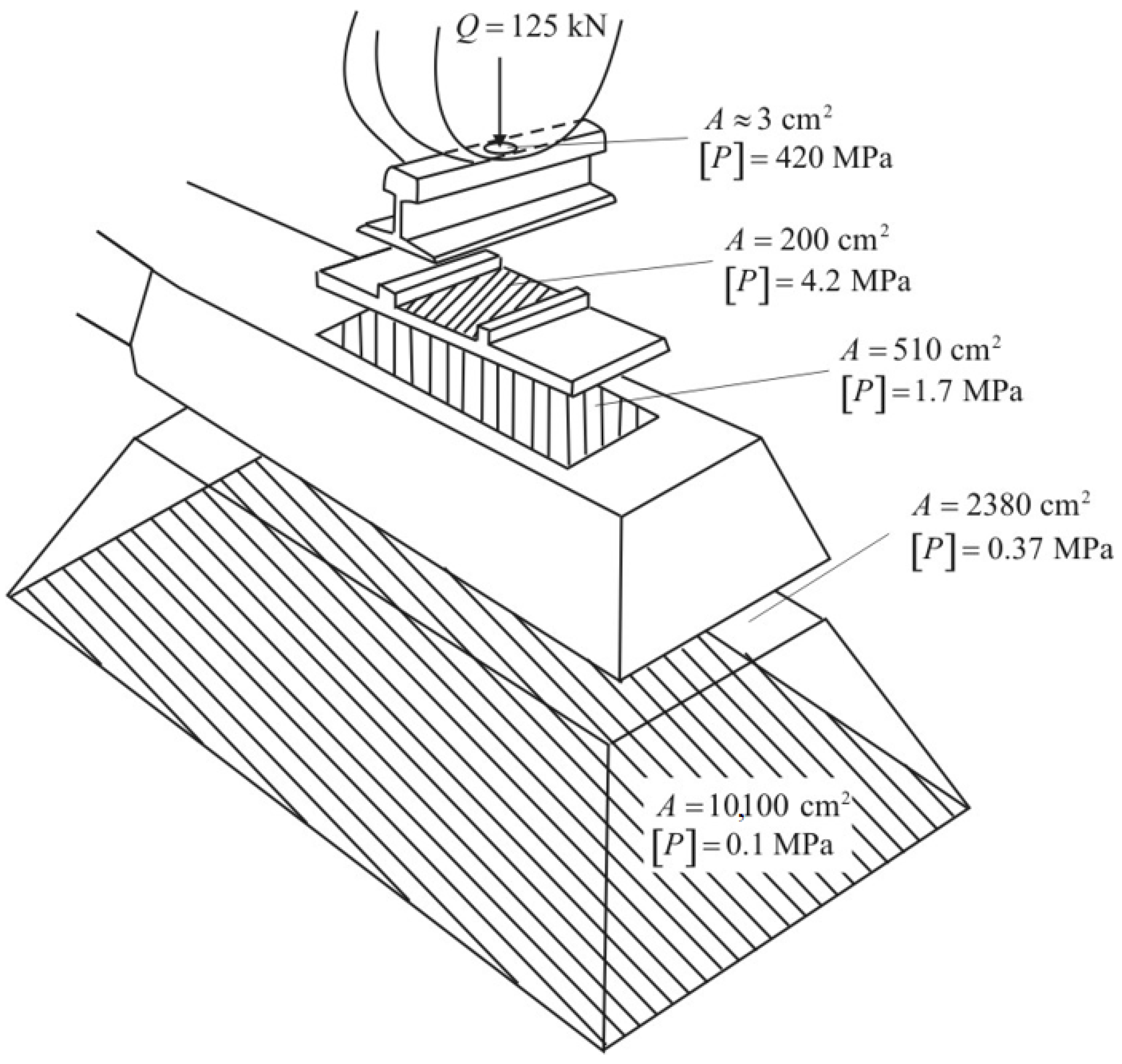
Solving Equation (4) enables the analytical calculation of bending stresses in the rail, rail deflection, and the force transmitted by the deflected rail to the rail foundation, all of which depend on the track structure and the applied external load. Stresses in other track components can be determined by analyzing the load transfer area. The overall computational scheme is illustrated in Figure 2.
For instance, in [10], a quasi-static model is employed to study the behavior of reinforced concrete sleepers, in [11] to analyze train movement characteristics on curved track sections, and in [12] to predict rail wear.
Quasi-static analytical models are widely utilized for preliminary railway track design analysis (express calculations), evaluating the stress–strain state of rails and the rail foundation under principal stresses, determining permissible loads for various types of track superstructures, analytically assessing track stiffness and its impact on rolling stock, and addressing other related problems. These models function both as independent mathematical tools and as integral components within more complex mathematical models.

2.2. Mathematical Models of Multibody Dynamics (MBD)

Multibody dynamics models are typically formulated using the Lagrange–D’Alembert equations. These models are employed for the dynamic analysis of railway track systems, especially when modeling rolling stock and track–vehicle interaction. This approach is grounded in the variational principle, enabling the incorporation of inertial forces, damping, and the elastic properties of the system. The second-order Lagrange equation in its classical form is expressed as Equation (5):
d d t L q j ˙ L q j = Q j *
where L = T V is the Lagrangian of the system, defined as the difference between the kinetic energy (T) and potential energy (V). q j represents the generalized coordinates describing the displacement (or rotation) of an object’s center of mass relative to one of the coordinate axes (e.g., rail displacement, sleeper movement, wheelset motion, or car body oscillations, etc.), and Q j * denotes the generalized forces, including friction forces, damping, and external perturbations.
By substituting the standard expressions for kinetic energy (as a function of mass and velocity squared) and potential energy (as a function of coordinate change and stiffness) and performing mathematical transformations, Equation (5) can be rewritten in the classical form for oscillations of the i-th object in the j-th generalized coordinate dimension:
m i q ¨ i i + c i q ˙ i i + k i q i j = Q i j * ,
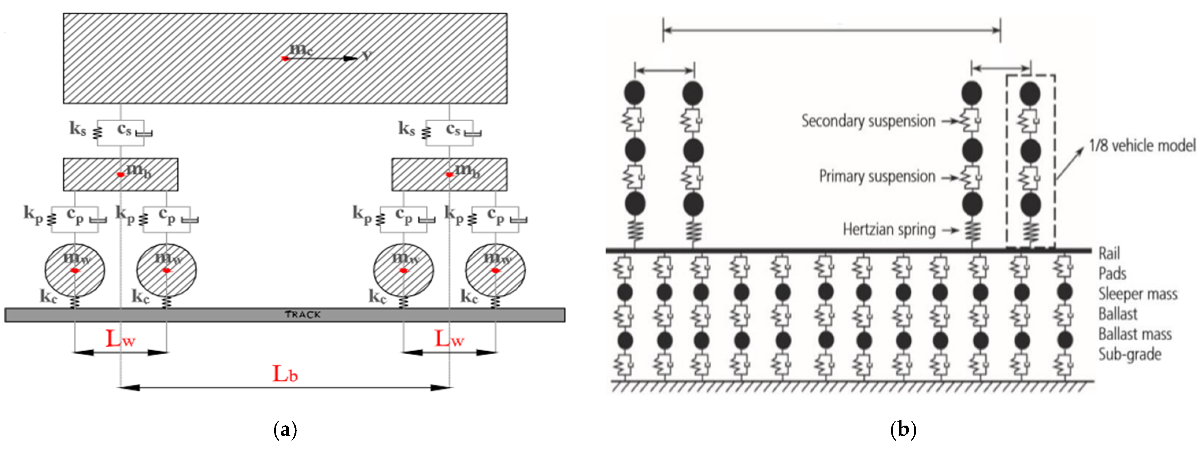
Thus, the system of Equation (6) describes the dynamic equilibrium of a system composed of mass-carrying objects (m), whose displacements are constrained by stiffness (k) and dissipative (c) connections (Figure 3).
Given the formulation principles of equations of the type (6) (i.e., Equation (6)), multi-body dynamics (MBD) models are widely used in railway vehicle dynamics. Locomotives and railcars can be decomposed into systems of discrete bodies (e.g., wheels or wheelsets, bogies, and car bodies) without significant loss of physical accuracy.
However, incorporating the railway track into such models presents considerable challenges. First, segmenting long-track elements (rails, ballast layer, or subgrade) into discrete mass objects (see Figure 3b) requires the introduction of the so-called equivalent mass, which accounts for the mass of a track section reduced to the point of interaction, considering changes in kinetic energy [15]. Second, the rail deflection, ballast elasticity, and subgrade deformation are not identical to the displacement of the object’s center of mass. Therefore, using MBD models for subgrade behavior analysis has certain limitations.
MBD models have been successfully applied in various railway studies: ref. [16,17] investigate track sections with transitional (variable) stiffness, ref. [18] examines the influence of freight car body bending deformations on track interaction, and ref. [19] explores the dynamic processes caused by longitudinal cargo displacement inside a wagon.
Thus, this class of mathematical models has been most extensively applied in vehicle–track interaction studies from the perspective of rolling stock dynamics: vibration analysis of wheelsets, suspension systems and other rolling stock components, assessment of track irregularities’ impact on train dynamics, and the optimization of wagon and locomotive design parameters to reduce dynamic loads.
To solve problems related to the railway track, infinitely long models can be applied in multi-body dynamics. This approach eliminates the boundary effects typical for traditional finite models and allows for a focus on the global behavior of the system in space and time.
In multi-body dynamics models using such approaches, the railway track is assumed to be either infinitely long, quasi-infinite, or a periodically repeating structure. As a result, its physical parameters remain unchanged along the direction of motion. The train-induced load is moving and time-dependent, enabling the analysis of dynamic processes without explicitly modeling finite track sections. Mathematical tools such as spectral methods, Fourier transforms, and modal approaches are used to examine the system’s response to different types of loads in the frequency domain. With this approach, the dynamic response of an infinite railway track is primarily described using the classical equations of beam motion on an elastic foundation, Equation (1).
For example, in [20], an infinite multi-body dynamics model was used to study the attenuation of rail bending vibrations, while in [21], it was applied to justify measures for reducing railway track vibrations.

2.3. Finite Element Method (FEM) in Static Analysis of Railway Track

The finite element method (FEM) is an effective numerical approach for analyzing the stress–strain state of railway track structures. It enables the consideration of complex geometry, material heterogeneity, and interactions between structural elements. In static analysis, the computation is based on equilibrium equations for all nodes of the finite element mesh. The fundamental matrix form of these equations is Equation (7); see below:
K · U = P
where K is the stiffness matrix of the system, dependent on the physical properties of railway track elements (layers); U is the vector set of nodal displacements; and P is the vector set of external loads.
The model incorporates the appropriate boundary conditions, such as rigid or elastic fixation of the modeled domain’s boundaries (e.g., subgrade base and slopes), minimum and maximum mesh sizes, and, in some cases, elemental geometric shapes.
FEM allows for determining the stresses, deformations, and displacements within railway track elements. High mesh refinement ensures accurate calculations of complex structures involving materials with nonlinear properties or localized material inclusions. This flexibility enables the modeling of not only standard railway track designs, but also customized configurations or those affected by operational changes over time.
On the other hand, high mesh refinement requires significant computational resources, making the modeling process a trade-off between simulation parameters and result accuracy.
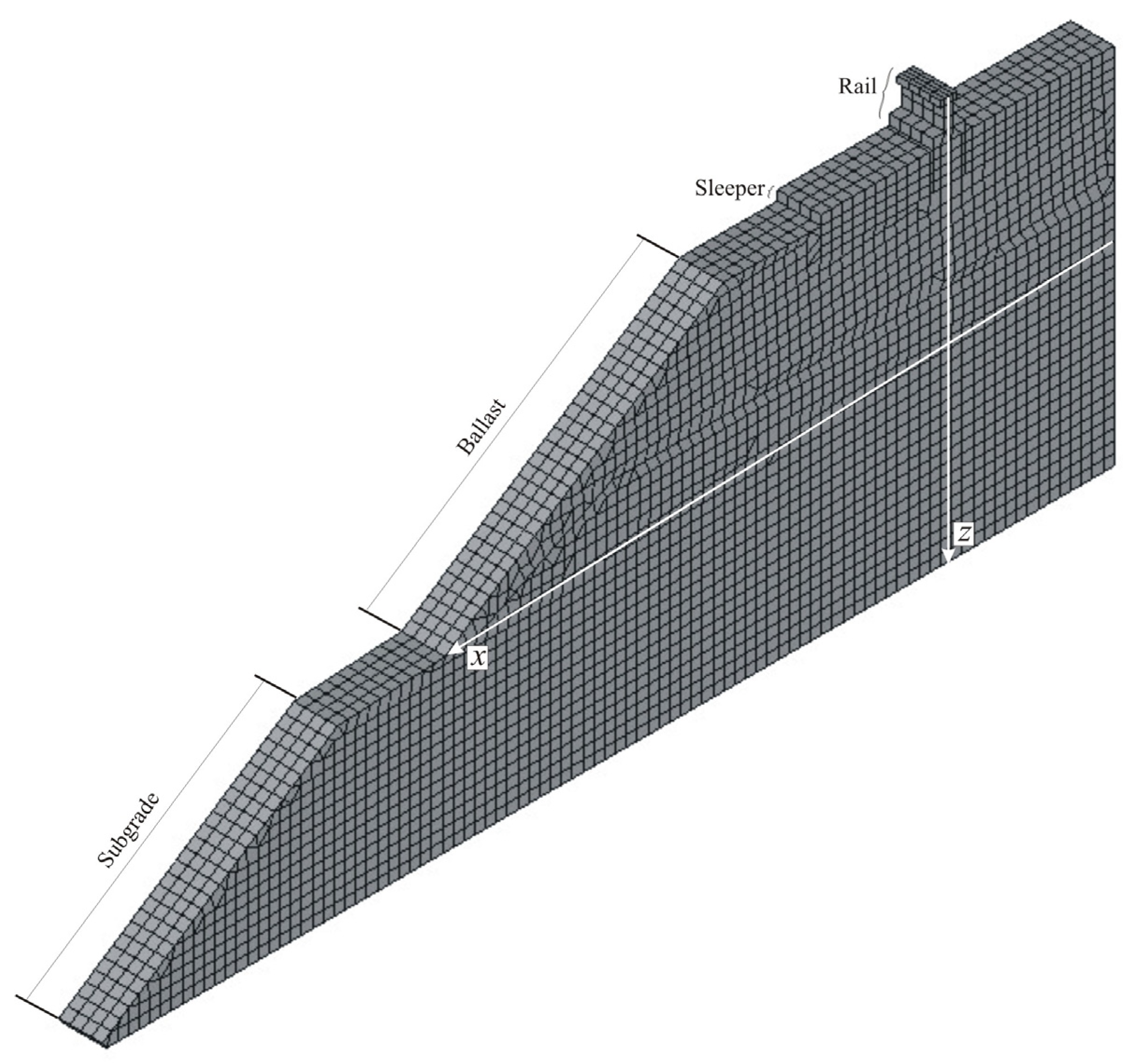
A spatial finite element model of the railway track is shown in Figure 4. The authors of the current study used this model to analyze the stress–strain state of the subgrade, applying different reinforcement methods. To optimize computational resources, the model included a 6.0 m high and 0.2 m long railway track segment, consisting of 0.05 × 0.05 × 0.05 m elements [22].
Currently, FEM is a key tool in railway infrastructure analysis, providing a detailed evaluation of the stress–strain state under external loads for most engineering applications. In studies that compare different modeling approaches, FEM is frequently preferred for modeling the railway substructure [14]. FEM applications in railway research include the following: effectiveness analysis of subgrade reinforcement methods [23,24,25,26,27]; justification for using geotextile materials and geogrids in track design [28,29,30,31,32]; residual deformation accumulation processes and mitigation [33]; modeling embankment reinforcement on weak soils [34]; stress–strain analysis of railway tracks under high axial loads [35]; the evaluation of noise and vibration reduction methods [36,37]; a detailed analysis of stress distribution within the rail [38,39]; and vehicle movement on tracks with variable stiffness [40,41].

2.4. Finite Element Method (FEM) in Dynamic Analysis of Railway Track

In dynamic FEM models, the loading is a function of time P ( t ) , accounting for the velocity and displacement of rolling stock (wheels), as well as, in some cases, track irregularities, resonance effects, and other dynamic phenomena. Equation (6) is extended to incorporate inertial and dissipative effects (see Equation (8)):
M · U ¨ + C · U ˙ + K · U = P ( t )
where M is the mass matrix of the system and C is the damping matrix, accounting for energy dissipation due to friction and viscoelastic effects, etc.
Equation (8) includes not only nodal displacement vectors U , but also velocity U ˙ and acceleration U ¨ vectors. Numerical methods such as the Newmark method, central difference method, spectral methods, and modal analysis are typically used to solve such equations.
These computations require significantly higher computational power and time compared to static analysis. Although dynamic FEM modeling provides more realistic railway track simulations, it also makes multi-scenario calculations considerably more complex. This explains why such models are primarily used for problems where dynamic effects cannot be neglected, due to the nature of the process.
The preference for dynamic over static FEM models is not always obvious. Several studies evaluate the necessity of transitioning to dynamic analysis. For example, ref. [42] compares static and dynamic FEM models for subgrade reinforcement, while ref. [43] examines static vs. dynamic approaches for analyzing wheel–rail irregularities.
Typically, dynamic FEM is applied to high-speed rail analysis, vibration propagation studies, and the related problems. It analyzes the stress–strain state of railway tracks under high-speed train movement [44,45,46]; describes the development of a high-frequency FEM model for evaluating rail vibration damping efficiency to reduce noise and vibrations [47]; presents a mathematical model of the “vehicle–track” dynamic system for studying wheel–rail interaction forces in metro systems [48]; evaluates the dynamic stiffness of railway tracks [49]; investigates the stress–strain behavior of the ballast layer [50,51]; examines an unconventional track structure incorporating an asphalt layer [52]; analyzes the impact of wheel defects on track dynamics [53]; and explores the stress state of railway tracks under moving loads [54].

2.5. Wave Propagation-Based Models in Railway Track Analysis

Stress–strain state models of railway tracks based on elastic wave propagation rely on the principles of dynamic elasticity theory (wave theory). Their implementation involves combining the geometric equations that define the shape of the space interacting at a given moment with the dynamic equilibrium equations governing its deformation.
To construct such a model, the railway track is considered a spatial system of objects characterized by their geometric dimensions and physical properties, which determine the wave propagation velocities and elastic and shear deformation parameters. The response to external forces is modeled as the generation and propagation of spatial spherical waves within the material. Wave propagation is influenced by object dimensions and considers changes in wave parameters at material boundaries. The fundamental wave equation for deformation in an elastic medium is as follows (see Equation (9)):
ρ 2 t 2 = λ + 2 μ 2
where ρ is the density of the medium; λ i μ are the Lamé parameters; is the deformation vector; and is the Laplace operator.
The practical application of such models typically involves solving two key problems: (i) determining the geometry of the railway track space involved in the interaction at a given moment under the applied load, including the wave front shape and material properties of different interacting elements. This is generally described using Equation (10). (ii) Determining the dynamic deformation of the material as the elastic wave propagates through it, described by the system of Equation (11).
A computational scheme illustrating the functioning of this mathematical model is shown in Figure 5.
υ t , α = C t C l t C t 2 cos 2 α + C l 2 sin 2 α ; C l = E 1 μ ρ 1 + μ 1 2 μ ; C t = E 2 ρ 1 + μ ,
d m i d 2 u i d t 2 = σ i 1 S i 1 σ i S i
where E is the Young’s modulus; d m i is the mass of an elementary computational segment; S i i S i 1 are the areas of the previous and next segment walls; σ i i σ i 1 are the stresses acting on the previous and next segment walls; and u i is the vibration amplitude (dynamic deformation) within the segment (see Figure 5).
The primary application of this class of mathematical models for railway track analysis lies in problems where dynamic deformation must be explicitly considered. These include assessing resonance phenomena during train movement, studying vibration propagation in the subgrade, and evaluating its impact on the surrounding infrastructure. One of the key research directions involves calculations for high-speed rail systems, particularly under conditions where train speed approaches the stress wave propagation velocity in soil layers.
An advantage of these models is their ability to restrict calculations to the portion of the computational domain directly involved in the interaction, allowing for the optimization of computational resources compared to the finite element method (FEM). As a result, a growing trend is observed in the sequential application of wave propagation-based models to define the computational domain boundaries, followed by FEM-based analysis to determine the stresses and deformations under applied loads.
For example, wave propagation-based models are used to compare rail deflection profiles at different train speeds [56]; researchers are employed to determine the equivalent masses of railway track components for subsequent use in multi-body dynamics (MBD) models [15]; authors are employed to evaluate the deformation characteristics of railway ballast [9]; scholars assess the feasibility of using retaining walls for embankments [57]; researchers enable stochastic analysis of dynamic stress amplification factors in slab track structures [58]; and authors investigate the generation of railway-induced vibration and noise and methods to mitigate their effects [59].
These models have also been used in many other studies across various applications. A combined approach integrating wave propagation-based models with FEM has been employed; this hybrid method is used to predict the impact of rolling stock characteristics on track settlement [60]. It is applied to model the settlement of ballasted and ballastless track structures at speeds exceeding 200 km/h [61].

3. Implementation of External Loading in the Models

In modeling the interactions between rolling stock, railway track, and the subgrade, the correct approach to applying external loading is critically important. Depending on the process under study and the specific research objective, the applied load can be static (or quasi-static), dynamic, or introduced through frequency-based or other harmonic methods.
  • Static loading is used when the force changes slowly over time, allowing the inertial effects to be neglected. This approach is often applied to assess the load-bearing capacity of the subgrade and ballast layer under rolling stock loads.
  • Quasi-static methods are employed when train speed or other factors lead to variations in the actual wheel–rail load compared to the static case. In this case, the force is represented as a combination of static and dynamic components. The dynamic component is typically introduced using the root mean square (RMS) deviation of real load fluctuations, with a specified probability threshold for the upper limit.
In most cases, it is assumed that the wheel–rail contact force follows a Gaussian distribution. The RMS deviation can be determined as a function of train speed, for instance, using Equation (12) [62,63]. Alternatively, more complex methods may be employed to account for car body oscillations on suspension springs, wheel irregularities, deviations in track maintenance quality, and other influencing factors [64,65,66].
P d y n = P s t a t + t s ¯ P s t a t ; s ¯ = n φ ; φ = 1 + V 60 140
where P d y n is the quasi-static wheel load on the rail (kN); Q s t a t is the static wheel load on the rail (kN); t is the statistical distribution coefficient, for t = 3, the calculation accuracy is 99.7%; n is a coefficient accounting for track condition, typically within the range of 0.1–0.3; φ is the speed factor; and V is the train speed (km/h).
In cases where static or quasi-static loading does not allow for the creation of an adequate mathematical model, dynamic loading is used. Dynamic loading requires not only the application of a variable force magnitude, but also the use of appropriate mathematical approaches that account for both the applied load and the inertia of its variation.
Dynamic loading, where both the force magnitude and its position change explicitly, significantly complicates the required mathematical framework, making such approaches less common. A substantial simplification can be achieved by applying frequency-based and other harmonic methods [67].
Some models use a conditional force-displacement approach. For example, in multibody dynamics models, a local coordinate system is typically used to describe the oscillations of a railcar or locomotive “in place”. In such cases, train movement at a given velocity is represented by an adjusted time-stepping scheme in the numerical calculations.

4. Implementation of Granular Material Behavior (Ballast and Subgrade) in the Models

The modeling of granular materials, such as ballast and subgrade, is a crucial aspect of analyzing the stress–strain state of the railway track. These materials exhibit complex mechanical behavior, distinct from elastic and plastic media, as they are characterized by a discrete structure, internal friction, and the potential for irreversible deformations.
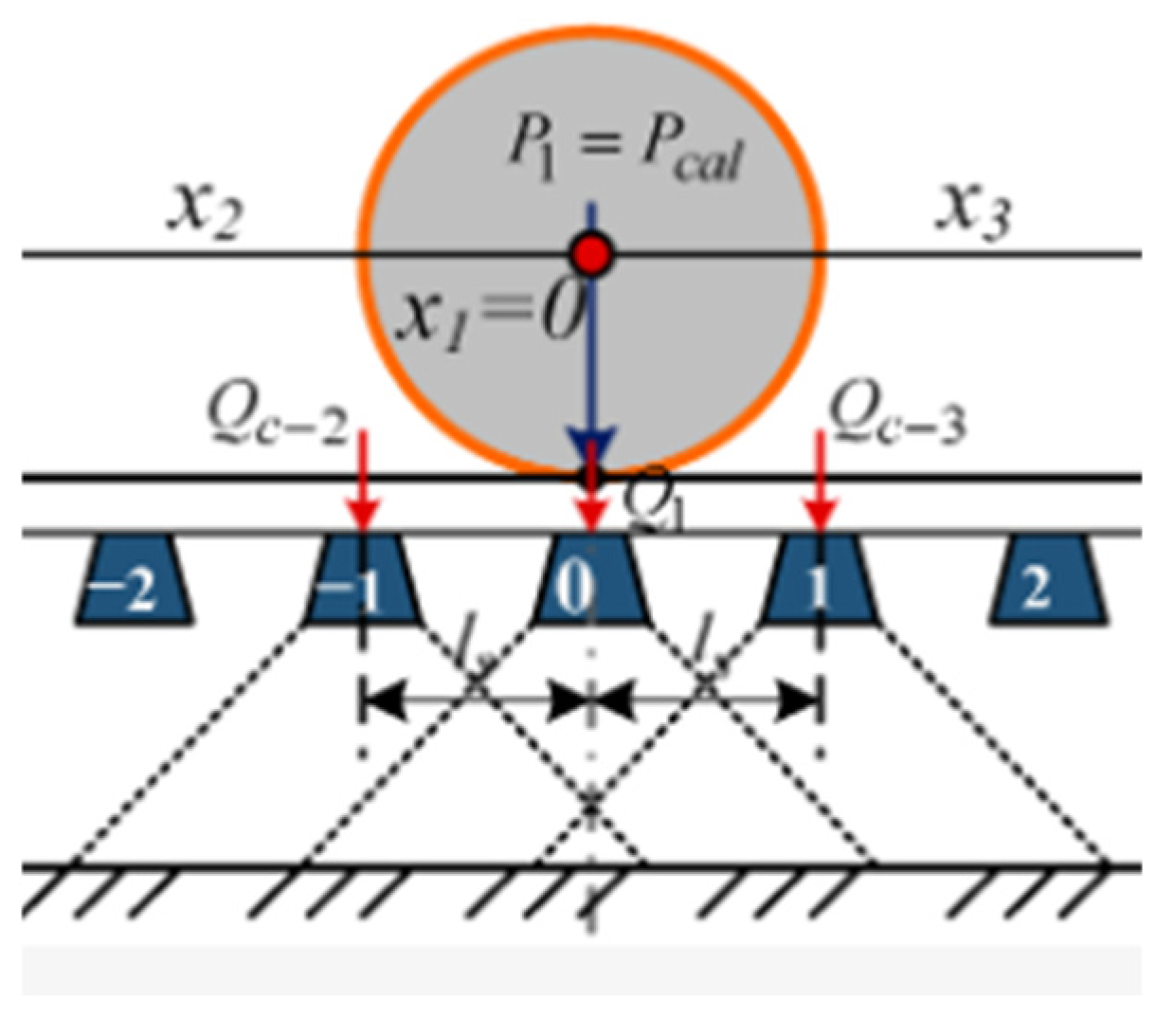
To adequately represent these characteristics, various modeling approaches are employed. In analytical calculations under static (quasi-static) loading, stresses in the subgrade are determined using classical elasticity theory. Typically, it is assumed that the load on an elastic half-space, consisting of a ballast layer and soil, is transmitted as rectangular pressure from the sleeper base. The subsequent stress distribution in the half-space is computed using well-known Boussinesq equations. In some cases, additional factors may be considered, such as the non-uniform pressure distribution beneath the sleeper base or the influence of adjacent sleepers [64,68], as shown in Figure 6.
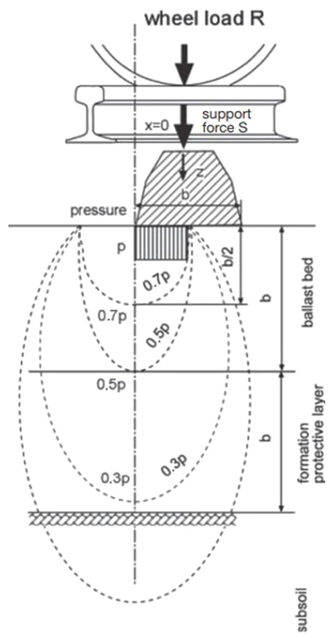
For rapid stress analysis, a simplified 2:1 method is often used. This method assumes that the load spreads at an angle of approximately 45° into the deeper layers, resulting in a gradual decrease in pressure, as illustrated in Figure 7. A comparison of different analytical stress calculation methods for soil is provided in [69].
In multi-body dynamics (MBD) models based on Lagrange’s second-type equations, the method for determining stresses in ballast and soil depends on the level of detail in the railway track model. If ballast and subgrade are considered a set of discrete bodies with defined equivalent masses, stresses are calculated at contact points between elements through generalized displacements. However, in most cases, the subgrade is treated as a continuous medium. In this case, MBD models serve as a source of input loading, and stress calculations are performed using analytical elasticity theory methods or the finite element method (FEM).
In FEM-based analysis, stress determination in the railway subgrade relies on solving continuum mechanics equations. For most problems, a linear elastic approach is sufficient. This approach follows classical elasticity theory, assuming that ballast and subgrade behave as a homogeneous continuous medium, with stress and strain relationships governed by Hooke’s law. For more complex problems, nonlinear approaches may be applied to account for stress-dependent material properties and plastic deformations.
In such cases, two key modeling aspects must be considered: (i) the level of discretization (modern FEM allows for adaptive meshing, enabling a finer resolution in critical areas) and (ii) the size of the modeling domain (smaller computational domains reduce hardware requirements while allowing for greater detail).
However, modeling small computational zones requires careful load definition at the domain boundaries and the proper assignment of boundary conditions. In most cases, even when analyzing stress and deformation in the subgrade alone, it is advisable to include the entire cross-section of the railway track in the model. This ensures that loads are applied to the rail and subsequently distributed through the contact areas between different track components. Some problems require a sufficiently large modeling domain to accurately capture the physical behavior under study. For example, investigating rail deflection length necessitates a mathematical model extending several meters.
By their nature, elastic wave propagation models are more suitable for semi-infinite domains (such as the ballast layer and subgrade) than for beam structures or local computational zones. In these models, stresses in the half-space are determined by solving dynamic elasticity problems. The potential difference caused by wave passage is balanced by particle oscillations, resulting in elastic deformation. This approach allows for consideration of not only the dynamic nature of loading, but also the delay and inertia effects of elastic deformations.
A comparison of the advantages and limitations of different mathematical models for stress–strain analysis of ballast and subgrade is presented in Table 1.

5. Discussion

The mathematical modeling of the rail track superstructure–subgrade system is a complex task that requires the consideration of numerous mechanical, dynamic, and rheological factors. The analysis of existing approaches shows that each method has its advantages and limitations, which affect the accuracy and applicability of the obtained results.
One of the key challenges is accounting for the real properties of granular materials, particularly ballast. Analytical and simplified FEM models typically treat the ballast layer as a homogeneous continuous medium, which significantly simplifies calculations, but does not capture the complex discrete structure of the material. On the other hand, multi-body dynamics models allow for a more detailed representation of the interactions between individual particles; however, they have limitations in scalability and require significant computational resources.
Another important issue is the choice of loading approach. Quasi-static models are well suited for assessing the load-bearing capacity of the subgrade, while dynamic methods are more appropriate for analyzing vibrations and wave propagation in the ground. In particular, wave theory enables the modeling of elastic wave propagation within the subgrade, which is critical for high-speed rail research. However, this model does not adequately account for the accumulation of plastic deformations.
The selection of the modeling scale also presents a challenge. Local models provide detailed analysis of specific structural elements, but require precise boundary conditions. Global models, which include large sections of railway infrastructure, allow for the evaluation of processes over extensive spatial and temporal scales, but are computationally demanding.
Future research in this field may focus on developing hybrid methods that combine different mathematical approaches. For example, integrating multi-body models with FEM calculations could allow for more accurate consideration of ballast and subgrade deformation under moving loads. Additionally, applying machine learning techniques for model parameter calibration based on experimental data is a promising direction.
Thus, improving mathematical models of rail track superstructure–subgrade interaction remains a crucial task for enhancing the reliability and durability of railway infrastructure, especially under increasing loads and higher train speeds.

6. Conclusions

The main contribution of this study is a systematic review of modern mathematical models for analyzing the stress–strain state of the “rail track superstructure–subgrade” system. The novelty of the research lies in the comprehensive comparison of five main approaches: quasi-static analytical calculations, multibody dynamics (MBD) models, the finite element method (FEM) in both static and dynamic forms, and wave propagation-based models. The review results show that the choice of modeling methodology largely depends on the research objectives, the required level of detail, and the necessity to account for dynamic effects.
Quasi-static analytical models are widely used to assess the load-bearing capacity of the subgrade and ballast layer. However, they do not account for nonlinear and plastic material properties, which limits their applicability under variable loading conditions.
Multibody dynamics models allow for the description of the interactions between rolling stock and the track, including load transmission through the “wheel–rail–sleeper-ballast” system. However, their accuracy depends on the level of detail in representing granular materials.
The finite element method (FEM) in its static form provides accurate calculations of stresses and deformations in a continuous medium, while dynamic FEM models allow for the consideration of nonlinearity, damping, and plastic strain accumulation. However, they require significant computational resources.
Wave propagation models are effective for describing the transmission of dynamic loads in the subgrade. However, their application is limited by the need to account for long-term deformation accumulation and settlement processes.
Thus, selecting the optimal modeling approach for the rail track superstructure–subgrade system depends on the specifics of the investigated process. Future research may focus on: (i) developing hybrid models that combine MBD and FEM to improve the prediction of moving load effects; (ii) implementing machine learning techniques to calibrate model parameters based on experimental data; (iii) analyzing the nonlinear and rheological properties of ballast and subgrade in long-term deformation processes; or (iv) applying wave propagation methods to model vibration transmission and assess its impact on infrastructure.
Laboratory tests and modeling [70,71,72,73,74,75,76,77,78], as well as field tests [79,80,81,82,83,84,85,86,87,88,89], are also worth mentioning, as well as models of the rail track with an elastic n-layered computer software [68], and the application of artificial intelligence and machine learning [90,91,92,93].

Author Contributions

Conceptualization, D.K. and S.F.; methodology, D.K.; investigation, D.K., S.F and V.K.; resources, V.K.; writing—original draft preparation, V.K.; writing—review and editing, D.K. and S.F; visualization, D.K.; project administration, S.F. All authors have read and agreed to the published version of the manuscript.

Funding

This research received no external funding.

Data Availability Statement

The data are contained within the article.

Acknowledgments

The authors express gratitude to the employees of the Ukrainian State University of Science and Technologies and the members of the “SZE-RAIL” research team and the Vehicle Industry Research Center at Széchenyi István University. This research was conducted as part of the SIU Foundation’s project entitled ‘Sustainable railways—Investigation of the energy efficiency of electric rail vehicles and their infrastructure’.

Conflicts of Interest

The authors declare no conflicts of interest.

References

  1. Aela, P.; Powrie, W.; Harkness, J.; Jing, G. Discrete Element Modelling of Railway Ballast Problems: An Overview. Arch Comput. Methods Eng 2024. [Google Scholar] [CrossRef]
  2. Bosso, N.; Magelli, M.; Zampieri, N. Simulation of wheel and rail profile wear: A review of numerical models. Rail. Eng. Sci. 2022, 30, 403–436. [Google Scholar] [CrossRef]
  3. Ehrhart, U.; Knabl, D.; Marschnig, S. Track Deterioration Model—State of the Art and Research Potentials. Infrastructures 2024, 9, 86. [Google Scholar] [CrossRef]
  4. Rempelos, G.; Ognibene, G.; Le Pen, L.; Blainey, S.; Preston, j.; Powrie, W. Railway Track Deterioration Models: A Review of the State of the Art. Transp. Geotech. 2024, 49, 101377. [Google Scholar] [CrossRef]
  5. Feng, Y.T. Thirty years of developments in contact modelling of non-spherical particles in DEM: A selective review. Acta Mech. Sin. 2023, 39, 722343. [Google Scholar] [CrossRef]
  6. Kildashti, K.; Dong, K.; Yu, A. Contact force models for non-spherical particles with different surface properties: A review. Powder Technol. 2023, 418, 118323. [Google Scholar] [CrossRef]
  7. Indraratna, B.; Sajjad, M.B.; Ngo, T.; Correia, A.G.; Kelly, R. Improved performance of ballasted tracks at transition zones: A review of experimental and modelling approaches. Transp. Geotech. 2019, 21, 100260. [Google Scholar] [CrossRef]
  8. Major, Z.; Németh, A.; Jóvér, V.; Liegner, N.; Fischer, S. Dynamic Modeling Possibilities of Embedded Rail Structures. Acta Polytech. Hung. 2025, 22, 29–43. [Google Scholar] [CrossRef]
  9. Kurhan, D.; Kurhan, M.; Horváth, B.; Fischer, S. Determining the Deformation Characteristics of Railway Ballast by Mathematical Modeling of Elastic Wave Propagation. Appl. Mech. 2023, 4, 803–815. [Google Scholar] [CrossRef]
  10. Tran, L.-H.; Hoang, T.; Duhamel, D.; Foret, G.; Messad, S.; Loaec, A. A Fast Analytic Method to Calculate the Dynamic Response of Railways Sleepers. J. Vib. Acoust. 2019, 141, 11005. [Google Scholar] [CrossRef]
  11. Bettaieb, H. Analytical dynamic and quasi-static model of railway vehicle transit to curved track. Mécanique Ind. 2012, 13, 231–244. [Google Scholar] [CrossRef]
  12. Ciotlaus, M.; Kollo, G.; Fenesan, C.; Danciu, A.D.; Dragomir, M.L.; Marusceac, V. Rail Wear Evolution on Small-Radius Curves under Mixed Traffic Conditions, In-Field Investigations. Appl. Sci. 2024, 14, 29. [Google Scholar] [CrossRef]
  13. Gia, K.N.; Ruigómez, J.M.G.; Castillo, F.G. Influence of rail track properties on vehicle–track responses. Proc. Inst. Civ. Eng.-Transp. 2015, 168, 499–509. [Google Scholar] [CrossRef]
  14. de Melo, A.L.O.; Kaewunruen, S.; Papaelias, M. Parameters and Boundary Conditions in Modelling the Track Deterioration in a Railway System. IOP Conf. Ser. Mater. Sci. Eng. 2019, 603, 032084. [Google Scholar] [CrossRef]
  15. Kurhan, D.; Leibuk, Y. Research of the Reduced Mass of the Railway Track. Acta Tech. Jaurinensis 2020, 13, 341. [Google Scholar] [CrossRef]
  16. Jain, A.; Metrikine, A.V.; Steenbergen, M.J.M.M.; van Dalen, K.N. Design of railway transition zones: A novel energy-based criterion. Transp. Geotech. 2024, 46, 101223. [Google Scholar] [CrossRef]
  17. Jain, A.; Metrikine, A.V.; Steenbergen, M.J.M.M.; van Dalen, K.N. Railway Transition Zones: Energy Evaluation of a Novel Transition Structure for Critical Loading Conditions. Vib. Eng. Technol. 2025, 13, 15. [Google Scholar] [CrossRef]
  18. Muradian, L.; Shvets, A.; Shvets, A. Influence of wagon body flexural deformation on the indicators of interaction with the railroad track. Arch. Appl. Mech. 2024, 94, 2201–2216. [Google Scholar] [CrossRef]
  19. Muradian, L.; Shvets, A.; Shvets, A. Some dynamic processes at longitudinally-transverse shift of the cargo. Sci. J. Silesian Univ. Technol. Ser. Transp. 2023, 120, 187–204. [Google Scholar] [CrossRef]
  20. Fologea, D.; Mazilu, T.; Gheți, M.-A.; Apostol, I.-I. Parametric Study on the Effect of Rail Dampers on Track Decay Rate. Appl. Sci. 2024, 14, 9541. [Google Scholar] [CrossRef]
  21. Mazilu, T.; Dumitriu, M.; Răcănel, I.-R. Parametric Study of the Influence of Nonlinear Elastic Characteristics of Rail Pads on Wheel–Rail Vibrations. Materials 2023, 16, 1531. [Google Scholar] [CrossRef]
  22. Tiutkin, O.; Kurhan, M.; Kurhan, M.; Miroshnyk, V. Numerical Analysis of Stabilization Schemes for the Deformed State of Railway Embankment Using Piles. Acta Polytech. Hung. 2025, 22, 213–226. [Google Scholar] [CrossRef]
  23. Alkhdour, A.; Tiutkin, O.; Fischer, S.; Kurhan, D. An Analytical Method for Determining the Stress–Strain State of a Subgrade with Combined Reinforcement. Infrastructures 2024, 9, 240. [Google Scholar] [CrossRef]
  24. Andrieiev, V.; Tiutkin, O.; Hubar, O.; Mukhina, N. Results of the Analysis of Reinforcing Structures Performance When Strengthening Subgrade Slopes. Transp. Means 2024, 2024, 678–684. [Google Scholar] [CrossRef]
  25. Guo, Q.; Li, B.; Ye, Z.; Xu, J. Finite Element Analysis on the Behavior of Solidified Soil Embankments on Piled Foundations under Dynamic Traffic Loads. Appl. Sci. 2024, 14, 4464. [Google Scholar] [CrossRef]
  26. Alsirawan, R.; Koch, E.; Alnmr, A. Proposed Method for the Design of Geosynthetic-Reinforced Pile-Supported (GRPS) Embankments. Sustainability 2023, 15, 6196. [Google Scholar] [CrossRef]
  27. Petrenko, V.; Bannikov, D.; Kharchenko, V.; Tkach, T. Regularities of the deformed state of the geotechnical system “soil base—Micropile”. IOP Conf. Ser. Earth Environ. Sci. 2022, 970, 12028. [Google Scholar] [CrossRef]
  28. Alsirawan, R.; Koch, E. Dynamic analysis of geosynthetic-reinforced pile-supported embankment for a high-speed rail. Acta Polytech. Hung. 2023, 21, 31–50. [Google Scholar] [CrossRef]
  29. Eller, B.; Fischer, S. Application of concrete canvas for enhancing railway substructure performance under static and dynamic loads. Facta Univ. Ser. Mech. Eng. 2025, 23, 13326. [Google Scholar] [CrossRef]
  30. Farooq, M.A.; Meena, N.K.; Punetha, P.; Nimbalkar, S.; Lam, N. Experimental and computational analyses of sustainable approaches in railways. Infrastructures 2024, 9, 53. [Google Scholar] [CrossRef]
  31. Desbrousses, R.L.E.; Meguid, M.A. Effect of Subgrade Compressibility on the Reinforcing Performance of Railroad Geogrids: Insights from Finite Element Analysis. The Canadian Geotechnical Society. 2022. Available online: https://www.researchgate.net/publication/364242857 (accessed on 14 February 2025).
  32. Ngo, T.; Hasan, M. Finite element modelling of geogrids reinforced ballasted tracks. Transp. Infrastruct. Geotech. 2024, 11, 2425–2447. [Google Scholar] [CrossRef]
  33. Alsirawan, R.; Koch, E. The finite element modeling of rigid inclusion-supported embankment. Pollack Period. 2022, 17, 86–91. [Google Scholar] [CrossRef]
  34. Jankowski, W.; Sołkowski, J. The modelling of railway subgrade strengthening foundation on weak soils. Open Eng. 2022, 12, 539–554. [Google Scholar] [CrossRef]
  35. Xu, F.; Yang, Q.; Liu, W.; Leng, W.; Nie, R.; Mei, H. Dynamic stress of subgrade bed layers subjected to train vehicles with large axle loads. Shock Vib. 2018, 2018, 2916096. [Google Scholar] [CrossRef]
  36. Auersch, L. Reduction of train-induced vibrations—Calculations of different railway lines and mitigation measures in the transmission path. Appl. Sci. 2023, 13, 6706. [Google Scholar] [CrossRef]
  37. Hou, B.; Wang, D.; Wang, B.; Chen, X.; Pombo, J. Vibration reduction in ballasted track using ballast mat: Numerical and experimental evaluation by wheelset drop test. Appl. Sci. 2022, 12, 1844. [Google Scholar] [CrossRef]
  38. Zulkifli, M.A.; Basaruddin, K.S.; Abdul Rahim, Y.; Afendi, M.; Gurubaran, P.; Ibrahim, I. Three-dimensional finite element analysis on railway rail. IOP Conf. Ser. Mater. Sci. Eng. 2018, 429, 012010. [Google Scholar] [CrossRef]
  39. Kukulski, J.; Jacyna, M.; Gołębiowski, P. Finite element method in assessing strength properties of a railway surface and its elements. Symmetry 2019, 11, 1014. [Google Scholar] [CrossRef]
  40. Punetha, P.; Maharjan, K.; Nimbalkar, S. Finite element modeling of the dynamic response of critical zones in a ballasted railway track. Front. Built Environ. 2021, 7, 660292. [Google Scholar] [CrossRef]
  41. Bouhlal, L.; Kassou, F.; Lamdouar, N.; Bouyahyaoui, A. Assembly procedure for elementary matrices of train-track-bridge railway system. arXiv 2024. [Google Scholar] [CrossRef]
  42. Deng, Y.; Zhao, H.; Li, L.; Yao, Z.; Li, L. Research on static and dynamic loading performance of geosynthetic reinforced and pile-supported embankment. Appl. Sci. 2023, 13, 13152. [Google Scholar] [CrossRef]
  43. Fesharakifard, R.; Dequidt, A.; Tison, T.; Coste, O. Dynamics of railway track subjected to distributed and local out-of-round wheels. Mech. Ind. 2013, 14, 347–359. [Google Scholar] [CrossRef]
  44. Chango, I.V.L.; Yan, M.; Ling, X.; Liang, T.; Assogba, O.C. Dynamic response analysis of geogrid reinforced embankment supported by CFG pile structure during a high-speed train operation. Lat. Am. J. Solids Struct. 2019, 16, 1–20. [Google Scholar] [CrossRef]
  45. Liu, X.; Xiao, J.; Cai, D.; Su, Q.; Yang, G.; Yuan, S.; Jiang, G. Recent advances in subgrade engineering for high-speed railway. Intell. Transp. Infrastruct. (Oxf. Univ. Press) 2023, 2, liad001. [Google Scholar] [CrossRef]
  46. Moreno, A.G.; López, A.A.; Carrasco García, M.G.; Turias, I.J.; Ruiz Aguilar, J.J. A novel application of computational contact tools on nonlinear finite element analysis to predict ground-borne vibrations generated by trains in ballasted tracks. Modelling 2024, 5, 1454–1468. [Google Scholar] [CrossRef]
  47. Kuchak, A.J.T.; Marinkovic, D.; Zehn, M. Parametric investigation of a rail damper design based on a lab-scaled model. J. Vib. Eng. Technol. 2021, 9, 51–60. [Google Scholar] [CrossRef]
  48. Darenskiy, A.N.; Malishevskaya, A.S. Using mathematical models of dynamic systems “crew-track” powers to study the interaction of rolling stock and tracks underground. Inf. Control Syst. Rail Transp. 2017, 1, 43–51. [Google Scholar] [CrossRef]
  49. Giner, I.G.; Alvarez, A.R.; Sánchez-Cambronero García-Moreno, S.; Camacho, J.L. Dynamic modelling of high-speed ballasted railway tracks: Analysis of the behaviour. Transp. Res. Procedia 2016, 18, 357–365. [Google Scholar] [CrossRef]
  50. Yahia Alabbasi, M.H. Geomechanical Modelling of Railroad Ballast: A Review. Arch. Comput. Methods Eng. 2019, 26, 327–365. [Google Scholar] [CrossRef]
  51. Hua, X.; Zatar, W.; Cheng, X.; Chen, G.S.; She, Y.; Xu, X.; Liao, Z. Modeling and Characterization of Complex Dynamical Properties of Railway Ballast. Appl. Sci. 2024, 14, 11224. [Google Scholar] [CrossRef]
  52. Hawksbee, S.; Grossoni, I.; Bezin, Y.; Lee, B.; Watson, G.; Milne, D.; Le Pen, L.; Abadi, T.; Jorge, P. Modelling the Improved Behaviour of a Switch Installed on Ballast-Asphalt Track. In Proceedings of the Fifth International Conference on Railway Technology: Research, Development and Maintenance, Montpellier, France, 22–25 August 2022; Volume 1. [Google Scholar] [CrossRef]
  53. Mosleh, A.; Aires Montenegro, P.; Alves Costa, P.; Calçada, R. Railway Vehicle Wheel Flat Detection with Multiple Records Using Spectral Kurtosis Analysis. Appl. Sci. 2021, 11, 4002. [Google Scholar] [CrossRef]
  54. Sayeed, M.A.; Shahin, M.A. Dynamic Response Analysis of Ballasted Railway Track–Ground System under Train Moving Loads Using 3D Finite Element Numerical Modelling. Transp. Infrastruct. Geotech. 2023, 10, 639–659. [Google Scholar] [CrossRef]
  55. Kurhan, D.; Kurhan, M. Modeling the Dynamic Response of Railway Track. IOP Conf. Ser. Mater. Sci. Eng. 2019, 708, 12013. [Google Scholar] [CrossRef]
  56. Kurhan, D.; Fischer, S. Modeling of the Dynamic Rail Deflection using Elastic Wave Propagation. J. Appl. Comput. Mech. 2022, 8, 379–387. [Google Scholar] [CrossRef]
  57. Feng, G.; Luo, Q.; Lyu, P.; Connolly, D.P.; Wang, T. An Analysis of Dynamics of Retaining Wall Supported Embankments: Towards More Sustainable Railway Designs. Sustainability 2023, 15, 7984. [Google Scholar] [CrossRef]
  58. Xie, H.; Luo, Q.; Wang, T.; Jiang, L.; Connolly, D.P. Stochastic analysis of dynamic stress amplification factors for slab track foundations. Int. J. Rail Transp. 2024, 12, 281–303. [Google Scholar] [CrossRef]
  59. Nielsen, J.C.O.; Pieringer, A.; Thompson, D.J.; Torstensson, P.T. Wheel–Rail Impact Loads, Noise and Vibration: A Review of Excitation Mechanisms, Prediction Methods and Mitigation Measures. Notes Numer. Fluid Mech. Multidiscip. Des. 2021, 150, 3–40. [Google Scholar] [CrossRef]
  60. Charoenwong, C.; Connolly, D.P.; Odolinski, K.; Alves Costa, P.; Galvín, P.; Smith, A. The Effect of Rolling Stock Characteristics on Differential Railway Track Settlement: An Engineering-Economic Model. Transp. Geotech. 2022, 37, 100845. [Google Scholar] [CrossRef]
  61. Charoenwong, C.; Connolly, D.P.; Colaço, A.; Alves Costa, P.; Woodward, P.K.; Romero, A.; Galvín, P. Railway slab vs ballasted track: A comparison of track geometry degradation. Constr. Build. Mater. 2023, 378, 131121. [Google Scholar] [CrossRef]
  62. Lichtberger, B. Thack Compendium; Eurailpress Tetzlaff–Hestra GmbH Co. KG.: Hamburg, Germany, 2005; Volume 634. [Google Scholar]
  63. Fisher, S.; Eller, B.; Kada, Z.; Németh, A. Railway Construction; Univ. –Győr Nonprofit Kft Győr: Győr, Hungary, 2015; Volume 334. [Google Scholar]
  64. Kovalchuk, V.; Sysyn, M.; Movahedi Rad, M.; Fischer, S. Investigation of the Bearing Capacity of Transport Constructions Made of Corrugated Metal Structures Reinforced with Transversal Stiffening Ribs. Infrastructures 2023, 8, 131. [Google Scholar] [CrossRef]
  65. Nabochenko, O.; Sysyn, M.; Gerber, U.; Krumnow, N. Analysis of Track Bending Stiffness and Loading Distribution Effect in Rail Support by Application of Bending Reinforcement Methods. Urban Rail Transit 2023, 9, 73–91. [Google Scholar] [CrossRef]
  66. Kurhan, D. Determination of Load for Quasi-static Calculations of Railway Track Stress-strain State. Acta Tech. Jaurinensis 2016, 9, 83–96. [Google Scholar] [CrossRef]
  67. Langcuyan, C.P.; Sadiq, S.; Park, T.W.; Won, M.S. Dynamic analysis of MSE wall subjected to surface vibration loading. Open Geosci. 2023, 15, 20220592. [Google Scholar] [CrossRef]
  68. Moretti, L.; Loprencipe, G.; Di Mascio, P. Competition in rail transport: Methodology to evaluate economic impact of new trains on track. In Proceedings of the Sustainability, Eco-Efficiency and Conservation in Transportation Infrastructure Asset Managementm, Pisa, Italy, 28 April 2014; pp. 669–675. [Google Scholar] [CrossRef]
  69. Petrenko, V.D.; Yampolskiy, D.O.; Sviatko, I.O. Comparative analysis of calculation models of railway subgrade. Sci. Transp. Prog. 2013, 4, 56–62. [Google Scholar] [CrossRef]
  70. Cao, X.; Li, Y.; Li, P.; Xu, J.; Zhang, X. Influence of Fastener Stiffness and Damping on Vibration Transfer Characteristics of Urban Railway Bridge Lines Using Vibration Power Flow Method. Appl. Sci. 2023, 13, 12543. [Google Scholar] [CrossRef]
  71. Choi, J.; Ahn, D.; Kim, S. Behavior Characteristics of a Booted Sleeper Track System According to Substructure Deformation. Appl. Sci. 2021, 11, 4507. [Google Scholar] [CrossRef]
  72. Cui, X.; Zhou, R.; Guo, G.; Du, B.; Liu, H. Effects of Differential Subgrade Settlement on Slab Track Deformation Based on a DEM-FDM Coupled Approach. Appl. Sci. 2021, 11, 1384. [Google Scholar] [CrossRef]
  73. Fattah, M.; Majeed, Q.; Joni, H. Effect of Degree of Saturation on Stresses and Pore Water Pressure in the Subgrade Layer Caused by Railway Track Loading. Railw. Sci. 2024, 3, 413–436. [Google Scholar] [CrossRef]
  74. Groll, W.; Sowiński, B.; Konowrocki, R. Study of Transitional Phenomena in Rail Vehicle Dynamics in Relation to the Reliability and Operational State of the Continuous Welded Rail Track in Terms of Rail Joints. Eksploat. Niezawodn.—Maint. Reliab. 2023, 25, 7. [Google Scholar] [CrossRef]
  75. Hasnayn, M.; McCarter, W.; Woodward, P.; Connolly, D. Railway Subgrade Performance after Repeated Flooding—Large-Scale Laboratory Testing. Transp. Geotech. 2020, 23, 100329. [Google Scholar] [CrossRef]
  76. Kuchak, A.T.J.; Marinkovic, D.; Zehn, M. Parametric Investigation of a Rail Damper Design Based on a Lab-Scaled Model. J. Vib. Eng. Technol. 2021, 9, 51–60, Correction to J. Vib. Eng. Technol. 2021, 9, 1805. [Google Scholar] [CrossRef]
  77. Kuchak, A.T.J.; Marinkovic, D.; Zehn, M. Finite Element Model Updating—Case Study of a Rail Damper. Struct. Eng. Mech. 2020, 73, 27–35. [Google Scholar] [CrossRef]
  78. Ézsiás, L.; Tompa, R.; Fischer, S. Investigation of the Possible Correlations between Specific Characteristics of Crushed Stone Aggregates. Spectr. Mech. Eng. Oper. Res. 2024, 1, 10–26. [Google Scholar] [CrossRef]
  79. Abbasi, A.; Zakeri, J.; Norouzi, E.; Mosayebi, S. Field Investigation on the Effect of the Tamping Machine and Dynamic Track Stabilizer on Changing the Rail Support Modulus. Proc. Inst. Mech. Eng. Part F J. Rail Rapid Transit 2024, 238, 1072–1083. [Google Scholar] [CrossRef]
  80. Choi, J.; Kim, S. Qualitative Prediction Model for Dynamic Behavior of Ballasted Tracks. Appl. Sci. 2020, 10, 6258. [Google Scholar] [CrossRef]
  81. Fattah, M.; Majeed, Q.; Joni, H. Stresses in Saturated and Unsaturated Subgrade Layer Induced by Railway Track Vibration. Infrastructures 2024, 9, 64. [Google Scholar] [CrossRef]
  82. Gao, X.; Wang, L.; Zhao, C.; Wang, P.; Yi, Q. Experimental and Simulation Study on Rail Admittance Characteristics in Turnout Area of Urban Rail Transit. J. Vib. Control 2023, 30, 3806–3820. [Google Scholar] [CrossRef]
  83. Jumabekov, B.; Ro’zmetov, Y.; Sultonov, S. Assessment of the Impact on the Railway Track of a Special Purpose Passenger Car Model 61-934. E3S Web Conf. 2021, 264, 02050. [Google Scholar] [CrossRef]
  84. Naeini, M.; Mohammadinia, A.; Arulrajah, A.; Horpibulsuk, S. Recycled Glass Blends with Recycled Concrete Aggregates in Sustainable Railway Geotechnics. Sustainability 2021, 13, 2463. [Google Scholar] [CrossRef]
  85. Park, S.; Kim, J.; Kim, J.; Lee, S.; Cho, K. Analysis of Dynamic Characteristics of Deformed Concrete Slab Track on Transition Zone in High-Speed Train Line According to Train Speeds. Appl. Sci. 2020, 10, 7174. [Google Scholar] [CrossRef]
  86. Sadeghi, J.; Rabiee, S.; Khajehdezfuly, A. Development of Train Ride Comfort Prediction Model for Railway Slab Track System. Lat. Am. J. Solids Struct. 2020, 17, e236. [Google Scholar] [CrossRef]
  87. Sysyn, M.; Nabochenko, O.; Kovalchuk, V. Experimental Investigation of the Dynamic Behavior of Railway Track with Sleeper Voids. Railw. Eng. Sci. 2020, 28, 290–304. [Google Scholar] [CrossRef]
  88. Xiao, Y.; Chang, Z.; Mao, J.; Zhou, S.; Wang, X.; Wang, W.; Long, Y. Evaluating the Effect of Rail Fastener Failure on Dynamic Responses of Train-Ballasted Track-Subgrade Coupling System for Smart Track Condition Assessment. Materials 2022, 15, 2675. [Google Scholar] [CrossRef] [PubMed]
  89. Fischer, S. Investigation of the Settlement Behavior of Ballasted Railway Tracks Due to Dynamic Loading. Spectr. Mech. Eng. Oper. Res. 2025, 2, 24–46. [Google Scholar] [CrossRef]
  90. Kuang, M.; Safa, R.; Edalatpanah, S.A.; Keyser, R.S. A Hybrid Deep Learning Approach for Sentiment Analysis in Product Reviews. Facta Univ. Ser. Mech. Eng. 2023, 21, 479–500. [Google Scholar] [CrossRef]
  91. Mzili, T.; Mzili, I.; Riffi, M.E.; Pamucar, D.; Simic, V.; Kurdi, M. A Novel Discrete Rat Swarm Optimization Algorithm for the Quadratic Assignment Problem. Facta Univ. Ser. Mech. Eng. 2023, 21, 529–552. [Google Scholar] [CrossRef]
  92. Zamfirache, I.A.; Precup, R.E.; Petriu, E.M. Q-Learning, Policy Iteration and Actor-Critic Reinforcement Learning Combined with Metaheuristic Algorithms in Servo System Control. Facta Univ. Ser. Mech. Eng. 2023, 21, 615–630. [Google Scholar] [CrossRef]
  93. Nosonovsky, M.; Aglikov, A.S. Triboinformatics: Machine Learning Methods for Frictional Instabilities. Facta Univ. Ser. Mech. Eng. 2024, 22, 423–433. [Google Scholar] [CrossRef]
Figure 1. Design scheme of beam deflection on an elastic foundation.
Geotechnics 05 00020 g001
Figure 2. Computational scheme for determining stresses in track components [9].
Geotechnics 05 00020 g002
Figure 3. Variants of computational schemes for models based on Lagrange–D’Alembert equations: (a) railway track represented as a rigid foundation [13]; (b) railway track represented as a system of masses and elastic-damping connections [14].
Geotechnics 05 00020 g003
Figure 4. Three-dimensional finite element model of a railway track segment (FEM) [22].
Geotechnics 05 00020 g004
Figure 5. Fundamental computational schemes of the mathematical model based on elastic wave propagation [15,55].
Geotechnics 05 00020 g005
Figure 6. Stress distribution from three sleepers [64].
Geotechnics 05 00020 g006
Figure 7. Distribution of force from the wheel to the subsoil [62,63].
Geotechnics 05 00020 g007
Table 1. Comparison of mathematical models for stress–strain analysis of ballast and subgrade.
Model TypePrimary Method for Describing Granular MaterialsMain LimitationsAdvantages
1. Quasi-static analytical calculationsBallast and subgrade are modeled as a uniformly distributed stiffness (Winkler model)Nonlinearity, plasticity, and rheological properties are not consideredSimplicity, fast calculations, possibility of analytical expressions
2. Multi-body dynamics models (Lagrange–D’Alembert)Ballast can be represented as discrete masses with elastic and damping connectionsDifficult in accurately modeling the granular nature of the material and its redistribution under loadAllows for consideration of the dynamic response of ballast and its interaction with other elements
3. FEM in a static formBallast and subgrade are treated as a continuous medium with defined mechanical parameters (elastic modulus, Poisson’s ratio)Unable to account for structural changes in ballast under loadingEnables modeling of subgrade heterogeneity and localized deformations
4. FEM in a dynamic formNonlinear material models (e.g., hypoplastic or elastoplastic) are used, and damping is consideredHigh computational cost, requires experimental data for accurate calibrationRealistic modeling of ballast nonlinear behavior and cyclic loading effects
5. Elastic wave propagation models (wave theory)Subgrade and ballast are treated as a wave-propagating medium where elastic waves travelDifficult to account for plastic and rheological effects, which are important for long-term settlement processesEffectively describes dynamic load transmission and the wave response of the subgrade to moving loads
Disclaimer/Publisher’s Note: The statements, opinions and data contained in all publications are solely those of the individual author(s) and contributor(s) and not of MDPI and/or the editor(s). MDPI and/or the editor(s) disclaim responsibility for any injury to people or property resulting from any ideas, methods, instructions or products referred to in the content.