3.1. Geological Classifications
The descriptive schemes used for mudrock geological classification are based on features with some genetic significance.
Table 7 shows the guidance given by Czerewko and Cripps [
33] for the description of mudrock key features. Colour, mineralogy, fossil content, fracture type, and induration state are descriptive modifiers that complement the root names for a better mudrock characterization.
Texture (grain size) and structure are the most helpful geological properties for describing and classifying mudrocks. Texture describes the relationships between the silt- and clay-sized fractions in mudrock. The structure is characterized by fissility and stratification. Fissility is defined as the character of the rock being prone to separate along lamination or bedding planes. Stratification reflects the vertical changes in composition, colour, and/or fabric that occur in sedimentary sequences. In laminations, this occurs at a spacing of less than 10 mm, whereas bedding is thicker than this. Weathering processes tend greatly to enhance fissility such that some mudrocks are prone to split into very thin layers along planar weakness surfaces. Accordingly, as a classification factor, its utility is limited to superficial rocks as it is absent at depth [
6]. Geological classifications of mudrock (containing more than 50% of particles of silt- and/or clay-sized) based on grain size and fissility underpin the first approach to classification of these rocks, as proposed by several authors [
5,
52,
53,
54].
Stratification as either laminae (<10 mm) or bedding (>10 mm) is a natural classification factor to distinguish between bedded massive mudrocks and laminated mudrocks [
1]. Thus, for classification purposes, the suffix ‘-stone’ is used for bedded rocks, whilst the suffix ‘-shale’ is attached if laminae are present. However, based on the work of Grainger [
55], Czerewko and Cripps [
33] proposed the use of the terms fissile and non-fissile for mudrock based on flakiness index (ratio of short to intermediate dimensions) and strength anisotropy (ratio of highest to lowest strengths). Accordingly, fissile mudrock possesses a flakiness index value greater than ⅔ and strength anisotropy of 2 or more.
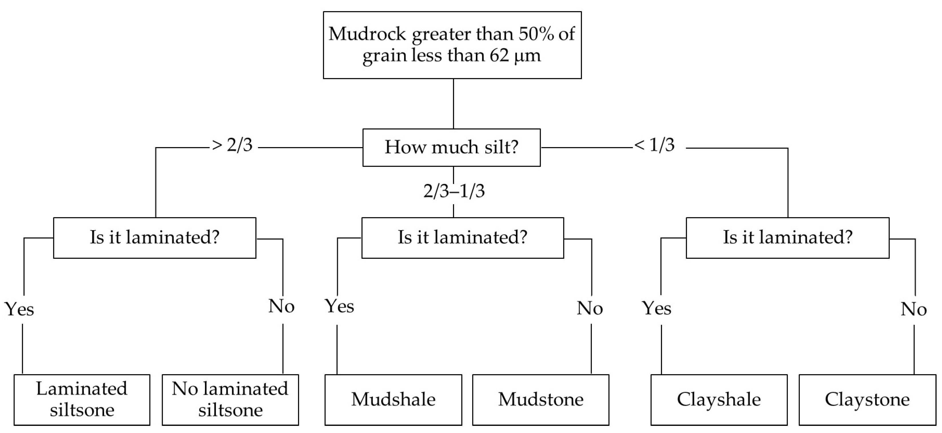
Following Potter et al.’s [
1] classification criteria, Lundegrad and Samuels [
6] advocated that laminated mudrocks with a percentage of silt less than 67% should be classified as ‘shale’, whereas rocks with a silt-sized fraction greater than this should be designated as siltstone, as shown in
Figure 1. Based on Potter et al.’s [
1] classification, Dick and Shakoor [
14] and Dick et al. [
21] recommended a boundary at 50% of clay to distinguish between mudstones and claystones as this reflects a change in the breakdown behaviour of mudrocks.
Several classifications have used the quartz or quartz plus feldspar percentages as criteria to distinguish between the different lithotypes of mudrocks [
11,
33,
55,
56,
57]. Boundaries were defined at 20% to differentiate between claystone and mudstone, at 40% to separate mudstone from siltstone, and at 60% to divide siltstone from sandstone. Quartz and quartz plus feldspar percentages may be determined by chemical and XRD procedures, and a correction factor must be applied to mudrocks with a carbonate content greater than 5% to account for the effect of dilution. Field criteria to distinguish mudrock lithotypes are provided in
Table 8.
Table 9 shows the rock classification presented in ISO 14689:2017 [
49], which delineates rock-like mudrocks as fine-grained clay-bearing rocks with quartz and feldspar grains less than 0.063 mm in size. The table includes the terms argillaceous, which means containing clay minerals, and lutaceous, which implies a material containing fine grains of silt- and/or clay-sized material. In accordance with ISO 14689:2017’s classification [
49], marlstone contains at least 50% of carbonate grains. Nevertheless, it is presumed that rocks containing less than 50% carbonate, as either grains or cement, will be classified as marlstone. ISO standards [
50,
51] help to identify, describe and classify soil-like mudrocks.
3.2. Engineering Geological Classifications
Attempts at engineering definitions of mudrock have been proposed by several authors [
55,
57,
58,
59,
60,
61,
62,
63], and a main concern in the classification of such materials is the division between soil and rock. The distinction between ‘compaction shales’, which are consolidated muddy sediments without intergranular cement, and ‘cemented shales’, which contain intergranular cement, was proposed by Mead [
58] and followed by Underwood’s classification [
59].
The latter was the first to distinguish the control of soil-like and rock-like properties on mudrock breakdown behaviour. Additionally, as pointed out by Cripps and Taylor [
7], induration, stress history, and weathering are factors that strongly influence engineering properties. Another approach to defining a soil/rock boundary is based on the strength characteristics of the materials [
55,
57,
60,
61,
62]. Commonly field strength criteria and laboratory testing, mainly uniaxial compressive strength (UCS) results, are used for this purpose (
Table 10).
However, it is recognized that there is no specific strength limit that is widely accepted as a soil/rock boundary, and there is a lack of standardization of the definition of weak rock, as different institutions and researchers suggested different UCS values [
33,
55,
57,
61,
62], and whether loading results in brittle or plastic deformation depends on the confining conditions and the rate of loading. In the range of mudrocks with low UCS values, the same material may be classified by different classifications as rock or as soil, with severe geotechnical and contractual consequences where such materials are involved in engineering works.
The increase of civil engineering works dealing with mudrocks as natural ground on construction and ground engineering sites and as made ground, fill, and construction material promoted the development of several classification schemes based on mechanical and engineering properties. Such classifications aim to provide criteria to deal with mudrocks in design studies and in the organization and management of the construction process.
Table 11 lists the soil/rock features and index tests selected for some of the most widely used classifications. Slake durability is adopted by several classifications to anticipate the breakdown behaviour of mudrocks. Plasticity is commonly adopted in schemes for less indurated materials, and strength (particularly uniaxial compressive strength and/or point load strength) are used to distinguish between soil-like and rock-like mudrocks as well as to subdivide the stronger types.
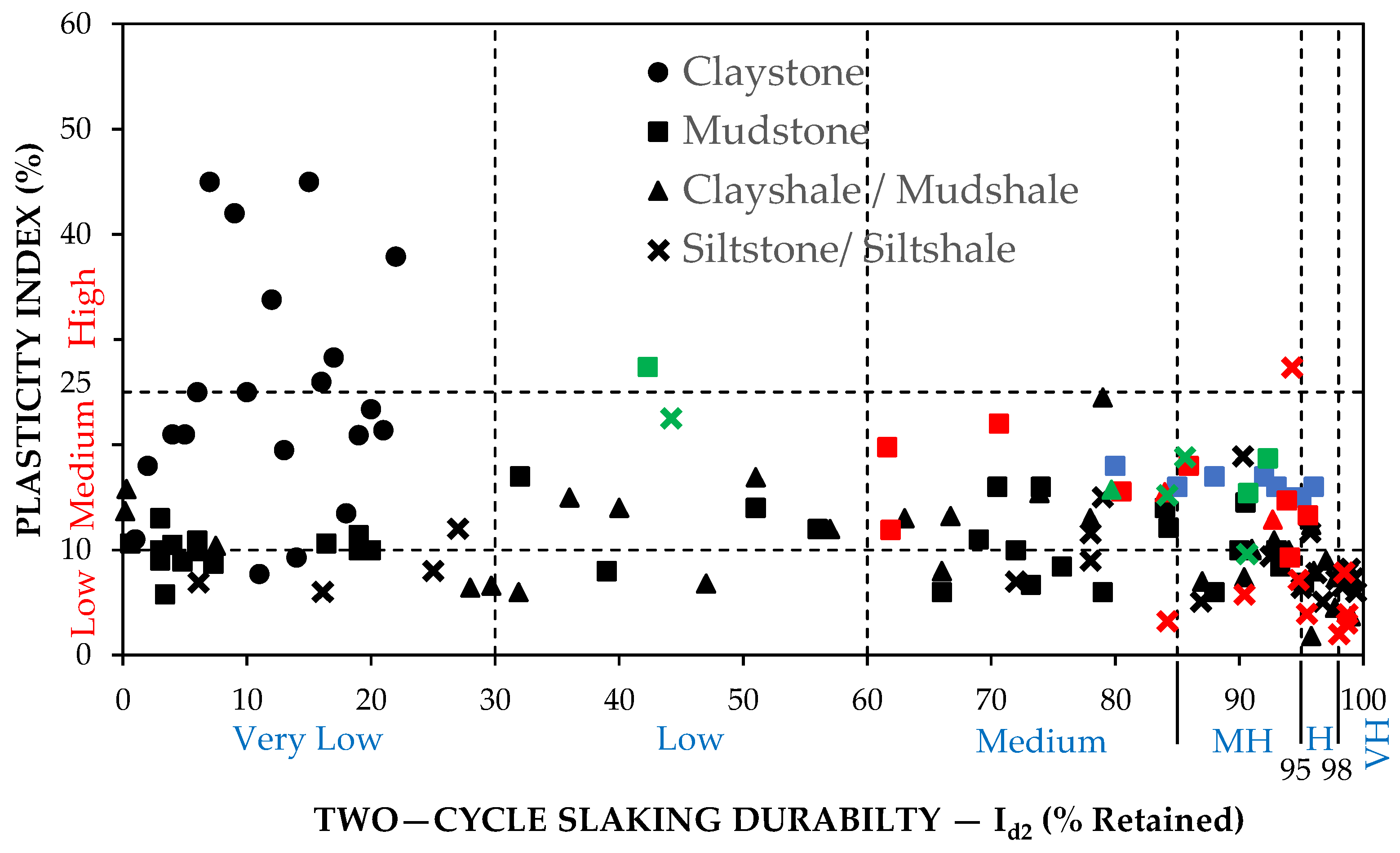
Gamble’s [
64] durability-plasticity classification of mudrocks, based on the plasticity index and two-cycle slake durability index, differentiates six durability classes and is suitable for less indurated mudrocks.
Figure 12 displays this classification for Portuguese, UK, North American, and Iranian mudrocks.
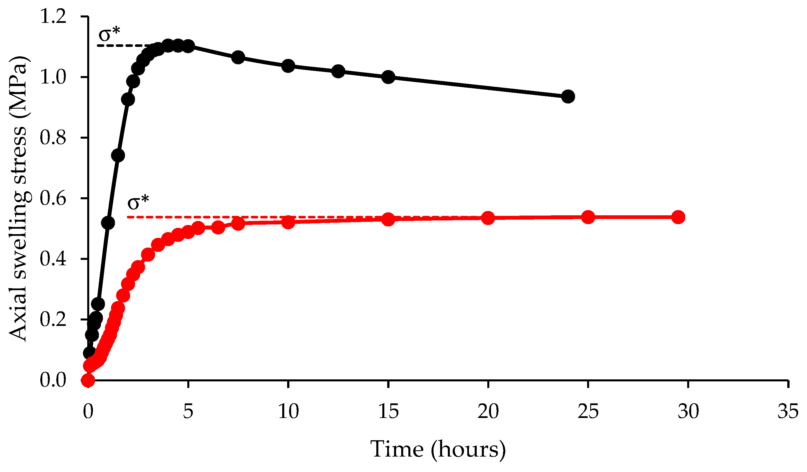
Morgenstern and Eigenbrod’s [
60] classification is based on a strength softening test, slaking test, rate of slaking, and liquid limit. Clays and mudstones are differentiated according to the results from the initial shear strength (c
uo) and strength loss (Δc
u) resulting from the immersion of the materials in water. Materials with c
uo values less than 1.8 MPa and Δc
u greater than 60% are classified as clays, while materials with c
uo values higher than 1.8 MPa and Δc
u less than 40% are classified as mudstone. However, the scheme proposed is time-consuming to apply, and only the part based on the rate of slaking and liquid limit is usually performed to estimate the potential for slaking [
65].
Table 11.
Soil and rock features and index tests adopted in some of most widely used mudrock engineering geological classifications [
11].
Table 11.
Soil and rock features and index tests adopted in some of most widely used mudrock engineering geological classifications [
11].
| Soil and Rock Characteristics and Index Tests | Classifications |
|---|
| Gamble [64] | Morg. and Eigen. [60] | Olivier [66,67] | Franklin [68] | Grainger [55] | Taylor [57] | Dick et al. [21] | Jeremias [11] | Czerewko and Cripps [43] | Erguler and Shakoor [40] | Ulusay and Erguler [69] |
|---|
| Mineralogy (from XRD analysis) | | | | | √ | √ | | | | | |
| Anisotropy (Flakiness ratio) | | | | | √ | | | | | | |
| Microfracture frequency index | | | | | | | √ | | | | √ |
| Dry density | | | | | | | | √ | | | |
| Grain size | | | | | √ | | | | | | |
| Absorption water | | | | | | | √ | | | | |
| Moisture absorption | | | | | | | | | √ | | |
| Atterberg limits | √ | √ | | √ | √ | | | | | | |
| Methylene blue adsorption value | | | | | | | | √ | √ | | |
| Uniaxial compressive strength | | | √ | | √ | √ | | | | | |
| Undrained Shear strength | | √ | | | √ | | | | | | |
| Point load strength | | | √ | √ | √ | √ | | | | | |
| Cone indenter number | | | | | √ | | | | | | |
| Free swelling strain | | | √ | | | | | | | | |
| Slake durability (evaluated by Jar Slake) | | √ | | | | | | | √ | | |
| Slake durability (evaluated from slake durability test) | √ | | | √ | √ | √ | √ | √ | | √ | |
| Rate of slaking | | √ | | | | | | | | | |
| Disintegration ratio | | | | | | | | | | √ | |
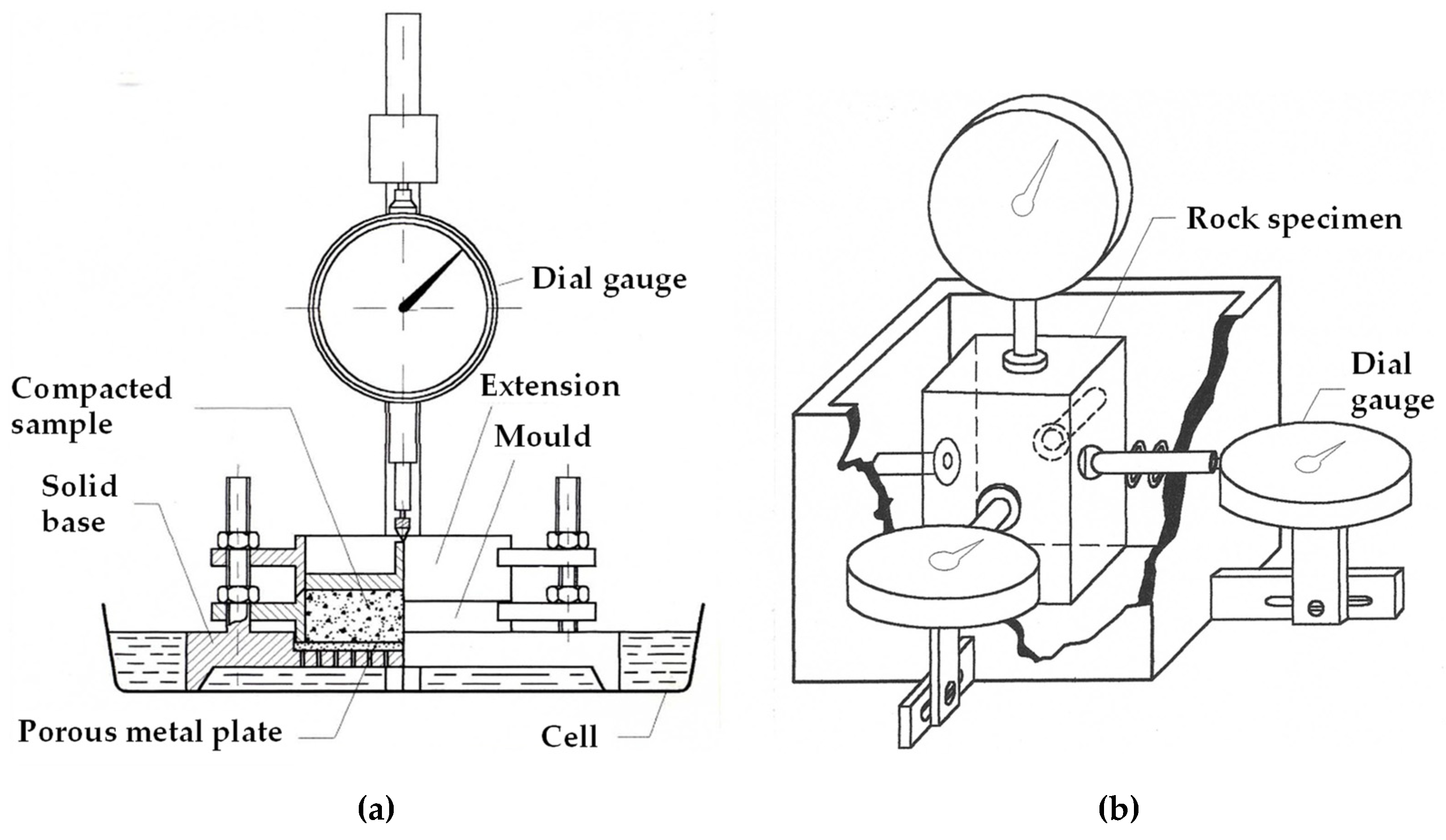
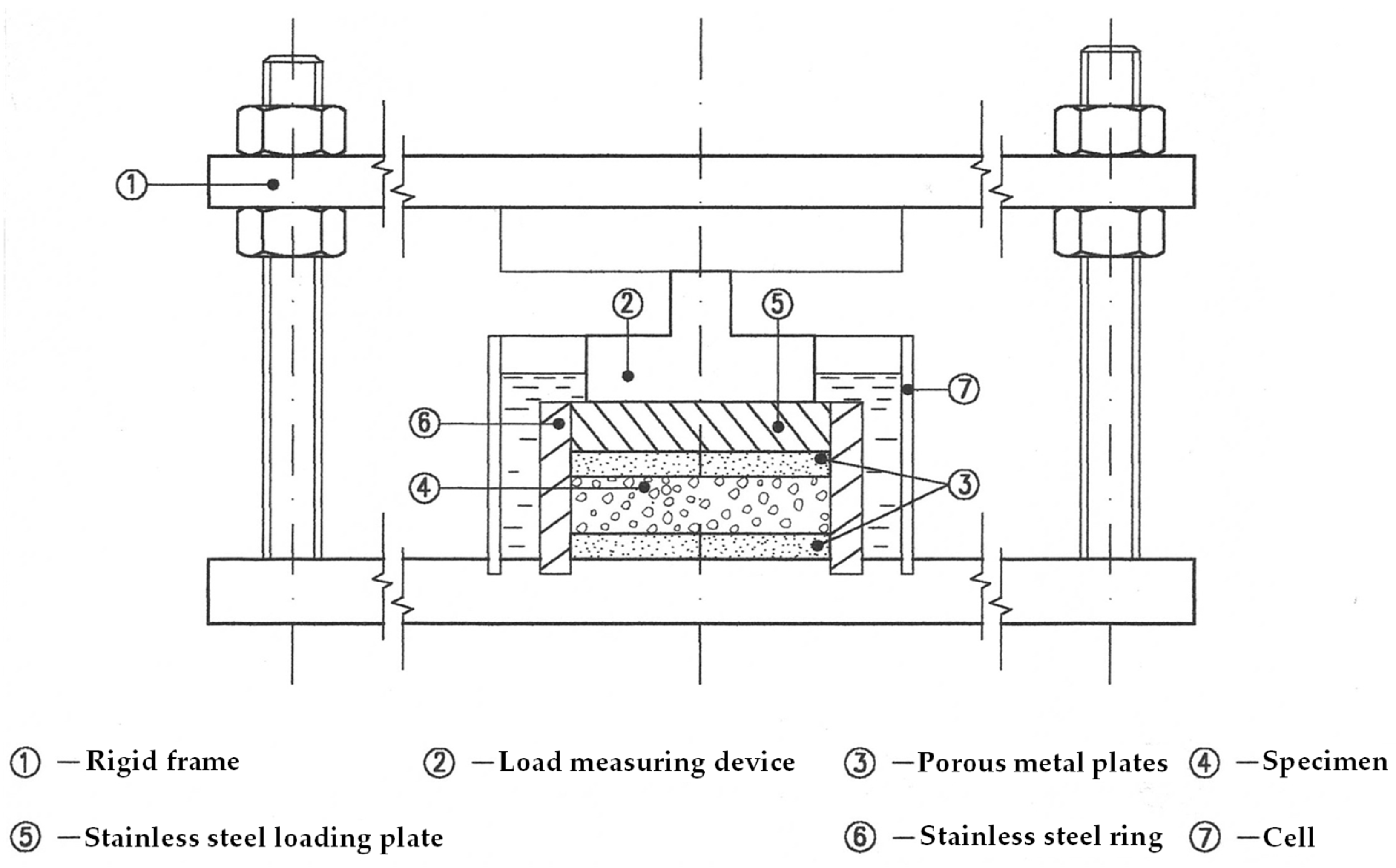
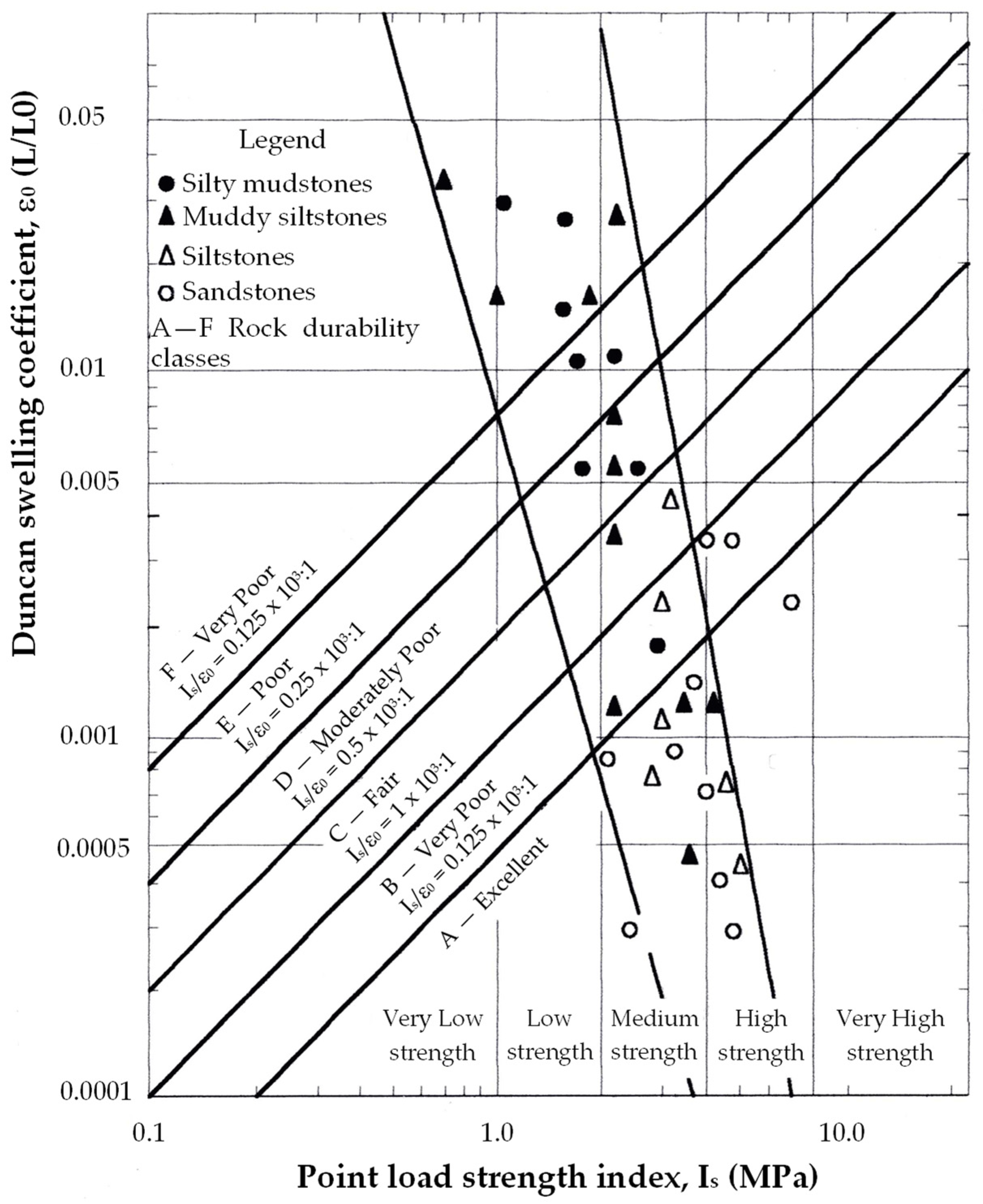
Olivier’s [
66,
67] geodurability classification is based on uniaxial compressive strength or point load strength and ‘Duncan’ free swelling coefficient (
Figure 13). This classification was developed for mudrocks of Karoo Supergroup, South Africa and six durability classes from very poor to excellent were recognized. According to Olivier [
67], the main drawback of this classification is that it is necessary to test a large number of samples to obtain representative values of the index parameters, which is challenging for less indurated mudrock types.
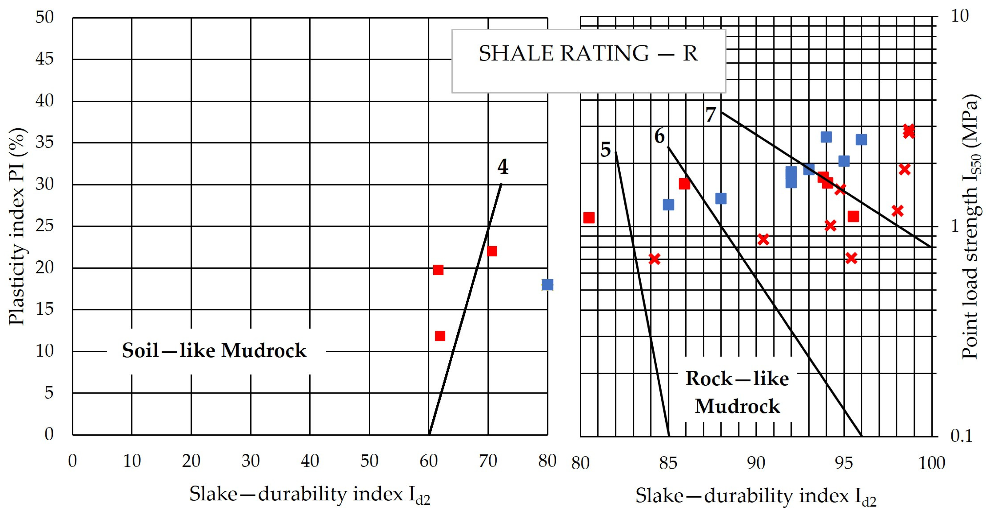
Franklin’s [
68] mudrock rating system is based on slake durability and plasticity index and point load strength, and it is suitable to classify both soil-like and rock-like mudrocks, which are distinguished from each other on the basis of a slake-durability index (I
d2) of 80%. For I
d2 values less than 80%, the mudrock is soil-like, and it is classified based on the results achieved by the slake durability test plus plasticity index (PI) and plotted in the left part of the chart in
Figure 14. If I
d2 values are greater than 80%, the mudrock is rock-like, and it is classified using slake durability and point load strength (I
S50), with the result plotted in the right part of the chart in
Figure 14.
Some correlations based on limited data between the mudrock rating-system values and aspects of the engineering performance of mudrocks observed in civil engineering works are provided by Franklin [
68].
Figure 14 shows Franklin’s mudrock rating system with some data for UK and Iranian mudrocks.
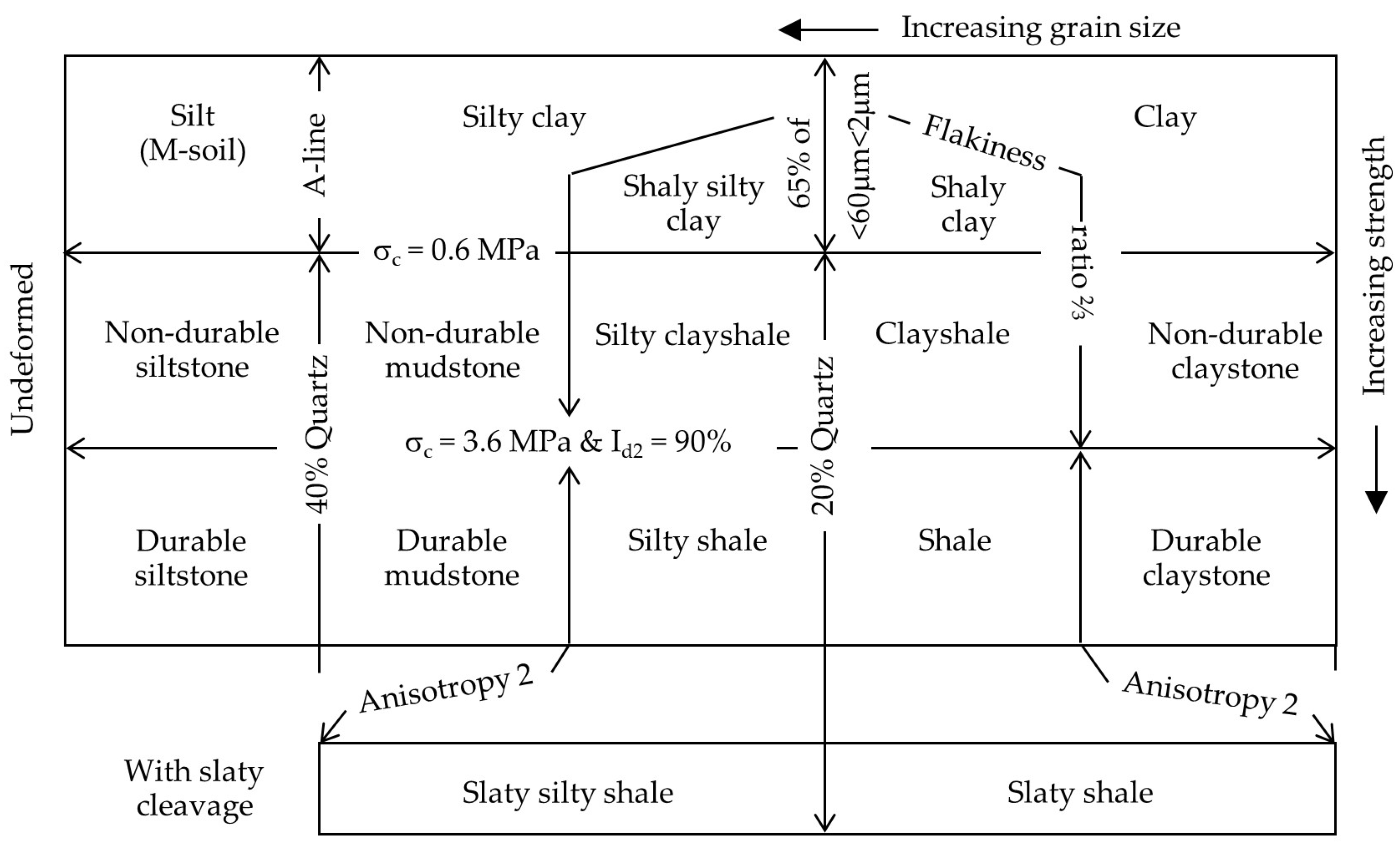
Grainger’s [
55] mudrock classification for engineering purposes in
Figure 15 is based on composition, uniaxial compressive strength, slake durability, and an anisotropy criterion. This classification uses some previous concepts, such as the quartz content to identify indurated mudrock lithotypes and Morgenstern and Eigenbrod’s [
60] strength criterion plus a slake durability index (I
d2) greater than 90% to differentiate durable and non-durable mudrocks. An assessment of anisotropic fabric is proposed to differentiate shale from non-shale lithotypes based on a flakiness ratio less than ⅔ for non-durable mudrocks and on a ratio between orthogonal strengths determined through point load or cone indenter testing greater than 2 for durable mudrocks.
Taylor’s [
57] mudrock classification is based on composition, uniaxial compressive strength, and slake durability. This classification also uses the quartz content method to distinguish between mudrock lithotypes, and this defines a mudrock as durable if UCS > 3.6 MPa and the 3-cycle slake durability index is greater than 60%.
Dick et al.’s [
21] mudrock durability classification is based on the lithological characteristics of the mudrocks. Accordingly, durability assessment should be achieved separately for claystones, mudstones, siltstones, shales, and argillites. They suggested that durability assessment of the different mudrock lithotypes may be determined from correlations between slake durability index (I
d2) and the amount of expandable clay minerals for claystones, the frequency of microfractures for mudstones, and water absorption value for both siltstones and shales.
Jeremias’s [
11] mudrock classification in
Table 12 is based on dry density, methylene blue adsorption value, and slake durability index.
The amount of void space and the nature and amount of clay minerals are two major parameters for mudrock durability assessment, evaluated by dry density and methylene blue index tests. Accordingly, data from Portuguese mudrocks were used to define a durability index (DI) determined from the scoring of the three index tests, each one on a scale 1 to 3, and thus, an overall rating between 3 and 9 may be obtained. Therefore, more durable mudrocks have rank values greater than 7, while non-durable materials have rank values less than 6 and an overall rating of between 3 and 9.
Czerewko and Cripps’s [
43] mudrock durability classification is based on the static slake test, moisture absorption, and the methylene blue value. This classification was developed using data from UK mudrocks, and each test was scored on a scale of 3 to 9 (Rank Total value).
Table 13 shows this classification which includes a description of sample evaluation and comments on durability behaviour expected in engineering situations are also provided [
70].
Erguler and Shakoor [
40] proposed a mudrock durability classification based on the disintegration ratio (D
R) and second-cycle slake durability index (I
d2) following the six classes defined in Gamble’s classification. Accordingly, the six categories of the Erguler and Shakoor’s classification are as follows: very low (I
d2 0–30%—D
R 0.00–0.19), low (I
d2 30–60%—D
R 0.20–0.49), medium (I
d2 60–85%—D
R 0.50–0.78), medium-high (I
d2 85–95%—D
R 0.79–0.91), high (I
d2 95–98%—D
R 0.92–0.95) and very high (I
d2 98–100%—D
R 0.96–1.00).
Erguler and Ulusay [
69] proposed a mudrock durability classification based on fracture frequency observed in the field and a newly defined index slake durability rating-SDR. A rating value of zero is assigned to the weakest rock material that disintegrates totally when subject to atmospheric process, and a rating of 100 is assigned to a material that does not show disintegration in the field. SDR is defined as SDR = 100–100λ where λ means fracture frequency, defined as the number of fractures per meter. For the Turkish rocks studied by these researchers, values ranging between 0 and 1 mm
−1 and up to 1 mm
−1 were obtained for the least durable material. A six-class classification based only on SDR value was proposed, and general information related to physical and mechanical properties as well as visual and verbal descriptions for each class, was provided.


