Technical Note

Effect of Rainfall Intensity on Landslide Initiation: Flume Tests and Numerical Analysis

School of Engineering and Built Environment, Griffith University, Southport, QLD 4222, Australia
*
Author to whom correspondence should be addressed.
Geotechnics 2023, 3(1), 104-115; https://doi.org/10.3390/geotechnics3010007
Submission received: 9 February 2023 / Revised: 16 March 2023 / Accepted: 16 March 2023 / Published: 17 March 2023

Abstract

:
This paper seeks to investigate the effect of rainfall intensity on the occurrence of shallow landslides by means of a series of flume tests. Coarse-grained material was used to build a slope, and several rainfall events with an intensity of either 40 mm/h, 70 mm/h, or 100 mm/h were simulated to initiate slope failure. A set of pore water pressure and moisture content sensors was installed in the slope to monitor changes in the water conditions during each test. Different initial moisture contents of 5% and 10% of the soil mass were used to better understand the effect of moisture on slope stability during rainfall. It was found that the slope failed when intensities of 70 mm/h and 100 mm/h were used; however, no failure was observed with a rainfall intensity of 40 mm/h. The failure patterns were found to be similar, with progressive slides occurring as more water infiltrated the slope. A numerical procedure to estimate the factor of safety over the period of the rainfall event was proposed and validated against the laboratory data. The results of the numerical analysis yielded the failure time, which was close to the time observed in the flume tests.

1. Introduction

Rainfall-induced shallow landslides are arguably the most common natural disaster that occur on natural slopes made of weathered material. Despite the relatively small size, these slides cause significant damage to infrastructure and cause economic losses to local communities. Several studies on this natural phenomenon [1,2,3,4], with more recent examples reported in Australia by Cogan et al. [5], Ravindran et al. [6], and Ravindran and Gratchev [7], have indicated that the failure typically occurs after prolonged rainfall events when a sufficient amount of pore water pressure is generated in the soil mass. Recent studies on landslides in Australia [5,6,7,8] show that the majority of shallow landslides occur in coarse-grained material, which is a product of weathering of the underlying bedrock. The failure generally takes place on a relatively steep slope inclined at 35–45° due to a high amount of rainfall.
There are different methods to investigate shallow landslides, including landslide hazard mapping, establishing rainfall thresholds associated with landslide activities, and laboratory examination of soil samples from the landslide mass. Additionally, small to large-scale flume tests have been utilized to investigate the landslide mechanism and estimate the effect of several factors on soil mass movements. In recent decades, a number of flume tests have been performed using large flume setups [9,10,11], different soil materials and initial soil properties [12,13,14,15,16], and different rainfall durations [17,18]. These papers only investigated the effect of individual factors such as slope geometry, soil type, and initial soil conditions on the occurrence of landslides. Recently, Cogan and Gratchev [19] summarized the recent advances in flume tests and experimentally showed the importance of each factor with respect to landslide occurrence. It was found that the rainfall intensity is the key factor in landslide initiation; therefore, its effect should be further investigated, especially in light of the climate change issue, as a result of which more frequent and extreme rainfall events are expected in the future [20,21].
Despite the obvious advantages of flume tests, they are rather costly, time-consuming, and labour-intensive. In addition, it remains unclear to what extent flume tests can simulate the behaviour of real-life landslide masses in the field. Nevertheless, flume tests represent a valuable tool that can be used by a range of researchers and practitioners to develop, calibrate, or refine the existing numerical models to predict slope failures.
This study investigates the effect of rainfall intensity on slope stability and proposes a numerical procedure that can be used to accurately predict the time of slope failure. In this paper, we present and discuss the results of a series of flume tests that simulated the initiation of rainfall-induced landslides under different rainfall patterns. Measurements of suction, pore water pressure, and soil water content were performed during each test to study the slope response to increasing rainfall intensities. The high-quality data from these tests helped to better understand the effect of rainfall intensity on the occurrence of shallow landslides and to explain the mechanism of landslide initiation. The obtained results were numerically analysed using a slope stability procedure originally proposed by Montrasio et al. [22] and modified by Ravindran and Gratchev [7]. The good agreement between the laboratory and numerical results suggests that this procedure can be used as a simplified tool to predict slope failures in the field; therefore, with some modifications according to local conditions, it can also be of interest to the international reader.

2. Materials and Methods

2.1. Material Used

Commercially available soil was used for flume tests. Soil grain size distribution was determined in accordance with Australian standard AS 1289.3.6.1 (2009). The specific gravity of soil was determined according to Australian standard AS 1289.3.5.1.
The soil consisted of 44% gravel, 54% sand, and 2% fines. This coarse-grained soil had a coefficient of uniformity (Cu) of 1.7, a coefficient of curvature (Cc) of 1.0, and a specific gravity (Gs) of 2.63.

2.2. Shear Box Tests

Direct shear tests (the size of the shear box was 60 mm × 60 mm) were performed according to AS 1289.6.2.2–1998 (Figure 1). The soil samples were oven-dried at 105 °C for 24 h, then passed through a 4.75 mm sieve. A series of shear box tests was performed on specimens at various moisture contents, ranging from 0 to 31% (Table 1). To allow for comparisons of the obtained results, all specimens were prepared with the same voids ratio (e = 0.55), a value which was used in the flume tests. The moist specimens were prepared by mixing the oven-dried soil with a certain amount of water. They were allowed to rest in a sealed bag for 24 h for more even saturation. Each soil specimen was compacted in the shear box in six layers to achieve the desirable void ratio value. The soil specimens were sheared under an effective vertical stress of either 28.5, 55.8, or 83.0 kPa. The peak shear stress was recorded and used to determine the strength characteristics of each soil.
A summary of the shear box tests is given in Table 1. It is evident that the shear strength of soil decreased as the initial moisture content increased. This change in soil strength can largely be seen in the decreased values, with the apparent cohesion dropping from 27 kPa (at moisture content of 2%) to 0 at a moisture content of 31%. There is a negligible change in the friction angle, a finding that agrees with previous research [23] on shear strength of soil at different water contents.

2.3. Flume Apparatus and Experimental Setup

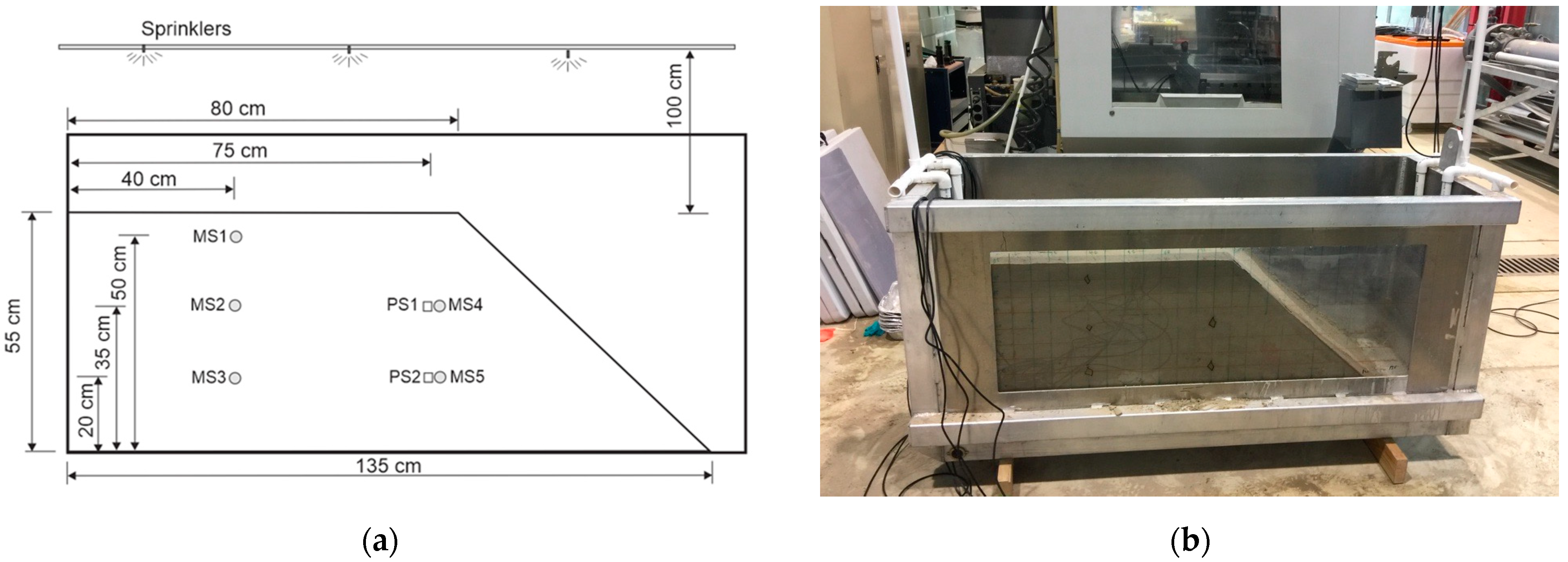
The flume tank was 1.5 m long, 0.83 m high, and 0.63 m wide (Figure 2a). Plexiglas was used as one of the walls to enable visual observation of soil mass during simulated rainfall events (Figure 2b). The sand was placed in the tank in six layers and uniformly compacted to achieve the desired voids ratio value (e = 0.55) and a slope geometry of 40°, as shown in Figure 2a,b. For each rainfall intensity, two values of water content were used, i.e., 5% and 10%, representing field conditions as reported by Cogan et al. [5]. It is noted that due to the mixing of large amounts of sand and water, it was rather difficult to obtain the exact water content for each experiment.
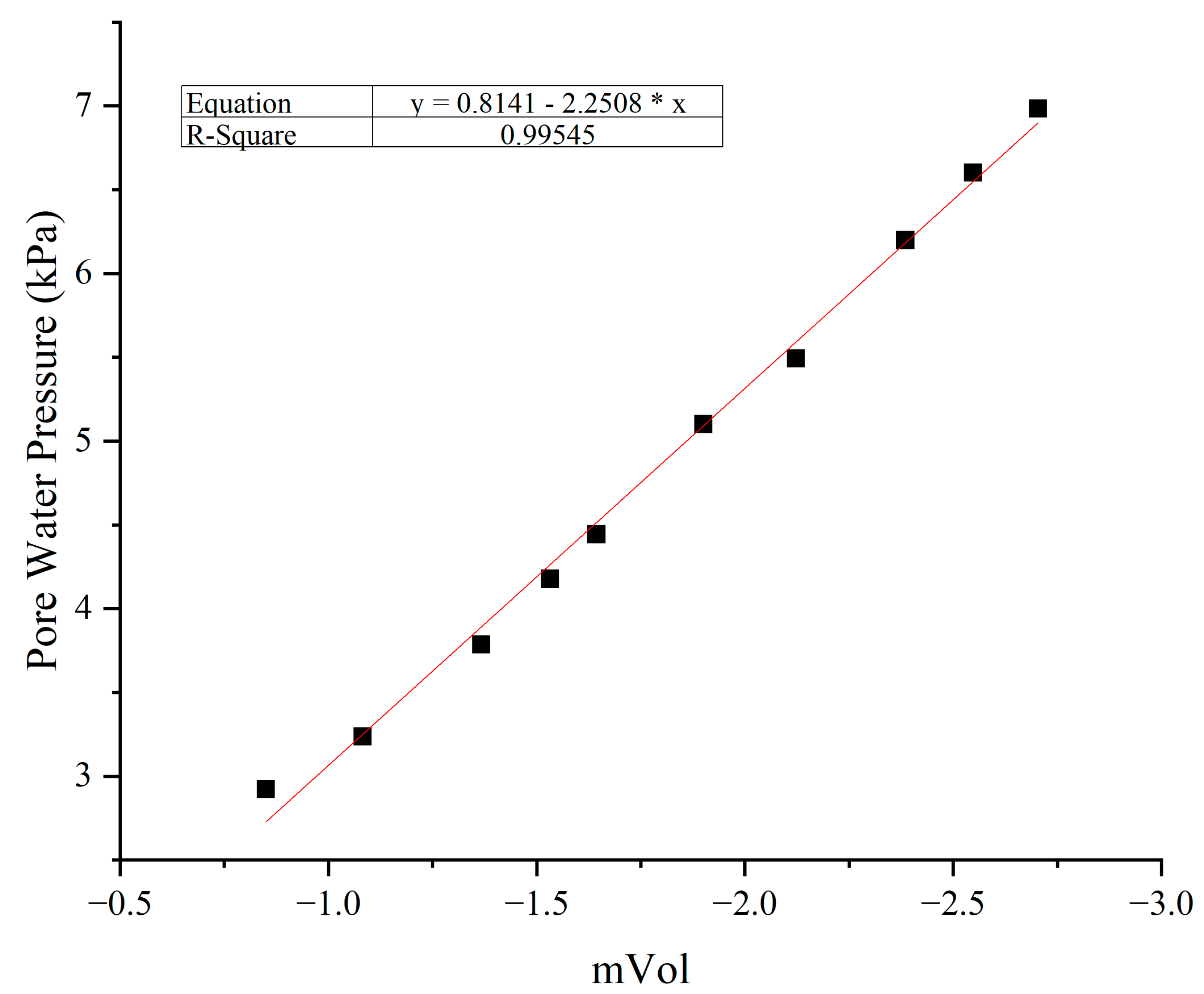
The water content was measured in 5 different locations (MS1 to MS5), as schematically shown in Figure 2a, to obtain a better idea of moisture distribution in the whole slope during a rainfall event. The water content sensors were commercially available MP306 sensors. Pore water pressure sensors (T5) with a capacity of −85 to 100 kPa were used to measure the changes in soil suction and pore water pressure generation (PS1 and PS2 in Figure 2a). The sensor was carefully calibrated before each experiment, and the accuracy was verified by detecting the current variation of the sensor data in water at different depths in relation to the actual pressure. Figure 3 shows a typical calibration curve with an error of less than 1.0%.
Mist sprinklers suspended over the tank were used to simulate a rainfall event and to avoid surface erosion, which is a common technical issue in such experiments. Before the test, the sprinklers were calibrated to produce rainfall with the desired rainfall intensity of either 40 mm/h, 70 mm/h, or 100 mm/h. These alterations in the rainfall intensity and the initial moisture content made for a total of 6 flume experiments performed. Changes in the pore water pressure and water content were recorded automatically by means of a data logger and computer. Video recording was conducted throughout the test to monitor surface movements and slope failure. Failure was defined and determined through video footage and visual observations as the slope deformed.

3. Results and Discussion

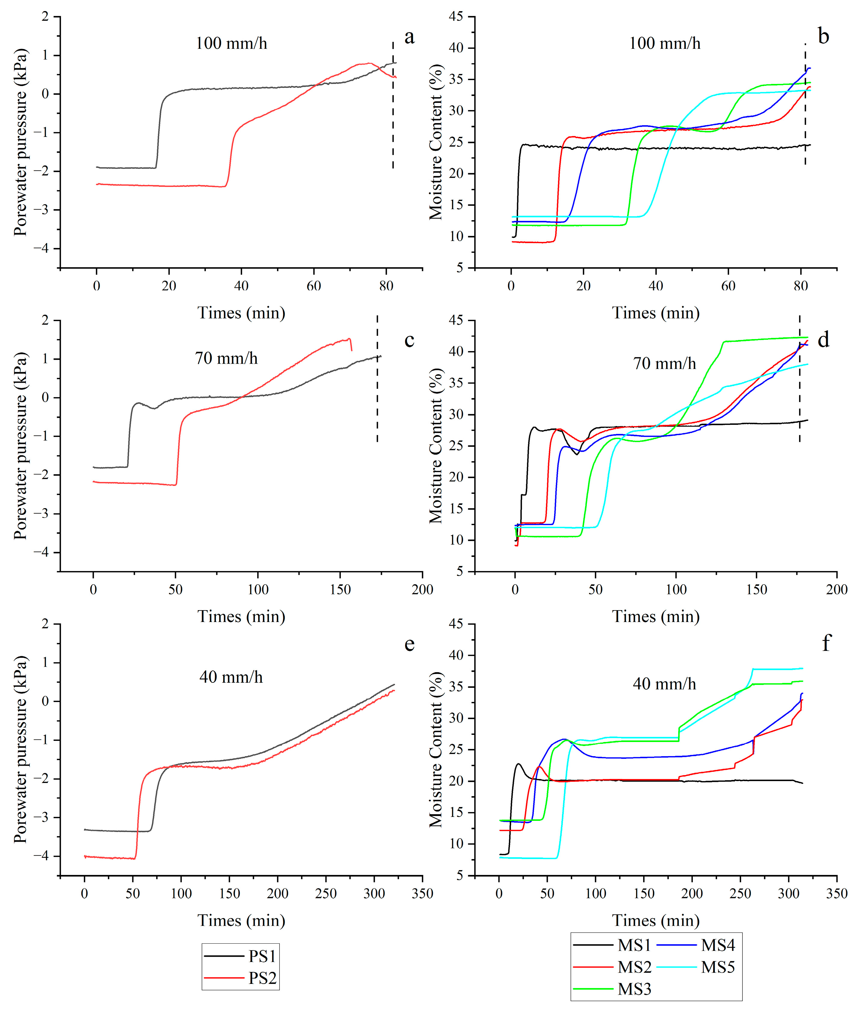
Results from a series of flume tests with different rainfall intensities are given in Figure 4 plotted as the time series data of pore water pressure (Figure 4a,c,e) and water content (Figure 4b,d,f). As can be seen in Figure 4a,c,e, in the beginning of each test, negative pore water pressure (i.e., suction) existed in the soil mass. However, as the rainfall simulation continued, water infiltration in the soil mass increased, and the pore water pressure began to build up. The PS1 sensor located near the surface responded faster than the PS2 sensor, which was placed near the bottom of the slope. This behaviour was observed for all flume experiments in spite of different rainfall intensities. It is noted that the changes in pore water pressure occurred more rapidly for the greatest rainfall rate of 100 mm/h.
During each test, an increase in the water content was recorded as shown in Figure 3b,d,f. Changes in the water content occurred more rapidly for the rainfall intensity of 100 mm/h compared to the lowest intensity of 40 mm/h. However, the general pattern was almost the same for all flume tests; that is, the greater water content was recorded at the bottom of the slope. Due to gravity, excess water accumulated at the bottom of the slope, creating a wetting front that began to spread upward as more water infiltration occurred. Such behaviour of the wetting front in flume tests was reported by Cogan and Gratchev (2019), and to a certain extent, it may represent the change in ground water level in soil mass during prolonged rainfall under field conditions. The obtained data revealed common patterns of water flow in the whole slope. For each test, the water infiltration was first recorded at the top of the slope using the MS1 sensor, gradually proceeding to the middle of the slope (MS2 and MS3 sensors) and finally coming in contact with the MS3 and MS5 sensors, which were located at the bottom of the slope. Gradual changes in soil saturation were observed using the water content sensors as the water first infiltrated from the top to the bottom, then began to accumulate. The largest changes in the water content occurred at the bottom, then in the middle of the slope. Relatively smaller changes in the water content were recorded by the MS1 sensor, indicating that the uppermost part of the soil slope was not fully saturated.
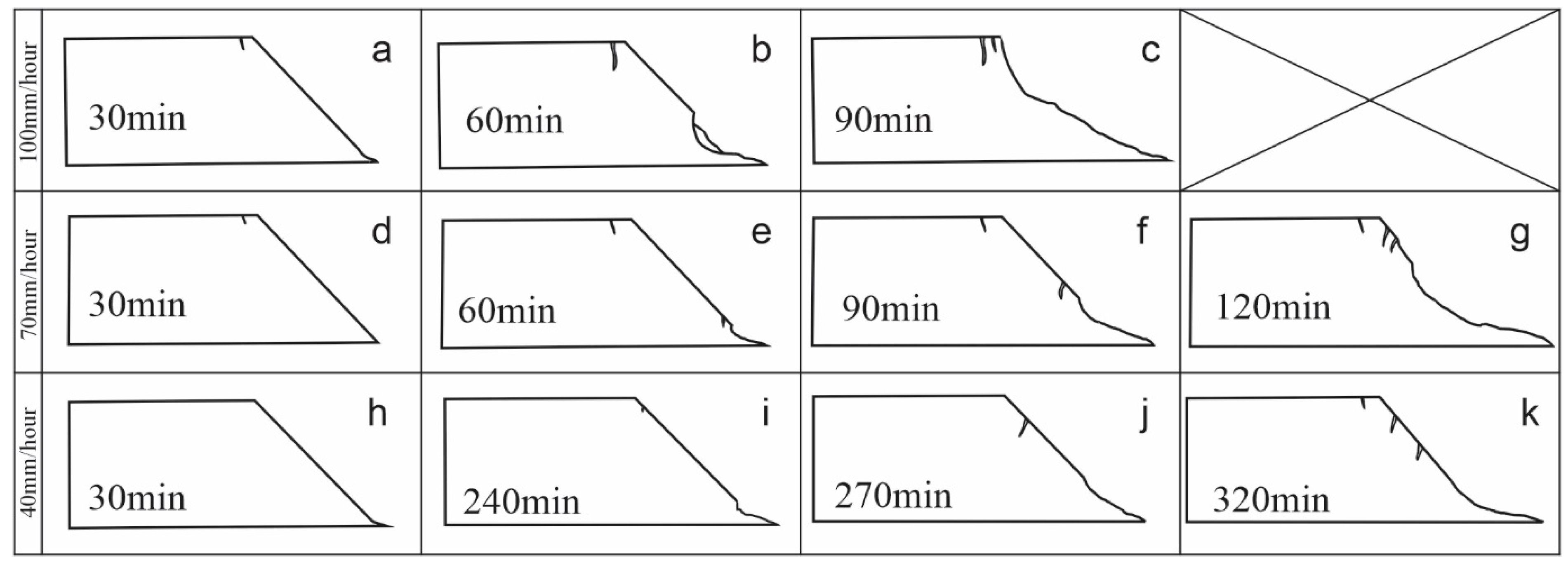
Visual observations during testing enabled better understanding of the mechanism of landslide initiation. For higher rainfall intensities, such as 70 and 100 mm/h, the failure pattern was related to the erosion caused by the water seeping through the granular sand. It started with a crack that appeared at the crest of the slope (Figure 5a for 100 mm/h and Figure 5d for 70 mm/h). It was observed that as the water content of soil mass increased, the excess water began to wash out sand particles at the toe of the slope (Figure 5b and Figure 5e, respectively), which led to larger surface collapses (Figure 5c,g). As can be seen in Figure 5b,e, the failure initiated at the toe, followed by the appearance of cracks near the slope crest. As more soil eroded, greater parts of slope collapsed.
For the relatively low rainfall intensity of 40 mm/h, the test continued for as long as 320 min. However, few cracks appeared during testing (Figure 5i,j), and no significant failure other than minor surface erosion took place by the end of the test (Figure 5k).
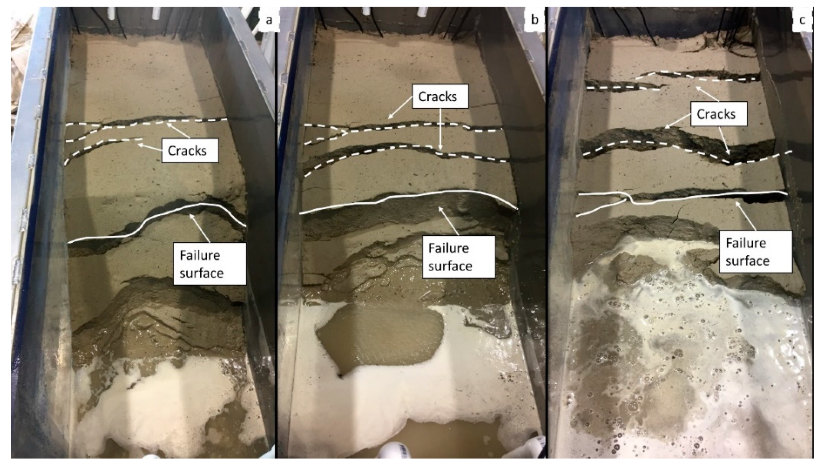
Figure 6 shows typical failure patterns that were observed in the flume experiments with rainfall intensities of 70 mm/h and 100 mm/h. After the initial failure occurred (Figure 6a), another failure took place within 20 min for the rainfall intensity of 70 mm/h and about 6 min for the rainfall intensity of 100 mm/h (Figure 6b). As the experiment continued, more crest cracks appeared, leading to the third progressive failure (Figure 6c).

4. Numerical Analysis

In this section, the laboratory data from the flume tests is compared with the results of numerical analysis, as originally proposed by Montrasio [22] and later modified by Ravindran and Gratchev [7].

4.1. Theoretical Considerations

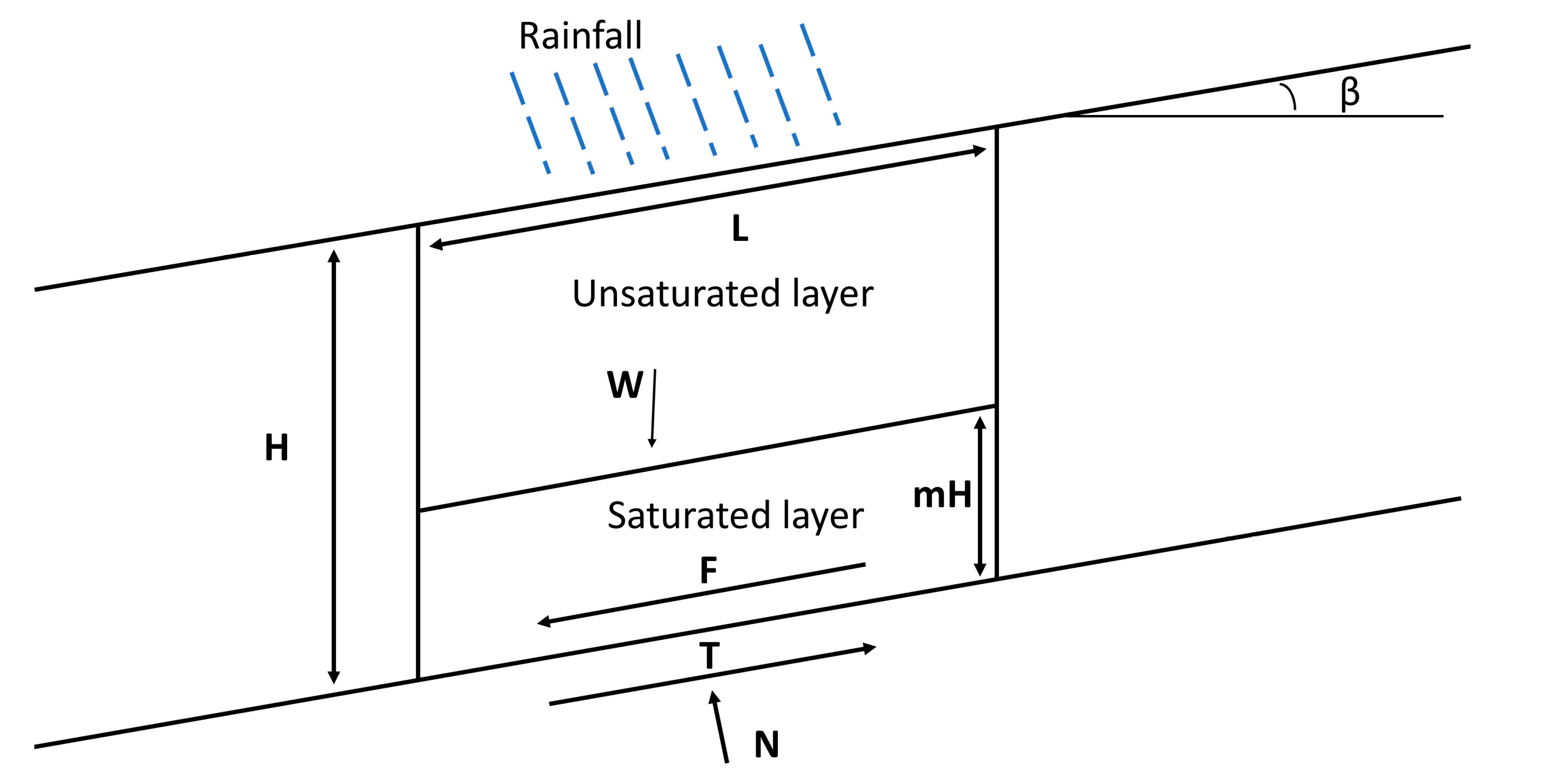
In this theoretical model (Figure 7), the potential landslide mass is divided into two parts: a saturated layer at the bottom and an unsaturated layer near the surface. The boundary between these two layers is defined by a parameter called m, which can vary over time depending on the amount and intensity of a rainfall event. The saturated layer is represented by mH, where 0 < m < 1, and H is the height of the slice, as shown in Figure 7. The unsaturated layer thickness is calculated as (1 − m)H. The parameter mH depends on the total amount of rainfall (h) and the soil degree of saturation (Sr) [24], as shown in Equation (1).
m H = ( β * x h ) / n ( 1 S r )
where β * is the percentage of rainfall that infiltrates into the soil, and n is the soil porosity. To estimate the shear strength of the soil (τ), Equations (2) and (3), which describe the Mohr–Coulomb failure criterion for unsaturated soils [25,26], are used.
τ = c + σ t a n + c ψ = σ t a n + C
C = c + c ψ
where c is the effective cohesion, σ is the effective normal stress, and c ψ is the apparent cohesion. The apparent cohesion ( c ψ ), which typically exists in unsaturated soil, depends on the matric suction and can be estimated using the degree of saturation ( S r ) [27]. To estimate the friction angle and apparent cohesion of the soil used in the flume tests, a series of shear box tests was conducted.
Previous studies suggested that for saturated conditions, the amount of matric suction in soil drops to 0, and so does the apparent cohesion. Montrasio et al. [25] developed Equations (4) and (5) to account for changes in the soil strength during a rainfall event when the soil mass gradually becomes saturated. These equations can be used to estimate the variation in apparent cohesion of soil mass with respect to m.
c ψ * = A S r ( 1 S r ) λ
where c ψ * is the ancillary parameter; A is the model parameter, which depends on the type of soil; and λ is the constant for a wide range of soil, with a recommended value of 0.4. It is noted that for saturated soil (when Sr = 1), c ψ * becomes zero.
c ψ = c ψ * ( 1 m ) α
where α is the model parameter and equals to 3.4 [24]. To estimate the factor of safety (FS) using the limit equilibrium method, Montrasio and Valentino (2008) established Equations (6)–(11) as noted below:
F S = ( c o t β x tan Г + m n w 1 + C x Ω ) / ( Г + m x n w )
Г = G s x 1 n + n x S r
C = c + c ψ x L
m = β * n H 1 S r x i = 1 w h i x e x p ( k t t t i )
n w = n x 1 S r
Ω = 2 / ( sin 2 β x H x γ w )
where k t is the coefficient of permeability, and γ w is the unit weight of water.

4.2. Comparison of Flume Test Results and Numerical Data

The input parameters for the numerical model with the references on how they were obtained are provided in Table 2. The fundamental properties of the specimens were obtained by laboratory tests. The parameters of the model were obtained through empirical formulas and according to the results of previous studies [7,22].
The results from the shear box test (Table 1) were utilized to estimate model parameter A using Excel Solver and following the procedure described by Ravindran and Gratchev [7]. Parameter A was calculated using the principle of optimisation by comparing actual values of apparent cohesion from the shear box test with the estimated value of apparent cohesion from Equation (3).
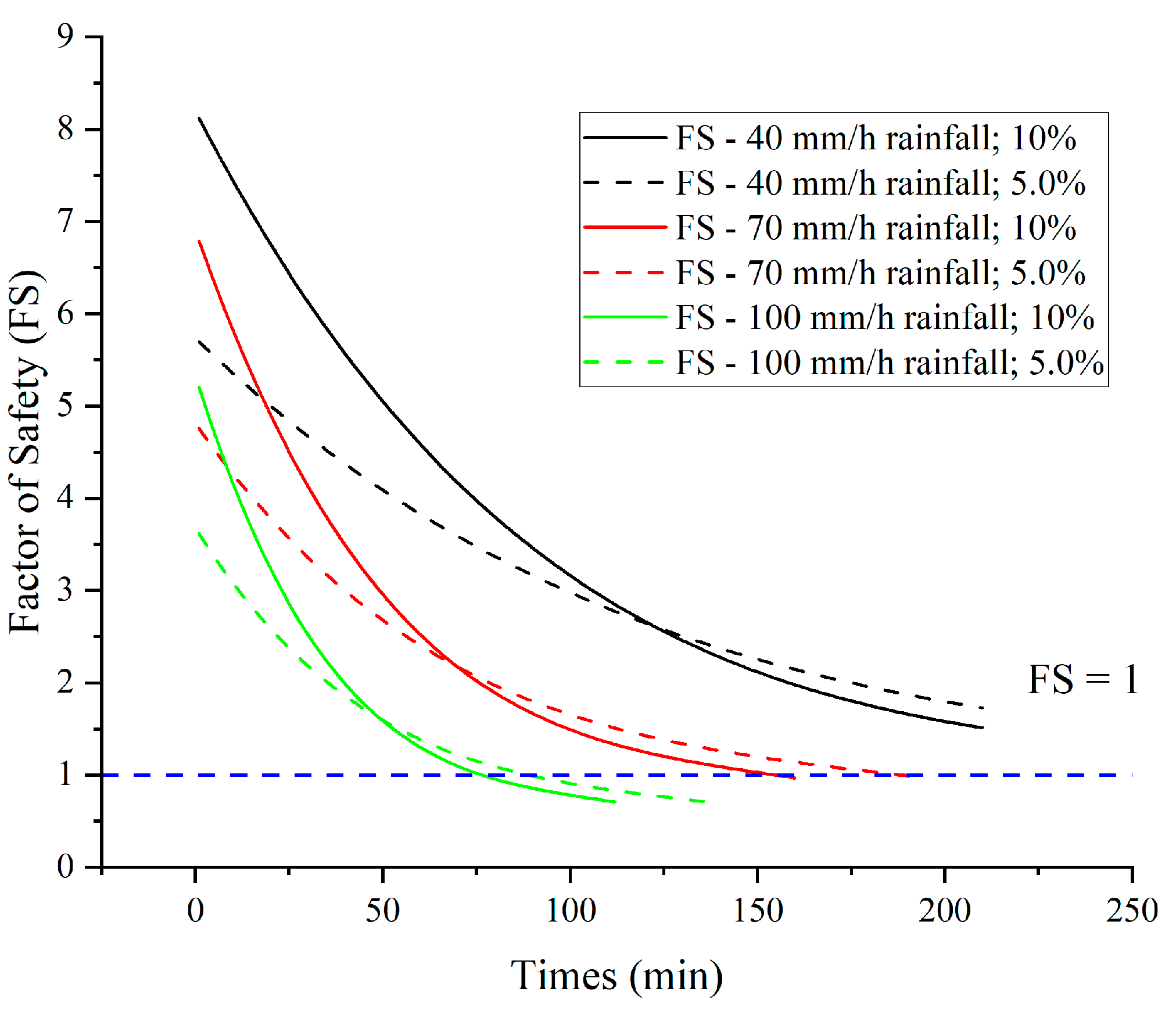
The outcome of the numerical analysis was the factor of safety (FS) obtained for each rainfall intensity and the initial moisture content. The change in FS over time for each simulated rainfall event is given in Figure 8. In this numerical analysis, when FS became less than one, slope failure was considered to occur. The time to reach failure for each rainfall intensity is given in Table 3.
It can be seen from Figure 8 that when the rainfall intensity increased, the FS tended to decrease more rapidly. In addition, when the initial moisture content increased from 5% to 10%, the time to reach failure decreased. The results of the numerical analysis seem to agree with the experimental data from the flume tests.
Table 3 provides a comparison of the actual time of slope failure in the flume tests with the predicted time from the numerical model. The predicted time was very similar to the actual failure time, especially for the rainfall intensity of 100 mm/h. The numerical procedure estimated the factor of safety for the rainfall intensity of 40 mm/h to be greater than 1 (that is, no failure), which is in agreement with the laboratory results. There seems to be relatively good prediction of the failure time for the rainfall intensity of 100 mm/h, while there are greater errors between the predicted and observed time for the rainfall intensity of 70 mm/h.

4.3. Limitations of the Numerical Model

It is noted that although good agreement between the laboratory results and numerical data was obtained, there are still some limitations related to the use of numerical procedures to predict landslide occurrence. Two types of problems can be highlighted here: the first is related to the inherent complexity of the triggering mechanisms of shallow landslides, while the second is linked to several limitations in simplifying this phenomenon through model-based approaches [28]. For instance, there are differences in the amount of precipitation required to trigger landslides of similar engineering nature in different areas [29]. In addition, the geological conditions at individual landslide sites can be complex and variable; however, the numerical procedures tend to assume the soil conditions to be uniform and homogeneous. Neglecting geological features may also result in errors in the accuracy of predictions [28]. However, the proposed numerical model provides reasonable estimations of the time to failure, and it can be used as a simplified tool to estimate the effect of prolonged rainfall events on the stability of natural slopes.

5. Conclusions

A series of flume tests was conducted on coarse-grained soil to investigate the effect of rainfall intensity and the initial moisture content of the soil mass upon initiation of shallow landslides. A numerical analysis was conducted to better understand the effect of rainfall on the slope stability and to compare the numerical data with the experimental outcomes. Based on the obtained results, the following conclusions can be drawn.
The rainfall intensity has a strong influence on landslide initiation. It was found that a relatively low rainfall intensity of 40 mm/h was not sufficient to trigger failure, while much greater rainfall intensities such as 70 mm/h and 100 mm/h led to relatively rapid slope failure.
Wetting front propagation during a rainfall event caused the change in water conditions in the soil slope from the suction to the pore water pressure build-up. An increase in the moisture content was observed in all flume experiments, while the greatest value of moisture content was first recorded at the bottom of the slope.
An increase in the initial moisture content of the soil mass resulted in more rapid slope failure. This was observed for both rainfall intensities of 70 mm/h and 100 mm/h.
The results of the numerical analysis agreed relatively well with the experimental data in terms of the failure time. This implies that the numerical procedure presented in this study has the potential to accurately estimate the time of failure and can be used as a simplified tool to predict large slope failures in the field triggered by rainfall events with different rainfall intensities and durations.

Author Contributions

Conceptualization, Q.T., S.R. and I.G.; methodology, Q.T. and S.R.; software, Q.T. and S.R.; validation, Q.T. and I.G.; formal analysis, Q.T. and S.R.; investigation, Q.T.; resources, I.G.; data curation, Q.T.; writing—original draft preparation, Q.T. and I.G.; writing—review and editing, I.G.; visualization, Q.T.; supervision, I.G.; project administration, I.G.; funding acquisition, I.G. All authors have read and agreed to the published version of the manuscript.

Funding

This research received no external funding.

Institutional Review Board Statement

Not applicable.

Informed Consent Statement

Not applicable.

Data Availability Statement

The data that support the findings of this study are available from the corresponding author upon reasonable request.

Conflicts of Interest

The authors declare no conflict of interest.

References

  1. Dai, F.C.; Lee, C.F.; Li, J.; Xu, Z.W. Assessment of landslide susceptibility on the natural terrain of Lantau Island, Hong Kong. Environ. Geol. 2001, 40, 381–391. [Google Scholar] [CrossRef]
  2. Cascini, L.; Cuomo, S.; Della Sala, M. Spatial and temporal occurrence of rainfall-induced shallow landslides of flow type: A case of Sarno-Quindici, Italy. Geomorphology 2011, 126, 148–158. [Google Scholar] [CrossRef]
  3. Lepore, C.; Kamal, S.A.; Shanahan, P.; Bras, R.L. Rainfall-induced landslide susceptibility zonation of Puerto Rico. Environ. Earth Sci. 2012, 66, 1667–1681. [Google Scholar] [CrossRef]
  4. Zhang, S.; Zhang, L.M.; Glade, T. Characteristics of earthquake- and rain-induced landslides near the epicenter of Wenchuan earthquake. Eng. Geol. 2014, 175, 58–73. [Google Scholar] [CrossRef]
  5. Cogan, J.; Gratchev, I.; Wang, G. Rainfall-induced shallow landslides caused by ex-Tropical Cyclone Debbie, 31st March 2017. Landslides 2018, 15, 1215–1221. [Google Scholar] [CrossRef]
  6. Ravindran, S.; Gratchev, I.; Jeng, D.S. Analysis of Rainfall-Induced Landslides in Northern New South Wales, Australia. Aust. Geomech. 2019, 54, 83–97. [Google Scholar]
  7. Ravindran, S.; Gratchev, I. Prediction of Shallow Rainfall-Induced Landslides Using Shear Strength of Unsaturated Soil. Indian Geotech. J. 2021, 51, 661–672. [Google Scholar] [CrossRef]
  8. Gratchev, I.; Ravindran, S.; Kim, D.H.; Cui, C.; Tang, Q. Mechanisms of Shallow Rainfall-Induced Landslides from Australia: Insights into Field and Laboratory Investigations; Springer International Publishing: Berlin/Heidelberg, Germany, 2023; pp. 113–122. [Google Scholar]
  9. Okura, Y.; Kitahara, H.; Ochiai, H.; Sammori, T.; Kawanami, A. Landslide fluidization process by flume experiments. Eng. Geol. 2002, 66, 65–78. [Google Scholar] [CrossRef]
  10. Moriwaki, H.; Inokuchi, T.; Hattanji, T.; Sassa, K.; Ochiai, H.; Wang, G. Failure processes in a full-scale landslide experiment using a rainfall simulator. Landslides 2004, 1, 277–288. [Google Scholar] [CrossRef]
  11. Olivares, L.; Damiano, E.; Greco, R.; Zeni, L.; Picarelli, L.; Minardo, A.; Guida, A.; Bernini, R. An Instrumented Flume to Investigate the Mechanics of Rainfall-induced Landslides in Unsaturated Granular Soils. Geotech. Test. J. 2009, 32, 108–118. [Google Scholar]
  12. Wang, G.; Sassa, K. Factors affecting rainfall-induced flowslides in laboratory flume tests. Geotechnique 2001, 51, 587–599. [Google Scholar] [CrossRef]
  13. Wang, G.H.; Sassa, K. Pore-pressure generation and movement of rainfall-induced landslides: Effects of grain size and fine-particle content. Eng. Geol. 2003, 69, 109–125. [Google Scholar] [CrossRef]
  14. Lourenço, S.D.N.; Sassa, K.; Fukuoka, H. Failure process and hydrologic response of a two layer physical model: Implications for rainfall-induced landslides. Geomorphology 2006, 73, 115–130. [Google Scholar] [CrossRef]
  15. Hakro, M.R.; Harahap, I.S.H. Laboratory experiments on rainfall-induced flowslide from pore pressure and moisture content measurements. Nat. Hazards Earth Syst. Sci. Discuss. 2015, 3, 1575–1613. [Google Scholar] [CrossRef]
  16. Wu, L.Z.; Huang, R.Q.; Xu, Q.; Zhang, L.M.; Li, H.L. Analysis of physical testing of rainfall-induced soil slope failures. Environ. Earth Sci. 2015, 73, 8519–8531. [Google Scholar] [CrossRef]
  17. Acharya, G.; Cochrane, T.A.; Davies, T.; Bowman, E. The influence of shallow landslides on sediment supply: A flume-based investigation using sandy soil. Eng. Geol. 2009, 109, 161–169. [Google Scholar] [CrossRef]
  18. Ahmadi-Adli, M.; Huvaj, N.; Toker, N.K. Rainfall-triggered landslides in an unsaturated soil: A laboratory flume study. Environ. Earth Sci. 2017, 76, 735. [Google Scholar] [CrossRef]
  19. Cogan, J.; Gratchev, I. A study on the effect of rainfall and slope characteristics on landslide initiation by means of flume tests. Landslides 2019, 16, 2369–2379. [Google Scholar] [CrossRef]
  20. Gariano, S.L.; Guzzetti, F. Landslides in a changing climate. Earth-Sci. Rev. 2016, 162, 227–252. [Google Scholar] [CrossRef] [Green Version]
  21. O’Neill, B.C.; Oppenheimer, M.; Warren, R.; Hallegatte, S.; Kopp, R.E.; Portner, H.O.; Scholes, R.; Birkmann, J.; Foden, W.; Licker, R.; et al. IPCC reasons for concern regarding climate change risks. Nat. Clim. Chang. 2017, 7, 28–37. [Google Scholar] [CrossRef] [Green Version]
  22. Montrasio, L.; Valentino, R.; Losi, G.L. Rainfall-induced shallow landslides: A model for the triggering mechanism of some case studies in Northern Italy. Landslides 2009, 6, 241–251. [Google Scholar] [CrossRef]
  23. Ravindran, S.; Gratchev, I. Effect of Water Content on Apparent Cohesion of Soils from Landslide Sites. Geotechnics 2022, 2, 385–394. [Google Scholar] [CrossRef]
  24. Montrasio, L.; Valentino, R. A model for triggering mechanisms of shallow landslides. Nat. Hazards Earth Syst. Sci. 2008, 8, 1149–1159. [Google Scholar] [CrossRef]
  25. Montrasio, L.; Valentino, R.; Meisina, C. Soil Saturation and Stability Analysis of a Test Site Slope Using the Shallow Landslide Instability Prediction (SLIP) Model. Geotech. Geol. Eng. 2018, 36, 2331–2342. [Google Scholar] [CrossRef]
  26. Fredlund, D.G.; Rahardjo, H. Soil Mechanics for Unsaturated Soils; John Wiley & Sons: New York, NY, USA, 1993. [Google Scholar]
  27. Fredlund, D.G.; Xing, A.Q.; Fredlund, M.D.; Barbour, S.L. The relationship of the unsaturated soil shear strength to the soil-water characteristic curve. Can. Geotech. J. 1996, 33, 440–448. [Google Scholar] [CrossRef]
  28. Montrasio, L.; Valentino, R.; Losi, G.L. Towards a real-time susceptibility assessment of rainfall-induced shallow landslides on a regional scale. Nat. Hazards Earth Syst. Sci. 2011, 11, 1927–1947. [Google Scholar] [CrossRef] [Green Version]
  29. Jotisankasa, A.; Tapparnich, J. Shear and soil-water retention behaviour of a variably saturated residual soil and its implication on slope stability. In Proceedings of the 5th International Conference on Unsaturated Soils UNSAT 2010, Barcelona, Spain, 6–8 September 2010. [Google Scholar]
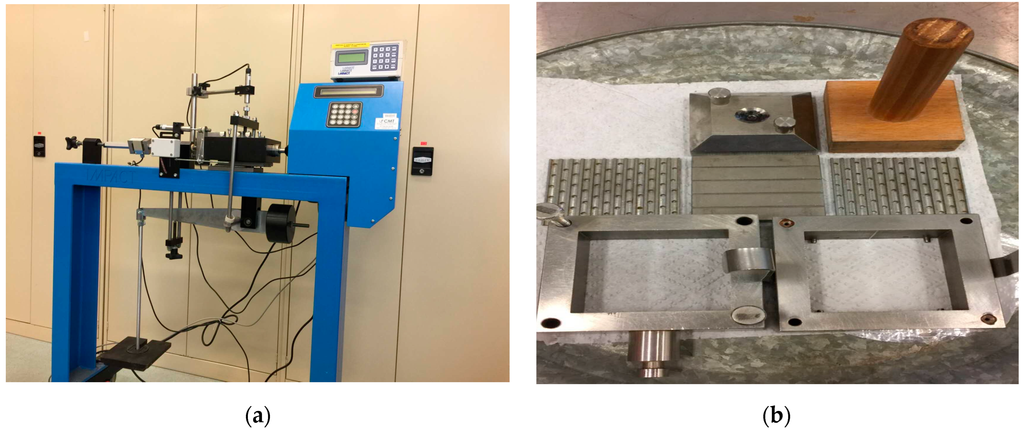
Figure 1. Shear box apparatus: (a) shear box apparatus and data log; (b) 60 mm × 60 mm shear box.
Geotechnics 03 00007 g001
Figure 2. Flume apparatus: (a) location of the pore water pressure sensors (PS1 and PS2) and water content sensors (MS1-MS5); (b) an image of the slope prior to testing.
Geotechnics 03 00007 g002
Figure 3. A typical calibration curve for pore water pressure and suction.
Geotechnics 03 00007 g003
Figure 4. Time series data of pore water pressure (a,c,e) and water content (b,d,f). The following values rainfall intensity were used: 100 mm/hour (a,b), 70 mm/hour (c,d), and 40 mm/hour (e,f).
Geotechnics 03 00007 g004
Figure 5. Slope failure patterns associated with different rainfall intensities: 100 mm/h (a,b,c), 70 mm/h (d,e,f,g) and 40 mm/h (h,i,j,k). Explanation is provided in the text.
Geotechnics 03 00007 g005
Figure 6. Typical examples of the progressive slope failure observed in the flume experiments with rainfall intensities of 70 mm/h (a,b) and 100 mm/h (c).
Geotechnics 03 00007 g006
Figure 7. Forces acting on soil mass in an infinite slope. N is the normal force, W is the weight of the soil mass, S is the shear strength of soil along the failure plane, H is the height of the slope, β is the slope angle, L is the width of a slice, and mH is the thickness of the saturated layer.
Geotechnics 03 00007 g007
Figure 8. Results of the numerical analysis plotted as time series data of the factor of safety obtained for different rainfall intensities and the initial moisture content.
Geotechnics 03 00007 g008
Table 1. Shear box test results.
Moisture Content (%)Apparent Cohesion (kPa)Friction Angle (°)
22739
121839
171434
31034
Table 2. The input parameters for the numerical model.
NotationHow It Is ObtainedValue
HFlume test0.55
ß*According to Ravindran and Gratchev [7]0.95
nCalculations using lab data0.46
SrCalculations using lab data15
c’Shear box test0
ϕ’Shear box test34
cψEquation (4)
αAccording to Montrasio, Valentino and Losi [22]3.4
λAccording to Montrasio, Valentino and Losi [22]0.4
AEstimation from shear box tests45.2
GLab tests2.63
LConstant factor for converting forces to line loads1
ktLab tests2.00 × 10−5
c*ψEquation (4)6.43
nwEquation (10)0.39
ΩEquation (11)0.41
ГEquation (7)1.48
Table 3. Comparison of the time of slope failure from the flume test and numerical analysis.
Test No.123456
Rainfall intensity (mm/h)40407070100100
Initial moisture content (%)510510510
Time to failure (min) from flume testsNo failureNo failure2101809085
Time to failure (min) predicted by the numerical modelNo failureNo failure14512210286
Disclaimer/Publisher’s Note: The statements, opinions and data contained in all publications are solely those of the individual author(s) and contributor(s) and not of MDPI and/or the editor(s). MDPI and/or the editor(s) disclaim responsibility for any injury to people or property resulting from any ideas, methods, instructions or products referred to in the content.