Article

Analysis of the Mobilization of an Unsaturated Infinite Natural Slope Due to Strength Reduction

1
Geoenvironmental Group, Universidad de Castilla-La Mancha, Avda. Camilo José Cela s/n, 13071 Ciudad Real, Spain
2
Department of Civil and Environmental Engineering, Universitat Politècnica de Catalunya, C. Jordi Girona 1-3, 08034 Barcelona, Spain
*
Author to whom correspondence should be addressed.
Geotechnics 2022, 2(4), 1027-1034; https://doi.org/10.3390/geotechnics2040048
Submission received: 25 October 2022 / Revised: 17 November 2022 / Accepted: 21 November 2022 / Published: 23 November 2022

Abstract

:
This work analyses the mobilization of infinite natural slopes that are initially partially saturated. Starting from dry conditions (the water table is assumed to be deep, far from the slope surface), the soil shear strength will decrease when the wetting front advances from the surface. First, the geometry of the failure mechanism that can develop because of such strength reduction is determined. Second, after the mobilization causes the progressive reduction in the soil strength, the slide speed reached the minimum strength is determined, obtaining an indicator of the risk derived from failure.

1. Introduction

Landslides are an environmental and safety problem of the greatest social importance [1,2,3,4]. However, their characterization and study are not straightforward. This is why, despite its limitations, the hypothesis of infinite slope and planar landslide is a useful tool for their analysis, as in the classic works of Taylor [5] and Skempton and Delory [6], as well as in more recent research by Duncan et al. [7], Ng et al. [8], Dey et al. [9] and Huang et al. [10], among others. Assuming plane strain for an ideally homogeneous soil, the stress field is univocally defined because of the symmetry of the problem when the depth z values are small compared to the length of the slope L in the direction defined in Figure 1a. Thus, it is possible to study slope failure analytically. For this purpose, Limit Equilibrium techniques are usually applied, approximating the failure envelope using a Mohr-Coulomb model (see, for example, the review presented by Zhang et al. [11]). In addition, symmetry also makes it possible to identify the translational failure mechanism (Figure 1a). Chen [12] and Atkinson [13], among others, used this mechanism after applying Limit Analysis techniques to uniquely characterize the slope failure in idealized conditions.
Under natural conditions, hillslopes are usually unsaturated [14]. Many slides occur as a consequence of heavy rain events, which increase the water content of the partially saturated soil and, thus, reduce its shear strength [15,16]. Taking the work of Kim et al. [17] as a reference, the present work analyses this process. To this end, after defining the stress state of the soil and the type of failure mechanism to be considered, this work characterizes of the pore-water pressure profile and the stress state when the failure occurs. Then, applying the Work-Energy Theorem [15], the increase in speed of this sliding mechanism is analyzed when the soil strength parameters are reduced as mobilization advances. This speed is an indicator of the risk derived from system failure. Therefore, the magnitudes that control the risk can be identified by parametrizing the expression for the speed. This parametrization provides a new tool to quantify the landslide risk for an ideally infinite slope.

2. System Analysis and Conceptual Framework Adopted

Figure 1 shows a section of the geometry of the homogeneous natural slope considered. Plane strain is assumed. Since the slope is infinitely long both to the left and to the right of the represented zone, segment L is symmetric with respect to any other segment of the slope.
Symmetry determines the general shape of the failure mechanism. Any mechanism other than the translational block represented in Figure 1a [18] would imply the contact of the slip surface with the slope surface, and symmetry would not be fulfilled. The slip line at depth zF (“F”: failure) is an idealization of the base shear zone (Figure 1b) where the plastic strains of the failure mechanism are concentrated.
Symmetry also allows the stress state of the system to be determined. First, if forces RR and RL in Figure 1b (vector magnitudes are represented in bold throughout the paper) were not equal, a situation would arise in an infinite slope in which either of them would become infinite. Therefore, the resultant force of RR and RL must be zero. In the same way, the normal σ and shear τ stresses on any plane Γ parallel to the slope are homogeneous. Applying equilibrium between the stresses on Γ and the weight W of the mass above Γ.
σ = ρ g z c o s 2 β τ = ρ g z cos β sin β
where ρ is the average soil bulk density, g is the gravitational acceleration, z is the depth of Γ, and β is the slope angle. Consequently, as noted above, symmetry determines the stress state of the soil.
For the considered partially saturated conditions, the definition of effective stress σ′ proposed by Alonso et al. [19] can be adopted
σ = σ + S r s m
where σ is the total stress vector (engineering or Voigt notation is used for both stress and strain tensors), s is the matric suction (identified with the capillary suction: s = PGPL, where PL is the liquid pressure), the gas pressure PG in the system is assumed to equal the atmospheric pressure, taken as reference (Patm = 0), Sr is the effective degree of saturation (freely available water), and m is the vector form of the Kronecker delta. Consistent with Equation (2), among the formulations for extending the Mohr-Coulomb linear failure envelope to partially saturated soils (see, for instance, Fredlund et al. [20]; Sheng [21]; Sheng et al. [22]), the following model is adopted [19]
τ F = c + σ F t a n φ = σ F t a n φ + c + S r s t a n φ
where τF is the failure shear stress, c′ is the cohesion, σF is the total normal stress, σF is the effective normal stress, both in the failure plane, and φ′ is the friction angle.
If low initial water content is assumed (deep water table), the initial suction will be high. Consequently, according to Equation (3), the reduction in suction due to the advance of a wetting front will cause a relevant decrease in shear strength. Therefore, it is a critical situation for the stability of the system and can be understood as the triggering factor that induces mobilization.
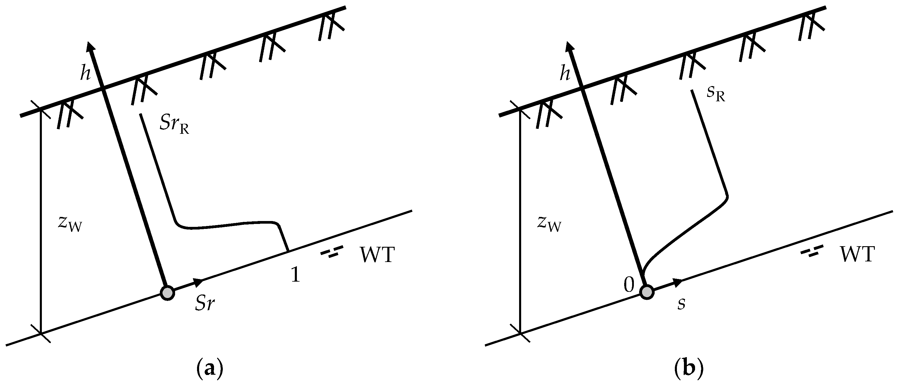
For a position of the water table (WT) deep enough (zW), a degree of saturation profile as shown in Figure 2a is assumed (see, for example, Terzaghi [23]), with an associated matric suction profile as that of Figure 2b. The residual degree of saturation SrR corresponds to suction sR, which is linked to the soil field capacity.
A wetting process propagating from the surface as a consequence of a rainfall event is analyzed. Although the modeling of such a process using a wetting front is a non-negligible simplification (see, for instance, Zhang et al. [11]; Huang et al. [10]), it is a useful modeling strategy. The present study assumes that the progress of the wetting front causes the matric suction profile to evolve with time t as outlined in Figure 3 (adapted from [11]). The soil area closer to the surface is considered to be saturated, in a “perched saturation,” as referred to by Hungr et al. [15], in which the matric suction is zero. Deeper into the soil, matric suction is assumed to reach a value of sR after a transition band. The shape of this transition band, and that of the transition from sR to 0 close to the initial position of the water table, depends on the type of soil. However, this is not relevant for the calculations in the following section, which are only conditioned by the fact that suction is null in the perched saturation zone.

3. Failure and Mobilization

According to Equation (1), the shear stress at the base of the failure mechanism can be calculated as
τ F = ρ g z F cos β sin β
Moreover, according to Equation (3), it will also follow that
τ F = ρ g z F c o s 2 β tan φ 0 + c 0 + S r s tan φ 0
For mobilization to occur, the resistance must be less than in the stable state. The decrease is due to the loss of strength caused by saturation, as the suction s becomes zero, rewriting Equation (5) as
τ F = ρ g z F c o s 2 β tan φ 0 + c 0
where zF is given by the expression
z F = c 0 ρ g cos φ 0 cos β sin ( β - φ 0 )
As noted by Potts et al. [24] and Chen et al. [25], if the mobilization δu progresses, the strains at the base shear zone will increase, and the soil strength will be reduced. Disregarding viscous terms such as those indicated by Iverson [26] and, for simplicity, adopting a linear model, the evolution of φ′ and c′ shown in Figure 4a can be assumed. When φ′ is equal to φ0 (initial saturated situation), integrating the value of τ at zF, τF0 in Figure 4b, leads to a stabilizing load T that balances the tangential component of the weight WT. According to Equations (1) and (3)
τ F 0 = c 0 + σ F tan φ 0 = c 0 + ρ g z F c o s 2 β tan φ 0
However, when δu increases, φ′, and c′ decrease [24], and τF will be lower (Figure 4b)
τ F = c + ρ g z F c o s 2 β tan φ
Consequently, T will not balance WT, resulting in the accelerated sliding of the mechanism at zF. The decrease in friction angle and cohesion accelerates the mechanism, increasing its kinetic energy as the mobilization progresses. According to the Work-Energy Theorem [15,27], when a slope segment reaches displacement δu, the failure mechanism will have kinetic energy EC
E C = 1 2 M v 2 = 0 δ u ( W T T ) δ u
where M is the mass of the segment, WT and T are the moduli of vectors WT and T, respectively, and v is the speed of displacement. T is equal to the product of τF and the contact area A at the base shear zone. Therefore, the previous Equation (10) can be written as
1 2 M v 2 = A 0 δ u ( τ F 0 τ F ) δ u
And the kinetic energy per unit of mobilized volume eC, taking into account Figure 4b, can be expressed as
e C = 1 2 ρ v 2 = 1 z F cos β τ F 0 τ F 1 2 δ u 1
Introducing Equations (7)–(9), the coefficient FRI can be defined as
F R I = v 2 g δ u 1 = [ tan φ 0 tan φ 1 tan β + ( 1 tan φ 0 tan β ) ( 1 c 1 c 0 ) ] sin β

4. Discussion

As the mobilization progresses, Equation (12) indicates that the kinetic energy of the system associated with δu1 is proportional to the shaded area in Figure 4b. The mechanical energy stored in the base shear zone transforms into kinetic energy as the mobilization progresses and τF decreases. The tendency to gain kinetic energy is defined by Equation (13), in which the dimensionless term (v2/g)/δu1 can be understood as the relation between the kinetic energy per unit mass that is reached in δu1 (when all the reduction in soil strength has taken place) and displacement δu1 after the mechanical energy of the shaded area has been dissipated. Therefore, the efficiency of the system to gain kinetic energy as the strength decreases can be understood as a failure risk index FRI.
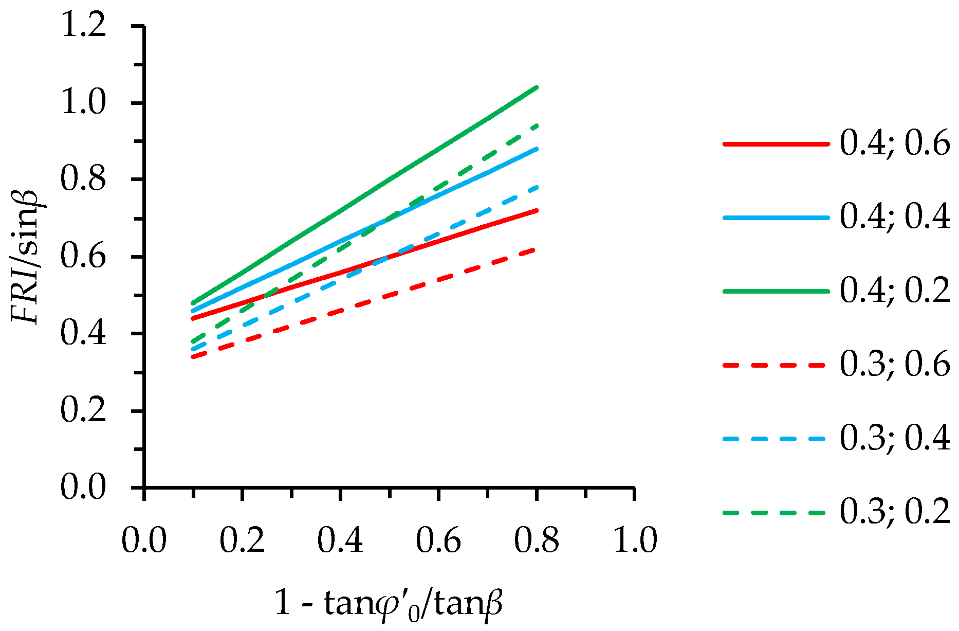
For any given slope, the higher β with respect to φ0 (increasing 1—tanφ0/tanβ in the horizontal axis in Figure 5), the greater the tendency to gain kinetic energy, increasing FRI. FRI also increases with decreasing c1 with respect to c0 (second number in the legend, c1/c0, Figure 5). Furthermore, the greater the difference between φ0 and φ1 (represented by the first number in the legend, (tanφ0—tanφ1)/tanβ, Figure 5), the more kinetic energy is gained. As expected, the higher the slope angle and the lower the final strength, the greater the kinetic energy gained for the same initial strength φ0.
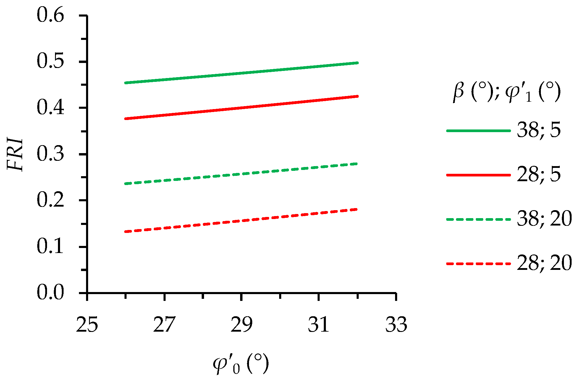
It is not so straightforward to predict the effect of different φ0 values on the energy when the soil reaches its final strength. Figure 6 compares the FRI values as a function of φ0 obtained with β of 38° and 28° and φ1 of 5° and 20° while taking c1 as the 40% of c0. As expected, fixing φ1, FRI increases with increasing β for any φ0. Moreover, fixing β, FRI increases with decreasing φ1. However, for any given β and φ1 values, FRI increases with φ0: the higher the soil strength before failure, the greater the kinetic energy of the soil after reaching its ultimate strength. As noted above, the soil dissipates the stored mechanical energy (shaded area in Figure 4b) when reaching its ultimate strength. The higher the soil strength before initiating the failure mechanism, the larger the shaded area. Therefore, the base shear zone will have more energy stored, and the kinetic energy gained when reaching the ultimate strength will be greater.
It should be noted that as Equation (7) indicates, assuming a certain cohesion and bulk density, the greater φ0, the greater zF. This is shown in Figure 7, in which the dimensionless depth of the failure ρgzF/c0 is represented. As noted above, for mobilization to begin, the wetting front must reach zF. For a given initial water content profile, the probability that the wetting front reaches a certain depth is related to the probability of a rainfall event of enough duration for it to occur. For a greater zF value, such a rainfall event is less likely. Therefore, it may be questionable to compare the value of FRI for different values of φ0 (Figure 6) since it involves comparing processes of different probabilities P of occurrence. The comparison would be more consistent if this probability were introduced in the calculation of FRI, analyzing, for instance, the value of P(FRI). However, such an analysis is beyond the scope of this paper. This study aims to analyze not the damage that a landslide could cause, characterized by P(FRI), but rather how vulnerable a slope is to the mobilization derived from a decrease in φ′. Then, FRI can be considered a good indicator of this vulnerability.

5. Conclusions

The analysis of the mobilization of a partially saturated infinite slope was presented. Initial dry conditions were assumed, and a Mohr-Coulomb failure model was adopted. Based on the symmetry of the slope, the stress state of the translational block that defines the analyzed failure mechanism was derived. The application of the Work-Energy Theorem made it possible to obtain an estimate of the speed of the block when the soil strength capacity is reduced to its ultimate value. A failure risk index was defined from the expression of that speed. In addition, an energy analysis was carried out, which illustrates an aspect of practical interest: the kinetic energy of the sliding system is greater for more resistant soils when that ultimate strength is reached.

Author Contributions

Conceptualization, V.N. and E.R.; methodology, V.N. and G.D.l.M.; software, V.N. and G.D.l.M.; validation, V.N., G.D.l.M., E.R. and L.A.; formal analysis, G.D.l.M., E.R. and J.T.-S.; investigation, E.R.; resources, V.N.; data curation, G.D.l.M.; writing—original draft preparation, V.N.; writing—review and editing, V.N., J.T.-S. and L.A.; visualization, G.D.l.M., E.R. and J.T.-S.; supervision, V.N.; project administration, L.A. All authors have read and agreed to the published version of the manuscript.

Funding

This research received no external funding.

Data Availability Statement

Restrictions apply to the availability of the data. Data were obtained from the references cited throughout the text and are available from those documents.

Acknowledgments

This work was supported by a ‘Margarita Salas’ grant from Ministerio de Universidades—Gobierno de España, awarded to Joel Torres-Serra.

Conflicts of Interest

The authors declare no conflict of interest.

References

  1. Lacasse, S.; Nadim, F.; Kalsnes, B. Living with Landslide Risk. Geotech. Eng. J. SEAGS AGSSEA 2010, 41, 4. [Google Scholar]
  2. Shanmugam, G.; Wang, Y. The Landslide Problem. J. Palaeogeogr. 2015, 4, 109–166. [Google Scholar] [CrossRef] [Green Version]
  3. Gariano, S.L.; Guzzetti, F. Landslides in a Changing Climate. Earth Sci. Rev. 2016, 162, 227–252. [Google Scholar] [CrossRef] [Green Version]
  4. Puzrin, A.M. Editorial: Modern Trends in Landslide Mechanics. Géotechnique 2016, 66, 173–174. [Google Scholar] [CrossRef] [Green Version]
  5. Taylor, D.W. Fundamentals of Soil Mechanics; John Willey & Sons: New York, NY, USA, 1948. [Google Scholar]
  6. Skempton, A.W.; Delory, F.A. Stability of Natural Slopes in London Clay. In Proceedings of the 4th International Conference on Soil Mechanics and Foundation Engineering; Butterworths Scientific Publications: London, UK, 1957; pp. 378–381. [Google Scholar]
  7. Duncan, J.M.; Wright, S.G.; Brandon, T.L. Soil Strength and Slope Stability; John Willey & Sons: Hoboken, NJ, USA, 2014. [Google Scholar]
  8. Ng, C.W.W.; Liu, H.W.; Feng, S. Analytical Solutions for Calculating Pore-Water Pressure in an Infinite Unsaturated Slope with Different Root Architectures. Can. Geotech. J. 2015, 52, 1981–1992. [Google Scholar] [CrossRef]
  9. Dey, R.; Hawlader, B.; Phillips, R.; Soga, K. Modeling of Large-Deformation Behaviour of Marine Sensitive Clays and Its Application to Submarine Slope Stability Analysis. Can. Geotech. J. 2016, 53, 1138–1155. [Google Scholar] [CrossRef] [Green Version]
  10. Huang, W.; Leong, E.-C.; Rahardjo, H. Upper-Bound Limit Analysis of Unsaturated Soil Slopes under Rainfall. J. Geotech. Geoenvironmental Eng. 2018, 144, 04018066. [Google Scholar] [CrossRef]
  11. Zhang, L.L.; Zhang, J.; Zhang, L.M.; Tang, W.H. Stability Analysis of Rainfall-Induced Slope Failure: A Review. Proc. Inst. Civ. Eng.-Geotech. Eng. 2011, 164, 299–316. [Google Scholar] [CrossRef] [Green Version]
  12. Chen, W.-F. Limit Analysis and Soil Plasticity; Elsevier Science: Amsterdam, The Netherlands, 1975. [Google Scholar]
  13. Atkinson, J. The Mechanics of Soils and Foundations; Taylor & Francis: New York, NY, USA, 2007. [Google Scholar]
  14. Lim, T.T.; Rahardjo, H.; Chang, M.F.; Fredlund, D.G. Effect of Rainfall on Matric Suctions in a Residual Soil Slope. Can. Geotech. J. 1996, 33, 618–628. [Google Scholar] [CrossRef]
  15. Hungr, O.; Corominas, J.; Eberhardt, E. Estimating Landslide Motion Mechanism, Travel Distance and Velocity. In Landslide Risk Management; Hungr, O., Fell, R., Couture, R., Eberhardt, E., Eds.; Taylor & Francis Group: London, UK, 2005; pp. 99–128. [Google Scholar]
  16. Rahardjo, H.; Lee, T.T.; Leong, E.C.; Rezaur, R.B. Response of a Residual Soil Slope to Rainfall. Can. Geotech. J. 2005, 42, 340–351. [Google Scholar] [CrossRef]
  17. Kim, J.; Salgado, R.; Lee, J. Stability Analysis of Complex Soil Slopes Using Limit Analysis. J. Geotech. Geoenvironmental Eng. 2002, 128, 546–557. [Google Scholar] [CrossRef]
  18. Iverson, R.M. Regulation of Landslide Motion by Dilatancy and Pore Pressure Feedback. J. Geophys. Res. 2005, 110, F02015. [Google Scholar] [CrossRef]
  19. Alonso, E.E.; Pereira, J.-M.; Vaunat, J.; Olivella, S. A Microstructurally Based Effective Stress for Unsaturated Soils. Géotechnique 2010, 60, 913–925. [Google Scholar] [CrossRef] [Green Version]
  20. Fredlund, D.G.; Morgenstern, N.R.; Widger, R.A. The Shear Strength of Unsaturated Soils. Can. Geotech. J. 1978, 15, 313–321. [Google Scholar] [CrossRef]
  21. Sheng, D. Review of Fundamental Principles in Modelling Unsaturated Soil Behaviour. Comput. Geotech. 2011, 38, 757–776. [Google Scholar] [CrossRef]
  22. Sheng, D.; Zhou, A.; Fredlund, D.G. Shear Strength Criteria for Unsaturated Soils. Geotech. Geol. Eng. 2011, 29, 145–159. [Google Scholar] [CrossRef]
  23. Terzaghi, K. Theoretical Soil Mechanics; John Wiley & Sons, Inc.: Hoboken, NJ, USA, 1943. [Google Scholar]
  24. Potts, D.M.; Dounias, G.T.; Vaughan, P.R. Finite Element Analysis of Progressive Failure of Carsington Embankment. Géotechnique 1990, 40, 79–101. [Google Scholar] [CrossRef]
  25. Chen, X.; Zhu, H.; Huang, J.; Liu, D. Stability Analysis of an Ancient Landslide Considering Shear Strength Reduction Behavior of Slip Zone Soil. Landslides 2016, 13, 173–181. [Google Scholar] [CrossRef]
  26. Iverson, R.M. Comment on “The Reduction of Friction in Long-Runout Landslides as an Emergent Phenomenon” by Brandon C. Johnson et Al. J. Geophys Res. Earth Surf. 2016, 121, 2238–2242. [Google Scholar] [CrossRef]
  27. Hungr, O. Dynamics of Rapid Landslides. In Progress in Landslide Science; Springer: Berlin/Heidelberg, Germany, 2007; pp. 47–57. [Google Scholar]
Figure 1. Section of the geometry of the unsaturated infinite natural slope considered. (a) Translational block of the failure mechanism; (b) Static equilibrium diagram.
Geotechnics 02 00048 g001
Figure 2. (a) Initial degree of saturation Sr profile; (b) Initial matric suction s profile, where h is the hydraulic head when the water table is located at a depth zW.
Geotechnics 02 00048 g002
Figure 3. Evolution with time t of the matric suction caused by the advance of a wetting front (t2 > t1).
Geotechnics 02 00048 g003
Figure 4. (a) Friction angle φ′ and cohesion c′ as a function of mobilization displacement δu; (b) Shear strength τF as a function of mobilization displacement δu.
Geotechnics 02 00048 g004
Figure 5. FRI/sinβ as a function of (1−tanφ0/tanβ) for values of the term (tanφ0−tanφ1)/tanβ of 0.4 and 0.3 (the first number in the legend) and for values of term c1/c0 of 0.2, 0.4 and 0.6 (the second number in the legend).
Geotechnics 02 00048 g005
Figure 6. FRI as a function of φ0 for slope angles β and φ1, taking c1/c0 = 0.4.
Geotechnics 02 00048 g006
Figure 7. The dimensionless depth of the slip surface ρgzF/c0 as a function of the soil friction angle φ0 and the slope angle β.
Geotechnics 02 00048 g007
Publisher’s Note: MDPI stays neutral with regard to jurisdictional claims in published maps and institutional affiliations.