Article

Biomechanical Evaluation of a Spinal Surgical Instrument: A Numerical–Experimental Approach

Department of Chemistry, Materials and Chemical Engineering “Giulio Natta”-LaBS, 20133 Politecnico di Milano, Italy
*
Author to whom correspondence should be addressed.
Biomechanics 2025, 5(2), 26; https://doi.org/10.3390/biomechanics5020026
Submission received: 24 February 2025 / Revised: 28 March 2025 / Accepted: 18 April 2025 / Published: 20 April 2025
(This article belongs to the Section Injury Biomechanics and Rehabilitation)

Abstract

:
Background/Objectives: The conventional practice in clinical settings involves using multi-use surgical instrumentation (SI). However, there is a growing trend towards transforming these multi-use SIs into disposable surgical instruments, driven by economic and environmental considerations without considering the biomechanical aspects. This study focuses on redesigning an SI kit for implanting cervical spinal facet cages. Understanding the boundary conditions (forces, torques, and bending moments) acting on the SI during surgery is crucial for optimizing its design and materials. Therefore, this study aims to develop a measurement system (MS) to record these loads during implantation and validate it through in vitro testing. Methods: A combined numerical–experimental approach was used to design and calibrate the MS. Finite element analysis (FE) was used to optimize the geometry of the sensitive element of the MS. This was followed by the manufacturing phase using 3D printing and then by calibration tests to determine the stiffness of the system. Finally, the MS was used to measure the boundary conditions applied during SI use during in vitro tests on a cervical Sawbone spine. Results: After designing the measurement system (MS) via finite element analysis, calibration tests determined stiffness values of KF = 1.2385 N/(µm/m) (axial compression), KT = −0.0015 Nm/(µm/m) (torque), and KB = 0.0242 Nm/(µm/m) (non-axial force). In vitro tests identified maximum loads of 40.84 N (compression) and 0.11 Nm (torque). Conclusions: This study developed a measurement system to assess surgical implant boundary conditions. The data will support finite element modeling, guiding the optimization of implant design and materials.

1. Introduction

In order to design a new medical device, an integrated approach is commonly used, which accounts for computational simulations and experimental tests. This integrated methodology presents significant advantages over traditional design approaches, offering powerful tools for the development of medical devices. Combining the strengths of numerical modeling and experimental validation enhances efficiency, accuracy, and cost-effectiveness throughout the design process. In particular, knowing the stress state in materials is crucial for predicting components’ behavior and potential failures; such stresses can be calculated using the finite element method (FEM), knowing the geometrical and material properties with the advantage of minimizing iterations, thus making the design process faster and more cost-effective [1].
The object of this study is a surgical kit for posterior facet cage implantation on the cervical portion of the spine. In particular, the kit is already available on the market, and it is composed of multi-use surgical instruments (SIs) that can undergo multiple uses across several procedures and that have to be sterilized multiple times before hospital storage to prevent cross-infection among patients. A recent trend suggests transforming multi-use SIs into disposable surgical instruments due to economic and environmental factors; indeed, the lifecycle of reusable SIs involves complex and expensive phases, encompassing production, packaging, transportation, sterilization, and logistical procedures such as registration and documentation. Frequent sterilization, especially with steam, has a significant cost and environmental impact due to water and energy consumption [2,3]. In contrast, disposable SI kits, compactly packaged and sterilized, offer cost-effective solutions, minimizing instrument usage and reducing intra-operative infection risks [4,5,6]. This approach streamlines logistics, lowers costs [7,8,9], and potentially enhances surgical efficiency [10,11,12,13,14,15,16,17].
Redesigning a multi-use system into a single-use system requires a multidisciplinary approach that considers environmental, economic, and mechanical reliability factors.
To the best of the authors’ knowledge, the existing literature primarily focuses on environmental and economic considerations while completely overlooking the mechanical aspects. Hence, the need arises for a redesign in terms of material and geometry to transition the current multi-use SI to a single-use SI. The benefits associated with using computational models for mechanical design [1] require reliable models with boundary conditions that are as realistic as possible. Understanding these boundary conditions in terms of forces, torque, and bending moments is crucial for accurately assessing the performance of the modified instrument.
In order to identify the boundary conditions applied by the surgeon during surgery, it is essential to have a measurement system (MS) that can be paired with different SIs to record the force, torque and bending moment.
Therefore, the aim of this work is to develop an MS capable of recording the loads applied by the surgeon during cage implantation.
To achieve this goal, the development of the MS involves several steps: (i) performing finite element simulations to determine the appropriate dimensions of the MS; (ii) 3D printing and calibrating the MS through ad hoc testing; and (iii) performing a comprehensive validation of the MS through testing under conditions that mimic in vivo implantation.

2. Materials and Methods

This study employed a spinal SI as the subject of investigation, specifically designed for the implantation of a cervical facet cage (Sharkage by 2B1 s.r.l., Milan, Italy and Leghe Leggere Lavorate s.r.l., Milan, Italy). The manufacturer provided all the necessary CAD files and the different stainless-steel samples of the multi-use surgical kit for the experimental activity.
The Sharkage SI comprises three stainless-steel instruments (namely a chisel, forks, and a reamer) designed to sequentially prepare the operative site for cage placement; each of these instruments reach the posterior facets and force them to open and host the cage. The progression of these SIs is facilitated by utilizing a Beat Plug (BP), which serves as a handle.
Experimental photographic evidence, as reported in Figure 1, obtained using a Canon EOS 6D digital camera (Ota, Tokyo, Japan) (20.2 MP) with various magnification modes (2× to 5×), was obtained from a Sharkage instrument kit (2B1 s.r.l., Milan, Italy) utilized approximately 10 times; after usage of the forks component, notable permanent deformations appeared. These deformations pose a risk of compromising the optimal functionality of the surgical instrument and may lead to fracture during the surgical procedure, as reported above.

2.1. Development of an ad hoc Measurement System (MS)

In order to measure the boundary condition during the surgical operation, an ad hoc MS was developed.
Each step of the surgical technique, as described in the surgical kit instructions, was meticulously analyzed in collaboration with the surgeon. This analysis involved a detailed evaluation of the individual movements performed during the procedure in order to accurately characterize the mechanical interactions between the instruments and the surgical environment. As a result, two primary loading conditions acting on the instruments were identified: axial compression and torque. In addition, the potential presence of a bending moment was considered, as its influence may vary depending on the specific surgical maneuver. These loads were found to be the predominant mechanical factors affecting the performance of SIs during implantation.
The design requirements for the MS, considering that it will be manufactured using reverse stereolithography 3D printing, are as follows: (i) the system must be able to measure the compressive forces, torques, and bending moments to which the instrument is subjected; (ii) the system dimensions must allow for sufficient sensitivity in reading the applied loads; (iii) the material for the MS production must ensure proper MS functionality during use; and (iv) the MS manufacturing must be performed cost-effectively.
In adherence to the aforementioned requirements, the MS is composed of different parts (Figure 2b): (a) the sensitive element, which will be instrumented with strain gauges (SGs) to record the deformations that occur during the different loading conditions; (b) the connector, which is the final part of the sensitive element compatible with the SI (in particular, the MS must avoid the reciprocal translation and rotation between itself and the SI to enable the recording of the force and the torque); and (c) the cover and the cap needed to protect the sensor and to allow for the electrical connection between the SGs and the amplifier system (Figure 2b).
By adhering to these mechanical design requirements, the measurement system for the Beat Plug instrument was systematically developed.
Numerical methods were used to (i) dimension the component under a safety factor, (ii) maximize the component’s sensitivity, and (iii) facilitate the identification of the optimal position of the SG within the final component to have good measurement precision.
Iterative simulations were performed to identify the best designs that adhere to the specific fundamental design requisites reported in Section 3.1.
The 3D geometry was designed using Solidworks 2023 (Dassault Systemes, SIMULIA Corp., Johnston, RI, USA). Each 3D geometry was discretized with 17′944 C3D8 elements with an element size equal to 0.5 mm, in correspondence with a cylindrical sensitive part (Figure 2c), and 652′918 C3D10 elements with an element size equal to 0.5 mm in the remaining part. A mesh sensitivity analysis was performed, with particular care given to the sensitive element of the system, which corresponded to a square of 3 × 3 mm, comparable to the SG’s dimension. The quantities of interest that were monitored until convergence (percentage variation < 5%) were the average von Mises stress (σVM), the average deformations in correspondence to the square zone cited below, and the stiffness of the system, calculated as the force divided by the displacement. All models described herein were built and run in the Abaqus 2022 environment (Dassault Systemes, SIMULIA Corp., USA).
Three different simulations were performed (Figure 3a,b) as follows: (i) by applying a pure vertical compressive force of 100 N to the upper surface using a continuum-distributed coupling interaction while imposing an encastre boundary condition at the insertion point of the forks instrument; (ii) by applying a pure torque of 1.5 Nm on the superior face; and (iii) by applying a vertical non-axial force equal to 100 N, with a 20 mm lever arm, to generate both a compression force and bending on the structure.
The material of the MS was modeled with a Young’s modulus and Poisson’s modulus equal to 2.8 GPa and 0.4 to match the properties of the commercial resin material (grey resin, Formlabs, Somerville, MA, USA) that will be used for the 3D printing of the instrument with reverse stereolithography.
The von Mises stresses and principal deformations were calculated and analyzed in order to choose the correct dimensions of the instrument so that yield was avoided (65 MPa-Grey resin, Formlabs, Somerville, MA, USA) and to obtain the direction of the principal strain, which is useful in positioning and orientating the SGs on the sensitive element. At the same time, the FEM enabled the assessment of the strain amplitudes at the corresponding positions of the SGs to ascertain whether the amplitudes were sufficiently high to be detected by the SGs.
The final design was 3D-printed using reverse stereolithography Form 3B (Formlabs Inc., Somerville, MA, USA) in resin material with a layer thickness of 0.05 mm.
Four SG rosettes (N32-FA-1-120-11-VS3, Showa Measuring Instruments Co., Ltd., 1-17-16 Nishihokima, Adachi-ku, Tokyo, Japan) were bonded to the sensitive element, as shown in Figure 4a,b (A, B, C, and D), according to the finite element analysis carried out in Section 3.1.
The 0° grid was aligned with the longitudinal cylinder axis (Figure 4a), and the axial deformation was calculated according to Equation (1), where ε A , ε B , ε C , and ε D are the deformations of each SG on the MS:
ε A V G = ε A + ε B + ε C + ε D 4
For recording the torsion only on the MS, the inclined grids (45° and −45°) of two opposite SG rosettes were used (specifically, the SG A and C rosettes, as reported in Figure 4a). Compensation for the thermal effect in the SG rosettes was achieved by using a half-bridge Wheatstone configuration with a dummy specimen (Figure 5b). Due to the symmetry of the MS and the SG position, the bending moment could be also obtained. The SG rosettes were connected to an MX840B (HBM, Darmstadt, Germany) amplifier system (Figure 5b).

2.2. Calibration of the MS: Experimental Tests

Since forces and torques are unknown during surgery, a calibration of the MS was needed in order to obtain the forces and torques from the deformation measurements performed by the SG. In particular, the following three different loading conditions were analyzed (Table 1): (i) the pure axial compression force (case C) (Figure 6a); (ii) the pure torsion (case T) (Figure 6b); and (iii) the non-axial force resulting in a bending moment (case B) (Figure 6c). For each configuration, an ad hoc setup was designed and 3D-printed using Form 3B 3D printer. The experiments were performed under displacement control using an MTS 858 MiniBionix testing machine (MTS System Inc., Minneapolis, MN, USA). The experimental protocols are reported in Table 1.
Three different tests were performed for each configuration to assess the replicability of the procedure. For the three tests, the following six different outputs were recorded: four measurements of the axial deformation (0 grid), combined using Equation (1), and two measurements of the torsional deformation (only from the A and B rosettes).
To draw the calibration curves for the MS, the stiffness was calculated for each experimental test by quantifying the ratio of the applied force (KC), torque (KT), and bending moment (KB) to the resultant deformation. The analysis was conducted specifically on the data obtained during the final cycle of each experiment.
A customized algorithm was devised using Matlab (MathWorks Inc., 2022b, Natick, MA, USA) to automate the postprocessing of the results; in particular, the code was capable of computing the force and torque over time, identifying when the maximum values occurred. Regarding the bending moment, the code discerned the direction of the moment (Figure 5e,h), with a color legend indicating the maximum values for each bending moment (MAB, MBA, MCD, and MDC).

2.3. Experimental Test to Verify the MS’s Suitability

To assess the suitability of the MS in terms of performing measurements in an in-vivo-like condition, in vitro tests were performed to simulate implant conditions in an operating room. A Sawbone (Sawbones, Washington, WA, USA) cervical spine (C0–C7) sample was used and positioned according to the surgical technique. In particular, as reported in Figure 5a,b, the upper and bottom parts of the spine were fixed, and the structure was inclined to replicate the flexion of the cervical section of the patient’s spine during surgery. In order to account for inter-operator variability, three different operators performed the experiments, mimicking cage implantation using the MS coupled with the chisel, forks, and reamer instruments. In particular, a bilateral implantation was simulated, starting from the right (R) and then moving to the left (L) side from the C2 to C7 levels according to the surgical technique (Figure 5d). The postprocessing code was used after each test to visualize the entire loading history (Figure 5f–h) and find the maximum value of the force (compression force), torque, and bending moments, distinguishing them based on their directions (Figure 5e). The inter-operators’ average and standard deviation were calculated for each implanting position (R and L) and level (from C2 to C7).

3. Results

3.1. Development of an ad hoc Measurement System (MS)

The sensitive element of the MS was dimensioned using the numerical simulations (obtaining a 20 mm diameter and 2.5 mm wall thickness) so that yielding is prevented and that the sensitivity is sufficient even for small applied forces and torques. The results from the numerical simulation show that a 10 N pure compression force induced a 20 μm/m strain on the sensitive element, which is within the sensitivity range for the SG.
Under all three loading conditions, the sensitive element did not reach yielding (see Figure 3c); the value of the loads that result in yielding for each configuration are 2000 N for the pure compression force, 9.3 Nm for the pure torque, and 300 N for the non-axial force, with the lever arm equal to 20 mm, which seem to be far beyond any imaginable value achievable during surgery.
As reported in Figure 3d, the principal deformation orientations of the sensitive element were analyzed using numerical simulations. Specifically, it can be seen that in the pure compression conditions, the maximum and minimal principal deformations were aligned axially with the applied load, whereas in the pure torsional load, they had an inclination of 45° and −45° with respect to the vertical axis of the MS.
The CAD of the position of the SG rosettes and the sensitive element with the SG glued are reported in Figure 4; the SG rosettes were positioned according to the simulation results cited in the previous paragraph.

3.2. Calibration of the MS: Experimental Tests

The deformations of each SG rosette for the three different calibration tests are shown in Figure 6a–c. The stiffness of the calibration curves was KC = 1.2385 N/(µm/m) for the pure axial compression, KT = −0.0015 Nm/(µm/m) for the pure torque, and KB = 0.0242 Nm/(µm/m) for the non-axial force tests.

3.3. Experimental Test to Verify the MS’s Suitability

The results of the experimental tests are reported in Figure 7a–c for the chisel, forks, and reamer SIs, respectively. For the purpose of conciseness, only the findings concerning the axial force and torsion are presented.
An example of the signals measured during the insertion of the forks and elaborated after postprocessing is reported in Figure 5f–h; in particular the loading history of the axial force, torque, and bending moment for the R and L insertions at the C2–C3 level are reported.

4. Discussion

According to the literature, single-use SIs exhibit varied benefits with respect to both economic and environmental aspects compared to multi-use SIs [2,4,5,7,10,14,15]. To the best of the authors’ knowledge, this is the first study centered on aspects regarding the redesign of SIs from a mechanical standpoint. Understanding the boundary conditions of the SI throughout the procedural phases constitutes an essential prerequisite for geometric and material enhancements, thereby fostering advantageous outcomes across economic and environmental aspects.
To determine the boundary conditions, this study developed an MS to assess the forces, torques, and bending moments during clinical procedures. The process involved several key steps. First, iterative finite element simulations guided the design of the measurement system, which was then 3D-printed and instrumented with SGs. Next, the system was calibrated through experimental testing before being used in an in vitro test on a Sawbone cervical spine specimen.
The conditions were set to identify the dimensions (cylinder diameter, wall thickness, and hole size to enhance the element’s deformability) of the sensitive element (Figure 2b) such that it measured the appreciable deformation values by the SGs even at low forces (10 N). The experiments confirmed the value of the strain obtained from the FEM at 10 N (18 μm/m vs. 20 μm/m, respectively).
Using FEM simulations, the positions of the SGs were selected. The position of the SGs allows for distinguishing the different loading conditions, for example, those caused by a non-centered force on the MS that induces a bending condition (compression force + transport moment). In particular, using Equation (1), the MS was able to distinguish the only component of the compressive force translated to the center of the structure and the pure moment separately. This was also confirmed by calibration tests, where in the two different tests of pure compression and bending (case F and B in Table 1), the average of the SG strain A, B, C, and D values were comparable (81.83 μm/m vs. 83.60 μm/m in compression) when the same vertical force of 100 N was applied. This indicates that in the non-axial compression test with bending, the MS was able to isolate the only vertical component; moreover, during the same tests, the εT_AVG values were negligible (as expected) compared to the pure torsion test, where the εT_AVG deformation reached −924.09 ± 1.75 μm/m and 1003.52 ± 12.22 μm/m (during loading and unloading, respectively). In addition, the configuration enabled the correct identification of the amplitude and the direction of the acting bending moments being different from the transport ones (Figure 5e,h). The measured torque values showed bi-directionality, with positive or negative values depending on the direction of rotation (with a positive value indicating clockwise rotation). However, directionality was not taken into account, as the primary objective was to identify the worst-case scenario, corresponding to the maximum torque value, regardless of the direction.
As regards the cage insertion tests (Figure 7), the average force of the first insertion (R) among the levels was lower with respect to the second insertion (L):, with values of13.63 N vs. 14.88 N for the chisel SI and 35.15 N vs. 35.52 N for the reamer SI, while this trend was not clear for the forks SI (14.78 N vs. 13.50 N). In general, the higher value of the boundary conditions was reached with the reamer SI; this was expected, as the reamer SI effectively scratches and prepares the in situ site for the facet cage insertion (with a maximum value of 40.84 N compared to 35.56 N and 21.32 N for the forks and chisel SI). The loads measured through in vitro tests confirm the appropriateness of the selected loads used in the FEM for the sizing of the sensitive element.
To the best of the authors’ knowledge, this work is the first to investigate and record the boundary conditions applied by the surgeon during spinal device implantation. Understanding these boundary conditions is crucial, as they directly influence the success of the procedure and the mechanical stability of the implant. Furthermore, the ultimate goal of this study was to redesign the surgical instrument, taking into account the boundary conditions it will be subjected to during use.
In contrast, all previous studies focusing on in vivo measurements have been limited to recording forces directly on the implanted device itself (such as rods, screws, and cages) [18,19,20,21]. These studies primarily aim to assess the reaction forces exerted on the implant during different physiological activities, such as standing, walking, or lifting loads. However, they do not provide insight into the forces and moments applied by the surgeon during the implantation process, which play a crucial role in ensuring correct positioning and optimizing the surgical approach.
Certain limitations of the study warrant attention. In particular, (i) the comparison between the FEM results and the experimental measurements may have been affected by the boundary conditions employed in the FEM (which entailed encastre support at the bottom portion and the load applied at the top), while in the in vitro setting and during the practical employment of the MS, the connection between the SI and the MS did not exhibit perfect immobilization, leading to micromotion. Consequently, the outcomes derived from the FEM may have exhibited an overestimation compared with the experimental measurements (about 10%), but this problem is not relevant because the MS was subsequently subjected to calibration; and (ii) during the verification test on the Sawbone cervical spine sample, the boundary conditions were really similar to the in vivo application, but the test was simplified compared to the surgery due to the absence of soft tissue, which could hinder and complicate the procedure, and it may indeed have led to an increment in the measured load values. To address this oversimplification, cadaver testing will be conducted in the future to refine the value of the boundary conditions.

5. Conclusions

This study highlights the design path followed for the development of an MS able to measure the boundary conditions applied to an SI during surgery; by integrating numerical simulations and experimental tests, it was possible to obtain a reliable tool that can be used in future studies. This is a fundamental step in redesigning the SI in terms of the material and its design; specifically, the boundary conditions obtained from cadaver testing will be used in an FEM of the cervical spine, facilitating a comparative analysis of various SI designs in terms of the stress and strain distribution across the SI and the cervical column, thereby guiding optimal design selection.

Author Contributions

Conceptualization, L.C. and T.V.; methodology, L.C.; validation, L.C.; formal analysis, L.C. and T.V.; investigation, L.C.; resources, L.C. and T.V.; data curation, L.C.; writing—original draft preparation, L.C.; writing—review and editing, L.C. and T.V.; visualization, L.C.; supervision, T.V.; project administration, T.V. All authors have read and agreed to the published version of the manuscript.

Funding

This research work was partially funded by the “PON 2014-2020-GREEN Research Field: “Dottorati di ricerca su tematiche green e innovazione: nuove risorse dal PON Ricerca e Innovazione 14-20”, n° 1061 del 18 August 2021” program, Italian Ministry of University and Research.

Institutional Review Board Statement

Not applicable.

Informed Consent Statement

Not applicable.

Data Availability Statement

The original contributions presented in this study are included in this article.

Acknowledgments

The authors acknowledge D. Ninarello and L. Carpenedo for their willingness to have been operators 2 and 3, respectively, in the various experimental tests and A. Belluzzo and A. Grassi for their support in preparing the CAD of the MS and for the optical analysis, respectively. The authors gratefully acknowledge C. Miglietta (2B1 s.r.l., Milan, Italy) and D. Pizzamiglio (Leghe Leggere Lavorate s.r.l., Milan, Italy) for providing the CAD and samples of the spinal SI useful for the numerical and experimental activity.

Conflicts of Interest

The authors declare no conflicts of interest.

Abbreviations

The following abbreviations are used in this manuscript:
SISurgical instrument
MSMeasurement system
SGsStrain gauges
FEMFinite element model

References

  1. Mollica, F.; Ambrosio, L. The finite element method for the design of biomedical devices. Biomater. Hand Surg. 2009, 31–45. [Google Scholar] [CrossRef]
  2. McGain, F.; Moore, G.; Black, J. Hospital steam sterilizer usage: Could we switch off to save electricity and water? J. Heal. Serv. Res. Policy 2016, 21, 166–171. [Google Scholar] [CrossRef] [PubMed]
  3. Vozzola, E.; Overcash, M.; Griffing, E. An Environmental Analysis of Reusable and Disposable Surgical Gowns. AORN J. 2020, 111, 315–325. [Google Scholar] [CrossRef] [PubMed]
  4. Dharmshaktu, G.S. Intraoperative instrument breakage during the orthopedic elective procedures: A retrospective single-center experience. J. Orthop. SPINE 2021, 8, 8–13. [Google Scholar] [CrossRef]
  5. Leiden, A.; Cerdas, F.; Noriega, D.; Beyerlein, J.; Herrmann, C. Life cycle assessment of a disposable and a reusable surgery instrument set for spinal fusion surgeries. Resour. Conserv. Recycl. 2020, 156, 104704. [Google Scholar] [CrossRef]
  6. de Melo Costa, D.; de Oliveira Lopes, L.K.; Tipple AF, V.; Johani, K.; Hu, H.; Deva, A.K.; Watanabe, E.; Vickery, K. Evaluation of stainless steel surgical instruments subjected to multiple use/processing. Infect. Dis. Heal. 2018, 23, 3–9. [Google Scholar] [CrossRef] [PubMed]
  7. Rizan, C.; Bhutta, M.F. Environmental impact and life cycle financial cost of hybrid (reusable/single-use) instruments versus single-use equivalents in laparoscopic cholecystectomy. Surg. Endosc. 2022, 36, 4067–4078. [Google Scholar] [CrossRef] [PubMed]
  8. Young, C.C.; Chiarelli, P.A.; Hofstetter, C.P. Injuries to the Cervical Spine, 4th ed.; Elsevier Inc.: Amsterdam, The Netherlands, 2018. [Google Scholar] [CrossRef]
  9. Cichos, K.H.; Hyde, Z.B.; Mabry, S.E.; Ghanem, E.S.; Brabston, E.W.; Hayes, L.W.; McGwin, G.; Ponce, B.A. Optimization of Orthopedic Surgical Instrument Trays: Lean Principles to Reduce Fixed Operating Room Expenses. J. Arthroplasty 2019, 34, 2834–2840. [Google Scholar] [CrossRef] [PubMed]
  10. Mouritsen, J.M.; Ehlers, L.; Kovaleva, J.; Ahmad, I.; El-Boghdadly, K. A systematic review and cost effectiveness analysis of reusable vs. single-use flexible bronchoscopes. Anaesthesia 2020, 75, 529–540. [Google Scholar] [CrossRef] [PubMed]
  11. Goldberg, T.D.; Maltry, J.A.; Ahuja, M.; Inzana, J.A. Logistical and Economic Advantages of Sterile-Packed, Single-Use Instruments for Total Knee Arthroplasty. J. Arthroplasty 2019, 34, 1876–1883.e2. [Google Scholar] [CrossRef] [PubMed]
  12. Thiel, C.L.; Schehlein, E.; Ravilla, T.; Ravindran, R.D.; Robin, A.L.; Saeedi, O.J.; Schuman, J.S.; Venkatesh, R. Cataract surgery and environmental sustainability: Waste and lifecycle assessment of phacoemulsification at a private healthcare facility. J. Cataract. Refract. Surg. 2017, 43, 1391–1398. [Google Scholar] [CrossRef] [PubMed]
  13. Thiel, C.L.; Fiorin Carvalho, R.; Hess, L.; Tighe, J.; Laurence, V.; Bilec, M.M.; Baratz, M. Minimal Custom Pack Design and Wide-Awake Hand Surgery: Reducing Waste and Spending in the Orthopedic Operating Room. Hand 2019, 14, 271–276. [Google Scholar] [CrossRef] [PubMed]
  14. Nast, K.; Swords, K.A. Decreasing operating room costs via reduction of surgical instruments. J. Pediatr. Urol. 2019, 15, e1–e153. [Google Scholar] [CrossRef] [PubMed]
  15. Ottardi, C.; Damonti, A.; Porazzi, E.; Foglia, E.; Ferrario, L.; Villa, T.; Aimar, E.; Brayda-Bruno, M.; Galbusera, F. A comparative analysis of a disposable and a reusable pedicle screw instrument kit for lumbar arthrodesis: Integrating HTA and MCDA. Health Econ. Rev. 2017, 7, 17. [Google Scholar] [CrossRef] [PubMed]
  16. Zhu, X.; Yuan, L.; Li, T.; Cheng, P. Errors in packaging surgical instruments based on a surgical instrument tracking system: An observational study. BMC Health Serv. Res. 2019, 19, 1–6. [Google Scholar] [CrossRef] [PubMed]
  17. Lee, A.W.L.; Neo, E.R.K.; Khoo, Z.Y.; Yeo, Z.; Tan, Y.S.; Chng, S.; Yan, W.; Lok, B.K.; Low, J.S.C. Life cycle assessment of single-use surgical and embedded filtration layer (EFL) reusable face mask. Resour. Conserv. Recycl. 2021, 170, 105580. [Google Scholar] [CrossRef] [PubMed]
  18. Salmingo, R.A.; Tadano, S.; Fujisaki, K.; Abe, Y.; Ito, M. A simple method for in vivo measurement of implant rod three-dimensional geometry during scoliosis surgery. J. Biomech. Eng. 2012, 134, 054502. [Google Scholar] [CrossRef] [PubMed]
  19. Rohlmann, A.; Graichen, F.; Weber, U.; Bergmann, G. Monitoring in vivo implant loads with a telemeterized internal spinal fixation device. Spine 2000, 25, 2981–2986. [Google Scholar] [CrossRef] [PubMed]
  20. Brown, M.D.; Holmes, D.C.; Heiner, A.D. Measurement of cadaver lumbar spine motion segment stiffness. Spine 2002, 27, 918–922. [Google Scholar] [CrossRef] [PubMed]
  21. Rohlmann, A.; Bergmann, G.; Graichen, F. A spinal fixation device for in vivo load measurement. J. Biomechanics 1994, 27, 961–967. [Google Scholar] [CrossRef] [PubMed]
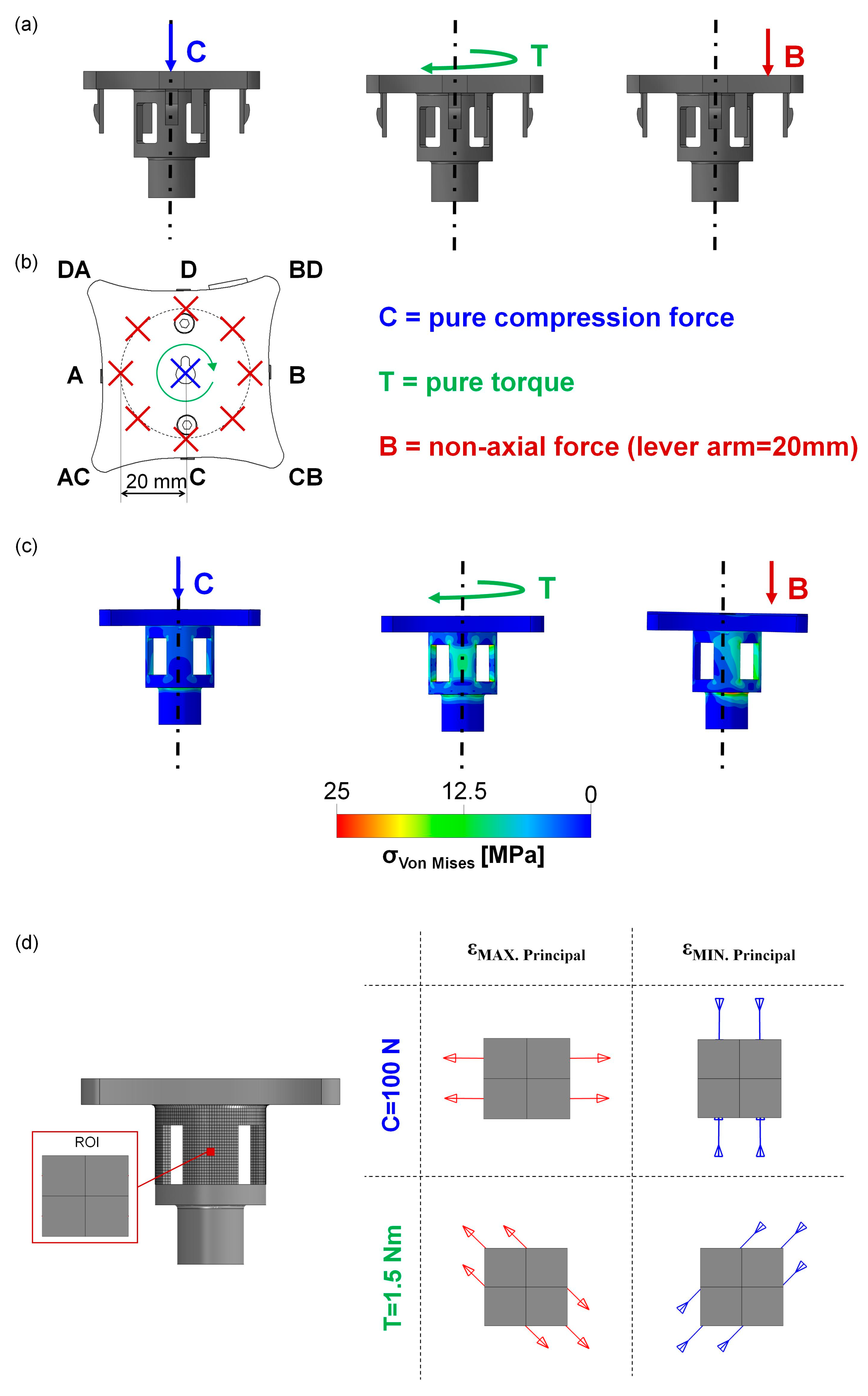
Figure 1. Optical analysis of the forks. Anterior and lateral comparison between an SI used 10 times and a CAD model.
Biomechanics 05 00026 g001
Figure 2. (a) The forks instrument and the Beat Plug coupled in the final part with the detail of the Beat Plug only; (b) the measurement system (MS) and the detail of all the components (sensitive element, cover, and the cap); (c) the only sensitive element used for the numerical analysis with the hexahedral mesh used for the central part in detail.
Biomechanics 05 00026 g002
Figure 3. (a) The three different configurations of the load and (b) the schematic details; (c) the von Mises color maps at the end of the three loading conditions; (d) a schematic and qualitative representation of the maximum and minimum principal deformation directions (εMAX. Principal and εMIN. Principal, respectively) in correspondence with the region of interest (ROI), particularly where the SG could be glued.
Biomechanics 05 00026 g003
Figure 4. (a) The sensitive element of the MS with red dots in the four positions of the SG rosettes (A, B, C, and D) as well as a scheme of the SG rosettes in detail with three different grids oriented at 0°, 45°, and −45°; (b) the 3D-printed sensitive elements with the glued-on SG rosettes and a zoom of this in detail with the three differently oriented grids.
Biomechanics 05 00026 g004
Figure 5. (a) The experimental test procedure during the implantation, with the curvature that was imposed in detail (c); (b) experimental test setup: (1) laptop; (2) MX840B HBM amplifier system; (3) Sis; (4) box containing the dummy SGs; (5) electrical connection; (6) MS; (7) Sawbone spine positioned; (d) on the left, the first implantation cage; on the right, the second one; (e) a scheme of the boundary conditions measured during the test; (f) axial force–time curves of the forks at the C3-C3 level. The continuum line for the right insertion, and the dotted line for the left insertion; (g) torque–time curves of the forks at the C3-C3 level; (h) bending moment–time curves of the forks at the C3-C3 level with different colors corresponding to different directions of moments (e). The continuum line and circles indicate the right insertion, while the dotted line and squares indicate the left insertion.
Biomechanics 05 00026 g005
Figure 6. The experimental test setups on the left, and the results in terms of the average axial deformation (εAVG [μm/m]) and average torsional deformation (εT_AVG [μm/m]) in the loading and unloading configurations and the calibration curves of the pure axial compression test (a), pure torsion test (b), and non-axial compression test (c) on the right.
Biomechanics 05 00026 g006
Figure 7. The axial force (on the left) and the torque (on the right) recorded during the experimental test for MS suitability using the chisel (a), forks (b), and reamer (c) SIs.
Biomechanics 05 00026 g007
Table 1. Parameters (the rate, the sampling frequency, and the detail of the cycles) of the calibration experimental test are reported.
RateSampling FrequencyProtocols
Case CPure compression force1 mm/min10 Hz5 loading–unloading cycles (10–100 N)
Case TPure torque1°/min10 Hz2 loading–unloading cycles (−1.5–+1.5 Nm)
Case BNon-axial force (bending)1 mm/min10 Hz5 loading–unloading cycles (10–100 N)
Disclaimer/Publisher’s Note: The statements, opinions and data contained in all publications are solely those of the individual author(s) and contributor(s) and not of MDPI and/or the editor(s). MDPI and/or the editor(s) disclaim responsibility for any injury to people or property resulting from any ideas, methods, instructions or products referred to in the content.

