1. Introduction
The use of human transportation has been around for a long time. Carrying heavy loads with bodies is unavoidable, even though it is the 21st century [
1,
2]. Furthermore, there has not been much advancement in heavy-load-carrying techniques since Antiquity, including holding objects in the hands, hanging packs from the shoulders, and balancing burdens on the head [
3,
4,
5]. Different powered exoskeletons [
6,
7,
8,
9,
10,
11,
12] and unpowered exoskeletons [
13,
14,
15,
16,
17,
18] have also been created as a result of technological advancement. The most comprehensive and cost-effective method is still a backpack. People have created a variety of backpack designs to increase comfort and reduce energy use, such as adding a belt to shift some of the weight to the waist and improving back comfort by including a suspended carrying system.
In daily life, the backpack is a piece of extensive and useful transportation equipment. A person’s hip travels vertically by 5–7 cm during movement [
19]. Because it is fixedly attached to the body, the backpack travels vertically in synchrony with the body and has the same amplitude as the body. The vertical motion of the backpack causes extra acceleration force on the wearer [
20], culminating in a peak force larger than the gravity of the backpack. Suspended-load backpacks (SUSBs) based on forced vibration have recently been developed [
21]. The SUSB differs from ordinary backpacks in that elastic components have been included. When the SUSB’s natural frequency is rather lower than the frequency of running or walking, the SUSB can effectively reduce the peak force of the load on the body and the body’s energy consumption [
21,
22,
23,
24,
25]. As shown in
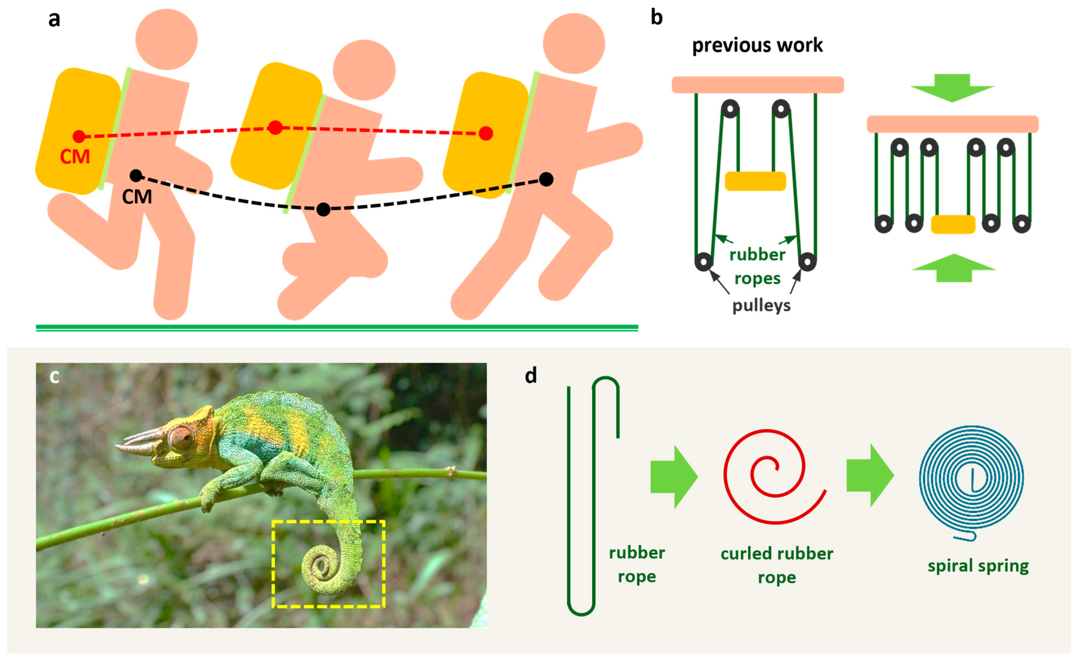
Figure 1a, the red dotted line is the trajectory of the center of mass (CM) of the SUSB, and the black dotted line the trajectory of the CM of the body. The SUSB’s vertical movement amplitude is less than that of the body. When the SUSB’s natural frequency approaches the frequency of motion, the peak force and energy consumption rise instead [
26].
Where there is no electricity supply, such as in the wilderness, it is necessary to have your own power generation equipment. Triboelectric nanogenerators (TENGs), based on electrostatic induction and contact initiation, can convert mechanical energy in the environment into electrical energy. Since the birth of TENGs, there has been a rapid development of TENGs for energy scavenging [
27]. TENGs are widely applied in wearable devices, self-powered sensors, and blue energy because of their advantages of low cost, light weight, high output power, and simple fabrication [
28,
29,
30,
31,
32,
33,
34,
35,
36]. The large amount of mechanical energy generated by SUSBs during motion has not been utilized. It is possible to equip TENGs in SUSBs to convert the mechanical energy during motion into electrical energy. How to equip TENGs in SUSBs is the focus of research.
SUSBs and exoskeletons are not in competition. They can be assembled together to reduce the carrying cost. Next, we focus on a literature survey on SUSBs. In 2007, Rome et al. designed a SUSB with rubber ropes and pulleys as elastic components to reduce human energy consumption during walking [
21]. Foissac et al. developed a single-degree-of-freedom spring–mass–damper model for the vertical motion of the SUSB [
26]. Hoover et al. stated that for a given load and walking frequency, the smaller the natural frequency of the SUSB, the better the suspension effect [
22]. Harandi et al. designed a nonlinear stiffness system for the SUSB with low dynamic stiffness and high static stiffness [
37]. They performed theoretical and software analysis of the nonlinear stiffness system and did not fabricate a prototype of the SUSB. Yang et al. designed a SUSB with rubber ropes and pulleys as the elastic components and converted the mechanical energy into electrical energy by TENG [
25].
The natural frequency is determined by the elastic components of SUSBs. It is currently common to use rubber ropes and pulleys as elastic components. To make the natural frequency small enough, rubber ropes and pulleys require sufficient space. This leads to the large size of SUSB. Backpack carrying has been shown to constitute a considerable daily “occupational” load on the spine in schoolchildren [
38]. The current SUSB is large and not suitable for schoolchildren to carry. The only way to reduce the size of the SUSBs is to add pulleys to make the rubber ropes wrap more times (
Figure 1b). However, the increase in pulleys complicates the structure of the SUSB and reduces its reliability. Chameleons have long tails, which are usually rolled up (
Figure 1c). Compared with a straight tail, a rolled-up tail rolled can save a lot of space. If the rubber rope is rolled up, it can also save a lot of space. However, the rolled-up rubber rope cannot be used. Considering that the spiral spring and the rolled-up rubber rope have similar shapes (
Figure 1d), we replace the rubber ropes with a spiral spring as the new elastic component, which reduces the volume of the SUSB without increasing the number of pulleys.
Rubber ropes are stretched longer after loads are added and, therefore, require large spaces. Assuming that the original lengths of the rubber ropes are the same, the rubber rope that is stretched longer has a smaller tensile stiffness for a given load. Therefore, a rubber cord with smaller stiffness requires more space. In contrast to rubber ropes, spiral springs occupy almost the same amount of space before and after the load is added. This is another important reason for the space-saving design of spiral springs. Yang et al. designed a flexible connection system based on rubber ropes for SUSB occupying an area of 420 mm*300 mm [
25]. The area occupied by the flexible connection system of the pre-compression SUSB based on pre-compression springs in Part 1 is 450 mm*300 mm. The flexible connection system of SUSB based on spiral springs occupies an area of 332 mm*170 mm, which is much less space than the previous two. As shown in
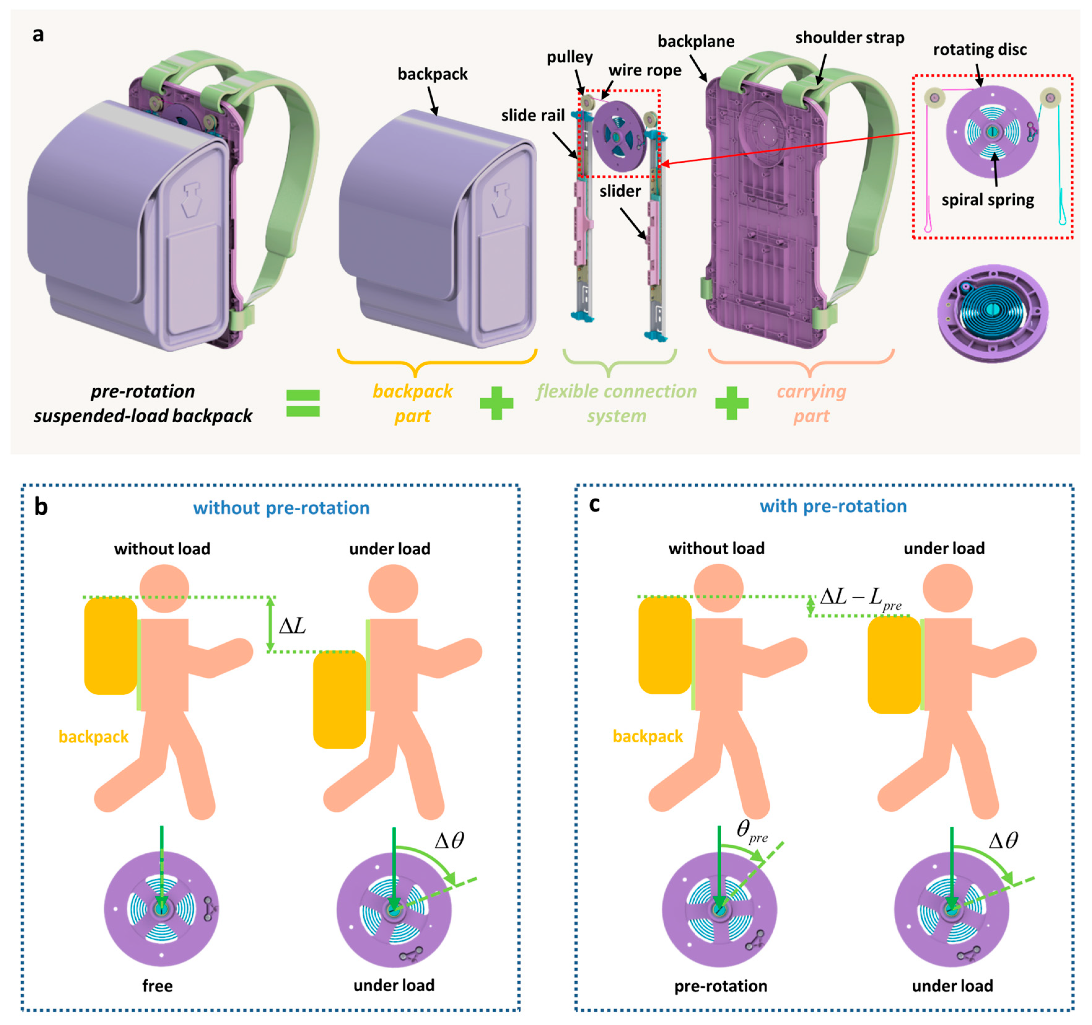
Figure 2a, the length of the SUSB flexible connection system depends mainly on the length of the slide rail. The diameter of the rotating disc, which works in conjunction with the spiral spring, is only 100 mm.
The aging of the rubber material causes the rubber ropes of SUSBs to break easily after a long time of use. We use spiral springs as the elastic component of the SUSB to avoid the inconvenience of material aging. The lower the stiffness of the spiral spring, the farther the backpack slides downward. In order to avoid the backpack sliding downward to an uncomfortable position, we propose a pre-rotation design that can adjust the downward sliding distance of the backpack. Previous studies have not focused on this point. The sliding TENG mounted on SUSBs in Yang et al.’s study is suitable for all SUSBs [
25]. According to the characteristics of a spiral-spring-based SUSB, we have added rotating TENG, which is our innovation in TENG design.
In this study, we propose a design strategy of using a pre-rotation spiral spring as a pre-rotation of the elastic part. The pre-rotation design not only has the advantages of avoiding the inconvenience of material aging and the ability to adjust the downward sliding distance of the backpack but also greatly saves the space occupied by the elastic components, which can be adopted by small SUSBs. We have developed a theoretical model of the pre-rotation suspended-load backpacks (PR-SUSBs) and experimentally confirmed the performance of the PR-SUSBs. This work provides a unique design approach for small SUSBs and small suspended-load devices. And the relative motion between the components inside the SUSB has a huge potential to be used by TENGs for energy scavenging.
2. Results and Discussion
Figure 2a illustrates a schematic representation of the PR-SUSB, which is made up of three parts: the backpack part, the carrying part, and the flexible connection system. The backpack part is capable of sliding relative to the carrying part through the flexible connection system. The load is packed in the backpack of the backpack part. The carrying part, which is made of a backplane and shoulder straps, is used to connect the body. The most critical part of the flexible connection system is the elastic components. The elastic components determine the natural frequency of the PR-SUSBs. In contrast to previous SUSBs, we adopt pre-rotation spiral springs instead of rubber ropes and pulleys as the elastic components. The metal elastic components are not as susceptible to material aging as rubber material. One end of the spiral spring is fixed on the central axis of the rotating disc, and another end is hooked on a cylinder on the periphery of the rotating disc. The central axis of the rotating disc is fixedly mounted on the backplane. And the periphery of the rotating disc can rotate. The periphery of the rotating disc is connected to the sliders by wire ropes. The slider is free to slide on the slide rail. The sliders and pulleys of the flexible connection system are fixedly mounted in the corresponding positions of the backplane, and the backpack is fixedly connected to the sliders of the flexible connection system. The pre-rotation spiral spring is further tightened by the gravity of the load. During the movement, the relative motion between the backpack and the body causes the pre-rotation spiral spring to be rotated back and forth. The lock switch on each of the slide rails can lock the sliders and prevent the sliders from sliding, which turns the PR-SUSB into a locked backpack.
The pre-rotation in the pre-rotation spiral spring indicates that the spring inserted in the flexible connection system has already rotated without load. If the spiral spring is not pre-rotated when installed, the spiral spring in the flexible connection system stays force-free. The distance the backpack slides down after loading is
, as shown in
Figure 2b. Because of the long downward sliding distance, the backpack may slide down to an uncomfortable position on the back, such as the hip position. Walking might be challenging for the wearer. The pre-rotation spiral spring has the pre-rotation angle
without load, as shown in
Figure 2c. Under load, the downward sliding distance of the backpack becomes
. As a result, the pre-rotation design may modify the distance of sliding down to prevent the backpack from sliding down to an unpleasant wearing posture, thereby enhancing wearing comfort. It is easy to obtain the relationship between
and pre-rotation angle
, which can be expressed as Equation (1) below:
where the radius of the rotating disc is given by
.
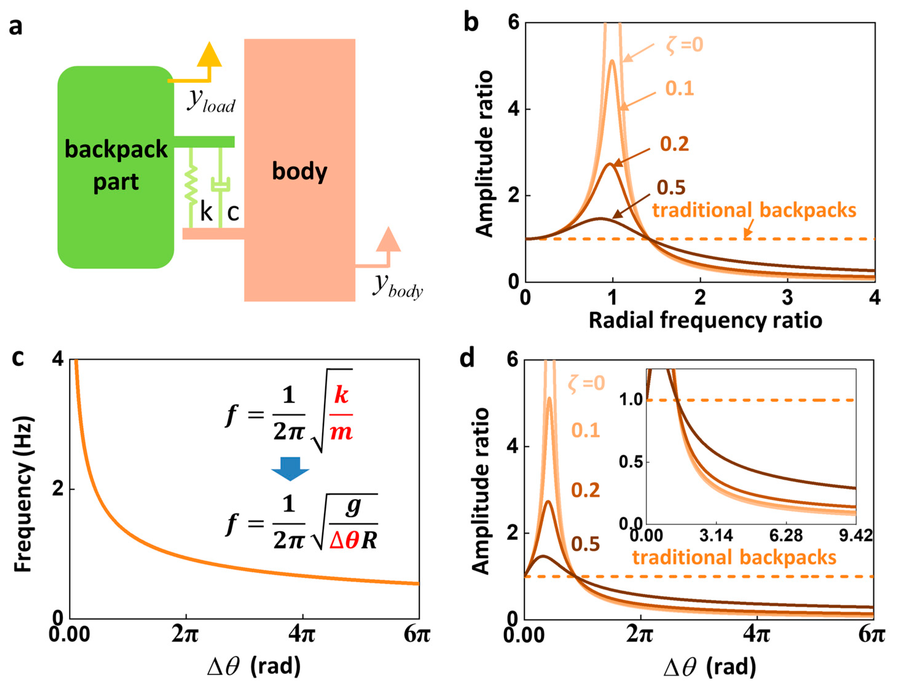
We built the single-degree-of-freedom spring–mass–damper model in displacement excitation to study the vertical motion of PR-SUSB, as illustrated in
Figure 3a. This vibration model’s equation of motion is
where
and
represent the movement of the body and the backpack part, respectively. The mass of the backpack part is
. The stiffness
and damping
are the equivalent spring constant and damping coefficient. The movement of the body can be described as
, where amplitude, radial frequency, and time are given by
,
, and
. The PR-SUSB’s natural radial frequency is
. The response of the backpack part can be described in Equation (3) below:
where the amplitude of vibration is denoted by
and the relative phase shift of the vibration between the backpack part and body is denoted by
. By solving Equation (2), the amplitude ratio
and the phase shift are obtained, as shown in Equations (4) and (5) below:
where the radial frequency ratio and the damping ratio are denoted by
and
, respectively. The traditional backpack is thought to have infinite rigidity since it contains no elastic component. Therefore, the radial frequency ratio
of the traditional backpack is regarded as 0, and the amplitude ratio is assumed to be 1. The force acting on the body from the PR-SUSB is
It is found by Equation (7) that the PR-SUSB has the effect of reducing the peak force when the amplitude ratio
is less than 1.
Figure 3b illustrates the relationship between amplitude ratio
and radial frequency ratio
under different damping ratios, which is obtained from Equation (4). The amplitude ratio
is less than 1 when the radial frequency ratio
is more than
, and it decreases as the radial frequency ratio
rises. The radial frequency ratio of the PR-SUSB
should be larger than
in order for it to produce the suspension effect. Furthermore, the greater the radial frequency ratio
, the better the suspension effect. The resistance in flexible connection systems is usually induced by friction, such as the friction between the pulley and the fixed axis, the friction between the pulley and the wire rope, the friction between the slide rail and the slider, and so on. Different damping ratios result in different amplitude ratio–radial frequency ratio curves. In the case of a certain radial frequency ratio, the smaller the damping ratio, the smaller the amplitude ratio, which means the better the suspension effect. Therefore, the friction between the components should be minimized when the SUSB is designed. The damping ratio cannot be measured directly. The damping ratio can be obtained by inverting the amplitude ratio–radial frequency ratio curve.
The natural frequency of the PR-SUSB is
The natural frequency of the PR-SUSB is simultaneously defined by two parameters according to Equation (8): the mass of the weight
and the stiffness
of the PR-SUSB. For the specific example of the PR-SUSB, a simplification is performed. Hooker’s law states that we can obtain
When the PR-SUSB is not loaded, there is a pre-rotation load on the spiral spring due to the limitations of the flexible connection system. When the PR-SUSB is under load, the spiral spring is rotated and is no longer limited by the flexible connection system; thus, there is no pre-rotation load. The theoretical analysis model analyzes the motion of the PR-SUSB under load. Therefore, there is no such parameter as pre-rotation load in the theoretical analysis model. The pre-rotation load is a part of mg, as shown in Equation (9). Substituting Equation (9) into Equation (8),
As shown in Equation (10), the natural frequency of the PR-SUSB is solely dependent on one parameter, the amount
. The lower the natural frequency of the SUSB, the better the suspension effect of the SUSB. According to the previous equation, Equation (8), the natural frequency of the SUSB depends not only on the stiffness of the elastic components in the design of the SUSB but also on the mass of the load. When comparing the natural frequencies of PR-SUSBs with different stiffnesses under different masses of loads, it is necessary to calculate by substituting the respective load masses and stiffnesses into Equation (8) in order to know which case has a lower natural frequency. With the newly obtained Equation (10) in this study, we can know that the natural frequency of the PR-SUSB is only related to the amount
. When it is necessary to compare the natural frequencies in different cases, it is only necessary to compare the amount
. This simplifies the process of evaluating the performance of the PR-SUSB compared to before. According to Equation (10),
Figure 3c depicts the relationship between the amount
and the natural frequency
, where the natural frequency
reduces as the amount
rises. The relationship between the amount
and the amplitude ratio
is equivalent to the relationship between the radial frequency ratio
and the amplitude ratio
. When the excitation frequency is 2 Hz,
Figure 3d shows the relationship between the amount
and the amplitude ratio
under different damping ratio.
Figure 3d’s inset is an enlargement of
Figure 3d that depicts the trend of the amount
for amplitude ratios
less than 1. The amplitude ratio
falls as the amount
rises. Different damping ratios result in different amplitude ratio–amount
curves. In the case of a certain amount
, the smaller the damping ratio, the smaller the amplitude ratio, which means the better the suspension effect.
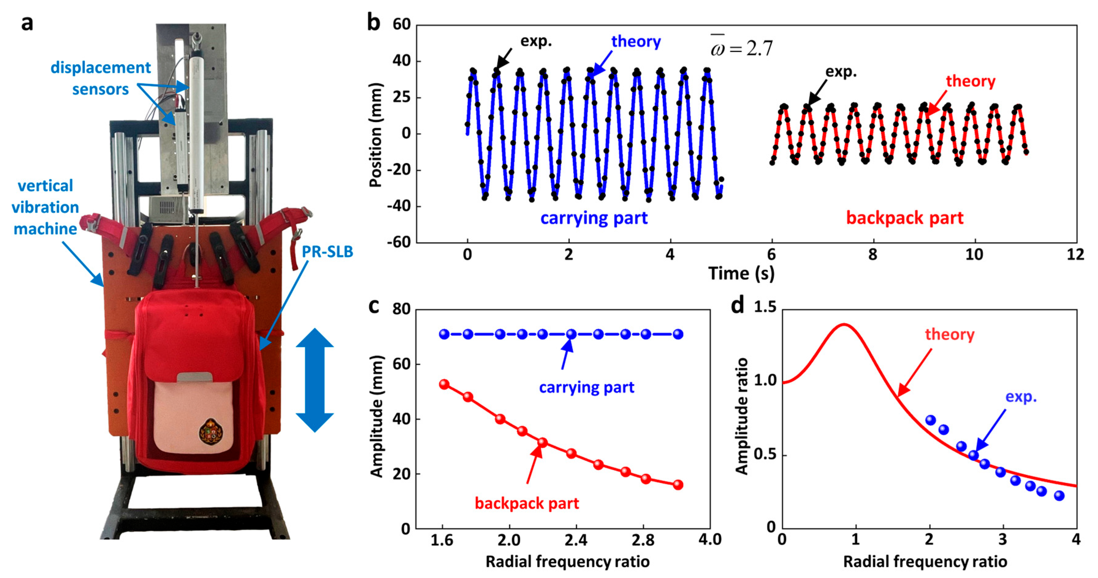
A PR-SUSB was constructed, and its suspension performance was experimentally assessed to validate the success of the pre-rotation design strategy. The radius of the PR-SUSB’s rotating disc is 45 mm. Under the load
, the amount
and the natural frequency
of the PR-SUSB are 0.79 Hz. We conducted experimental measurements on the PR-SUSB with a 5 kg load. The carrying part of PR-SUSB was fixed on a self-made vertical vibration machine (
Figure 4a). The excitation amplitude generated by the vertical vibration machine throughout the experiment is 71 mm. Two displacement sensors based on sliding resistors are employed to measure the vertical displacement of the carrying part and backpack part of the PR-SUSB, respectively. Experimental data of the resistance values of the two displacement sensors are recorded by electricity meter (34972A, Keysight, Santa Rosa, CA, USA). The frequency measurement is carried out by means of displacement sensors. Firstly, the displacement sensor is used to obtain the curve of position change with time during vertical vibration. Then, the position time curve is analyzed. The time difference between a peak and a subsequent peak is a period of vertical vibration, and the frequency of vertical vibration is calculated from the period of vertical vibration. The self-made vertical vibration machine converts the rotary motion of the motor into reciprocating linear motion by means of the slider–crank mechanism, which consists of a crank, a connecting rod, and a slider. The slider–crank mechanism is mounted on the back of the self-made vertical vibration machine and is not visible in
Figure 4a. The top of the displacement sensor is not a ball joint but a ring clasp for fixation. The ring clasp at the top of the displacement sensor and the self-made vertical vibration machine are fully fixed together with several nuts so that no rotational deviation occurs.
Because the traditional backpack is regarded as being attached to the source of excitement, the traditional backpack has the same displacement as the carrying part. In the case of a radial frequency ratio of 2.7, the experimental results show that the amplitude of the carrying part is 71 mm, which is much larger than the amplitude of the backpack part of 32 mm, as shown in
Figure 4b. This indicates that the PR-SUSB has a good suspension effect at a frequency ratio of 2.7. The solid lines in
Figure 4b represent the theoretical results. The displacement theory curve of the carrying part (blue solid line) is expressed as a sine function. It is found that the theoretical curve fits well with the experimental results. The theoretical results for the backpack part (red solid line) are derived from the theoretical curves obtained by fitting in the following. The experimental and theoretical results of the backpack part are well in accordance with each other. The experimental results show that the carrying part’s amplitude remains constant while the backpack part’s amplitude declines when the frequency ratio goes down, as illustrated in
Figure 4c. The experimental results are in agreement with the theoretical prediction. By fitting the experimental results of
Figure 4c into Equation (4), the damping ratio (
) of the PR-SUSB and the theoretical curve of amplitude ratio to radial frequency ratio of the PR-SUSB are obtained (
Figure 4d).
Since the backpack part contains the load, there will be a bending moment on some components. If the stiffness of these components is small, these components will produce bending deformations. These components have been designed with the effect of bending moments in mind, so they are designed to have a large stiffness and can be considered rigid bodies. Rigid bodies do not suffer from bending deformation. The bending moment of the load in the backpack part also affects the connection between the components. The backpack part is fixed to the flexible connection system by the sliders. The sliders slide on the slide rails. The slide rails are fixed to the flexible connection system. The flexible connection system is fixedly connected to the carrying part by the backplane. The fixed connection can also be regarded as a rigid body. The bending moment generated by the load in the backpack part only affects the non-fixed connection between the slider and the slide rail. There is sliding friction between the slider and the slide rail. The greater the bending moment, the greater the sliding friction. The increase in sliding friction is reflected in the equation of motion as an increase in the damping ratio. As shown in
Figure 4d, the magnitude of the damping ratio is derived from the amplitude ratio–frequency ratio relationship obtained from experiments.
The carrying part and the backpack part of the PR-SUSB generate relative motion in the vertical direction during movement. The sliding TENG is used to scavenge the mechanical energy generated by the relative motion of the carrying part and the backpack part. During the motion, the rotating disk rotates back and forth, and the backplane remains static. A disk-shaped rotating TENG can be installed between the rotating disk and the backplane. The PR-SUSB can use these two TENGs to scavenge energy during movement. The collected power is stored in the battery by the power management module. The battery is utilized to charge small electronic devices. We are willing to turn the energy-scavenging potential into reality in our future work. The amount of energy scavenged by PR-SUSB can be referred to in the study of Yang et al. [
25]. Yang et al. designed a rubber-rope-based SUSB that utilizes a sliding TENG to scavenge the energy generated by the relative motion of the carrying part and the backpack part. Their instantaneous power to scavenge energy is 0.434 W. The PR-SUSB has one more kind of TENG than Yang’s SUSB.


