Article

Suspended-Load Backpacks to Reduce the Cost of Carrying Loads with Energy Scavenging Potential—Part 1: Pre-Compression Design

1
State Key Laboratory of Nonlinear Mechanics, Institute of Mechanics, Chinese Academy of Sciences, Beijing 100190, China
2
School of Engineering Science, University of Chinese Academy of Sciences, Beijing 100049, China
3
Zhongke Carrying Equipment Technology Co., Ltd., Beijing 101407, China
4
CAS Center for Excellence in Nanoscience, Beijing Key Laboratory of Micro-Nano Energy and Sensor, Beijing Institute of Nanoenergy and Nanosystems, Chinese Academy of Sciences, Beijing 101400, China
5
School of Nanoscience and Technology, University of Chinese Academy of Sciences, Beijing 100049, China
*
Author to whom correspondence should be addressed.
Nanoenergy Adv. 2023, 3(3), 259-270; https://doi.org/10.3390/nanoenergyadv3030014
Submission received: 9 May 2023 / Revised: 17 August 2023 / Accepted: 31 August 2023 / Published: 4 September 2023

Abstract

:
Backpack transportation is commonly used in daily life. Reducing the cost of the backpack on the human body is a widely researched subject. Suspended-load backpacks (SUSBs) based on forced vibration can effectively reduce the cost during movement. The intrinsic frequency of the SUSB is determined by the elastic components of the SUSB. Previous researchers used pulleys and rubber ropes as the elastic components. We propose a pre-compression design strategy based on pre-compression springs. Compared with previous studies, the use of pre-compression springs as elastic elements improves the reliability of the SUSB structure, avoids the inconvenience of nonlinearity and material aging, and adds the ability to flexibly adjust the sliding distance of the backpack. Moreover, previous studies utilized the relative motion between the carrying part and the backpack part to scavenge the vibration energy. We propose that the vibration energy can also be scavenged by the relative motion between the elastic components. A theoretical model is developed for the pre-compression SUSB. We experimentally confirm the performance of the pre-compression SUSB. This work provides new design ideas for SUSBs with reduced energy costs. In Part 2, we propose a bio-inspired pre-rotation design that has the advantage of occupying less space.

1. Introduction

1.1. Background

The transport of goods is not only a necessary condition for advanced business activities but also part of people’s daily lives. Usually, people use animals [1] and machines [2,3,4,5] to transport goods. However, the carrying of heavy loads by the body is inevitable [6,7]. In long-term practice, many methods of carrying heavy loads have been developed, such as balancing loads on the head, suspending backpacks from the shoulders, and holding objects in the hands [8,9]. Recently, various powered exoskeletons [10,11,12,13] and unpowered exoskeletons [14,15,16] have also been developed. The backpack remains the most extensive and economical method. In order to make the backpack more comfortable and energy-saving, many designs have been proposed, such as adding a belt to transfer part of the weight to the waist and increasing the comfort of the back by adding a suspended carrying system.
Due to the limitation of battery storage capacity, it is important to rely on one’s own power generation equipment in the absence of an external power supply. Electromagnetic generators, piezoelectric generators, and triboelectric nanogenerators (TENGs) are commonly utilized to scavenge energy from the environment [17,18,19,20,21,22,23]. TENGs have the advantages of high output power, simple fabrication, low costs, and a light weight. Since the emergence of TENGs in 2012, they have been developed rapidly for energy scavenging, which has been widely employed in the fields of wearable devices, self-powered sensors, and blue energy [24,25,26,27,28,29].

1.2. Formulation of the Problem of Interest for This Investigation

During locomotion, a person’s hip moves vertically by 5–7 cm [30]. The backpack moves vertically in synchronization with the body and has the same amplitude as the body since it is fixedly connected to it. The vertical motion of the backpack generates an additional acceleration force on the wearer [31], resulting in the wearer being subjected to a peak force that is greater than the gravity of the backpack. Recently, suspended-load backpacks (SUSBs) based on forced vibration have been proposed [32]. Compared to a traditional backpack, the SUSB has newly added elastic components. When the intrinsic frequency of the SUSB is slightly smaller than the frequency of walking or running, the SUSB can effectively reduce the maximum force of the load on the body and reduce the energy consumption of the body [32,33,34,35,36]. As shown in Figure 1a, the red dotted line is the trajectory of the center of mass (CM) of the SUSB, and the black dotted line the trajectory of the CM of the body. The vertical movement amplitude of the SUSB is smaller than that of the body. When the intrinsic frequency of the SUSB is close to the frequency of the motion, the peak force and energy consumption increase instead [37]. The question of how to adjust the intrinsic frequency of the SUSB so that the vertical movement amplitude is smaller than the vertical movement amplitude of the human body is a major challenge in the research.
The SUSB continues to vibrate during its usage. The vibration energy is not utilized efficiently. TENGs are useful for the conversion of vibration energy into electrical energy. The vibration energy can be collected by installing TENGs on SUSBs to supply energy to small electronic devices. The question of how to attach energy-harvesting devices to the SUSB is another challenge in the research.

1.3. Literature Survey

Rome et al., in 2007, designed an SUSB that reduces the body’s metabolism during movement [32]. Foissac et al. predicted the vertical motion of SUSBs with a single-degree-of-freedom model [37]. They stated that the resonance effect can lead to a modified walking pattern and an increased metabolic cost. Hoover et al. suggested that SUSBs should be designed with lower stiffness values than the performance stiffness for a given backpack load and frequency of motion [33]. Ackerman et al. explained the different experimental energy results found when carrying SUSBs and systematically investigated the effect of SUSB parameters on the energy cost of human walking [35]. Li et al. employed a single-degree-of-freedom model to quantitatively assess the effect of the stiffness and damping of SUSBs on the body’s energy cost [34]. Harandi et al. designed a nonlinear stiffness system with low dynamic stiffness and high static stiffness [38]. This mechanism included one horizontal and two oblique springs. They conducted theoretical and software analyses of the nonlinear stiffness systems. Yang et al. designed an SUSB with adjustable stiffness utilizing an electric motor [39]. The stiffness of the system was adjusted to appropriate values at different speeds to improve the metabolic cost reduction effect of SUSBs. Yang et al. reported on an SUSB based on a TENG for the harvesting of wasted energy from human movement [36]. Fan et al. designed an SUSB based on an innovative flexible mechanical motion rectifier [40]. The flexible mechanical motion rectifier was composed of an inelastic strap, an elastic strap, a shaft with a double-layered plectrum, and a rotor.

1.4. Scope and Contribution of This Study

The intrinsic frequency of the SUSB has a significant impact on the peak force and energy consumption. The intrinsic frequency of the SUSB is determined by the elastic components of the SUSB, so the design of the elastic components is crucial. Previous researchers have used pulleys and rubber ropes as the elastic components of SUSBs (Figure 1b) [30,36]. This complicates the structure of the SUSB and reduces its reliability. Rubber ropes also suffer from a nonlinear stress–strain curve and material aging [41,42,43]. The deformation range of the rubber rope during the use of the SUSB is generally small, so the problem of the nonlinearity of the stress–strain curve is not obvious and will not affect the SUSB. When the load on the SUSB varies widely, the deformation range of the rubber rope also changes significantly. Since the stress–strain curve of the rubber rope is nonlinear, the stiffness of the rubber rope needs to be reevaluated at this time. This can complicate the design of the SUSB. The aging of the rubber material will cause the rubber rope to break easily after the SUSB is used for a long time. We adopted pre-compression springs as the elastic components of the SUSB. The absence of pulleys and rubber ropes in the elastic components reduces the complexity of the SUSB structure and avoids the inconvenience of nonlinearity and material aging.
The smaller the stiffness of the elastic components of the SUSB, the smaller the peak force and energy consumption. The backpack will slide downward with the deformation of the elastic components. In order to avoid the backpack sliding down to an uncomfortable position, we propose a pre-compression design that can adjust the downward sliding distance of the backpack. This problem has not been studied by other researchers.
Yang et al. added a sliding TENG to a rubber-rope-based SUSB [36]. Because this TENG scavenges energy via the relative movement between the carrying part and the backpack part, the TENG is universal to all SUSBs. In addition to the universal TENG introduced by Yang, our SUSB can be equipped with a TENG in the elastic components, which scavenges energy via the relative movement between the elastic components. This represents a major innovation in TENG design.

1.5. Organization of the Paper

The theoretical analysis of the pre-compression SUSB is carried out. We experimentally confirm the performance of the pre-compression SUSB. The effect of the buckling behavior of the spring on the suspension effect is investigated. This work provides a new design concept for an SUSB with reduced maximum forces and energy consumption. The vibrational energy of the pre-compression SUSB has potential to be scavenged. In Part 2, we propose a pre-rotation design that uses a pre-rotation spiral spring as the elastic component of the SUSB. Since the spiral spring will only rotate and not elongate when it is under force, the spiral spring occupies less space. A pre-rotation SUSB has the advantage of saving space. The theoretical analysis of the pre-rotation SUSB is carried out. The performance of the pre-rotation SUSB is verified experimentally. The corresponding energy scavenging design is provided for the pre-rotation SUSB. The bio-inspired pre-rotation design provides a unique design approach for small SUSBs and small suspended-load devices.

2. Methods

Experiments and Electrical Measurements: The pre-compression SUSB was mounted on a self-made vertical vibration machine that could perform low-frequency and large-amplitude experiments. Two displacement sensors mounted on the machine and the pre-compression SUSB were used to measure the displacement of the carrying part and backpack part, respectively. Experimental data from displacement sensors were recorded by a voltmeter (34972A, Keysight, Santa Rosa, CA, USA) at a constant voltage output from a power meter.
Finite Element Analysis (FEA): We selected ABAQUS to perform FEA. The diameters of the support poles were 2.5 mm, 3.5 mm, 4.5 mm, and 5.5 mm. The springs, composed of piano wire, and support poles composed of stainless steel were treated as linear elastic materials, where the Poisson’s ratio and Young’s modulus of the piano wire and stainless steel were 200 GPa and 0.3, respectively. The FEA model employed an analysis step whose procedure type was static general. The analysis step also included the nonlinear effects of large deformations and displacements. The bottom of the spring was clamped and the displacement load was applied at the top. The support pole was clamped at the top. The spring and support pole were set up as solid parts with the hexahedron elements C3D8R.

3. Results and Discussion

We designed a pre-compression SUSB (Figure 1c), which has three components: a backpack part to carry the load, a carrying part to connect to the body, and a flexible connection system to connect the backpack part and the carrying part. The backpack part is capable of sliding relative to the carrying part through the flexible connection system. The most critical part of the flexible connection system is the elastic components. Compared with the previous SUSB, we adopt the pre-compression design strategy, replacing the elastic components from the pulleys and rubber ropes with pre-compression springs. Metal springs not only have a linear stress–strain curve but also do not suffer from material aging. Multiple pre-compression springs are arranged in parallel in the flexible connection system. In order to avoid the excessive buckling of the pre-compression spring during compression, a support rod slightly smaller than the inner diameter of the pre-compression spring is inserted into the pre-compression spring. The flexible connection system has a slide rail on each side. The slide rails have two sliders that slide vertically. The sliders are fixedly connected to the backpack. Under the action of the backpack’s gravity, the pre-compression springs are further compressed. The relative movement between the body and backpack during travel causes the spring to compress and stretch. The other side of the two sliders is connected fixedly to the back plate of the backpack. A lock switch on the slide can lock the slider and prevent it from sliding. After locking, the SUSB becomes a traditional backpack. The height of the pre-compression spring when it is compressed to its shortest length is called the solid height, which is also the height of the pre-compression spring when all the coils touch each other. The solid height takes up a certain amount of space, which makes it difficult to reduce the space for the pre-compression SUSB.
The pre-compression in the pre-compression spring means that the spring installed in the flexible connection system is already compressed without a load. If the spring is not pre-compressed when installed, then the spring installed in the flexible connection system remains at its original length L 0 . The distance that the backpack slides after loading is equal to the amount of compression of the spring Δ L , as shown in Figure 2a. The backpack and the flexible connection system are fixedly connected by sliders (short red line). Because of the long downward sliding distance, the backpack may slide down to an uncomfortable position on the back, such as the hip position. This leads to uncomfortable walking. The pre-compression spring has the pre-compression amount L p r e without a load, as shown in Figure 2b. Under a load, the downward sliding distance of the backpack becomes Δ L L p r e . Therefore, the pre-compression design can adjust the distance of downward sliding to prevent the backpack from sliding down to an uncomfortable position, improving the wear comfort. Previous studies have not mentioned this [30,36].
To analyze the vertical motion of the pre-compression SUSB during locomotion, we established a spring–mass–damper model in displacement excitation (Figure 3a) under the assumption that there is no relative movement between the body and the carrying part. The equation is
m d 2 y l o a d d t 2 + c ( d y l o a d d t d y b o d y d t ) + k ( y l o a d y b o d y ) = 0
where y b o d y is the displacement of the body’s center of mass. y l o a d is the displacement of the loaded backpack part. m is the mass of the backpack part. c is the damping coefficient. k is the stiffness coefficient. The displacement of the body is y b o d y = B sin ( ω t ) , where ω is the radial frequency and B is the amplitude. The natural radial frequency of the pre-compression SUSB is ω n = k / m . The displacement of the backpack part is
y l o a d = A sin ( ω t α )
whereby α is the relative phase shift and A is the amplitude. Solving the steady-state response of Equation (1) gives the amplitude ratio A / B and the phase shift shown in Equations (3) and (4) below:
A B = 1 + 4 ζ 2 ω ¯ 2 ( 1 ω ¯ 2 ) 2 + 4 ζ 2 ω ¯ 2
tan α = 2 ζ ω ¯ 3 1 ω ¯ 2 + 4 ζ 2 ω ¯ 2
where ω ¯ = ω / ω n is the radial frequency ratio and ζ = c / 2 m ω n is the damping ratio. Because there is no elastic component in the traditional backpack, the stiffness of the traditional backpack is considered to be infinite. Moreover, the radial frequency ratio ω ¯ of the traditional backpack is 0 and the amplitude ratio is 1. The force of the pre-compression SUSB on the body is
F b a c k p a c k = m g m d 2 y l o a d d t 2 = m g + m ω 2 A sin ( ω t α )
When sin ( ω t α ) = 1 , the peak force F b a c k p a c k is
F p e a k = m g + m ω 2 A = m g + m ω 2 B A B
When the amplitude ratio A / B is less than 1, the pre-compression SUSB has the effect of reducing the peak force. According to Equation (3), the relationship between amplitude ratio A / B and radial frequency ratio ω ¯ is as shown in Figure 3b. When the radial frequency ratio ω ¯ is larger than 2 , the amplitude ratio A / B is less than 1, and the ratio of amplitudes A / B falls as the radial frequency ratio ω ¯ rises. In order to allow the pre-compression SUSB to achieve the suspension effect, the design of the pre-compression SUSB should ensure that the radial frequency ratio ω ¯ is greater than 2 . The larger the radial frequency ratio ω ¯ , the better the suspension effect.
The natural frequency of the pre-compression SUSB is
f = ω 2 π = 1 2 π k m
From Equation (7), it can be found that the natural frequency of the pre-compression SUSB is jointly determined by two parameters, the mass of the weight m and the stiffness k of the pre-compression SUSB. A simplification is applied for the specific case of the pre-compression SUSB. According to Hooker’s law, we can obtain
Δ L = L p r e + Δ L L p r e = m g k
When the pre-compression SUSB is not loaded, there is a pre-compression load on the spring due to the limitations of the flexible connection system. When the pre-compression SUSB is under a load, the spring is compressed to a shorter length and is no longer limited by the flexible connection system; thus, there is no pre-compression load. The theoretical analysis model analyzes the motion of the pre-compression SUSB under a load. Therefore, there is no such parameter as the pre-compression load in the theoretical analysis model. The pre-compression load is a part of m g , as shown in Equation (8). Substituting Equation (8) into Equation (7),
f = 1 2 π g Δ L
As can be found from Equation (9), the natural frequency of the pre-compression SUSB is related to only one parameter, the compression amount Δ L . Equation (9) simplifies the process of evaluating the performance of the pre-compression SUSB. Figure 3c shows the relationship between the compression amount Δ L and the natural frequency f in Equation (9), where the natural frequency f decreases as the compression amount Δ L increases. The relationship between the compression amount Δ L and the amplitude ratio A / B is similar to the relationship between the radial frequency ratio ω ¯ and the amplitude ratio A / B . Figure 3d demonstrates the relationship between the compression amount Δ L and the amplitude ratio A / B when the excitation frequency is 2   Hz . The inset of Figure 3d is an enlargement of Figure 3d, illustrating the trend of the compression amount Δ L for amplitude ratios A / B less than 1. As the compression amount Δ L increases, the amplitude ratio A / B decreases.
For the purpose of verifying the feasibility of the pre-compression design strategy, we manufacture a pre-compression SUSB. The elastic components are composed of springs in parallel. The compression amount Δ L = 162   mm and the natural frequency f of the pre-compression backpack is 1.23   Hz under the load m = 25   kg . The origin length of the spring L 0 = 465   mm , and the pre-compression amount L p r e = 65   mm . The living space of the top of the spring L w = 140   mm ( L 2 = 70   mm , L 3 = 70   mm ) is much larger than the distance of the hip rising 50 70   mm on each step, avoiding the collision between the spring and the flexible connection system. The minimum working length L 1 = 224   mm is greater than the solid length of the spring.
To evaluate the performance of the pre-compression SUSB, we conduct a vertical vibration experiment. The excitation amplitude throughout the experiment is 49 mm. Since the carrying part is fixed to the excitation source, the carrying part has the same displacement as the excitation source. The traditional backpack can be considered as fixed on the body of the wearer. Thus, the comparison of the amplitude between the carrying part and the backpack part can be regarded as the comparison between the traditional backpack and the pre-compression SUSB. Figure 4b demonstrates the positions of the carrying part and the backpack part at a radial frequency ratio of 2.5. Theoretical results are shown as solid lines, and experimental results are shown as scattered points. Displacement sensors are essentially slide rheostats that have different amounts of resistance at different positions. The measured resistance value is converted into a voltage value under a constant voltage source. The displacement of the movement can be calculated from the voltage difference before and after the movement. Each scattered point represents a position. The sequential scattered points show the trajectory of the carrying part and the backpack part over time, resulting in movement in the vertical direction. The theoretical results for the backpack part are derived from the theoretical curves obtained by fitting in the following. The theoretical and experimental results are well matched. Rome et al. showed that the displacement of the carrying part is 68 mm and the displacement of the backpack part is 26.5 mm with a load of 27 kg [32]. The displacement of the backpack part is 38.7% of that of the carrying part. Yang et al. showed that the displacement of the carrying part is 35.111 mm and the displacement of the backpack part is 25.015 mm at a vibration frequency of 1.82 Hz [36]. The displacement of the backpack part is 71.2% of that of the carrying part. In our work, the amplitude of the backpack part (15 mm) is much smaller than that of the carrying part (49 mm). The displacement of the backpack part is 30.6% of that of the carrying part, which confirms that the pre-compression SUSB has a good suspension effect. The weight and gravity of the other components (the carrying part and flexible connection system) of the pre-compression SUSB are 3.2 kg and 31.36 N, respectively. In the study of Rome et al., in the case wherein the load is 27 kg and the displacement of the backpack part is 38.7% of the carrying part, the extra load of the traditional backpack is 154.5 N greater than that of the SUSB [32]. In our work, the load of the pre-compression SUSB is 25 kg and the displacement of the backpack part is 30.6% of the carrying part. Our conditions are similar to Rome et al.’s, so the extra load added by the other components is certainly less than that caused by a traditional backpack. We measured the position conditions of the carrying part and the backpack part for radial frequency ratios ranging from 1.55 to 2.67. The amplitudes of the movements were obtained by subtracting the highest point of the position from the lowest point of the position. Since one end of the displacement sensors is fixed with respect to the ground, the displacement amplitudes of the backpack part and the carrying part are both considered with respect to the ground. As shown in Figure 4c, as the radial frequency ratio decreases, the amplitude of the carrying part remains constant and the amplitude of the backpack part decreases, which is consistent with the theoretical prediction. It is illustrated in Figure 4d that the theoretical curve of the amplitude ratio versus the radial frequency ratio is obtained by fitting the amplitude values of the backpack part that were measured experimentally into the theoretical equation. The damping ratio of this SUSB ( ζ = 0 . 21 ) is also obtained by fitting.
Springs with large aspect ratios inevitably exhibit buckling behavior during compression. We insert a support pole with a similar diameter in the middle of the spring, effectively alleviating the phenomenon of spring buckling. It still can be observed that slight buckling occurs on the spring during compression. If the compression stiffness of the spring changes significantly, this will have a significant impact on the suspension effect of the pre-compression SUSB. Therefore, it is necessary to study the compression stiffness of the spring under limiting buckling. We perform FEA to investigate the changes in the compression stiffness of the spring with support poles of different diameters. The FEA deformation shapes at 30% strain can be seen in Figure 5a. As the diameter of the support pole becomes smaller, the degree of buckling of the spring becomes larger. As shown in Figure 5b, although the spring buckles during compression, the compression stiffness (slope in the strain–force curve) of the spring remains constant. It was originally thought that the compression stiffness of the spring under the small-diameter support pole would become much smaller. The FEA results show that the compression stiffness of the spring with a small-diameter support pole is not notably lower than that of the spring with a large-diameter support pole. This shows that the diameter of the support pole has little effect on the compression stiffness of the spring.
There is relative movement of the carrying part and the backpack part in the pre-compression SUSB. Vibration energy generated by the relative movement of the carrying part and the backpack part is scavenged using a sliding TENG. Relative movement also occurs between the pre-compression spring and the support pole in the elastic component during movement. Sliding TENGs can be installed on each pair of pre-compression springs and support poles. The pre-compression SUSB can scavenge the vibration energy from the movement through these two types of TENGs. We intend to focus on the energy scavenging potential in our future work.

4. Concluding Remarks

i.
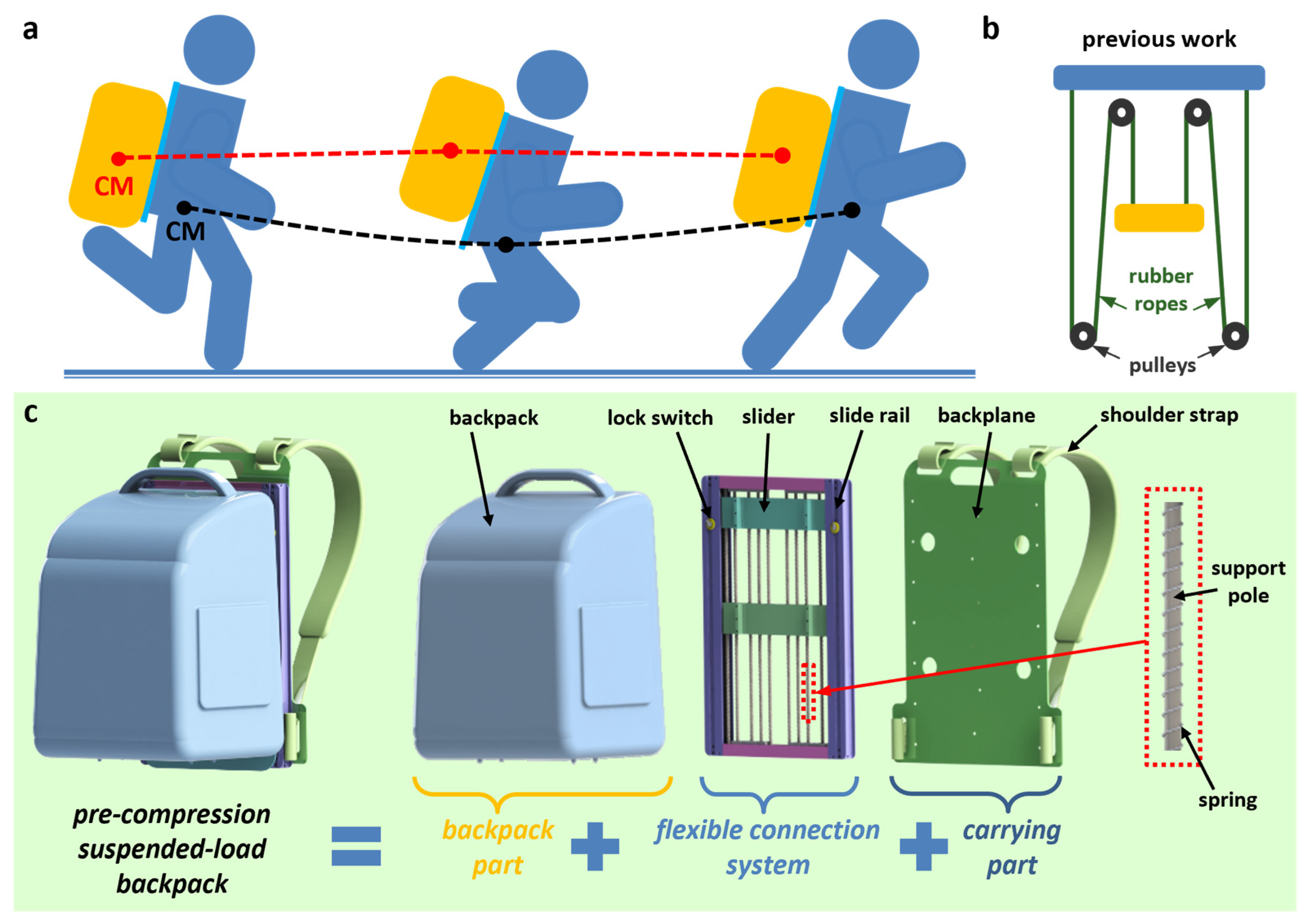
We propose a new design strategy of pre-compression, using pre-compression springs as the elastic components of the SUSB. Previous researchers used pulleys and rubber ropes as the elastic components. Compared with previous studies, the use of pre-compression springs as elastic elements improves the reliability of the SUSB structure, avoids the inconvenience of nonlinearity and material aging, and adds the ability to flexibly adjust the sliding distance of the backpack.
ii.
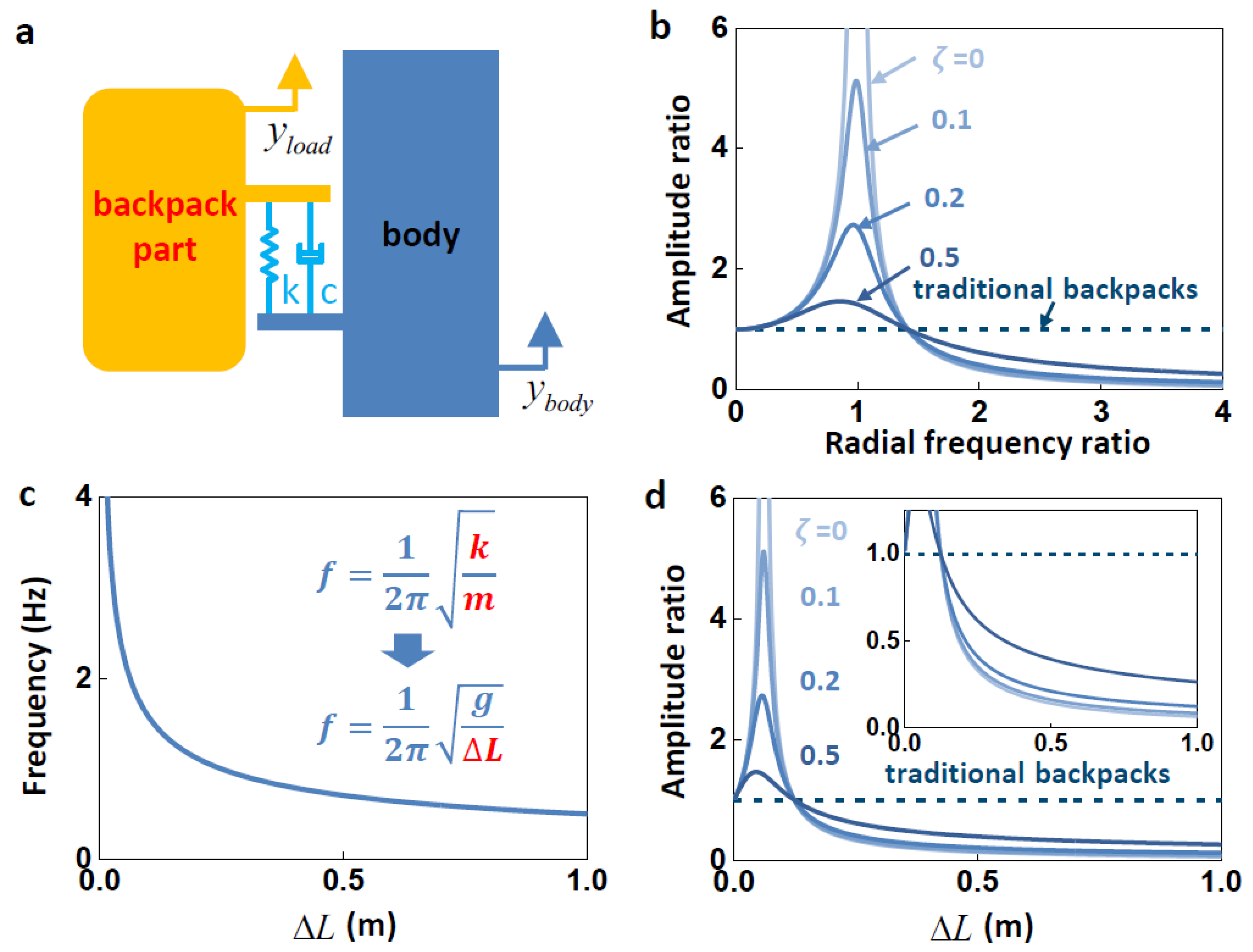
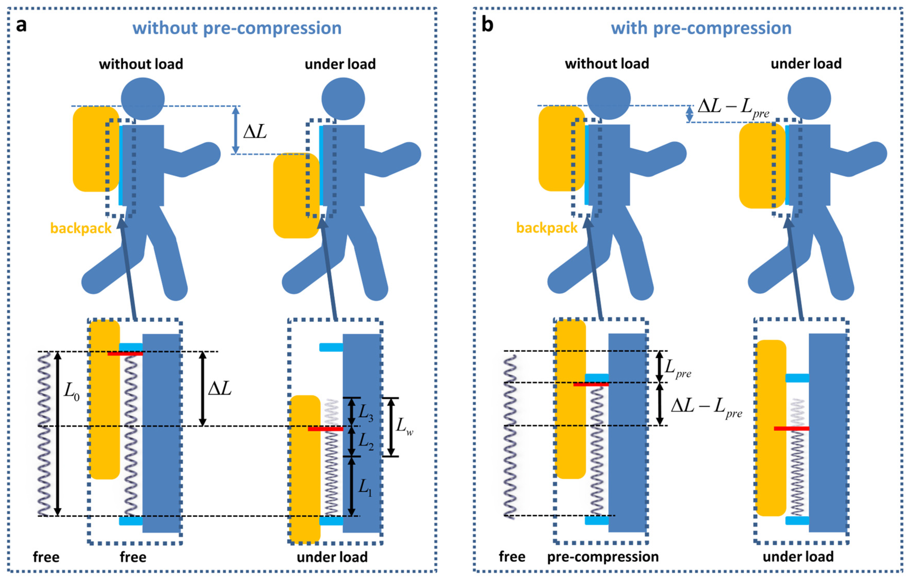
A theoretical model is developed for the pre-compression SUSB. The natural frequency of the pre-compression SUSB is related to only one parameter, the compression amount ΔL. This simplifies the process of evaluating the performance of the pre-compression SUSB.
iii.
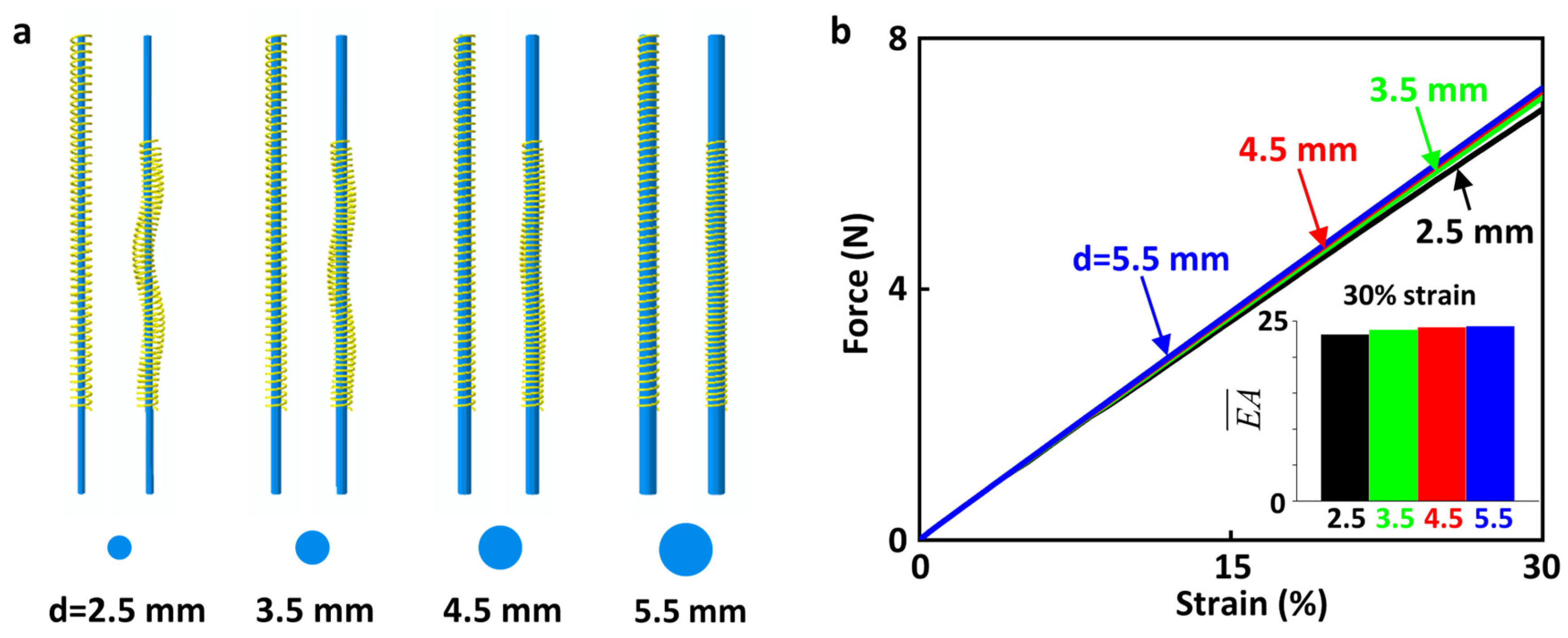
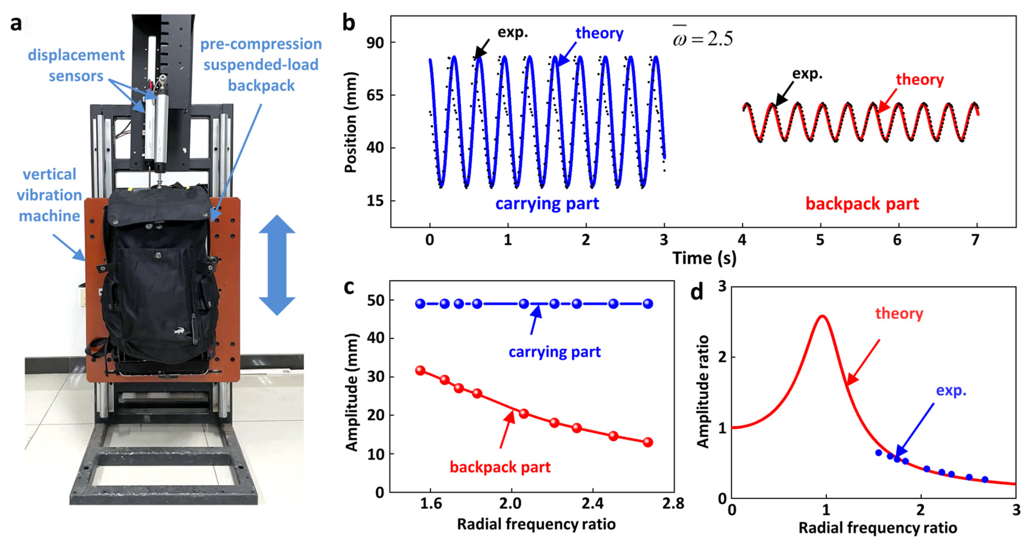
We manufacture the pre-compression SUSB. The suspension performance of the pre-compression SUSB is verified with experiments. At a radial frequency ratio of 2.5, the amplitude of the backpack part is only 30.6% of that of the carrying part. The effect of the buckling behavior of the compression spring on the suspension effect is investigated by FEA. The diameter of the support pole has little effect on the compression stiffness of the spring.
iv.
Previous work added a sliding TENG to the rubber-rope-based SUSB. Because this TENG scavenges energy via the relative movement between the carrying part and the backpack part, the TENG is universal to all SUSBs. In addition to the universal TENG, our SUSB can be equipped with a TENG in the elastic component, which scavenges energy via the relative movement between the elastic components. This work provides a new design idea for the SUSB.

Author Contributions

Y.Y. and Y.S. supervised the research and conceived the idea. M.Z., L.G., J.H. and X.W. carried out the device fabrication and the performance measurement. M.Z. and Y.S. analyzed the data and co-wrote the manuscript. All authors have read and agreed to the published version of the manuscript.

Funding

Y.S. gratefully acknowledges the support of the National Natural Science Foundation of China (No. 12172359), Beijing Municipal Science and Technology Commission (Z191100002019010), Beijing Municipal Natural Science Foundation (No. 2202066), Key Research Program of Frontier Sciences of the Chinese Academy of Sciences (ZDBS-LY-JSC014) and CAS Interdisciplinary Innovation Team (JCTD-2020-03).

Data Availability Statement

The data presented in this study are available on request from the corresponding author. The data are not publicly available due to privacy.

Conflicts of Interest

J.H., X.W. and Y.Y. declare that they have no financial interests. Y.S. and L.G. are cofounders and/or employees of Zhongke Carrying Equipment Technology Co., Ltd., a company that pursues the commercialization of carrying equipment. M.Z., Y.S. and L.G. have two patents (CN201910490794.7; CN201920850886.7) related to this work.

References

  1. Ceylan, E.; Dede, S.; Deger, Y.; Yoruk, I. Investigation of the Effects of Carrying Heavy Load on Prooxidation/Antioxidant Status and Vitamin D3 in Healthy Horses. Asian J. Anim. Vet. Adv. 2008, 4, 41–46. [Google Scholar]
  2. Forkenbrock, D.J. Comparison of external costs of rail and truck freight transportation. Transp. Res. Part A Policy Pract. 2001, 35, 321–337. [Google Scholar]
  3. Forkenbrock, D.J. External costs of intercity truck freight transportation. Transp. Res. Part A-Policy Pract. 1999, 33, 505–526. [Google Scholar]
  4. Woolley-Meza, O.; Thiemann, C.; Grady, D.; Lee, J.J.; Seebens, H.; Blasius, B.; Brockmann, D. Complexity in human transportation networks: A comparative analysis of worldwide air transportation and global cargo-ship movements. Eur. Phys. J. B 2011, 84, 589–600. [Google Scholar]
  5. Kanafani, A. Aircraft technology and network structure in short-haul air transportation. Transp. Res. Part A Gen. 1981, 15, 305–331. [Google Scholar]
  6. Knapik, J.J.; Reynolds, K.L.; Harman, E. Soldier load carriage: Historical, physiological, biomechanical, and medical aspects. Mil. Med. 2004, 169, 45–56. [Google Scholar]
  7. Ren, L.; Jones, R.K.; Howard, D. Dynamic analysis of load carriage biomechanics during level walking. J. Biomech. 2005, 38, 853–863. [Google Scholar]
  8. Balogun, J.A. Ergonomic Comparison of 3 Modes of Load Carriage. Int. Arch. Occup. Environ. Health 1986, 58, 35–46. [Google Scholar]
  9. Ramanathan, N.L.; Datta, S.R.; Gupta, M.N. Biomechanics of various modes of load transport on level ground. Indian J. Med. Res. 1972, 60, 1702–1710. [Google Scholar]
  10. Kim, J.; Lee, G.; Heimgartner, R.; Revi, D.A.; Karavas, N.; Nathanson, D.; Galiana, I.; Eckert-Erdheim, A.; Murphy, P.; Perry, D.; et al. Reducing the metabolic rate of walking and running with a versatile, portable exosuit. Science 2019, 365, 668–672. [Google Scholar]
  11. Zoss, A.; Kazerooni, H. Design of an electrically actuated lower extremity exoskeleton. Adv. Robot. 2006, 20, 967–988. [Google Scholar]
  12. Guizzo, E.; Goldstein, H. The rise of the body bots. IEEE Spectr. 2005, 42, 50–56. [Google Scholar] [CrossRef]
  13. Fontana, M.; Vertechy, R.; Marcheschi, S.; Salsedo, F.; Bergamasco, M. The Body Extender: A Full-Body Exoskeleton for the Transport and Handling of Heavy Loads. IEEE Robot. Autom. Mag. 2014, 21, 34–44. [Google Scholar]
  14. Collins, S.H.; Wiggin, M.B.; Sawicki, G.S. Reducing the energy cost of human walking using an unpowered exoskeleton. Nature 2015, 522, 212–215. [Google Scholar] [PubMed]
  15. Zhang, J.; Fiers, P.; Witte, K.A.; Jackson, R.W.; Poggensee, K.L.; Atkeson, C.G.; Collins, S.H. Human-in-the-loop optimization of exoskeleton assistance during walking. Science 2017, 356, 1280–1284. [Google Scholar] [PubMed]
  16. Nasiri, R.; Ahmadi, A.; Ahmadabadi, M.N. Reducing the Energy Cost of Human Running Using an Unpowered Exoskeleton. IEEE Trans. Neural Syst. Rehabil. Eng. 2018, 26, 2026–2032. [Google Scholar]
  17. Abohamer, M.K.; Awrejcewicz, J.; Amer, T.S. Modeling and analysis of a piezoelectric transducer embedded in a nonlinear damped dynamical system. Nonlinear Dyn. 2023, 111, 8217–8234. [Google Scholar]
  18. Wang, X.; Liu, X.; Zhang, J.; Liang, L.; Li, M.; Yao, H.; Hou, T.; Wu, Y.; Zi, Y.; Zheng, H. A high-applicability, high-durability wearable hybrid nanogenerator with magnetic suspension structure toward health monitoring applications. Nano Energy 2022, 103, 107774. [Google Scholar]
  19. Wang, K.; Wu, C.; Zhang, H.; Li, J.; Li, J. Cylindrical bearing inspired oil enhanced rolling friction based nanogenerator. Nano Energy 2022, 99, 107372. [Google Scholar]
  20. Abohamer, M.K.; Awrejcewicz, J.; Starosta, R.; Amer, T.S.; Bek, M.A. Influence of the Motion of a Spring Pendulum on Energy-Harvesting Devices. Appl. Sci. 2021, 11, 8658. [Google Scholar]
  21. Abohamer, M.; Awrejcewicz, J.; Amer, T. Modeling of the vibration and stability of a dynamical system coupled with an energy harvesting device. Alex. Eng. J. 2023, 63, 377–397. [Google Scholar] [CrossRef]
  22. Xiao, X.; Nashalian, A.; Libanori, A.; Fang, Y.; Li, X.; Chen, J. Triboelectric Nanogenerators for Self-Powered Wound Healing. Adv. Health Mater. 2021, 10, 2100975. [Google Scholar] [CrossRef] [PubMed]
  23. Choi, D.; Lee, Y.; Lin, Z.-H.; Cho, S.; Kim, M.; Ao, C.K.; Soh, S.; Sohn, C.; Jeong, C.K.; Lee, J.; et al. Recent Advances in Triboelectric Nanogenerators: From Technological Progress to Commercial Applications. ACS Nano 2023, 17, 11087–11219. [Google Scholar] [CrossRef] [PubMed]
  24. Barman, S.R.; Chan, S.-W.; Kao, F.-C.; Ho, H.-Y.; Khan, I.; Pal, A.; Huang, C.-C.; Lin, Z.-H. A self-powered multifunctional dressing for active infection prevention and accelerated wound healing. Sci. Adv. 2023, 9, eadc8758. [Google Scholar] [CrossRef] [PubMed]
  25. Zhao, H.; Xu, M.; Shu, M.; An, J.; Ding, W.; Liu, X.; Wang, S.; Zhao, C.; Yu, H.; Wang, H.; et al. Underwater wireless communication via TENG-generated Maxwell’s displacement current. Nat. Commun. 2022, 13, 3325. [Google Scholar] [CrossRef] [PubMed]
  26. Lu, Y.; Jiang, L.L.; Yu, Y.; Wang, D.H.; Sun, W.T.; Liu, Y.; Yu, J.; Zhang, J.; Wang, K.; Hu, H.; et al. Liquid-liquid triboelectric nanogenerator based on the immiscible interface of an aqueous two-phase system. Nat. Commun. 2022, 13, 5316. [Google Scholar] [CrossRef]
  27. Long, L.; Liu, W.; Wang, Z.; He, W.; Li, G.; Tang, Q.; Guo, H.; Pu, X.; Liu, Y.; Hu, C. High performance floating self-excited sliding triboelectric nanogenerator for micro mechanical energy harvesting. Nat. Commun. 2021, 12, 4689. [Google Scholar] [CrossRef]
  28. Li, C.; Liu, D.; Xu, C.; Wang, Z.; Shu, S.; Sun, Z.; Tang, W.; Wang, Z.L. Sensing of joint and spinal bending or stretching via a retractable and wearable badge reel. Nat. Commun. 2021, 12, 2950. [Google Scholar] [CrossRef]
  29. Ye, C.Y.; Liu, D.; Chen, P.F.; Cao, L.N.Y.; Li, X.J.; Jiang, T.; Wang, Z.L. An Integrated Solar Panel with a Triboelectric Nanogenerator Array for Synergistic Harvesting of Raindrop and Solar Energy. Adv. Mater. 2023, 35, 2209713. [Google Scholar] [CrossRef]
  30. Gard, A.S.; Miff, S.C.; Kuo, A.D. Comparison of kinematic and kinetic methods for computing the vertical motion of the body center of mass during walking. Hum. Mov. Sci. 2004, 22, 597–610. [Google Scholar] [CrossRef]
  31. Kram, R. Carrying Loads with Springy Poles. J. Appl. Physiol. 1991, 71, 1119–1122. [Google Scholar] [CrossRef]
  32. Rome, L.C.; Flynn, L.; Yoo, T.D. Rubber bands reduce the cost of carrying loads. Nature 2006, 444, 1023–1024. [Google Scholar] [CrossRef]
  33. Hoover, J.; Meguid, S.A. Performance assessment of the suspended-load backpack. Int. J. Mech. Mater. Des. 2011, 7, 111–121. [Google Scholar] [CrossRef]
  34. Li, D.; Li, T.; Li, Q.; Liu, T.; Yi, J. A simple model for predicting walking energetics with elastically-suspended backpack. J. Biomech. 2016, 49, 4150–4153. [Google Scholar] [CrossRef]
  35. Ackerman, J.; Seipel, J. A model of human walking energetics with an elastically-suspended load. J. Biomech. 2014, 47, 1922–1927. [Google Scholar] [CrossRef] [PubMed]
  36. Yang, Z.; Yang, Y.; Liu, F.; Wang, Z.; Li, Y.; Qiu, J.; Xiao, X.; Li, Z.; Lu, Y.; Ji, L.; et al. Power Backpack for Energy Harvesting and Reduced Load Impact. ACS Nano 2021, 15, 2611–2623. [Google Scholar] [CrossRef]
  37. Foissac, M.; Millet, G.Y.; Geyssant, A.; Freychat, P.; Belli, A. Characterization of the mechanical properties of backpacks and their influence on the energetics of walking. J. Biomech. 2009, 42, 125–130. [Google Scholar] [CrossRef] [PubMed]
  38. Harandi, M.H.F.; Loghmani, A.; Attarilar, S. Backpack with a nonlinear suspension system designed for low walking speeds. Arch. Appl. Mech. 2023, 93, 2465–2481. [Google Scholar] [CrossRef]
  39. Yang, Z.; Huang, L.; Zeng, Z.; Wang, R.; Hu, R.; Xie, L. Evaluation of the Load Reduction Performance Via a Suspended Backpack With Adjustable Stiffness. J. Biomech. Eng. 2021, 144, 051001. [Google Scholar] [CrossRef]
  40. Fan, K.; Xia, P.; Li, R.; Guo, J.; Tan, Q.; Wei, D. An innovative energy harvesting backpack strategy through a flexible mechanical motion rectifier. Energy Convers. Manag. 2022, 264, 115731. [Google Scholar] [CrossRef]
  41. Yoshimura, N.; Kumagai, S.; Nishimura, S. Electrical and environmental aging of silicone rubber used in outdoor insulation. IEEE Trans. Dielectr. Electr. Insul. 1999, 6, 632–650. [Google Scholar] [CrossRef]
  42. Gorur, R.S.; Karady, G.G.; Jagota, A.; Shah, M.; Yates, A.M.; Schneider, H.M.; Detourreil, C.; Mackevich, J.P.; Hoffman, J.W.; Orbeck, T.; et al. Aging in Silicone-Rubber Used for outdoor Insulation. IEEE Trans. Power Deliv. 1992, 7, 525–538. [Google Scholar] [CrossRef]
  43. Chaudhry, A.; Billingham, N. Characterisation and oxidative degradation of a room-temperature vulcanised poly(dimethylsiloxane) rubber. Polym. Degrad. Stab. 2001, 73, 505–510. [Google Scholar] [CrossRef]
Figure 1. Schematic illustration of the pre-compression SUSB. (a) Schematic illustration of a running man with an SUSB. (b) Design of elastic components in previous work. (c) The overall schematic and the magnified schematic of the pre-compression SUSB.
Nanoenergyadv 03 00014 g001
Figure 2. The benefits of the pre-compression design. Comparison of springs (a) without and (b) with pre-compression.
Nanoenergyadv 03 00014 g002
Figure 3. Theoretical study of the pre-compression SUSB. (a) The model to represent the pre-compression SUSB. (b) The relationship between the amplitude ratio and radial frequency ratio under different damping. (c) The relationship between the frequency and Δ L . (d) The relationship between the amplitude ratio and Δ L under different damping.
Nanoenergyadv 03 00014 g003
Figure 4. Experimental and theoretical study of the pre-compression SUSB. (a) Physical illustration of the pre-compression SUSB in the experiment. (b) Theoretical (solid line) and experimental (scatter) diagrams of the displacement of the carrying part and backpack part at the radial frequency ratio of 2.5. (c) Amplitude of the carrying part and backpack part at different radial frequency ratios. (d) The theoretical relationship between the amplitude ratio and the radial frequency ratio achieved by fitting the experimental findings.
Nanoenergyadv 03 00014 g004
Figure 5. The effect of support poles of different diameters. (a) FEA results of the springs (yellow) and support poles (blue) under four different diameters. (b) Force–strain curves of the springs under support poles with different diameters.
Nanoenergyadv 03 00014 g005
Disclaimer/Publisher’s Note: The statements, opinions and data contained in all publications are solely those of the individual author(s) and contributor(s) and not of MDPI and/or the editor(s). MDPI and/or the editor(s) disclaim responsibility for any injury to people or property resulting from any ideas, methods, instructions or products referred to in the content.

