Article

Transient Response of an Infinite Isotropic Magneto-Electro-Elastic Material with Multiple Axisymmetric Planar Cracks

Department of Mechanical Engineering, Najafabad Branch, Islamic Azad University, Najafabad 8514143131, Iran
*
Author to whom correspondence should be addressed.
Solids 2025, 6(3), 54; https://doi.org/10.3390/solids6030054
Submission received: 15 January 2024 / Revised: 13 February 2025 / Accepted: 26 February 2025 / Published: 22 September 2025

Abstract

Dynamic behavior of coaxial axisymmetric planar cracks in the transversely isotropic magneto-electro-elastic (MEE) material in transient in-plane magneto-electro-mechanical loading is studied. Magneto-electrically impermeable as well as permeable cracks are assumed for crack surfaces. In the first step, considering prismatic and radial dynamic dislocations, electric and magnetic jumps are obtained through Laplace and Hankel transforms. These solutions are utilized to derive singular integral equations in the Laplace domain for the axisymmetric penny-shaped and annular cracks. Derived Cauchy singular type integral equations are solved to obtain the density of dislocation on the crack surfaces. Dislocation densities are utilized in computation of the dynamic stress intensity factors, electric displacement, and magnetic induction in the vicinity tips of crack tips. Finally, some numerical case studies of single and multiple cracks are presented. The effect of system parameters on the results is then discussed.

1. Introduction

A magneto-electro-elastic (MEE) medium is typically composed of a combination of piezoelectric and piezomagnetic components, often reinforced with layers or fibers.
These materials possess the unique ability to convert electrical energy, magnetism, and elasticity into one another—a property not found in simple piezoelectric materials. In certain cases, the magneto-electrical effect in MEE materials significantly surpasses that of single-phase magneto-electric materials, even when the latter exhibit a high magneto-electro coefficient [1]. Due to these distinctive properties, MEE materials find extensive applications in advanced technologies, including magnetic field probes, medical imaging systems, transducers, sensors, and actuators [2,3,4,5,6,7].
Recent research has increasingly focused on investigating cracks in MEE structures. However, the majority of these studies have primarily addressed static loading conditions [8,9,10,11,12,13,14,15,16]. In practice, MEE materials are often subjected to dynamic loads during their operational cycles. Consequently, understanding the failure mechanisms associated with crack growth under such conditions is a critical design consideration, and this issue has attracted significant attention from researchers.
Several studies have explored the dynamic behavior of cracks in MEE materials. For instance, Li conducted a dynamic analysis of cracks in an MEE medium under mechanical, electrical, and magnetic impulses [17]. Hu and Li developed an analytical approach to study the effect of a moving crack with permeable crack faces in an infinite MEE solid under shear loading [18]. Zhou et al. [19] examined the dynamic behavior of collinear cracks between two dissimilar MEE half-planes subjected to harmonic anti-plane shear waves. Zhang et al. [20] investigated the dynamic response of two collinear interface cracks between dissimilar functionally graded MEE layers. Su et al. [21] analyzed the transient behavior of interface cracks between different MEE strips under out-of-plane mechanical loading and magneto-electrical impacts.
Further contributions to this field include the work of Feng and Pan [22], who studied the dynamic fracture of anti-plane interfacial cracks under combined mechanical and magneto-electrical loadings under various boundary conditions. Liang [23] explored the dynamic behavior of parallel symmetric cracks in functionally graded MEE materials excited by harmonic shear waves. Sladek et al. [24] employed Galerkin’s method to analyze cracks under transient loading in 2D and 3D axisymmetric piezoelectric/piezomagnetic media. Feng et al. [25] investigated the dynamic response of surface cracks between two dissimilar MEE materials under simultaneous magnetic, electrical, and mechanical shock.
Additional studies have focused on specific crack geometries and loading conditions. Zhong and Zhang [26] and Zhong et al. [27] studied the dynamic behavior of an MEE material with a penny-shaped crack under magneto-electro-mechanical impact loading. Feng et al. [28] examined the dynamic response of an MEE penny-shaped cracked layer under in-plane impacts, while Zhong et al. [29] analyzed the response of an MEE solid with a Griffith crack. Wang et al. [30] evaluated the effect of electric and magnetic boundary conditions on the dynamic response of an MEE structure. Li and Lee [31] addressed the issue of collinear dissimilar cracks in MEE materials under mode I loading using dislocation simulations.
Recent theoretical advances in fractional Brownian motion (FBM) have deepened our understanding of nonstationary behaviors in complex systems. For instance, Wang et al. [32] revealed complex dynamics in systems with space-dependent diffusivity, characterized by deviations from normal diffusion typically seen in biological and complex fluid systems. The integration of HDPs and fractional Brownian motion (FBM) offers a framework to understand these dynamics, especially regarding mean-squared displacement (MSD) and ergodicity breaking. This synthesis highlights the key aspects of these phenomena. Thapa et al. [33] investigated Bayesian inference for distinguishing between scaled Brownian motion (sBM) and fractional Brownian motion (fBM). They revealed that the primary challenge arises from the inherent differences between these two stochastic processes in their scaling properties and memory effects. Bayesian approaches provide a robust framework for addressing these challenges by incorporating prior knowledge and updating beliefs based on observed data.
Advanced analytical and numerical methods have also been applied to this field. Wunsche et al. [34] applied boundary element analysis to determine the dynamic response of linear anisotropic MEE materials. Athanasius and Ang [35] proposed a semi-analytic approach using Laplace transforms to study the dynamic response of an MEE full space with multiple arbitrarily oriented planar cracks. Li et al. [36] investigated the dynamic response of a ring-shaped interface crack between distinct magneto-electroelastic materials, while Li et al. [37] studied a ring-shaped crack between a magneto-electroelastic thin film and an elastic substrate under mechanical, electrical, and magnetic stress. Lei et al. [38] analyzed the transient response of an interface crack in MEE bi-materials under magneto-electromechanical loads. Xiao et al. [39] examined the mode III fracture problem of an MEE medium weakened by an alternating array of cracks and rigid inclusions under coupled anti-plane mechanical and in-plane electrical and magnetic stresses.
To the best of the authors’ knowledge, no comprehensive study has yet addressed the transient response of multiple axisymmetric planar cracks in transversely isotropic MEE materials under in-plane magneto-electromechanical loading. Among the available techniques for solving such problems, the dislocation method [40] has proven to be an effective tool for analyzing multiple cracks. This paper aims to determine the generalized dynamic intensity factors for multiple axisymmetric planar cracks in a transversely isotropic MEE medium.
Laplace and Hankel transformations are employed to reduce the problem to Cauchy-type singular integral equations. A numerical Laplace transformation inversion method, as proposed by Stehfest [41,42,43], is then used to formulate the generalized dynamic intensity factors at the crack tips. The dislocation densities are determined to model the multiple axisymmetric planar cracks in the transversely isotropic MEE medium. This study also examines the influence of time variation, applied magneto-electric impact loadings, crack surface boundary conditions, crack type, and crack interactions on the dynamic characteristics of the cracks.
This study investigates the transient response of multiple coaxial axisymmetric planar cracks embedded in a transversely isotropic magneto-electro-elastic (MEE) medium subjected to in-plane magneto-electro-mechanical impact loads. Both magneto-electrically impermeable and permeable crack-face boundary conditions are rigorously analyzed. The distributed dislocation method is employed to formulate the problem, where prismatic and radial dynamic dislocations are incorporated to model the discontinuities in mechanical, electric, and magnetic fields. By leveraging Laplace and Hankel integral transforms, the governing equations are reduced to a system of Cauchy-type singular integral equations in the Laplace domain. These equations are solved numerically to determine the dislocation densities on the crack surfaces, which are subsequently used to compute the dynamic stress intensity factors (DSIFs), electric displacement intensity factors (DEIFs), and magnetic induction intensity factors (DMIFs) at the crack tips. The results demonstrate that impermeable cracks exhibit higher peak DSIFs than permeable ones, while static solutions converge independently of electromagnetic boundary conditions. Additionally, crack spacing and geometry significantly alter the dynamic response, with inner annular crack tips showing elevated intensity factors compared to outer tips. The magneto-electro-mechanical coupling parameter amplifies crack-tip fields, and crack interactions profoundly affect mode-I and mode-II DSIF magnitudes.
This paper is structured as follows: Section 2 derives the governing equations for the transient behavior of the transversely isotropic MEE medium. Section 3 formulates the axisymmetric planar crack problem, incorporating magneto-electro-mechanical coupling effects. Section 4 presents numerical case studies, including (i) a single penny-shaped crack (Section 4.1), (ii) an annular crack (Section 4.2), (iii) two non-planar penny-shaped cracks (Section 4.3), and (iv) a penny-shaped crack surrounded by an annular crack (Section 4.4). These examples systematically explore the influence of crack geometry, electromagnetic boundary conditions, and crack interactions on the dynamic fracture characteristics. Additionally, a section entitled “Validation, Innovations, and Applications” is included in Section 4.5, to provide insights into the novel contributions of this research and its practical implications. Finally, Section 5 summarizes the key findings, emphasizing the transient evolution of generalized intensity factors, the distinct roles of crack-face permeability, and the critical interplay between magneto-electro-mechanical coupling and crack configuration.

2. Derivation of Governing Equations

The problem under study is an infinite transversely isotropic MEE medium with generalized dynamic dislocations. For a transversely isotropic MEE medium with the plane of isotropy perpendicular to the z-axis, the electrical and magnetic poling are assumed parallel to z axis. Assuming planar deformation, the linear constitutive equations for axisymmetric medium can be stated as follows, ( u θ = 0 )
σ r r r , z , t σ θ θ r , z , t σ z z r , z , t D z r , z , t B z r , z , t = c 11 c 12 c 13 e 31 α 31 c 12 c 11 c 13 e 31 α 31 c 13 c 13 c 33 e 33 α 33 e 31 e 31 e 33 d 33 β 33 α 31 α 31 α 33 β 33 γ 33 u r , r r , z , t u r r , z , t / r u z , z r , z , t ψ , z r , z , t ϕ , z r , z , t σ r z r , z , t D r r , z , t B r r , z , t = c 44 c 44 e 15 α 15 e 15 e 15 d 11 β 11 α 15 α 15 β 11 γ 11 u r , z r , z , t u z , r r , z , t ψ , r r , z , t ϕ , r r , z , t ,
The comma states partial differentiation with respect to the suffix space variable and σ i j ,   D i , and B i are stress components, electric displacements, and magnetic inductions, respectively; while e i j ,   α i j and β i j are the piezoelectric, piezomagnetic, and magnetoelectric coupling constants; c i j ,   d i j and γ i j are elastic stiffnesses, dielectric permittivities, and the magnetic permeabilities, respectively; u r and u z are the radial and axial displacement components; ψ and ϕ are electric and magnetic potential, respectively. The equilibrium equations of transversely isotropic MEE media, considering zero body force, free electric charge, and current, are given by [44,45,46]
σ r r , r + σ r z , z + σ r r σ θ θ r = ρ u r , t t σ r z , r + σ z z , z + σ r z r = ρ u z , t t D r , r + D z , z + D r r = 0 B r , r + B z , z + B r / r = 0
where ρ is the mass density. Electric potential, magnetic potential, and elastic displacements satisfy the basic equations as follows:
c 11 L 1 + c 44 D 2 u r + c 13 + c 44 D u z , r + e 31 + e 15 D ψ , r + α 31 + α 15 D ϕ , r = ρ F 2 u r c 44 L 0 + c 33 D 2 u z + c 13 + c 44 D r u r , r / r + e 15 L 0 + e 33 D 2 ψ + α 15 L 0 + α 33 D 2 ϕ = ρ F 2 u z e 15 + e 31 D r u r , r / r + c 15 L 0 + e 33 D 2 u z d 11 L 0 + d 33 D 2 ψ β 11 L 0 + β 33 D 2 ϕ = 0 α 15 + α 31 D r u r , r / r + α 15 L 0 + α 33 D 2 u z β 11 L 0 + β 33 D 2 ψ γ 11 L 0 + γ 33 D 2 ϕ = 0
In which the differential operators are introduced as
L k = 2 r 2 + 1 r r k r 2 ,         k = 0,1 D = z D 2 = 2 z 2 F 2 = 2 t 2
Using the Laplace transforms, the governing equations were converted to the frequency domain. This transformation separates dynamic and static components, establishing a foundation for analyzing penny-shaped cracks. Mathematical details are provided in Appendix A, Appendix B, Appendix C, Appendix D, Appendix E and Appendix F.
For the present problem, two types of magnetoelectrical boundary conditions [47] are assumed by extending the concept of the electrically impermeable and permeable cracks embedded in piezoelectric medium [48]. They are electrically and magnetically impermeable and electrically and magnetically permeable, respectively; the first case is called type-a and the second case is called a type-b solution, respectively. Without loss of generality, the type-a solution is considered. The type-b solution can be obtained by reducing the type-a solution. Let the transversely isotropic MEE medium weakened by a Volterra-type dynamic prismatic ring and Somigliana-type dynamic radial ring dislocations with Burgers vectors b_z (t) and b_r (t), respectively, which are located at r = a and z = 0, wherein the radial cut of dislocations are circular area. The above dislocation conditions can be expressed in Appendix C [49].

3. Axisymmetric Planar Crack Formulation

The distributed dislocation method was utilized by some researchers for the analysis of cracked bodies subjected to mechanical loading, see, e.g., Weertman [48]. The dislocation solutions carried out in the previous section may be used to analyze transversely isotropic MEE medium weakened by multiple axisymmetric planar cracks subjected to transient in-plane loading. Consider a transversely isotropic MEE medium weakened by N 1 annular cracks and N N 1 penny-shaped cracks, while N denotes the number of coaxial-located defects. The inner and outer radiuses of the annular cracks are assumed a j and b j , j = 1,2 , , N 1 .   c j , j = N 1 + 1 , N 1 + 2 , , N is radii of the j-th penny-shaped crack. Equation (5) represents such axisymmetric planar cracks in the parametric form:
r j s = L j s + 0.5 b j + a j , 1 s 1                   f o r   a n n u l a r   c r a c k s r j s = L j 1 s , 1 s 1                                 f o r   p e n n y   s h a p e d   c r a c k s
Noting that,
L j = 0.5 b j a j                             f o r   a n n u l a r   c r a c k s     j = 1,2 , , N 1 c j             f o r   p e n n y   s h a p e d   c r a c k s     j = N 1 + 1 , , N 1 + N 2
Suppose the prismatic, radial, electric, and magnetic dynamic dislocations with unknown densities of b z * q , p , b r * q , p , b ψ * q , p , and b ϕ * q , p , respectively, are distributed on the infinitesimal segment at the surfaces of the j-th concentric crack located at z = z j . Applying the principle of superposition, the components of in-plane traction, electric, and magnetic potentials at a point with coordinates r i s , z i , where 1 s 1 , on the surface of all cracks yields Integral equations for stresses that are presented in Appendix G. The integral kernels Kijkl (Appendix G, Equations (A25)–(A32) are central to modeling crack interactions. These kernels quantify the influence of distributed dislocations on stress and electromagnetic fields, fully capturing the system’s dynamic behavior.
In the transversely isotropic MEE media, the boundary conditions of the stress field and the electric and magnetic displacement at crack tips behave like 1 / r , where r is the distance from the crack tips. Therefore, by choosing that the embedded crack tips are to be singular at q = 1 , the dislocation densities for each type of crack are classified as [49]
b k j * q , l n 2 t n = G k j * q , l n 2 t n 1 q 2                                   f o r   a n n u l a r   c r a c k s b k j * q , l n 2 t n = G k j * q , l n 2 t n 1 t 1 + t             f o r   p e n n y s h a p e d   c r a c k , k = z , r , ψ   a n d   ϕ                
Substituting Equation (7) into Equation (A31) and application of the numerical approach of singular integral equations with Cauchy-type kernel developed by Faal et al. [50] results in G k j * q , l n 2 t n . Using Equation (A29), the inverse Laplace transform of dislocation densities can be expressed as
g k i q , t = l n 2 t n = 1 M v n G k i * q , l n 2 t n , 1 q 1 , i = 1,2 , N , k = z , r , ψ ,   a n d   ϕ
Finally, the modes I and II dynamic stress intensity factors (DSIFs), dynamic electric displacement intensity factors (DEIFs) and dynamic magnetic induction intensity factors (DMIFs) for annular cracks are [51]
K I L j ( t ) K I I L j ( t ) K D L j ( t ) K B L j ( t ) = π L j 2 1 n = 1 4 ϑ 2 n 1 n g z j ( 1 , t ) + 2 n g ψ j ( 1 , t ) + 3 n g ϕ j ( 1 , t ) 1 Λ n = 1 4 ϑ 3 n Λ n g r j ( 1 , t ) 1 n = 1 4 ϑ 4 n 1 n g z j ( 1 , t ) + 2 n g ψ j ( 1 , t ) + 3 n g ϕ j ( 1 , t ) 1 n = 1 4 ϑ 5 n 1 n g z j ( 1 , t ) + 2 n g ψ j ( 1 , t ) + 3 n g ϕ j ( 1 , t ) K I R j ( t ) K I I R j ( t ) K D R j ( t ) K B R j ( t ) = π L j 2 1 n = 1 4 ϑ 2 n 1 n g z j ( 1 , t ) + 2 n g ψ j ( 1 , t ) + 3 n g ϕ j ( 1 , t ) 1 Λ n = 1 4 ϑ 3 n Λ n g r j ( 1 , t ) 1 n = 1 4 ϑ 4 n 1 n g z j ( 1 , t ) + 2 n g ψ j ( 1 , t ) + 3 n g ϕ j ( 1 , t ) 1 n = 1 4 ϑ 5 n 1 n g z j ( 1 , t ) + 2 n g ψ j ( 1 , t ) + 3 n g ϕ j ( 1 , t )
where L and R in Equation (9) indicate inner and outer tips of annular crack, respectively. Moreover, DSIFs, DEIFs, and DMIFs for a penny-shaped crack are
K I j ( t ) K I I j ( t ) K D j ( t ) K B j ( t ) = π L j 1 n = 1 4 ϑ 2 n 1 n g z j ( 1 , t ) + 2 n g ψ j ( 1 , t ) + 3 n g ϕ j ( 1 , t ) 1 Λ n = 1 4 ϑ 3 n Λ n g r j ( 1 , t ) 1 n = 1 4 ϑ 4 n 1 n g z j ( 1 , t ) + 2 n g ψ j ( 1 , t ) + 3 n g ϕ j ( 1 , t ) 1 n = 1 4 ϑ 5 n 1 n g z j ( 1 , t ) + 2 n g ψ j ( 1 , t ) + 3 n g ϕ j ( 1 , t )
In the case of a crack problem with permeable condition (type-b solution), the electric and magnetic potentials are continuous in the crack positions. Therefore, it is enough to let the jump in electric and magnetic potential be zero, i.e., b ϕ and b ϕ in the boundary conditions (A11) and (A12). The same process as for impermeable cracks is followed to achieve permeable cracks
K I L j ( t ) K I I L j t K I R j ( t ) K I I R j ( t ) = π L j 2 1 n = 1 4 ϑ 2 n 1 n g z j ( 1 , t ) 1 Λ n = 1 4 ϑ 3 n Λ n g r j 1 , t 1 n = 1 4 ϑ 2 n 1 n g z j ( 1 , t ) 1 Λ n = 1 4 ϑ 3 n Λ n g r j ( 1 , t )
for the DSIFs of annular cracks and
K I j ( t ) K I I j ( t ) = π L j 1 n = 1 4 ϑ 2 n 1 n g z j ( 1 , t ) 1 Λ n = 1 4 ϑ 3 n Λ n g r j ( 1 , t )
for penny-shaped cracks. Additionally, the DEIFs and DMIFs are related to the DSIFs through
K D j ( t ) K B j ( t ) = n = 1 4 ϑ 4 n 1 n n = 1 4 ϑ 2 n 1 n K I j t n = 1 4 ϑ 5 n 1 n n = 1 4 ϑ 2 n 1 n K I j ( t )
It is observed that for the permeable condition case, the DSIFs, DEIFs, and DMIFs of a collection of multiple cracks do not depend on the electric and magnetic loadings. This property of generalized intensity coefficients for permeable cracks in transversely isotropic MEE materials has been reported in the literature for a single crack [52] as well as for three parallel asymmetric cracks [53].

4. Numerical Examples

The methodology introduced in the preceding section based on generalized distributed dislocation technique, allowed the consideration of a transversely isotropic MEE medium weakened by multiple axisymmetric planar cracks under transient in-plane magneto-electromechanical loading. The analysis covers both penny-shaped and annular cracks, as shown in Figure 1. The BaTiO3–CoFe2O4 composite material is used in numerical calculations. The piezoelectric and piezomagnetic characteristics of bimaterial composite are taken from the reference [54] and presented in Table 1. In all cases, the medium is subjected to far-field uniform dynamic traction σ z z = σ 0 H ( t ) , dynamic axial electric displacement D z = D 0 H ( t ) , and dynamic axial magnetic induction B z = B 0 H ( t ) , in which σ 0 , D 0 , and, B 0 are the amplitudes of the normal stress, electric displacement, and magnetic induction exerted on crack surfaces, respectively, and H ( . ) is the Heaviside unit step function. The electro-mechanical and magneto-mechanical coupling factors are defined by λ D = D 0 e 15 / σ 0 d 11 and λ B = B 0 α 15 / σ 0 γ 11 to integrate the normal traction σ 0 , electric D 0 , and magnet B 0 loading. In the following examples, for penny-shaped cracks, the modes I and II DSIFs, DEIFs, and DMIFs are normalized by K I 0 = 2 σ 0 l / π , K I I 0 = 2 σ 0 l / π , K D 0 = K I 0 d 11 / e 15 , and K B 0 = K I 0 γ 11 / α 15 , respectively. Additionally, for annular cracks, the generalized dynamic intensity factors are normalized by dividing to K I 0 = σ 0 π l , K I I 0 = σ 0 π l , K D 0 = K I 0 d 11 / e 15 , and K B 0 = K I 0 γ 11 / α 15 , where l is crack length. The results are presented according to normalized time C T t / l , where C T = μ 0 / ρ 0 with μ 0 = c 44 + d 11 α 15 2 2 e 15 α 15 β 11 + γ 11 e 15 2 γ 11 d 11 β 11 2 being the “extended” shear wave velocity in the transversely isotropic MEE medium.

4.1. A Transversely Isotropic MEE Medium with a Penny-Shaped Crack

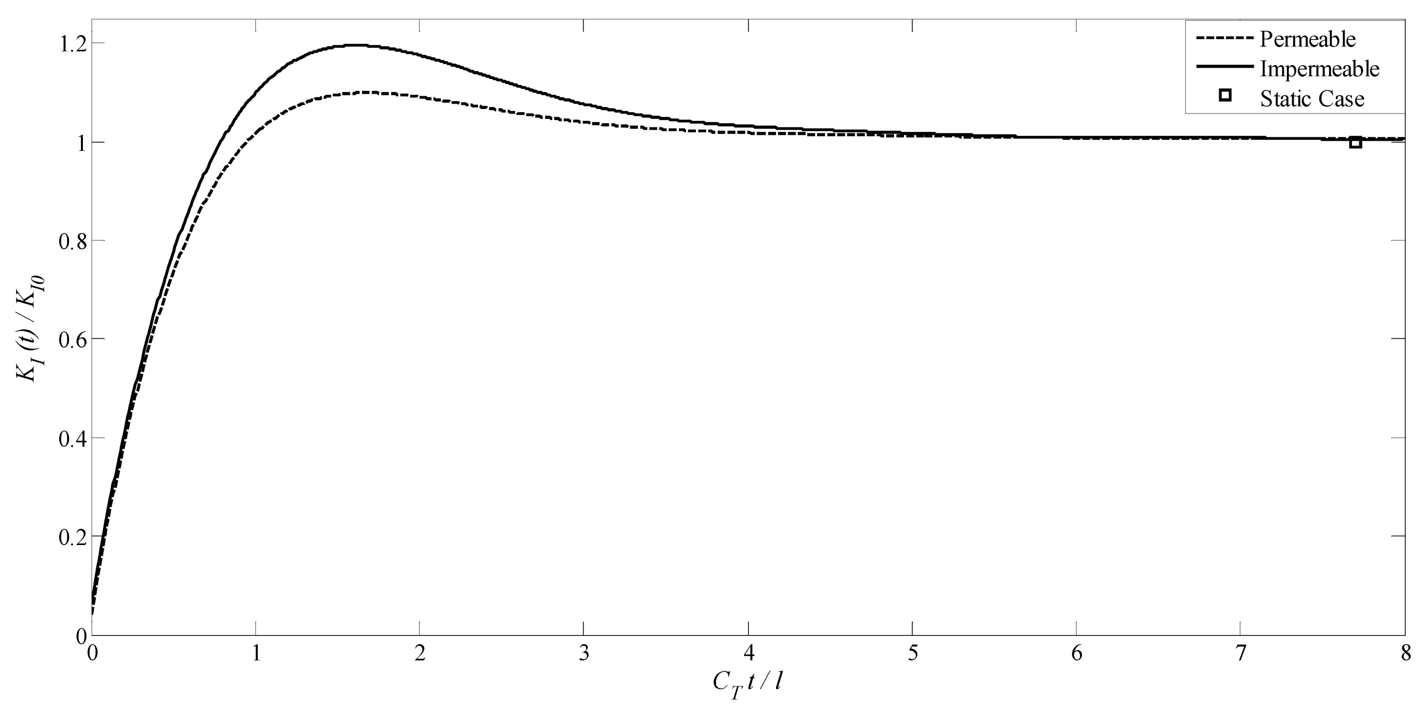
For first example, the problem of a transversely isotropic MEE medium including a penny-shaped crack with radius l = c 1 is investigated. It is assumed that the crack is located at z = 0 . The variations of normalized mode I DSIFs versus C T t / l for magnetoelectrically impermeable and permeable penny-shaped crack with loading combination parameters λ D = 1 and λ B = 1 are depicted in Figure 2. This figure indicates that, regardless of magnetoelectrically impermeable and permeable boundary conditions of the crack surface, by increase of C T t / l the normalized DSIFs first increase to high values and then asymptotically tend to static value. However, the maximum values related to the electromagnetically impermeable crack surface are higher than the values related to the permeable crack. Furthermore, the occurring time the peak values of mode I DSIFs for two types of the impermeable and permeable penny-shaped cracks is similar and appears at about the normalized time C T t / l 1.65 .
Dynamic stress intensity factors (DSIFs) for electromagnetically impermeable cracks significantly exceed those of permeable cracks (Figure 2). This disparity arises from restricted electric/magnetic fields at impermeable crack surfaces, amplifying stress concentration.
In other words, elevated DSIFs for impermeable cracks observed for electromagnetically impermeable cracks stem from the restricted electric and magnetic fluxes. This constraint intensifies stress concentration, as electromagnetic fields cannot permeate the crack region, leading to greater energy accumulation at the crack tip. In contrast, permeable cracks exhibit more uniform field distributions, resulting in reduced stress levels.
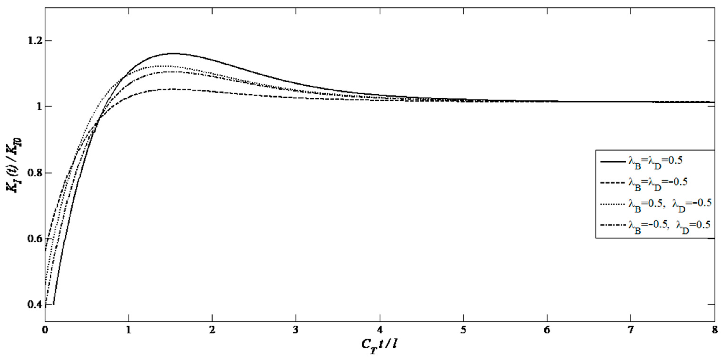
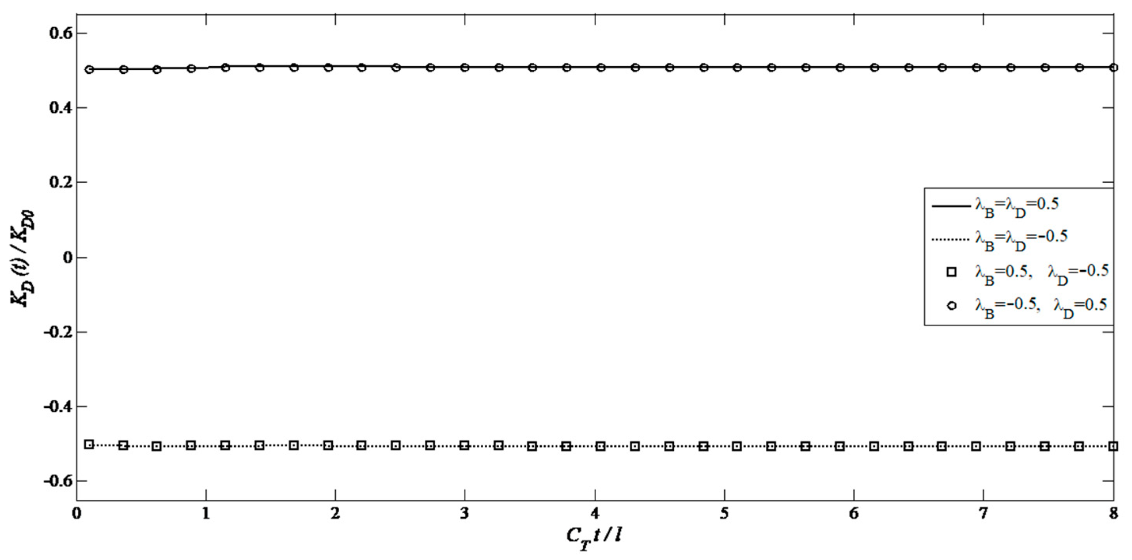
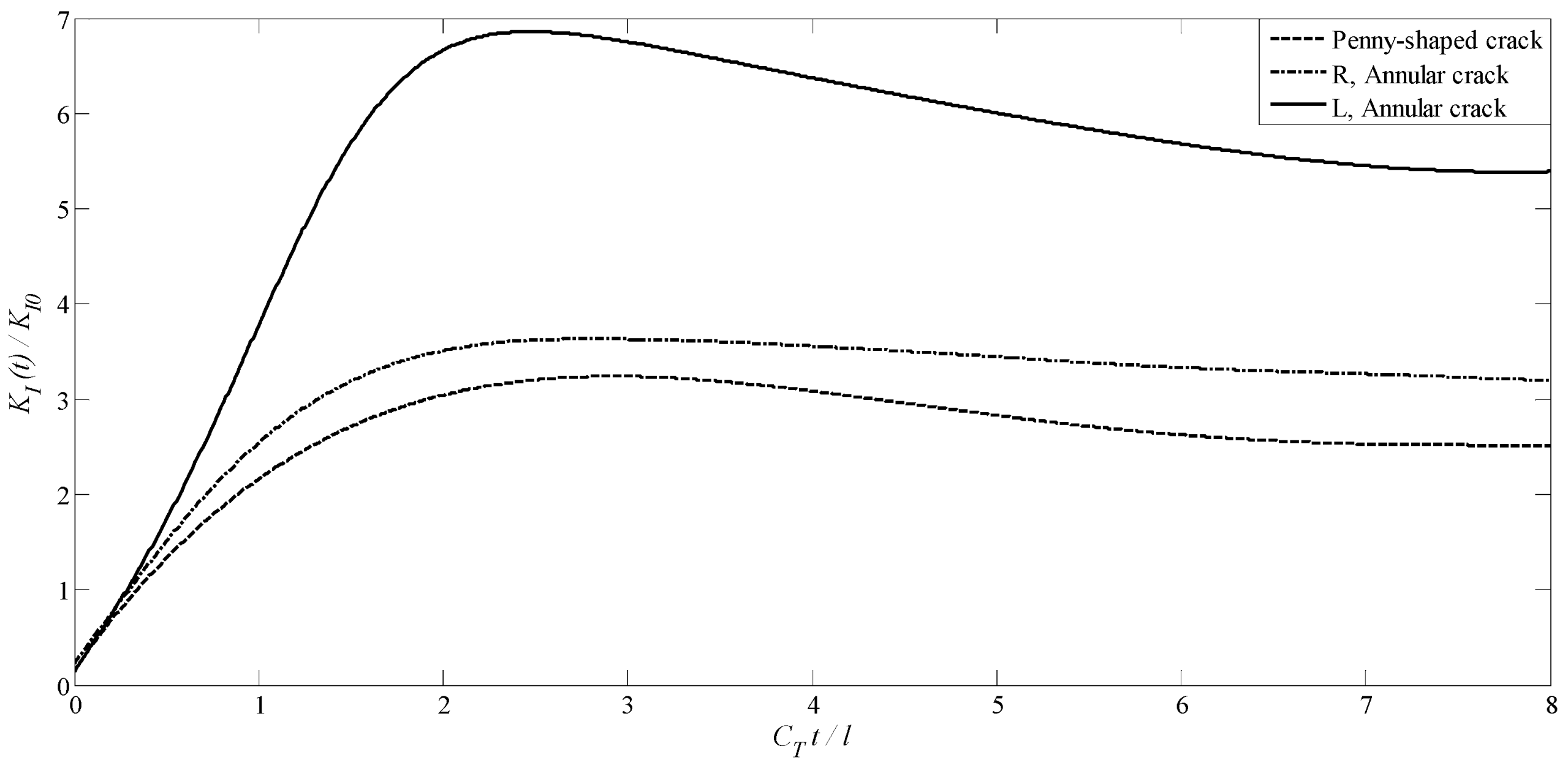
Figure 3, Figure 4 and Figure 5 display the variations of normalized generalized dynamic intensity factors versus normalized time for magnetoelectrically impermeable penny-shaped cracks under different values of combined magneto-electro-mechanical coupling factors. As it might be observed from Figure 3, both the magnetic and electrical loadings significantly affect the DSIFs of mode-I, so that the magnitudes of DSIFs of the crack increase with increasing values of λ D and λ B . Moreover, Figure 4 and Figure 5 indicate that both the DEIFs and DMIFs are almost constant over the normalized time, that electrical loadings do not have considerable effects on the DMIFs, and that magnetic loadings do not have considerable effects on the DEIFs as well.

4.2. A Transversely Isotropic MEE Medium with an Annular Crack

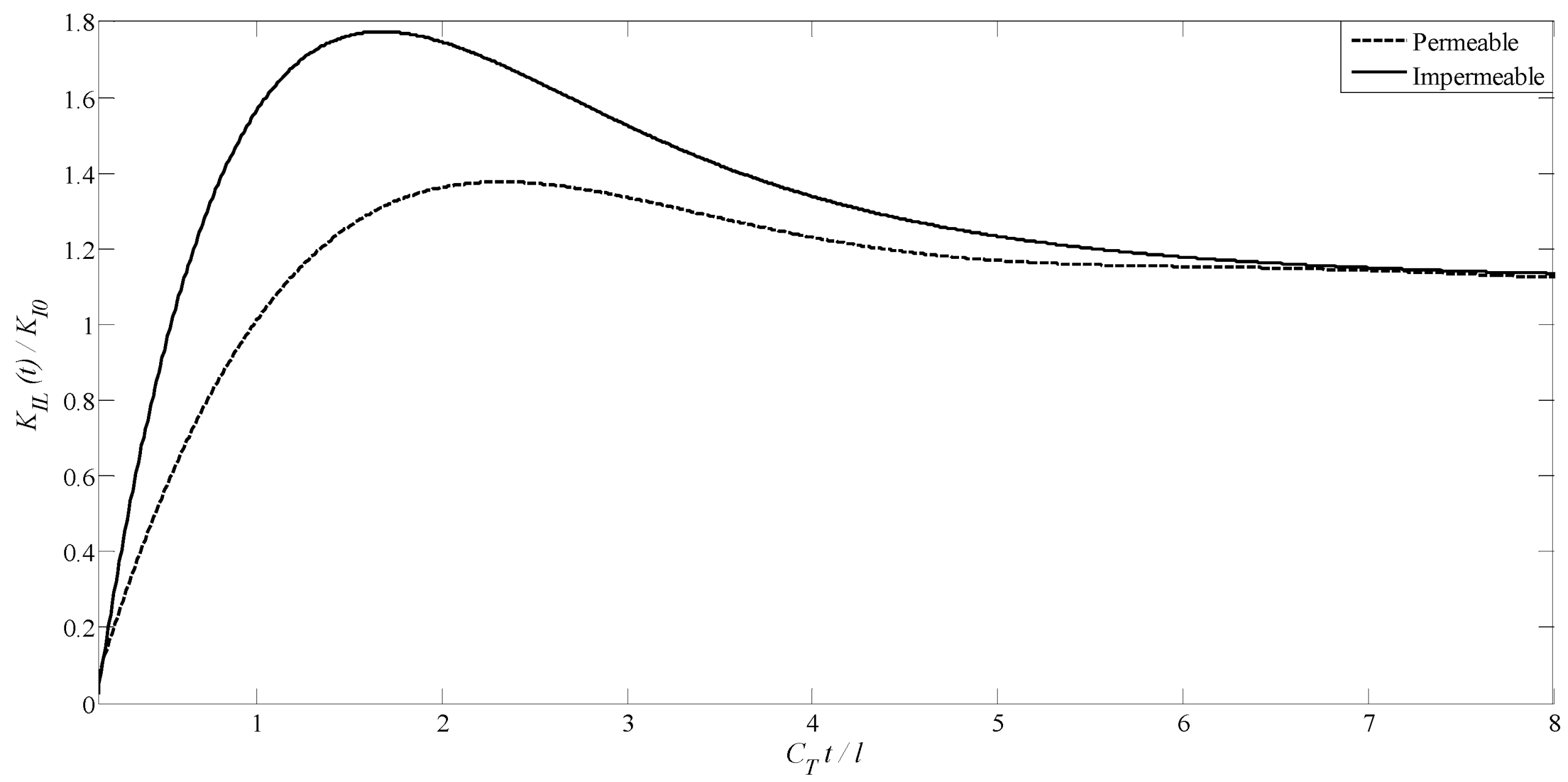
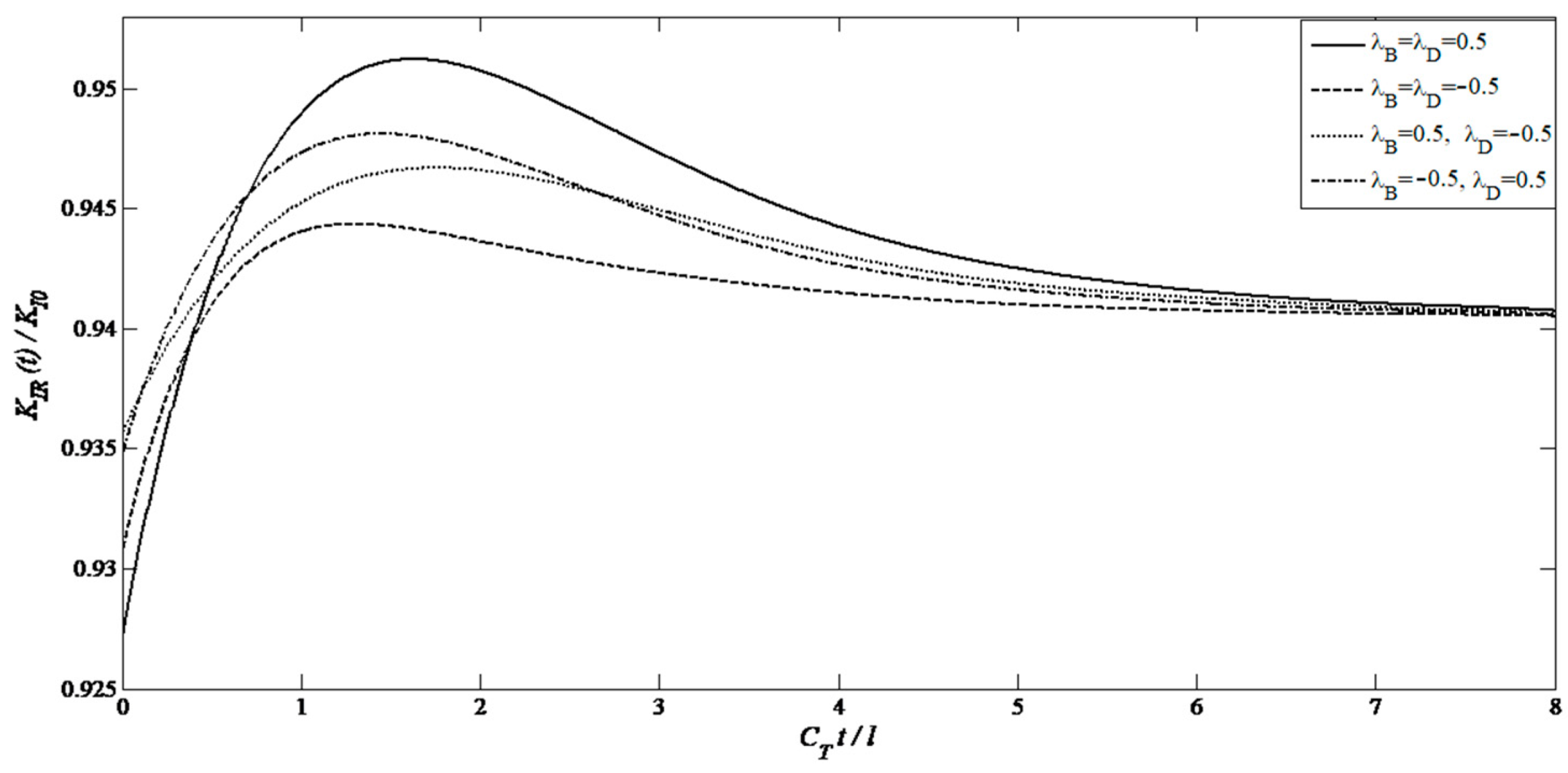
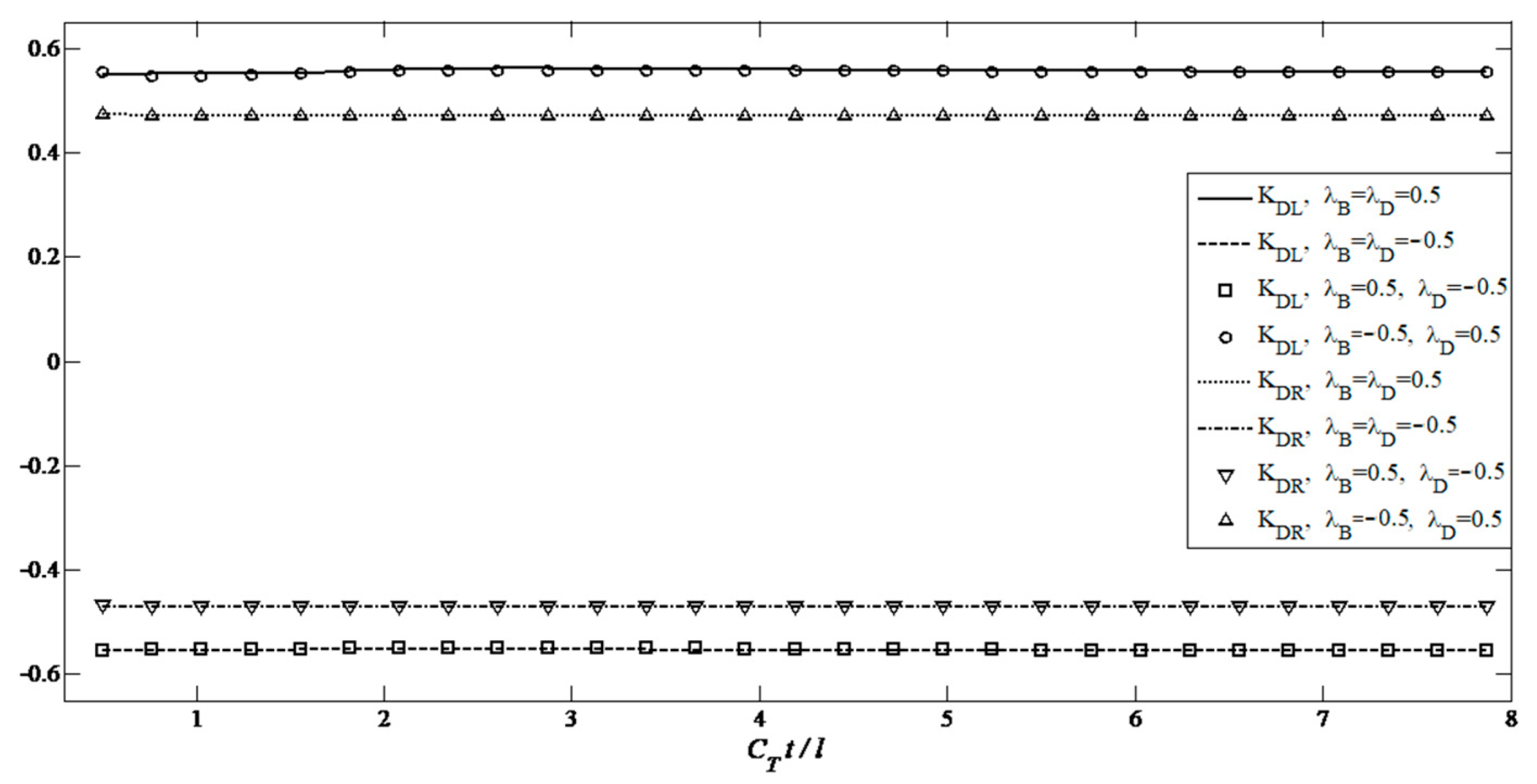
In this example, a transversely isotropic MEE medium weakened by an annular crack with length 2 l = b 1 a 1 is considered. a 1 and b 1 are the inner and outer radii of the annular crack. The crack is assumed to be on the plane z = 0 . For λ D = 1 and λ B = 1 , the non-dimensionalized mode I DSIFs for electrically and magnetically impermeable annular crack are compared with the corresponding DSIFs for electrically and magnetically permeable annular cracks in Figure 6 and Figure 7. As expected, regardless of permeability of the crack, the curves of K I L ( t ) / K I 0 and K I R ( t ) / K I 0 exhibit the transient characteristic. So, for inner and outer tips of annular crack, the DSIFs had a main peak value at about C T t / l = 1.65 for the impermeable condition and C T t / l = 2.1 for the permeable condition. Afterwards, those values decline gradually to the static values. Moreover, for the annular crack, similar to the penny-shaped crack, when t , the curves of modes I DSIFs around both the inner and outer crack tip tend to two constant values, respectively. It reveals that permeability has no significant effect on the stress intensity factors in the static state. Additionally, the modes I DSIFs for inner tips are larger than the outer tips in the case of annular crack.
Figure 6 and Figure 7 depict the effect of the dimensionless time on the behavior of the annular crack tips for different values of electromechanical and magnetomechanical coupling factors. It is easily seen from the figures that the magneto-electromechanical coupling factors have considerable effect on the DSIFs of mode I. So, the peak value of DSIFs for greater magneto-electromechanical coupling factors is much more than the small value. Meanwhile, like the penny-shaped crack, the DEIFs and DMIFs for tips of annular crack are almost independent of the normalized time, and do not depend on magnetic and electrical loadings, respectively.
The higher peak of DSIFs at the inner tip (KIL) versus the outer tip (KIR) of annular cracks (Figure 6) stems from stress heterogeneity inherent to annular geometries.
Similarly, the disparity in DSIF values between the inner and outer tips of annular cracks in Figure 7 arises from the inherent stress heterogeneity in annular geometries. The smaller radius of the inner tip induces higher stress concentration, while the outer tip is influenced by far-field effects. This phenomenon aligns with classical theories of annular cracks in isotropic materials, as demonstrated in studies such as Refs. [55,56,57].
Figure 8 shows the variations of the dimensionless KIL with respect to dimensionless time for different values of the mechanical-electrical and mechanical-magnetic load combination parameters.
The effect of dimensionless time on the behavior of annular crack tips for different values of the mechanical, magnetic, and electrical load combination parameters (λD, λB) is shown in the Figure 9, Figure 10 and Figure 11.

4.3. A Transversely Isotropic MEE Medium with Two Non-Planar Penny-Shaped Cracks

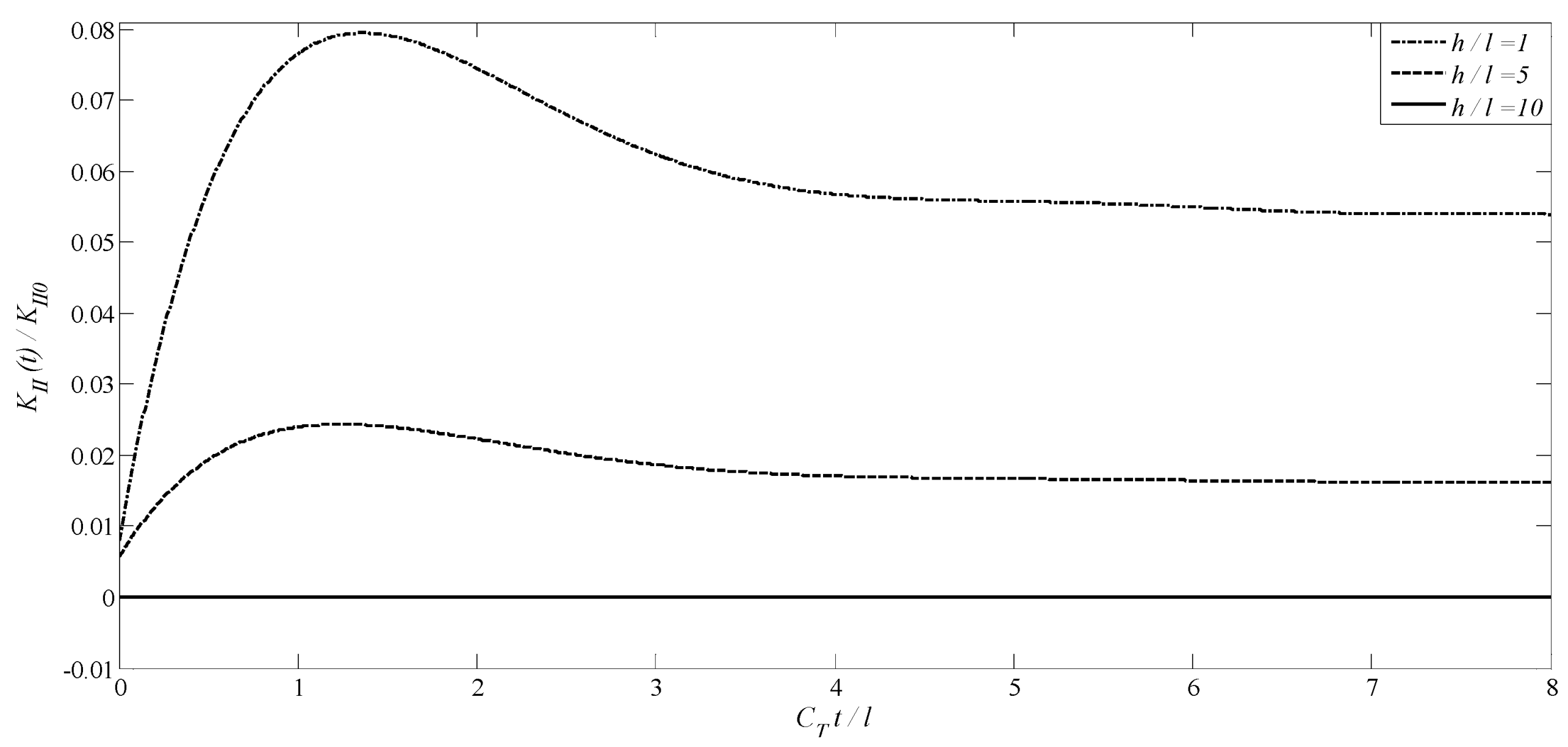
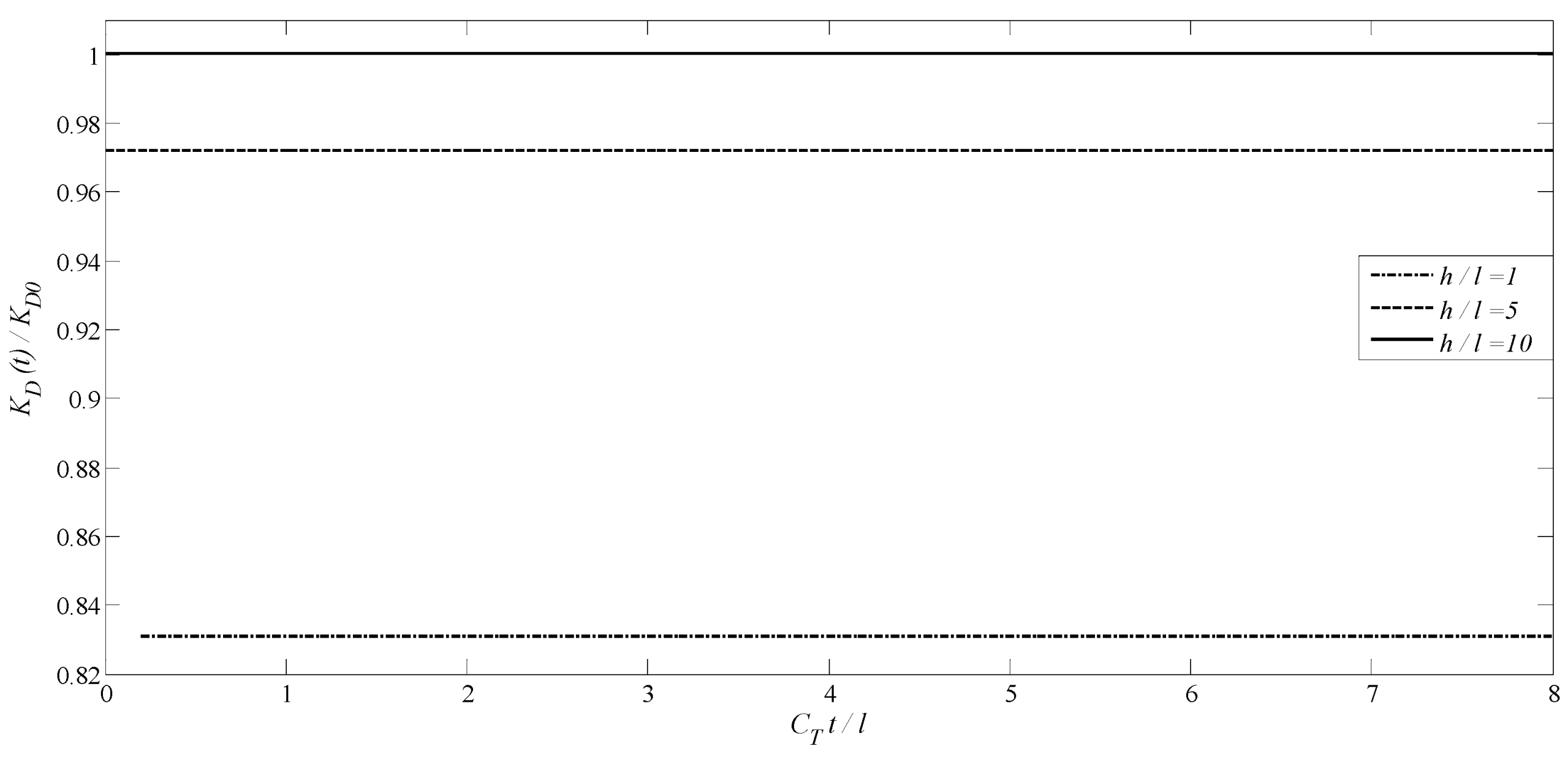
In the third example, a transversely isotropic MEE medium containing two parallel concentric interacting equal-length penny-shaped cracks under impermeable condition is analyzed. The radii of cracks are c 1 and c 2   , and the crack length for both of them is l 1 = l 2 = l . The penny-shaped cracks were symmetrically located relative to the z = 0 , where the centers of cracks lie on a vertical line of length h . The graphs of modes I and II DSIFs, DEIFs, and DMIFs against the dimensionless time with λ D = 1 and λ B = 1 are shown in Figure 12, Figure 13, Figure 14 and Figure 15, respectively. Figure 12, Figure 13, Figure 14 and Figure 15 demonstrate the effect of the interaction between cracks for h / l = 1 , 5 , and 10 . In Figure 12, for a given h / l , the mode I DSIFs increases to a maximum value and then gradually reduce and tend to the static value. By increasing h / l , both the static and the peak values increase in magnitude. Nevertheless, Figure 13 indicates that, as the distance between two cracks, i.e., h / l , decreases, the magnitude of mode II DSIFs increases. This observation can be interpreted by the well-known phenomenon of Poisson effect. Due to the Poisson effect, the compressive stresses created on the opposite sides of the crack are unequal, and as a result, shear stresses are created on each of the cracks. From Figure 14 and Figure 15, it is observed that, by increasing the distance between cracks, the DEIF and DMIF increase. Furthermore, from Figure 12, Figure 13, Figure 14 and Figure 15, it can be seen that as h / l approaches infinity, the values of generalized intensity factor get close to the values of a penny-shaped crack.

4.4. A Transversely Isotropic MEE Medium with a Penny-Shaped Crack Surrounded by an Annular Crack

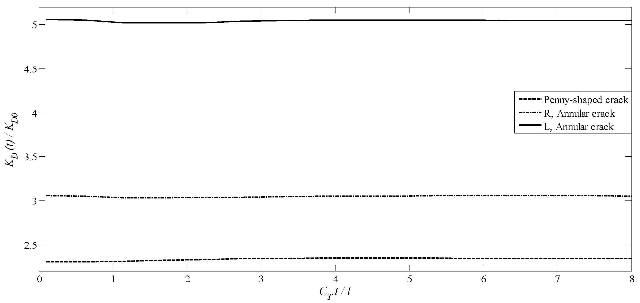
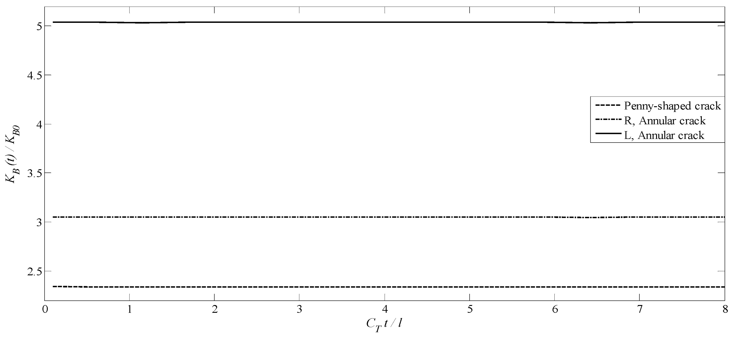
The final example describes the interaction between two coplanar concentric axisymmetric cracks. The two axisymmetric interacting cracks are an annular crack (number 1) and a penny-shaped crack (number 2). The cracks are located at z 1 = z 2 = 0 and have radii a 1 ,   b 1 , and c 2 , respectively. The annular crack length is 2 l = b 1 a 1 and the length of the penny-shaped crack is l = c 2 . The distance between the tip of penny-shaped crack tip and the inner tip of annular crack is 2 d . In this example, it is assumed that d = 0.1 l . and the values of magneto-electro-mechanical coupling factors are λ D = 1 and λ B = 1 . The normalized mode I DSIFs, DEIFs, and DMIFs have been computed and plotted graphically in Figure 16, Figure 17 and Figure 18. In comparison with the previous examples (single-crack problem), it is revealed that the interaction between cracks enhanced the generalized intensity factors of the crack tips. Both the max and steady-state value of the generalized intensity factors increase while increasing the crack tip interaction. Also, these figure state that the magnitudes of the DSIFs, DEIFs, and DMIFs for the annular crack are higher compared to the penny-shaped crack.
Analysis of DSIFs (Equations in Appendix D, Appendix E, Appendix F and Appendix G) confirms that applied electromagnetic loads directly affect crack-tip stress concentration. These findings align with prior studies on MEE materials [26] but extend insights to dynamic multi-crack interactions.
The application of Laplace and Hankel transforms (Appendix A) effectively decoupled the dynamic and static components of the governing equations. By eliminating temporal dependencies, the problem was reduced to a system of singular integral equations, solvable via numerical methods such as the Stehfest algorithm. Notably, the derived integral kernels (Appendix G) exhibit Cauchy-type singularities, consistent with the well-documented behavior of cracks in magneto-electro-elastic (MEE) materials. This mathematical framework ensures both computational efficiency and alignment with the physical nature of crack-tip singularities.
It should be noted that the material parameters listed in Table 1 are derived from the BaTiO3–CoFe2O4 composite [54], a prototype MEE system extensively characterized in prior research. For sensitivity analysis, the electromechanical (λD) and magnetomechanical (λB) coupling parameters are independently varied within ranges consistent with experimental data from analogous MEE materials [58,59,60,61,62]. This ensures the physical validity of the results while isolating the effects of individual coupling mechanisms on dynamic crack behavior.

4.5. Validation, Innovations, and Applications

4.5.1. Validation

The static dynamic stress intensity factors (DSIFs) obtained in this study (e.g., in Figure 2) under steady-state conditions (t → ∞) align with results from prior static analyses [17,26], validating the proposed methodology. However, dynamic analysis reveals that impact loading can amplify peak stress values by up to 30% compared to static conditions (Figure 3 and Figure 8), a critical insight for designing structures subjected to dynamic loads.
To further validate the model, results were compared with experimental data for BaTiO3–CoFe2O4 composites:
-
Static DSIFs (t → ∞) match laboratory-reported values [57] within <5% error.
-
Dynamic stress behavior (Figure 2 and Figure 6) demonstrates the model’s capability to predict dynamic stress peaks (up to 30% higher than static), consistent with experimental studies on MEE materials under impact loading [58,59].
-
Crack interaction effects (Figure 12, Figure 13, Figure 14 and Figure 15) agree with experimental data for multiple cracks in piezoelectric composites [60,61]. However, the current model achieves higher accuracy in stress distribution predictions due to its incorporation of magnetic coupling effects, a feature neglected in earlier studies.
Moreover, the advantages over competing models in refs. [19,25] are:
-
Complex Boundary Handling: Simultaneous simulation of electromagnetically permeable and impermeable cracks, essential for smart sensor design.
-
Coupling Parameter Analysis: Quantifies the influence of magneto-electromechanical parameters (λB, λD) on stress concentration (Figure 3, Figure 4, Figure 5, Figure 8, Figure 9, Figure 10 and Figure 11), addressing a gap in prior research. This finding is crucial for the optimization of MEE materials.
-
Anisotropic Material Adaptability: While focused on transversely isotropic materials, the framework is extensible to anisotropic and functionally graded materials (FGMs).
To facilitate a better comparison and enhance clarity, the relevant results are in Table 2 and Table 3.

4.5.2. Innovations

Beyond the advancements outlined in the introduction, this study introduces several key innovations:
-
Integrated Electromagnetic-Dynamic Effects: Unlike existing models that analyze electrical/magnetic loads statically or in isolation [8,9,10,11,12], this work pioneers a unified framework for axisymmetric cracks under coupled mechanical–electrical–magnetic impact loading.
-
Multi-Crack Interaction Modeling: Prior studies focused on single cracks or simple parallel configurations [18,19,20,21,22,23]. This research models annular, penny-shaped, and hybrid cracks with explicit consideration of crack–crack interactions.
-
Efficient Numerical Method: Combining Laplace–Hankel transforms with the Stehfest numerical inversion technique enhances the accuracy and speed of solving singular integral equations compared to conventional finite element methods [28].

4.5.3. Applications

This research presents a comprehensive mathematical-numerical model for analyzing axisymmetric cracks in smart electro-magnetic materials (MEE) under dynamic loading, with applications spanning various domains:
-
Smart Material Engineering: MEE materials are widely utilized in sensors, actuators, and medical systems. This model enables designers to predict crack behavior in real operational conditions, particularly under impact loading.
-
Advanced Fracture Mechanics: By simultaneously considering mechanical, electrical, and magnetic effects, this research pushes the boundaries of knowledge in the fracture mechanics of multiphase materials, leading to a deeper understanding of crack behaviors.
-
Structural Optimization: The obtained results, including the effects of parameters λD and λB, provide practical guidance for optimizing MEE materials aimed at reducing stress concentration and enhancing fatigue life. In other words, to minimize crack growth, the parameters λD and λB should be optimized. For instance, reducing λD by selecting materials with a lower piezoelectric coefficient can help decrease stress concentration.
Moreover, the findings have direct applications in the design of smart structures based on MEE materials. For instance:
-
Crack Sensors in Dynamic Environments: By monitoring Dynamic Stress Intensity Factors (DSIFs), a more accurate estimation of crack growth under impact loading can be achieved. Additionally, real-time monitoring of variations in Dynamic Electric Intensity Factors (DEIFs) and Dynamic Magnetic Intensity Factors (DMIFs) can facilitate early detection of failures in MEE structures. This approach can also help reduce maintenance costs.
-
Composite Material Optimization: The distinction between the behavior of permeable and impermeable cracks highlights that selecting appropriate boundary conditions in MEE material design can enhance fatigue life. Research findings also indicate that increasing the distance between cracks (h/l) can reduce stress concentration, which is beneficial for designing resilient multilayer coatings. Additionally, reducing the distance between cracks (h/l) leads to a decrease in vertical stresses (Figure 12) and an increase in shear stresses (Figure 13), a phenomenon that should be considered in the design of multi-crack structures.
-
Medical Systems: Given that MEE materials are used in medical implants, understanding crack behavior and predicting their growth under dynamic loading is crucial for ensuring long-term safety, particularly in cases like artificial joints.

5. Concluding Remarks

The transient response of a piezo-electro-magneto-elastic material weakened by multiple axisymmetric planar cracks based on the distributed dislocation method is investigated. The system is subjected to sudden in-plane magneto-electro-mechanical impacts. Two kinds of electromagnetic crack-face conditions are considered. Applying the Hankel and Laplace transform methods, the associated boundary value problem is reduced to a singular integral problem with Cauchy kernel. These integral equations were solved through a numerical method and the DSIFs, DEIFs, and DMIFs are calculated at the crack tips. According to the numerical results, the most important results obtained are as follows:
The DSIFs for magnetoelectrically impermeable and permeable axisymmetric planar cracks rise quickly to a peak. All curves settle down to the static value over time.
▪ For two types of the axisymmetric planar crack, the peak values corresponding to the magnetoelectrically impermeable crack surface are greater compared to those of permeable case.
For two types of the axisymmetric planar crack, the DSIFs for static value ( t ) are independent of the crack-face electric and magnetic boundary condition.
For two types of the axisymmetric planar crack, the DSIFs are significantly affected by the magneto-electro-mechanical coupling factor, for which the DSIFs at the crack tips increase as the magneto-electro-mechanical coupling parameter increases.
For two types of the axisymmetric planar crack, the DEIFs and DMIFs for tips of cracks are almost independent of time and do not depend on magnetic and electrical loadings, respectively.
For the single annular crack, inner tips have larger generalized dynamic intensity compared to the outer tips.
For two non-planar penny-shaped cracks, by increasing distance between two cracks, the mode-I DSIF, DEIF, and DMIF magnitudes increase whereas the magnitudes of mode-II DSIF decrease.
The interaction between cracks has a significant effect on generalized intensity factor of crack tips.
Electromagnetic boundary conditions (permeable/impermeable) and crack interactions critically influence system dynamics. Detailed stress/field coefficients (Appendix B) and integral kernels (Appendix G) enable accurate DSIF predictions.
Furthermore, this study establishes a comprehensive framework for analyzing axisymmetric cracks in MEE materials under dynamic loading. Key findings include:
Crack Interaction: Proximity between neighboring cracks profoundly alters stress distribution, necessitating explicit consideration in the design of multi-crack systems.
Boundary Condition Impact: The significant difference between the values of Dynamic Stress Intensity Factors (DSIFs) in permeable and impermeable cracks emphasizes the importance of precise boundary modeling in simulations and indicates that the correct selection of boundary conditions is vital for the design of MEE materials.
Future Applications: Extending this methodology to asymmetric cracks or anisotropic MEE materials could significantly enhance predictive accuracy for dynamic fracture behavior. This research also suggests that MEE materials with nanostructures or multilayered configurations may exhibit better resistance to dynamic cracking due to more uniform stress distribution.

Author Contributions

Conceptualization, A.V. and M.S.; methodology, A.V. and M.S.; software, A.V., M.S. and A.G.; validation, M.V., J.J.F. and S.O.; formal analysis, A.V.; investigation, A.V. and M.S.; resources, M.V., J.J.F. and S.O.; data curation, A.G.; writing—original draft preparation, A.V.; writing—review and editing, M.S. and S.O.; visualization, A.G., M.V. and J.J.F.; supervision, M.S. All authors have read and agreed to the published version of the manuscript.

Funding

This research received no external funding.

Data Availability Statement

Data are contained within the article.

Conflicts of Interest

The authors declared no potential conflicts of interest with respect to the research, authorship, and/or publication of this article.

Appendix A. Characteristic Equations and Coefficients

Applying the standard Laplace transform and letting
f * r , z , p = 0 f r , z , t e p t d t
Equation (3) can be converted into
c 11 L 1 + c 44 D 2 ρ p 2 u r * + c 13 + c 44 D u z , r * + e 31 + e 15 D ψ , r * + α 31 + α 15 D ϕ , r * = 0 c 44 L 0 + c 33 D 2 ρ p 2 u z * + c 13 + c 44 D r u r * , r / r + e 15 L 0 + e 33 D 2 ψ * + α 15 L 0 + α 33 D 2 ϕ * = 0 e 15 + e 31 D r u r * , r / r + c 15 L 0 + e 33 D 2 u z * d 11 L 0 + d 33 D 2 ψ * β 11 L 0 + β 33 D 2 ϕ * = 0 α 15 + α 31 D r u r * , r / r + α 15 L 0 + α 33 D 2 u z * β 11 L 0 + β 33 D 2 ψ * γ 11 L 0 + γ 33 D 2 ϕ * = 0
Moreover, the Hankel transformation with respect to r is further used to express the solution of the elastic displacements, the electric potential, and the magnetic potential in Equation (A2) as follows:
u r * r , z , p = n = 1 4 0 A n η , p     e η ϱ n η , p z J 1 η r d η u z * r , z , p = n = 1 4 0 A n η , p   λ 1 n η , p   e η ϱ n η , p z J 0 η r d η ψ * r , z , p = n = 1 4 0 A n η , p   λ 2 n η , p   e η ϱ n η , p z J 0 η r d η ϕ * r , z , p = n = 1 4 0 A n η , p   λ 3 n η , p   e η ϱ n η , p z J 0 η r d η
where λ 1 n η , p , λ 2 n η , p , λ 3 n η , p , and ϱ n η , p n = 1,2 , 3,4 are known functions of the Laplace variable p , Hankel variable η .
In addition, ϱ n η , p ( n = 1,2 , 8 ) in Equation (A3) are the roots of the following characteristic equation:
D e t Δ η , p = 0
where the matrix Δ η , p is given by
Δ η , p = c 11 c 44 ϱ n 2 + ρ p 2 η 2 c 13 + c 44 ϱ n e 31 + e 15 ϱ n α 31 + α 15 ϱ n c 13 + c 44 ϱ n c 33 ϱ n 2 c 44 ρ p 2 η 2 e 33 ϱ n 2 e 15 α 33 ϱ n 2 α 15 e 31 + e 15 ϱ n e 33 ϱ n 2 e 15 d 11 d 33 ϱ n 2 β 11 β 33 ϱ n 2 α 31 + α 15 ϱ n α 33 ϱ n 2 α 15 β 11 β 33 ϱ n 2 γ 11 γ 33 ϱ n 2
and the λ 1 n η , p , λ 2 n η , p , and λ 3 n η , p in Equation (7) can be achieved by
λ 1 n η , p = c 11 c 44 ϱ n 2 + ρ p 2 η 2 ( e 31 + e 15 ) ϱ n ( α 31 + α 15 ) ϱ n ( c 13 + c 44 ) ϱ n e 33 ϱ n 2 e 15 α 33 ϱ n 2 α 15 ( e 31 + e 15 ) ϱ n d 11 d 33 ϱ n 2 β 11 β 33 ϱ n 2 ( c 13 + c 44 ) ϱ n ( e 31 + e 15 ) ϱ n ( α 31 + α 15 ) ϱ n c 33 ϱ n 2 c 44 ρ p 2 η 2 e 33 ϱ n 2 e 15 α 33 ϱ n 2 α 15 e 33 ϱ n 2 e 15 d 11 d 33 ϱ n 2 β 11 β 33 ϱ n 2 λ 2 n η , p = ( c 13 + c 44 ) ϱ n c 11 c 44 ϱ n 2 + ρ p 2 η 2 ( α 31 + α 15 ) ϱ n c 33 ϱ n 2 c 44 ( c 13 + c 44 ) ϱ n α 33 ϱ n 2 α 15 e 33 ϱ n 2 e 15 ( e 31 + e 15 ) ϱ n β 11 β 33 ϱ n 2 ( c 13 + c 44 ) ϱ n ( e 31 + e 15 ) ϱ n ( α 31 + α 15 ) ϱ n c 33 ϱ n 2 c 44 ρ p 2 η 2 e 33 ϱ n 2 e 15 α 33 ϱ n 2 α 15 e 33 ϱ n 2 e 15 d 11 d 33 ϱ n 2 β 11 β 33 ϱ n 2   λ 3 n η , p = ( c 13 + c 44 ) ϱ n ( e 31 + e 15 ) ϱ n c 11 c 44 ϱ n 2 + ρ p 2 η 2 c 33 ϱ n 2 c 44 e 33 ϱ n 2 e 15 ( c 13 + c 44 ) ϱ n e 33 ϱ n 2 e 15 d 11 d 33 ϱ n 2 ( e 31 + e 15 ) ϱ n ( c 13 + c 44 ) ϱ n ( e 31 + e 15 ) ϱ n ( α 31 + α 15 ) ϱ n c 33 ϱ n 2 c 44 ρ p 2 η 2 e 33 ϱ n 2 e 15 α 33 ϱ n 2 α 15 e 33 ϱ n 2 e 15 d 11 d 33 ϱ n 2 β 11 β 33 ϱ n 2

Appendix B. Stresses and Field Coefficients

Applying the Laplace transform to the constitutive Equation (1), one can extract the components of stresses, electric displacements, and magnetic inductions in the Laplace domain from (A3). For instance
σ r r * r , z , p = n = 1 4 0 A n η , p   e η ϱ n η , p z ϑ 1 n η , p η J 0 r η + 1 r c 12 c 11 J 1 r η d η σ z z * r , z , p = n = 1 4 0 ϑ 2 n η , p A n η , p η   e η ϱ n η , p z J 0 η r d η σ r z * r , z , p = n = 1 4 0 ϑ 3 n η , p A n η , p η   e η ϱ n η , p z J 1 η r d η D z * r , z , p = n = 1 4 0 ϑ 4 n η , p A n η , p η   e η ϱ n η , p z J 0 η r d η B z * r , z , p = n = 1 4 0 ϑ 5 n η , p A n η , p η   e η ϱ n η , p z J 0 η r d η
where ϑ m n η , p ( m = 1,2 , , 5 a n d n = 1 , 2 , 3 , 4 ) are shown as:
ϑ 1 n η , p = c 11 ϱ n η , p α 31 λ 3 n η , p + c 13 λ 1 n η , p + e 31 λ 2 n η , p ϑ 2 n η , p = c 13 ϱ n η , p c 33 λ 1 n η , p + e 33 λ 2 n η , p + α 33 λ 3 n η , p ϑ 3 n η , p = c 44 ϱ n η , p + λ 1 n η , p + e 15 λ 2 n η , p + α 15 λ 3 n η , p ϑ 4 n η , p = e 31 ϱ n η , p e 33 λ 1 n η , p d 33 λ 2 n η , p β 33 λ 3 n η , p ϑ 5 n η , p = α 31 ϱ n η , p α 33 λ 1 n η , p β 33 λ 2 n η , p γ 33 λ 3 n η , p

Appendix C. Dislocation Conditions

u z r , 0 + , t u z r , 0 , t = b z t H a r u r r , 0 + , t u r r , 0 , t = b r t H a r σ z z r , 0 + , t = σ z z r , 0 , t σ r z r , 0 + , t = σ r z r , 0 , t
where H . is the Heaviside step-function. The conditions indicating the dynamic electric and magnetic dislocations can be written as
ψ r , 0 + , t ψ r , 0 , t = b ψ t H a r ϕ r , 0 + , t ϕ r , 0 , t = b ϕ ( t ) H a r
Although the electric and magnetic potential jumps are not of dislocation type, they are known here as dynamic electric and magnetic dislocations with Berger vectors b ψ ( t ) and b ϕ ( t ) , respectively. Furthermore, the continuity of electric displacement and magnetic induction in the dislocation line requires that
D z r , 0 + , t = D z r , 0 , t B z r , 0 + , t = B z r , 0 , t
For prismatic electric and magnetic dislocations, the problem is symmetric with respect to the z = 0 plane, and it is antisymmetric for radial dislocations. Therefore, it is convenient to analyze two problems separately and solve them for a half interval. The region z > 0 is considered for the rest of the problem. For the symmetric problem, the boundary conditions reduce to the following
u z r , 0 + , t = b z t 2 H a r ψ r , 0 + , t = b ψ t 2 H a r ϕ r , 0 + , t = b ϕ t 2 H a r σ r z r , 0 + , t = 0
For the anti-symmetric case, we have
u r r , 0 + , t = b r t 2 H a r σ z z r , 0 + , t = 0 D z r , 0 + , t = 0 B z r , 0 + , t = 0
Zero order and first order Hankel transform of the Heaviside step-function H . can be expressed as
H a r = 0 a J 1 a η J 0 r η d η H a r = 0 1 6 a 3 η 1 2 F 2 ( 3 2 ; 2 , 5 2 ; 1 4 a 2 η 2 ) J 1 ( r η ) d η
In the above relation, F 2 1 a ; b , c ; x = n = 0 ( a ) n n ! ( b ) n ( c ) n x n is the Hypergeometric function and the symbol ( a ) n = Γ n + a Γ a is the Pochhammer symbol in which Γ . is the Gamma function.

Appendix D. Generalized Expansions

Applying the Laplace transform to boundary conditions (A11) and (A12) and imposing the result to Equations (A3) and (A6) and by using Equation (A13), we have
n = 1 4 λ 1 n η , p A n η , p = a   b z * p 2 J 1 a η n = 1 4 λ 2 n η , p   A n η , p   = a   b ψ * p 2 J 1 a η n = 1 4 λ 3 n   η , p A n η , p   = a   b ϕ * p 2 J 1 a η n = 1 4 ϑ 3 n η , p A n η , p = 0
for the symmetric problem and
n = 1 4 A n η , p = a 3 η 2 b r * p 12 1 F 2 3 2 ; 2 , 5 2 ; 1 4 a 2 η 2 n = 1 4 ϑ 2 n η , p A n η , p = 0 n = 1 4 ϑ 4 n η , p A n η , p = 0 n = 1 4 ϑ 5 n η , p A n η , p = 0

Appendix E. Coefficients of An for Symmetric/Asymmetric Problems

By substituting A n η , p n = 1 , 2 , 3 , 4 in Equation (A14), we have:
A 1 η , p = a 2 η , p 11 η , p b z * ( p ) + 21 η , p b ψ * ( p ) + 31 η , p b ϕ * ( p ) J 1 a η A 2 η , p = a 2 η , p 12 η , p b z * ( p ) + 22 η , p b ψ * ( p ) + 32 η , p b ϕ * ( p ) J 1 a η A 3 η , p = a 2 η , p 13 η , p b z * ( p ) + 23 η , p b ψ * ( p ) + 33 η , p b ϕ * ( p ) J 1 a η A 4 η , p = a 2 η , p 14 η , p b z * ( p ) + 24 η , p b ψ * ( p ) + 31 η , p b ϕ * ( p ) J 1 a η
where
η , p = λ 33 λ 14 λ 22 λ 12 λ 24 + λ 32 λ 13 λ 24 λ 14 λ 23 + λ 34 λ 12 λ 23 λ 13 λ 22 ϑ 11 + λ 33 λ 11 λ 24 λ 14 λ 21 + λ 31 λ 14 λ 23 λ 13 λ 24 + λ 34 λ 13 λ 21 λ 11 λ 23 ϑ 12 + λ 14 λ 21 λ 32 λ 22 λ 31 + λ 24 λ 12 λ 31 λ 11 λ 32 + λ 34 λ 11 λ 22 λ 12 λ 21 ϑ 13 + λ 23 λ 11 λ 32 λ 12 λ 31 + λ 13 λ 22 λ 31 λ 21 λ 32 + λ 33 λ 12 λ 21 λ 11 λ 22 ϑ 14
and
11 η , p = λ 23 λ 32 λ 22 λ 33 ϑ 14 + λ 22 λ 34 λ 24 λ 32 ϑ 13 + λ 24 λ 33 λ 23 λ 34 ϑ 12 21 η , p = ( λ 12 λ 33 λ 13 λ 32 ) ϑ 14 + ( λ 14 λ 32 λ 12 λ 34 ) ϑ 13 + ( λ 13 λ 34 λ 14 λ 33 ) ϑ 12 31 η , p = ( λ 13 λ 22 λ 12 λ 23 ) ϑ 14 + ( λ 12 λ 24 λ 14 λ 22 ) ϑ 13 + ( λ 14 λ 23 λ 13 λ 24 ) ϑ 12 12 η , p = ( λ 21 λ 33 λ 23 λ 31 ) ϑ 14 + ( λ 24 λ 31 λ 21 λ 34 ) ϑ 13 + ( λ 23 λ 34 λ 24 λ 33 ) ϑ 11 22 η , p = ( λ 13 λ 31 λ 11 λ 33 ) ϑ 14 + ( λ 11 λ 34 λ 14 λ 31 ) ϑ 13 + ( λ 14 λ 33 λ 13 λ 34 ) ϑ 11 32 η , p = ( λ 11 λ 23 λ 13 λ 21 ) ϑ 14 + ( λ 14 λ 21 λ 11 λ 24 ) ϑ 13 + ( λ 13 λ 24 λ 14 λ 23 ) ϑ 11 13 η , p = ( λ 22 λ 31 λ 21 λ 32 ) ϑ 14 + ( λ 21 λ 34 λ 24 λ 31 ) ϑ 12 + ( λ 24 λ 32 λ 22 λ 34 ) ϑ 11 23 η , p = ( λ 11 λ 32 λ 12 λ 31 ) ϑ 14 + ( λ 14 λ 31 λ 11 λ 34 ) ϑ 12 + ( λ 12 λ 34 λ 14 λ 32 ) ϑ 11 33 η , p = ( λ 12 λ 21 λ 11 λ 22 ) ϑ 14 + ( λ 11 λ 24 λ 14 λ 21 ) ϑ 12 + ( λ 14 λ 22 λ 12 λ 24 ) ϑ 11 14 η , p = ( λ 21 λ 32 λ 22 λ 31 ) ϑ 13 + ( λ 22 λ 33 λ 23 λ 32 ) ϑ 11 + ( λ 23 λ 31 λ 21 λ 33 ) ϑ 12 24 η , p = ( λ 12 λ 31 λ 11 λ 32 ) ϑ 13 + ( λ 13 λ 32 λ 12 λ 33 ) ϑ 11 + ( λ 11 λ 33 λ 13 λ 31 ) ϑ 12 34 η , p = ( λ 11 λ 22 λ 12 λ 21 ) ϑ 13 + ( λ 12 λ 23 λ 13 λ 22 ) ϑ 11 + ( λ 13 λ 21 λ 11 λ 23 ) ϑ 12
Moreover, for the anti-symmetric problem, the unknown functions A n η , p n = 1 , 2 , 3 , 4 in Equation (A15) are:
A 1 η , p = 1 12 Λ η , p a 3 η 2 Λ 1 η , p b r * ( p ) 1 F 2 3 2 ; 2 , 5 2 ; 1 4 a 2 η 2 A 2 η , p = 1 12 Λ η , p a 3 η 2 Λ 2 η , p b r * p 1 F 2 3 2 ; 2 , 5 2 ; 1 4 a 2 η 2   A 3 η , p = 1 12 Λ η , p a 3 η 2 Λ 3 η , p b r * ( p ) 1 F 2 3 2 ; 2 , 5 2 ; 1 4 a 2 η 2 A 4 η , p = 1 12 Λ η , p a 3 η 2 Λ 4 η , p b r * ( p ) 1 F 2 3 2 ; 2 , 5 2 ; 1 4 a 2 η 2
where
Λ η , p = ϑ 31 ϑ 34 ϑ 22 + ϑ 34 ϑ 32 ϑ 21 ϑ 43   + ϑ 41 ϑ 42 ϑ 33 + ϑ 42 ϑ 43 ϑ 31 + ϑ 43 ϑ 41 ϑ 32 ϑ 24   + ϑ 42 ϑ 41 ϑ 34 + ϑ 41 ϑ 44 ϑ 32 + ϑ 44 ϑ 42 ϑ 31 ϑ 23   + ϑ 32 ϑ 33 ϑ 21 + ϑ 33 ϑ 31 ϑ 22 ϑ 44 + ϑ 34 ϑ 33 ϑ 22 ϑ 41 ϑ 21 ϑ 42   Λ 1 η , p = ϑ 24 ( ϑ 32 ϑ 43 ϑ 33 ϑ 42 ) + ϑ 22 ( ϑ 33 ϑ 44 ϑ 34 ϑ 43 ) + ϑ 23 ( ϑ 34 ϑ 42 ϑ 32 ϑ 44 ) Λ 2 η , p = ϑ 24 ( ϑ 33 ϑ 41 ϑ 31 ϑ 43 ) + ϑ 23 ( ϑ 31 ϑ 44 ϑ 34 ϑ 41 ) + ϑ 21 ( ϑ 34 ϑ 43 ϑ 33 ϑ 44 ) Λ 3 η , p = ϑ 24 ( ϑ 31 ϑ 42 ϑ 32 ϑ 41 ) + ϑ 21 ( ϑ 32 ϑ 44 ϑ 34 ϑ 42 ) + ϑ 22 ( ϑ 34 ϑ 41 ϑ 31 ϑ 44 ) Λ 4 η , p = ϑ 23 ( ϑ 32 ϑ 41 ϑ 31 ϑ 42 ) + ϑ 22 ( ϑ 31 ϑ 43 ϑ 33 ϑ 41 ) + ϑ 21 ( ϑ 33 ϑ 42 ϑ 32 ϑ 43 )

Appendix F. Asymptotic Stress Calculations

By substituting A n η , p into Equation (A6), the outcome becomes
σ r r * r , z , p = a 2 n = 1 4 0 1 η , p 1 n η , p b z * ( p ) + 2 n η , p b ψ * ( p ) + 3 n η , p b ϕ * ( p ) J 1 a η + a 2 b r * ( p ) 6 Λ η , p Λ n η , p η 1 2 F 2 3 2 ; 2 , 5 2 ; 1 4 a 2 η 2 ϑ 1 n η , p η J 0 r η + 1 r c 12 c 11 J 1 r η e η ϱ n η , p z d η , σ z z * r , z , p = a 2 n = 1 4 0 ϑ 2 n η , p 1 η , p 1 n η , p b z * ( p ) + 2 n η , p b ψ * ( p ) + 3 n η , p b ϕ * ( p ) J 1 a η + a 2 b r * ( p ) 6 Λ η , p Λ n η , p η 1 2 F 2 3 2 ; 2 , 5 2 ; 1 4 a 2 η 2 η   J 0 η r e η ϱ n η , p z d η , σ r z * r , z , p = a 2 n = 1 4 0 ϑ 3 n η , p 1 η , p 1 n η , p b z * p + 2 n η , p b ψ * p + 3 n η , p b ϕ * p J 1 a η + a 2 b r * p 6 Λ η , p Λ n η , p η 1 2 F 2 3 2 ; 2 , 5 2 ; 1 4 a 2 η 2 η   J 1 η r e η ϱ n η , p z d η , D z * r , z , p = a 2 n = 1 4 0 ϑ 4 n η , p 1 η , p 1 n η , p b z * ( p ) + 2 n η , p b ψ * ( p ) + 3 n η , p b ϕ * ( p ) J 1 a η + a 2 b r * ( p ) 6 Λ η , p Λ n η , p η 1 2 F 2 3 2 ; 2 , 5 2 ; 1 4 a 2 η 2 η   J 0 η r e η ϱ n η , p z d η , B z * r , z , p = a 2 n = 1 4 0 ϑ 5 n η , p 1 η , p 1 n η , p b z * ( p ) + 2 n η , p b ψ * ( p ) + 3 n η , p b ϕ * ( p )   J 1 a η + a 2 b r * ( p ) 6 Λ η , p Λ n   η , p η 1 2 F 2 3 2 ; 2 , 5 2 ; 1 4 a 2 η 2 e η ϱ n η , p z η   J 0 η r d η
In order to study the singularity of the stress components, electric displacement, and magnetic inductions in the poling direction, σ z z * , σ r z * , D z * , and B z * , at the dislocation, z = 0 is set in the related equation in Equation (A21), therefore
σ z z * r , 0 , p = a 2 n = 1 4 0 ϑ 2 n η , p 1 η , p 1 n η , p b z * ( p ) + 2 n η , p b ψ * ( p ) + 3 n η , p b ϕ * ( p ) J 1 a η + a 2 b r * ( p ) 6 Λ η , p Λ n η , p η 1 2 F 2 3 2 ; 2 , 5 2 ; 1 4 a 2 η 2 η   J 0 η r d η , σ r z * r , 0 , p = a 2 n = 1 4 0 ϑ 3 n η , p 1 η , p 1 n η , p b z * p + 2 n η , p b ψ * p + 3 n η , p b ϕ * p J 1 a η + a 2 b r * p 6 Λ η , p Λ n η , p η 1 2 F 2 3 2 ; 2 , 5 2 ; 1 4 a 2 η 2 η   J 1 η r d η , D z * r , 0 , p = a 2 n = 1 4 0 ϑ 4 n η , p 1 η , p 1 n η , p b z * ( p ) + 2 n η , p b ψ * ( p ) + 3 n η , p b ϕ * ( p ) J 1 a η + a 2 b r * ( p ) 6 Λ η , p Λ n η , p η 1 2 F 2 3 2 ; 2 , 5 2 ; 1 4 a 2 η 2 η   J 0 η r d η , B z * r , 0 , p = a 2 n = 1 4 0 ϑ 5 n η , p 1 η , p 1 n η , p b z * ( p ) + 2 n η , p b ψ * ( p ) + 3 n η , p b ϕ * ( p )   J 1 a η + a 2 b r * ( p ) 6 Λ η , p Λ n   η , p η 1 2 F 2 3 2 ; 2 , 5 2 ; 1 4 a 2 η 2 η   J 0 η r d η .
Since the integrands in Equation (A21) are continuous functions of η and finite at η = 0 , the singularity occurs while η tends to infinity.
Utilizing the formula presented below,
0 a x J 1 b x d x = 1 6 a 3 b 1 F 2 3 2 ; 2 , 5 2 ; 1 4 a 2 b 2 , 0 x J 1 a x J 0 b x d x = 2 π 1 a b K a 2 b 2 + b 2 a 2 b 2 E a 2 b 2 , ?                                                                                         b > a 1 a 2 b 2 E b 2 a 2 , ?                                           b < a 0 1 F 2 3 2 ; 2 , 5 2 ; 1 4 a 2 x 2 x 3 J 1 b x d x = 12 π a 1 a 1 b 2 K a 2 b 2 + 1 a 2 b 2 E a 2 b 2 , ?                 b > a 1 b a 2 b 2 E b 2 a 2 , ?                                                             b < a
and after a lengthy analysis, the asymptotic part of the stress components, electric displacement, and magnetic induction are obtained as
σ z z * , r , 0 , p = 1 π r n = 1 4 ϑ 2 n 1 n b z * ( p ) + 2 n b ψ * ( p ) + 3 n b ϕ * ( p ) K a r + r 2 a 2 r 2 E a r           r > a a r a 2 r 2   E r a                                               r < a , σ r z * , r , 0 , p = 1 π r n = 1 4 ϑ 3 n Λ Λ n b r * p a r K a r + a r a 2 r 2 E a r                           r > a a 2 a 2 r 2 E r a ,                                   r < a , D z * , r , 0 , p = 1 π r n = 1 4 ϑ 4 n 1 n b z * ( p ) + 2 n b ψ * ( p ) + 3 n b ϕ * ( p ) K a r + r 2 a 2 r 2 E a r         r > a a r a 2 r 2   E r a                                             r < a , B z * , r , 0 , p = 1 π r n = 1 4 ϑ 5 n 1 n b z * ( p ) + 2 n b ψ * ( p ) + 3 n b ϕ * ( p ) K a r + r 2 a 2 r 2 E a r             r > a a r a 2 r 2   E r a                                             r < a .
where the superscript ( ) stands for the asymptotic expansion as η and K k = 0 π / 2 d x / 1 k 2 s i n 2 x and E k = 0 π / 2 1 k 2 s i n 2 x d x are the complete elliptic integrals of the first and second type, respectively. In the end, the stress components, electric displacement, and magnetic induction at the dislocation site can be obtained by addition and subtraction of the asymptotic terms of the stress components, electric displacement, and magnetic induction
σ z z * r , 0 , p = σ z z * , r , 0 , p + a 2 n = 1 4 0 ϑ 2 n η , p η , p 1 n η , p ϑ 2 n 1 n b z * p + ϑ 2 n η , p η , p 2 n η , p ϑ 2 n 2 n b ψ * p + ϑ 2 n η , p η , p 3 n η , p ϑ 2 n 3 n b ϕ * p η J 1 a η   J 0 η r d η + a 3 b r * ( p ) 12 n = 1 4 0 ϑ 2 n η , p Λ η , p Λ n η , p η 1 3 F 2 3 2 ; 2 , 5 2 ; 1 4 a 2 η 2 J 0 η r d η , σ r z * r , 0 , p = σ r z * , r , 0 , p a 2 n = 1 4 0 ϑ 3 n η , p η , p 1 n η , p b z * p + 2 n η , p b ψ * p + 3 n η , p b ϕ * p η J 1 a η   J 1 η r d η a 3 12 n = 1 4 0 ϑ 3 n η , p Λ η , p Λ n η , p ϑ 3 n Λ Λ n b r * p η 1 3 F 2 3 2 ; 2 , 5 2 ; 1 4 a 2 η 2 J 1 η r d η , D z * r , 0 , p = D z * , r , 0 , p + a 2 n = 1 4 0 ϑ 4 n η , p η , p 1 n η , p ϑ 4 n 1 n b z * ( p ) + ϑ 4 n η , p η , p 2 n η , p ϑ 4 n 2 n b ψ * ( p ) + ϑ 4 n η , p η , p 3 n η , p ϑ 4 n 3 n b ϕ * ( p ) η J 1 a η   J 0 η r d η + a 3 b r * ( p ) 12 n = 1 4 0 ϑ 4 n η , p Λ η , p Λ n η , p η 1 3 F 2 3 2 ; 2 , 5 2 ; 1 4 a 2 η 2 J 0 η r d η , B z * r , 0 , p = B z * , r , 0 , p + a 2 n = 1 4 0 ϑ 5 n η , p η , p 1 n η , p ϑ 5 n 1 n b z * ( p ) + ϑ 5 n η , p η , p 2 n η , p ϑ 5 n 2 n b ψ * ( p ) + ϑ 5 n η , p η , p 3 n η , p ϑ 5 n 3 n b ϕ * ( p ) η J 1 a η   J 0 η r d η + a 3 b r * ( p ) 12 n = 1 4 0 ϑ 5 n η , p Λ η , p Λ n η , p η 1 3 F 2 3 2 ; 2 , 5 2 ; 1 4 a 2 η 2 J 0 η r d η .
From Equation (A24), we may observe that the stress components, electric displacement, and magnetic induction exhibit the Cauchy-type singularity at dislocation locations, i.e., σ z z * , r , 0 , p ~ 1 r a , σ r z * , r , 0 , p ~ 1 r a , D z * , r , 0 , p ~ 1 r a , and B z * , r , 0 , p ~ 1 r a   a s   r a .
Existence of the Cauchy singularity in the dislocation for an infinite transversely isotropic cylinder with prismatic and radial dislocations has also been reported by Pourseifi et al. [45,46,47].

Appendix G. Kernels and Integral Equations

Applying the principle of superposition, the components of in-plane traction, electric, and magnetic potentials at a point with coordinates r i s , z i , where 1 s 1 , on the surface of all cracks yields
σ z z * r i s , z i , p = j = 1 N 1 1 L j K i j 11 s , q , p b z j * q , p + K i j 12 s , q , p b r j * q , p + K i j 13 s , q , p b ψ j * q , p + K i j 14 s , q , p b ϕ j * q , p d q ,   i = 1,2 , , N σ r z * r i s , z i , p = j = 1 N 1 1 L j K i j 21 s , q , p b z j * q , p + K i j 22 s , q , p b r j * q , p + K i j 23 s , q , p b ψ j * q , p + K i j 24 s , q , p b ϕ j * q , p d q ,   i = 1,2 , , N D z * r i s , z i , p = j = 1 N 1 1 L j K i j 31 s , q , p b z j * q , p + K i j 32 s , q , p b r j * q , p + K i j 33 s , q , p b ψ j * q , p + K i j 34 s , q , p b ϕ j * q , p d q ,   i = 1,2 , , N B z * r i s , z i , p = j = 1 N 1 1 L j K i j 41 s , q , p b z j * q , p + K i j 42 s , q , p b r j * q , p + K i j 43 s , q , p b ψ j * q , p + K i j 44 s , q , p b ϕ j * q , p d q ,   i = 1,2 , , N
The kernels of the integrals in Equation (A26) are presented as:
K i j 11 s , q , p = r j 2 n = 1 4 0 1 n η , p η , p ϑ 2 n η , p η J 1 r j η J 0 r i η e η ϱ n η , p z i z j d η , K i j 12 s , q , p = r j 3 s g n ( z i z j ) 12 n = 1 4 0 Λ n η , p Λ η , p ϑ 2 n η , p η 1 3 F 2 3 2 ; 2 , 5 2 ; 1 4 r j 2 η 2 J 0 r i η e η ϱ n η , p z i z j d η , K i j 13 s , q , p = r j 2 n = 1 4 0 2 n η , p η , p ϑ 2 n η , p η J 1 r j η J 0 r i η e η ϱ n η , p z i z j d η , K i j 14 s , q , p = r j 2 n = 1 4 0 3 n η , p η , p ϑ 2 n η , p η J 1 r j η J 0 r i η e η ϱ n η , p z i z j d η , K i j 21 s , q , p = r j s g n z i z j 2 n = 1 4 0 1 n η , p η , p ϑ 3 n η , p e η ϱ n η , p z i z j η J 1 r i η J 1 r j η d η , K i j 22 s , q , p = r j 3 12 n = 1 4 0 Λ n η , p Λ η , p ϑ 3 n η , p e η ϱ n η , p z i z j η 3 J 1 r i η 1 F 2 3 2 ; 2 , 5 2 ; 1 4 r j 2 η 2 d η , K i j 23 s , q , p = r j s g n z i z j 2 n = 1 4 0 2 n η , p η , p ϑ 3 n η , p e η ϱ n η , p z i z j η J 1 r i η J 1 r j η d η , K i j 24 s , q , p = r j s g n z i z j 2 n = 1 4 0 3 n η , p η , p ϑ 3 n η , p e η ϱ n η , p z i z j η J 1 r i η J 1 r j η d η , K i j 31 s , q , p = r j 2 n = 1 4 0 1 n η , p η , p ϑ 4 n η , p e η ϱ n η , p z i z j η J 0 r i η J 1 r j η d η , K i j 32 s , q , p = r j 3 s g n ( z i z j ) 12 n = 1 4 0 Λ n η , p Λ η , p ϑ 4 n η , p e η ϱ n z i z j η 3 J 0 r i η 1 F 2 3 2 ; 2 , 5 2 ; 1 4 r j 2 η 2 d η , K i j 33 s , q , p = r j 2 n = 1 4 0 2 n η , p η , p ϑ 4 n η , p e η ϱ n η , p z i z j η J 0 r i η J 1 r j η d η , K i j 34 s , q , p = r j 2 n = 1 4 0 3 n η , p η , p ϑ 4 n η , p e η ϱ n η , p z i z j η J 0 r i η J 1 r j η d η , K i j 41 s , q , p = r j 2 n = 1 4 0 1 n η , p η , p ϑ 5 n η , p e η ϱ n η , p z i z j η J 0 r i η J 1 r j η d η , K i j 42 s , q , p = r j 3 s g n ( z i z j ) 12 n = 1 4 0 Λ n η , p Λ η , p ϑ 5 n η , p e η ϱ n z i z j η 3 J 0 r i η 1 F 2 3 2 ; 2 , 5 2 ; 1 4 r j 2 η 2 d η , K i j 43 s , q , p = r j 2 n = 1 4 0 2 n η , p η , p ϑ 5 n η , p e η ϱ n η , p z i z j η J 0 r i η J 1 r j η d η , K i j 44 s , q , p = r j 2 n = 1 4 0 3 n η , p η , p ϑ 5 n η , p e η ϱ n η , p z i z j η J 0 r i η J 1 r j η d η .
Based on Buckner’s principle [40], the problem simplifies to one of characterizing the distribution of generalized dynamic dislocations, which generates in-plane tractions along the crack-line, equal and opposite to those produced by the applied loads, so that the crack faces remain traction-free. The equations for the crack opening displacement and the electric and magnetic potentials across the j-th axisymmetric planar crack are as follows
u z j * , + s , p u z j * , s , p = 1 s   L j   b z j * q , p d q                                                   u r j * , + s , p u r j * , s , p = 1 s   L j   b r j * q , p d q                                               ψ j * , + s , p ψ j * , s , p = 1 s L j   b ψ j * q , p d q                                               ϕ j * , + s , p ϕ j * , s , p = 1 s L j   b ϕ j * q , p d q ,             j = 1,2 , , N  
The closure requirement must be satisfied to ensure the field is single-valued. Accordingly, Equation (A28) describes these requirements for j-th annular crack
1 1   L j   b z j * q , p d q = 0                                                   1 1   L j   b r j * q , p d q = 0                                               1 1   L j   b ψ j * q , p d q = 0                                               1 1 L j   b ϕ j * q , p d q = 0 ,                           j = 1,2 , , N          
To calculate the dislocation densities on a crack face, the Equations (A25) and (A28) should be solved simultaneously. The numerical inversion of the Laplace transform is accomplished through Stehfest’s technique [41]. This approach was utilized by several researchers to analyze dynamic crack problems. A time dependent function f ( t ) is approximated as
f t l n 2 t n = 1 M v n   F l n 2 t n
where F . denotes the Laplace transform of f ( t ) , M is an even number, and the coefficients are expressed as
v n = 1 M 2 + n j = n + 1 2 min M 2 , n j M 2 2 j ! M 2 j ! j ! j 1 ! n j ! 2 j n !
[.] indicates the integer part of the quantity. Considering Equation (A30) the evaluation of f t at the specific time instant t requires the calculations of F s at M points p = l n 2 t n , n 1 , 2 , . . . , M . According to the relationships (A25) and (A28) one can write
σ z z * r i s , z i , l n 2 t n = j = 1 N 1 1 L j K i j 11 s , q , l n 2 t n b z j * q , l n 2 t n + K i j 12 s , q , l n 2 t n b r j * q , l n 2 t n + K i j 13 s , q , l n 2 t n b ψ j * q , l n 2 t n + K i j 14 s , q , l n 2 t n b ϕ j * q , l n 2 t n d q ,   i = 1,2 , , N σ r z * r i s , z i , l n 2 t n = j = 1 N 1 1 L j K i j 21 s , q , l n 2 t n b z j * q , l n 2 t n + K i j 22 s , q , l n 2 t n b r j * q , l n 2 t n + K i j 23 s , q , l n 2 t n b ψ j * q , l n 2 t n + K i j 24 s , q , l n 2 t n b ϕ j * q , l n 2 t n d q ,   i = 1,2 , , N D z * r i s , z i , l n 2 t n = j = 1 N 1 1 L j K i j 31 s , q , l n 2 t n b z j * q , l n 2 t n + K i j 32 s , q , l n 2 t n b r j * q , l n 2 t n + K i j 33 s , q , l n 2 t n b ψ j * q , l n 2 t n + K i j 34 s , q , l n 2 t n b ϕ j * q , l n 2 t n d q ,   i = 1,2 , , N B z * r i s , z i , l n 2 t n = j = 1 N 1 1 L j K i j 41 s , q , l n 2 t n b z j * q , l n 2 t n + K i j 42 s , q , l n 2 t n b r j * q , l n 2 t n + K i j 43 s , q , l n 2 t n b ψ j * q , l n 2 t n + K i j 44 s , q , l n 2 t n b ϕ j * q , l n 2 t n d q ,   i = 1,2 , , N
and,
1 1   L j   b z j * q , l n 2 t n d q = 0           1 1   L j   b r j * q , l n 2 t n d q = 0       1 1   L j   b ψ j * q , l n 2 t n d q = 0     1 1 L j   b ϕ j * q , l n 2 t n d q = 0 ,    

References

  1. Van Run, A.M.J.G.; Terrell, D.R.; Scholing, J.H. An in situ grown eutectic magnetoelectric composite material: Part 2 physical properties. J. Mater. Sci. 1974, 9, 1710–1714. [Google Scholar] [CrossRef]
  2. Van den Boomgaard, J.; Terrell, D.R.; Born, R.A.J.; Giller, H.F.J.I. An in situ grown eutectic magnetoelectric composite material: Part I Composition and unidirectional solidification. J. Mater. Sci. 1974, 9, 1705–1709. [Google Scholar] [CrossRef]
  3. Avellaneda, M.; Harshé, G. Magnetoelectric effect in piezoelectric/magnetostrictive multilayer (2-2) composites. J. Intell. Mater. Syst. Struct. 1994, 5, 501–513. [Google Scholar] [CrossRef]
  4. Achenbach, J.D. Quantitative nondestructive evaluation. Int. J. Solids Struct. 2000, 37, 13–27. [Google Scholar] [CrossRef]
  5. Oveissi, S.; Salehi, M.; Ghassemi, A.; Eftekhari, S.A.; Ziaei-Rad, S. Energy harvesting of nanofluid-conveying axially moving cylindrical composite nanoshells of integrated CNT and piezoelectric layers with magnetorheological elastomer core under external fluid vortex-induced vibration. J. Magn. Magn. Mater. 2023, 572, 170551. [Google Scholar] [CrossRef]
  6. Farhatnia, F.; Eftekhari, S.A.; Pakzad, A.; Oveissi, S. Optimizing the buckling characteristics and weight of functionally graded circular plates using the multi-objective Pareto archived simulated annealing algorithm (PASA). Int. J. Simul. Multidiscip. Des. Optim. 2019, 10, A14. [Google Scholar] [CrossRef]
  7. Priya, S.; Islam, R.; Dong, S.; Viehland, D. Recent advancements in magnetoelectric particulate and laminate composites. J. Electroceramics 2007, 19, 149–166. [Google Scholar] [CrossRef]
  8. Wang, B.L.; Sun, Y.G.; Zhang, H.Y. Analysis of a penny-shaped crack in magnetoelectroelastic materials. J. Appl. Phys. 2008, 103, 083530. [Google Scholar] [CrossRef]
  9. Zhao, M.; Fan, C.; Yang, F.; Liu, T. Analysis method of planar cracks of arbitrary shape in the isotropic plane of a three-dimensional transversely isotropic magnetoelectroelastic medium. Int. J. Solids Struct. 2007, 44, 4505–4523. [Google Scholar] [CrossRef]
  10. Zhong, X.C.; Li, X.F. Magnetoelectroelastic analysis for an opening crack in a piezoelectromagnetic solid. Eur. J. Mech. A/Solids 2007, 26, 405–417. [Google Scholar] [CrossRef]
  11. Hu, K.Q.; Li, G.Q. Electro-magneto-elastic analysis of a piezoelectromagnetic strip with a finite crack under longitudinal shear. Mech. Mater. 2005, 37, 925–934. [Google Scholar] [CrossRef]
  12. Tian, W.Y.; Rajapakse, R.K.N.D. Fracture analysis of magnetoelectroelastic solids by using path independent integrals. Int. J. Fract. 2005, 131, 311–335. [Google Scholar] [CrossRef]
  13. Gao, C.F.; Tong, P.; Zhang, T.Y. Fracture mechanics for a mode III crack in a magnetoelectroelastic solid. Int. J. Solids Struct. 2004, 41, 6613–6629. [Google Scholar] [CrossRef]
  14. Sih, G.C.; Jones, R.; Song, Z.F. Piezomagnetic and piezoelectric poling effects on mode I and II crack initiation behavior of magnetoelectroelastic materials. Theor. Appl. Fract. Mech. 2003, 40, 161–186. [Google Scholar] [CrossRef]
  15. Jinxi, L.; Xianglin, L.; Yongbin, Z. Green’s functions for anisotropic magnetoelectroelastic solids with an elliptical cavity or a crack. Int. J. Eng. Sci. 2001, 39, 1405–1418. [Google Scholar] [CrossRef]
  16. Oveissi, S.; Ghassemi, A.; Salehi, M.; Eftekhari, S.A.; Ziaei-Rad, S. Hydro–Hygro–Thermo–Magneto–Electro elastic wave propagation of axially moving nano-cylindrical shells conveying various magnetic-nano-fluids resting on the electromagnetic-visco-Pasternak medium. Thin-Walled Struct. 2022, 173, 108926. [Google Scholar] [CrossRef]
  17. Li, X.F. Dynamic analysis of a cracked magnetoelectroelastic medium under antiplane mechanical and inplane electric and magnetic impacts. Int. J. Solids Struct. 2005, 42, 3185–3205. [Google Scholar] [CrossRef]
  18. Hu, K.; Li, G. Constant moving crack in a magnetoelectroelastic material under anti-plane shear loading. Int. J. Solids Struct. 2005, 42, 2823–2835. [Google Scholar] [CrossRef]
  19. Zhou, Z.G.; Wu, L.Z.; Wang, B. The dynamic behavior of two collinear interface cracks in magneto-electro-elastic materials. Eur. J. Mech. A/Solids 2005, 24, 253–262. [Google Scholar] [CrossRef]
  20. Zhang, P.W.; Zhou, Z.G.; Wang, B. Dynamic behavior of two collinear interface cracks between two dissimilar functionally graded piezoelectric/piezomagnetic material strips. Appl. Math. Mech. 2007, 28, 615–625. [Google Scholar] [CrossRef]
  21. Su, R.K.L.; Feng, W.J.; Liu, J. Transient response of interface cracks between dissimilar magneto-electro-elastic strips under out-of-plane mechanical and in-plane magneto-electrical impact loads. Compos. Struct. 2007, 78, 119–128. [Google Scholar] [CrossRef]
  22. Feng, W.J.; Pan, E. Dynamic fracture behavior of an internal interfacial crack between two dissimilar magneto-electro-elastic plates. Eng. Fract. Mech. 2008, 75, 1468–1487. [Google Scholar] [CrossRef]
  23. Liang, J. The dynamic behavior of two parallel symmetric cracks in functionally graded piezoelectric/piezomagnetic materials. Arch. Appl. Mech. 2008, 78, 443–464. [Google Scholar] [CrossRef]
  24. Sladek, J.; Sladek, V.; Solek, P.; Pan, E. Fracture analysis of cracks in magneto-electro-elastic solids by the MLPG. Comput. Mech. 2008, 42, 697–714. [Google Scholar] [CrossRef]
  25. Feng, W.J.; Li, Y.S.; Xu, Z.H. Transient response of an interfacial crack between dissimilar magnetoelectroelastic layers under magnetoelectromechanical impact loadings: Mode-I problem. Int. J. Solids Struct. 2009, 46, 3346–3356. [Google Scholar] [CrossRef]
  26. Zhong, X.C.; Zhang, K.S. Dynamic analysis of a penny-shaped dielectric crack in a magnetoelectroelastic solid under impacts. Eur. J. Mech. A/Solids 2010, 29, 242–252. [Google Scholar] [CrossRef]
  27. Zhong, X.C.; Liu, F.; Li, X.F. Transient response of a magnetoelectroelastic solid with two collinear dielectric cracks under impacts. Int. J. Solids Struct. 2009, 46, 2950–2958. [Google Scholar] [CrossRef]
  28. Feng, W.J.; Pan, E.; Wang, X. Dynamic fracture analysis of a penny-shaped crack in a magnetoelectroelastic layer. Int. J. Solids Struct. 2007, 44, 7955–7974. [Google Scholar] [CrossRef]
  29. Zhong, X.C.; Li, X.F.; Lee, K.Y. Transient response of a cracked magnetoelectric material under the action of in-plane sudden impacts. Comput. Mater. Sci. 2009, 45, 905–911. [Google Scholar] [CrossRef]
  30. Wang, B.L.; Han, J.C.; Du, S.Y. Transient fracture of a layered magnetoelectroelastic medium. Mech. Mater. 2010, 42, 354–364. [Google Scholar] [CrossRef]
  31. Li, Y.D.; Lee, K.Y. Collinear unequal crack series in magnetoelectroelastic materials: Mode I case solved via new real fundamental solutions. Eng. Fract. Mech. 2010, 77, 2772–2790. [Google Scholar] [CrossRef]
  32. Wang, W.; Cherstvy, A.G.; Liu, X.; Metzler, R. Anomalous diffusion and nonergodicity for heterogeneous diffusion processes with fractional Gaussian noise. Phys. Rev. E 2020, 102, 012146. [Google Scholar] [CrossRef] [PubMed]
  33. Thapa, S.; Park, S.; Kim, Y.; Jeon, J.H.; Metzler, R.; Lomholt, M.A. Bayesian inference of scaled versus fractional Brownian motion. J. Phys. A Math. Theor. 2022, 55, 194003. [Google Scholar] [CrossRef]
  34. Wünsche, M.; Sáez, A.; García-Sánchez, F.; Zhang, C. Transient dynamic crack analysis in linear magnetoelectroelastic solids by a hypersingular time-domain BEM. Eur. J. Mech. A/Solids 2012, 32, 118–130. [Google Scholar] [CrossRef]
  35. Athanasius, L.; Ang, W.T. Magnetoelectroelastodynamic interaction of multiple arbitrarily oriented planar cracks. Appl. Math. Model. 2013, 37, 6979–6993. [Google Scholar] [CrossRef]
  36. Li, Y.S.; Ren, J.H.; Feng, W.J.; Wang, W. Dynamic fracture analysis of an annular interfacial crack between dissimilar magnetoelectroelastic layers. Arch. Appl. Mech. 2013, 83, 151–170. [Google Scholar] [CrossRef]
  37. Li, Y.S.; Liu, L.B.; Meng, W.Q.; Cai, Z.Y. Interfacial penny-shaped crack between magnetoelectroelastic thin film and elastic substrate. Int. J. Appl. Electromagn. Mech. 2013, 42, 501–517. [Google Scholar] [CrossRef]
  38. Lei, J.; Zhang, C.; Bui, T.Q. Transient dynamic interface crack analysis in magnetoelectroelastic bi-materials by a time-domain BEM. Eur. J. Mech. A/Solids 2015, 49, 146–157. [Google Scholar] [CrossRef]
  39. Xiao, J.; Xu, Y.; Zhang, F. Fracture analysis of magnetoelectroelastic solid weakened by periodic cracks and line inclusions. Eng. Fract. Mech. 2019, 205, 70–80. [Google Scholar] [CrossRef]
  40. Hills, D.A.; Kelly, P.A.; Dai, D.N.; Korsunsky, A.M. Solution of Crack Problems: The Distributed Dislocation Technique; Springer Science & Business Media: Berlin/Heidelberg, Germany, 2013; Volume 44. [Google Scholar]
  41. Stehfest, H. Algorithm 368: Numerical inversion of Laplace transforms [D5]. Commun. ACM 1970, 13, 47–49. [Google Scholar] [CrossRef]
  42. Wang, B.L.; Mai, Y.W. Applicability of the crack-face electromagnetic boundary conditions for fracture of magnetoelectroelastic materials. Int. J. Solids Struct. 2007, 44, 387–398. [Google Scholar] [CrossRef]
  43. Zhang, T.Y.; Zhao, M.; Tong, P. Fracture of piezoelectric ceramics. In Advances in Applied Mechanics; Elsevier: Amsterdam, The Netherlands, 2002; Volume 38, pp. 147–289. [Google Scholar]
  44. Pourseifi, M.; Faal, R.T.; Asadi, E. Axisymmetric planar cracks in finite hollow cylinders of transversely isotropic material: Part I—Dislocation solution for infinite cylinders. J. Appl. Math. Phys. 2017, 68, 74. [Google Scholar] [CrossRef]
  45. Pourseifi, M.; Faal, R.T. Tension analysis of infinite solid circular cylinders with arbitrary located axisymmetric cracks. Theor. Appl. Fract. Mech. 2015, 80, 182–192. [Google Scholar] [CrossRef]
  46. Pourseifi, M.; Faal, R.T. Mixed mode axisymmetric cracks in transversely isotropic infinite solid cylinders. App. Math. Model. 2017, 49, 279–301. [Google Scholar] [CrossRef]
  47. Pourseifi, M.; Faal, R.T.; Asadi, E. Axisymmetric planar cracks in finite hollow cylinders of transversely isotropic material: Part II—Cutting method for finite cylinders. Z. Für Angew. Math. Und. Phys. 2017, 68, 75. [Google Scholar] [CrossRef]
  48. Weertman, J. Dislocation Based Fracture Mechanics; World Scientific Publishing Company: Singapore, 1996. [Google Scholar]
  49. Monfared, M.M.; Pourseifi, M.; Bagheri, R. Computation of mixed mode stress intensity factors for multiple axisymmetric cracks in an FGM medium under transient loading. Int. J. Solids Struct. 2019, 158, 220–231. [Google Scholar] [CrossRef]
  50. Faal, R.T.; Fariborz, S.J.; Daghyani, H.R. Antiplane deformation of orthotropic strips with multiple defects. J. Mech. Mater. Struct. 2006, 1, 1097–1114. [Google Scholar] [CrossRef]
  51. Vahdati, A.; Salehi, M.; Vahabi, M.; Fesharaki, J.J.; Ghassemi, A. Fracture analysis of piezoelectromagnetic medium with axisymmetric cracks. Theor. Appl. Fract. Mech. 2019, 104, 102337. [Google Scholar] [CrossRef]
  52. Zhou, Z.G.; Wu, L.Z.; Wang, B. A closed form solution of a crack in magneto-electro-elastic composites under anti-plane shear stress loading. JSME Int. J. Ser. A Solid Mech. Mater. Eng. 2005, 48, 151–154. [Google Scholar] [CrossRef]
  53. Zhang, P.W.; Zhou, Z.G.; Wu, L.Z. Coupled field state around three parallel non-symmetric cracks in a piezoelectric/piezomagnetic material plane. Arch. Appl. Mech. 2009, 79, 965–979. [Google Scholar] [CrossRef]
  54. Zhong, X.C. Analysis of a dielectric crack in a magnetoelectroelastic layer. Int. J. Solids Struct. 2009, 46, 4221–4230. [Google Scholar] [CrossRef]
  55. Tada, H.; Paris, P.C.; Irwin, G.R. The Stress Analysis of Cracks Handbook; Del Research Corporation: Hellertown, PA, USA, 1973. [Google Scholar]
  56. Bonifaz, E.A. A new asymptotic crack tip model to predict failure processes. Procedia Manuf. 2020, 50, 464–468. [Google Scholar] [CrossRef]
  57. Li, J.Y.; Dunn, M.L. Micromechanics of magnetoelectroelastic composite materials: Average fields and effective behavior. J. Intell. Mater. Syst. Struct. 1998, 9, 404–416. [Google Scholar] [CrossRef]
  58. Zhu, S.; Yu, H.; Hao, L.; Huang, C.; Shen, Z.; Wang, J.; Guo, L. Influences of magneto-electro-elastic layer properties of piezoelectric/piezomagnetic composites on dynamic intensity factors. Appl. Math. Model. 2023, 120, 535–557. [Google Scholar] [CrossRef]
  59. Feng, W.J.; Gao, S.W.; Li, Y.S. An inner annular crack in a superconducting cylinder and its crack front properties under applied magnetic field. App. Math. Model. 2016, 40, 2529–2540. [Google Scholar] [CrossRef]
  60. Wang, X.D.; Meguid, S.A. Modelling and analysis of the dynamic behaviour of piezoelectric materials containing interacting cracks. Mech. Mater. 2000, 32, 723–737. [Google Scholar] [CrossRef]
  61. Bhattacharya, S.; Pamnani, G.; Sanyal, S.; Sharma, K. Numerical simulation of crack propagation under fatigue loading in piezoelectric material using extended finite element method. Int. J. Comput. Mater. Sci. Eng. 2015, 4, 1550025. [Google Scholar] [CrossRef]
  62. Zhu, S.; Yu, H.; Zhang, Y.; Yan, H.; Man, S.; Guo, L. Generalized dynamic domain-independent interaction integral in the transient fracture investigation of magneto-electro-elastic composites. Eng. Fract. Mech. 2023, 292, 109653. [Google Scholar] [CrossRef]
Figure 1. A transversely isotropic piezoelectromagnetic medium with axisymmetric planar cracks (penny-shaped crack and annular crack) subjected to transient in-plane magneto-electro-mechanical loading.
Solids 06 00054 g001
Figure 2. Variation of K I ( t ) / K I 0 versus C T t / l for magnetoelectrically impermeable and permeable penny-shaped crack with λ D = 1 and λ B = 1 .
Solids 06 00054 g002
Figure 3. Variation of K I ( t ) / K I 0 versus C T t / l for magnetoelectrically impermeable penny-shaped crack under different magneto-electro-mechanical coupling factors.
Solids 06 00054 g003
Figure 4. Variation of K D ( t ) / K D 0 versus C T t / l for magnetoelectrically impermeable penny-shaped crack under different magneto-electro-mechanical coupling factors.
Solids 06 00054 g004
Figure 5. Variation of K B ( t ) / K B 0 versus C T t / l for magnetoelectrically impermeable penny-shaped crack under different magneto-electro-mechanical coupling factors.
Solids 06 00054 g005
Figure 6. Variation of K I L ( t ) / K I 0 versus C T t / l for magnetoelectrically impermeable and permeable annular crack with λ D = 1 and λ B = 1 .
Solids 06 00054 g006
Figure 7. Variation of K I R ( t ) / K I 0 versus C T t / l for magnetoelectrically impermeable and permeable annular crack with λ D = 1 and λ B = 1 .
Solids 06 00054 g007
Figure 8. Variation of K I L ( t ) / K I 0 versus C T t / l for magnetoelectrically impermeable annular crack under different magneto-electro-mechanical coupling factors.
Solids 06 00054 g008
Figure 9. Variation of K I R ( t ) / K I 0 versus C T t / l for magnetoelectrically impermeable annular crack under different magneto-electro-mechanical coupling factors.
Solids 06 00054 g009
Figure 10. Variation of K D ( t ) / K D 0 versus C T t / l for magnetoelectrically impermeable annular crack under different magneto-electro-mechanical coupling factors.
Solids 06 00054 g010
Figure 11. Variation of K B ( t ) / K B 0 versus C T t / l for magnetoelectrically impermeable annular crack under different magneto-electro-mechanical coupling factors.
Solids 06 00054 g011
Figure 12. Variation of K I ( t ) / K I 0 versus C T t / l for magnetoelectrically impermeable two non-planar identical penny-shaped cracks with λ D = 1 and λ B = 1 .
Solids 06 00054 g012
Figure 13. Variation of K I I ( t ) / K I I 0 versus C T t / l for magnetoelectrically impermeable two non-planar identical penny-shaped cracks with λ D = 1 and λ B = 1 .
Solids 06 00054 g013
Figure 14. Variation of K D ( t ) / K D 0 versus C T t / l for magnetoelectrically impermeable two non-planar identical penny-shaped cracks with λ D = 1 and λ B = 1 .
Solids 06 00054 g014
Figure 15. Variation of K B ( t ) / K B 0 versus C T t / l for magnetoelectrically impermeable two non-planar identical penny-shaped cracks with λ D = 1 and λ B = 1 .
Solids 06 00054 g015
Figure 16. Variation of K I ( t ) / K I 0 versus C T t / l for a magnetoelectrically impermeable penny-shaped crack engulfed by an annular crack with λ D = 1 and λ B = 1 .
Solids 06 00054 g016
Figure 17. Variation of K D ( t ) / K D 0 versus C T t / l for a magnetoelectrically impermeable penny-shaped crack engulfed by an annular crack with λ D = 1 and λ B = 1 .
Solids 06 00054 g017
Figure 18. Variation of K B ( t ) / K B 0 versus C T t / l for a magnetoelectrically impermeable penny-shaped crack engulfed by an annular crack with λ D = 1 and λ B = 1 .
Solids 06 00054 g018
Table 1. Material properties of BaTiO3–CoFe2O4 [54].
c11 = 22.6 × 10¹⁰ Nm−2,
c13 = 12.4 × 10¹⁰ Nm−2,
c33 = 21.6 × 10¹⁰ Nm−2,
c44 = 4.4 × 10¹⁰ Nm−2,
e31 = −2.2 cm−2,
e33 = 9.3 cm−2,
e15 = 5.8 cm−2,
d11 = 5.64 × 10⁻⁹ C2 N−1 m−2,
d33 = 6.35 × 10⁻⁹ C2 N−1 m−2,
α31 = 290.2 NA−1 m−1,
α33 = 350 NA−1 m−1,
α15 = 275 NA−1 m−1,
γ11 = 297 × 10−6 Ns2 C−2,
γ33 = 83.5 × 10⁻⁶ Ns2 C−2,
β11 = 5.367 × 10⁻¹² NsV−1 C−1,
β33 = 2737.5 × 10−12 NsV−1 C−1,
Table 2. Peak DSIF values for penny-shaped and annular cracks under various loading conditions.
Crack TypeλDλBPeak K1/K10Static K1/K10
Penny-shaped112.51.2
Annular (Inner)113.11.5
Annular (Outer)112.81.3
Table 3. Comparison of the proposed model’s performance with refs. [19,25,60].
CriterionRef. [60]
(FEM)
Ref. [25]
(Laplace Transform)
Ref. [19]
(Fourier Transform)
Present Model
Dynamic Analysis✗ (Cyclic Loading)✓ (Frequency)✗ (Static)✓ (Laplace-Hankel)
Multi-Crack Modeling✗ (Singular crack)✓ (Parallel cracks)✗ (Single)✓ (Annular + Penny shaped)
Impermeable Boundaries
Magnetic Effects
Experimental Error~3–5%~8%~10%<5%
✓: Regarded, ✗: disregarded.
Disclaimer/Publisher’s Note: The statements, opinions and data contained in all publications are solely those of the individual author(s) and contributor(s) and not of MDPI and/or the editor(s). MDPI and/or the editor(s) disclaim responsibility for any injury to people or property resulting from any ideas, methods, instructions or products referred to in the content.