All articles published by MDPI are made immediately available worldwide under an open access license. No special
permission is required to reuse all or part of the article published by MDPI, including figures and tables. For
articles published under an open access Creative Common CC BY license, any part of the article may be reused without
permission provided that the original article is clearly cited. For more information, please refer to
https://www.mdpi.com/openaccess.
Feature papers represent the most advanced research with significant potential for high impact in the field. A Feature
Paper should be a substantial original Article that involves several techniques or approaches, provides an outlook for
future research directions and describes possible research applications.
Feature papers are submitted upon individual invitation or recommendation by the scientific editors and must receive
positive feedback from the reviewers.
Editor’s Choice articles are based on recommendations by the scientific editors of MDPI journals from around the world.
Editors select a small number of articles recently published in the journal that they believe will be particularly
interesting to readers, or important in the respective research area. The aim is to provide a snapshot of some of the
most exciting work published in the various research areas of the journal.
An Integrated–Intensified Adsorptive-Membrane Reactor Process for Simultaneous Carbon Capture and Hydrogen Production: Multi-Scale Modeling and Simulation
Minimizing carbon dioxide emissions is crucial due to the generation of energy from fossil fuels. The significance of carbon capture and storage (CCS) technology, which is highly successful in mitigating carbon emissions, has increased. On the other hand, hydrogen is an important energy carrier for storing and transporting energy, and technologies that rely on hydrogen have become increasingly promising as the world moves toward a more environmentally friendly approach. Nevertheless, the integration of CCS technologies into power production processes is a significant challenge, requiring the enhancement of the combined power generation–CCS process. In recent years, there has been a growing interest in process intensification (PI), which aims to create smaller, cleaner, and more energy efficient processes. The goal of this research is to demonstrate the process intensification potential and to model and simulate a hybrid integrated–intensified adsorptive-membrane reactor process for simultaneous carbon capture and hydrogen production. A comprehensive, multi-scale, multi-phase, dynamic, computational fluid dynamics (CFD)-based process model is constructed, which quantifies the various underlying complex physicochemical phenomena occurring at the pellet and reactor levels. Model simulations are then performed to investigate the impact of dimensionless variables on overall system performance and gain a better understanding of this cyclic reaction/separation process. The results indicate that the hybrid system shows a steady-state cyclic behavior to ensure flexible operating time. A sustainability evaluation was conducted to illustrate the sustainability improvement in the proposed process compared to the traditional design. The results indicate that the integrated–intensified adsorptive-membrane reactor technology enhances sustainability by 35% to 138% for the chosen 21 indicators. The average enhancement in sustainability is almost 57%, signifying that the sustainability evaluation reveals significant benefits of the integrated–intensified adsorptive-membrane reactor process compared to HTSR + LTSR.
Fossil fuels are the primary sources of energy production. Activities related to the generation of energy from fossil fuels release significant amounts of greenhouse gases into the atmosphere. More than 80% of this emission is formed by carbon dioxide (CO2) [1]. Consequently, the world is currently facing significant environmental challenges, underscoring the importance in prioritizing the reduction of carbon emissions. In particular, carbon capture and storage (CCS) technology has emerged as a prominent method for reducing overall carbon emissions and has gained significant importance. CCS involves the process of capturing carbon dioxide released from fossil fuel combustion, securely conveying it, and storing it underground [2].
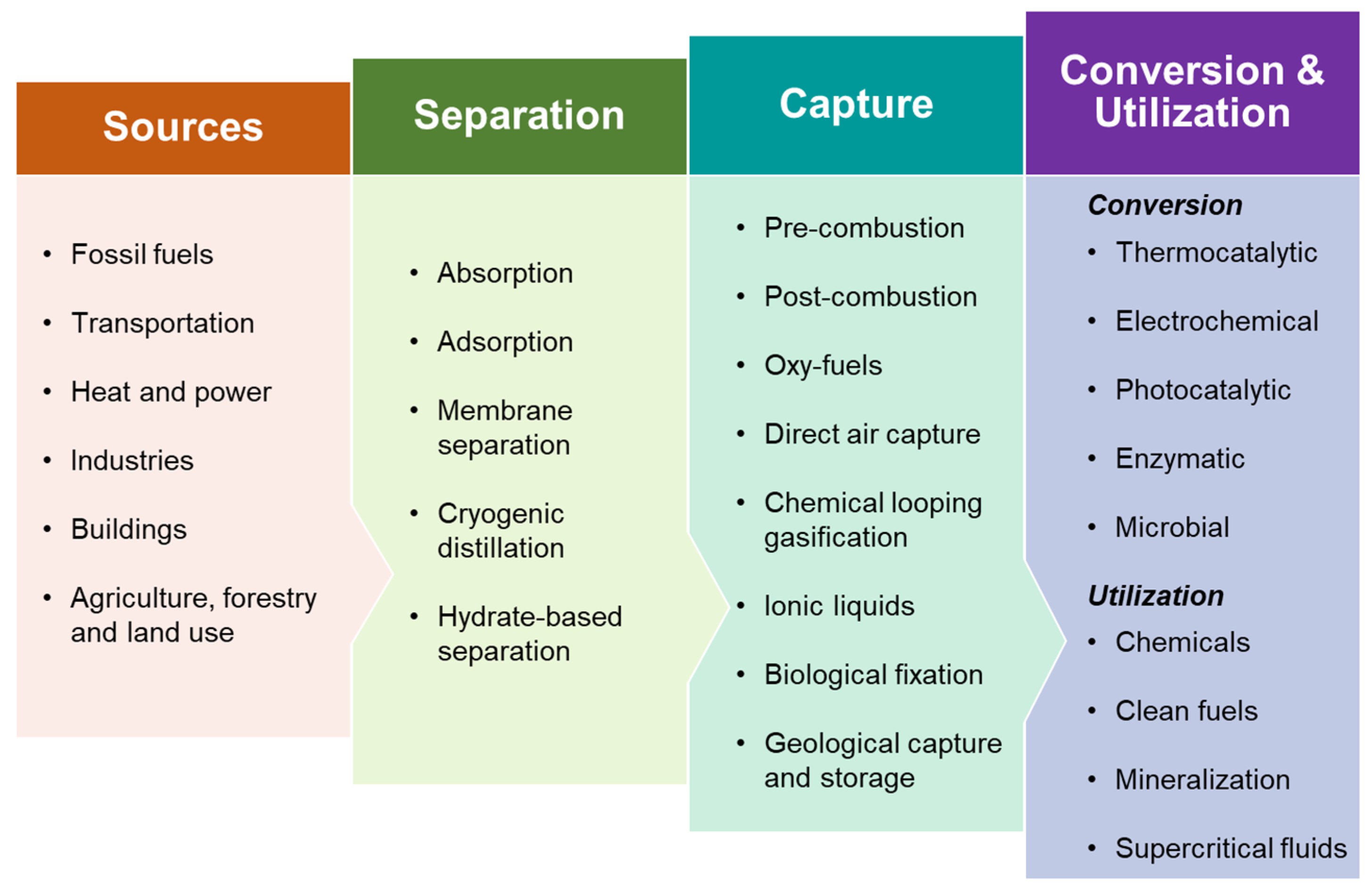
Carbon capture technologies play a pivotal role in curbing CO2 emissions, especially in light of the global push for net-zero by 2050 [3]. Figure 1 presents the key pathways involved in CO2 capture and utilization. The primary approaches for capturing CO2 include pre-combustion, post-combustion, oxy-fuel combustion, and direct air capture. Technologies currently employed for CO2 capture encompass absorption, adsorption, membrane separation, chemical looping, cryogenic distillation, and hydrate-based methods. Once captured, CO2 can be used in the production of clean fuels, chemicals, and valuable minerals, as well as in enhanced oil recovery and various other direct applications [4]. Pre-combustion, post-combustion, and oxy-fuel combustion are the three principal routes for carbon dioxide (CO2) capture in fossil-fuel-based systems. In pre-combustion capture, fossil fuels such as coal are gasified to produce a synthesis gas (syngas) consisting mainly of hydrogen (H2) and carbon monoxide (CO). The CO is then converted to CO2 via the water–gas shift reaction, and the CO2 is separated before combustion, enabling hydrogen to be used for power generation or industrial processes. This approach is most commonly integrated into integrated gasification combined cycle (IGCC) systems and offers a high concentration of CO2 for efficient separation, though it is limited by complex infrastructure and lower retrofit flexibility [3,5]. In oxy-fuel combustion, air is separated into oxygen and nitrogen using an air separation unit (ASU), and combustion occurs in a pure oxygen environment. This produces a flue gas composed primarily of CO2 and water vapor, making CO2 separation more straightforward. While oxy-fuel systems can achieve high CO2 purity, they require substantial energy input for oxygen production and gas compression, which increases overall costs [6]. Post-combustion capture involves removing CO2 directly from the flue gases after combustion, typically using chemical solvents like amines. This method is highly compatible with existing power plants and is considered the most mature capture technology; however, it suffers from a high energy penalty due to solvent regeneration and the low concentration of CO2 in flue gases [7]. Each of these technologies has distinct advantages and challenges. Pre-combustion offers high CO2 concentration but requires significant process modification; post-combustion is retrofit-friendly but energetically demanding; and oxy-fuel combustion provides nearly pure CO2 but involves high capital and operational costs.
Absorption, especially using chemical solvents like monoethanolamine (MEA), is the most commercially mature CO2 capture method. It involves the chemical reaction of CO2 with solvents and is widely used in post-combustion systems. Despite its high capture efficiency, absorption suffers from significant drawbacks including high regeneration energy, solvent degradation, and corrosion issues. Recent research explores alternative solvents such as ionic liquids and deep eutectic solvents to overcome these challenges [3]. Adsorption-based capture employs porous solid materials to physically bind CO2. It offers advantages such as lower energy demand and easier regeneration compared to absorption. However, performance can be limited under high humidity, and cyclic stability of adsorbents remains a concern [8]. The studies have focused on hybrid adsorbents and surface modification techniques to enhance CO2 selectivity [9]. Membrane technology separates CO2 based on differences in gas permeation rates. It is compact, modular, and energy-efficient under the right conditions, making it attractive for both pre- and post-combustion systems. However, issues such as low CO2 selectivity, pressure requirements, and membrane fouling limit large-scale application [10]. Mixed-matrix membranes and facilitated transport membranes are being developed to improve performance [11]. Chemical looping uses metal oxides as oxygen carriers in a cyclic redox process, producing a concentrated CO2 stream without nitrogen dilution. It inherently separates CO2 during combustion and reduces the energy penalty associated with separation. While promising for combustion-based systems, it requires further development in terms of reactor design and long-term material stability [12]. Cryogenic separation cools gas streams to very low temperatures to condense CO2. This method provides high-purity CO2 and is particularly suitable for gas streams with high CO2 concentration. However, it is highly energy-intensive and is generally more feasible in niche applications such as natural gas processing or direct air capture systems [13]. Hydrate-based separation is an emerging technology which captures CO2 through the formation of gas hydrates. It is considered environmentally friendly and selective, but practical implementation is still limited due to slow formation kinetics and high pressure requirements [14].
Hydrogen is an important energy carrier for power production and a variety of other industrial applications. Hydrogen-based technologies have recently gained popularity due to the global emphasis on environmentally friendly procedures. Hydrogen possesses the capacity to serve as the main energy carrier, mostly because of its utilization in fuel cell technology, which is gaining worldwide recognition as a viable substitute for mobile transportation [15,16]. The future general acceptance of hydrogen will mostly hinge on its production cost. A substantial decrease in generating costs will strongly facilitate the ongoing growth and advancement of the hydrogen-powered markets [17].
Process intensification (PI) is a popular topic that has received much recent attention. According to Stankiewicz and Moulijn [18], PI refers to “any chemical engineering development that leads to a substantially smaller, cleaner, and more energy efficient technology.” Stankiewicz and Moulijn [18] identify two primary areas of PI: process intensifying equipment and process intensifying strategies. The integration of different activities (such as reaction and separation) into a single unit, as a method of intensification, is a highly effective instrument for enhancing the efficiency of the current process, reducing energy usage, and minimizing the production of unwanted outputs or byproducts. By providing substantial advancements in process technology over a wide range of parameters, this intensification has the potential to increase both the efficiency of the process and the economics of the process. [19,20]. Typically, reports in the literature categorize processes into three approaches: unit operations, functions, and phenomena. According to the literature, the phenomenon method is considered the most effective of the three ways stated above. This is because it allows for the achievement of PI’s key objectives by enhancing phenomena. Furthermore, understanding the phenomenon at a fundamental level has the benefit of directly leading to the creation of mathematical model equations. These equations are essential for systematic and efficient process design and synthesis. PI’s fundamental principles include the integration of operations, functions, and phenomena, as well as the focused augmentation of a specific phenomenon within a given operation [18,19].
PI uses a variety of strategies (adsorption, absorption, and membranes) to achieve this intensification. Adsorptive reactors (ARs) and membrane reactors (MRs) are particularly well known for their ability to remove and recover generated gases from fuel gas. Adsorbents and membranes selectively eliminate reaction products such as H2 and CO2, shifting the equilibrium to the product side, enabling the coupling of higher conversions and gas capture procedures in a single phase. Adsorption reactors (ARs) and membrane reactors (MRs) are successful and promising approaches for attaining intensification in the simultaneous production, separation, and purification of products, as discussed earlier. The principles of process intensification (PI) are implemented in ARs and MRs through the integration of reactor-membrane units (Principle 1), the integration of conversion and separation processes (Principle 2), the integration of reaction–diffusion phenomena (Principle 3), and the focused enhancement of a specific reaction phenomenon (Principle 4). The ability to operate at lower reaction temperatures, the reduction in material costs, the increase in operational safety, the elimination of the requirement for excess steam in the reaction, the minimization of the requirement for downstream purification—these technologies have several additional remarkable characteristics, one of which is the reduction in the quantity of catalyst that is required to achieve the appropriate level of conversion. However, systems based on MRs or ARs can only collect one of the reaction’s products, such as carbon dioxide or hydrogen gas, while the integrated separation of the reaction’s products produces synergy. This synergy considerably increases the efficiency of the process by boosting reaction speeds, yields, and selectivity [18,19].
The goal of this research is to offer evidence demonstrating the feasibility of process intensification, and to model and simulate a hybrid intensified adsorptive-membrane reactor (HAMR) process for simultaneous carbon capture and hydrogen production. A complete, multi-scale, multi-phase, dynamic, computational fluid dynamics (CFD)-based process model is developed, quantifying the numerous underlying complicated physicochemical phenomena happening at the pellet and reactor scales. Model simulations are then run to determine the impact of dimensionless variables on overall system performance and to acquire a better understanding of the cyclic reaction/separation process.
2. HAMR System
2.1. Design of the HAMR
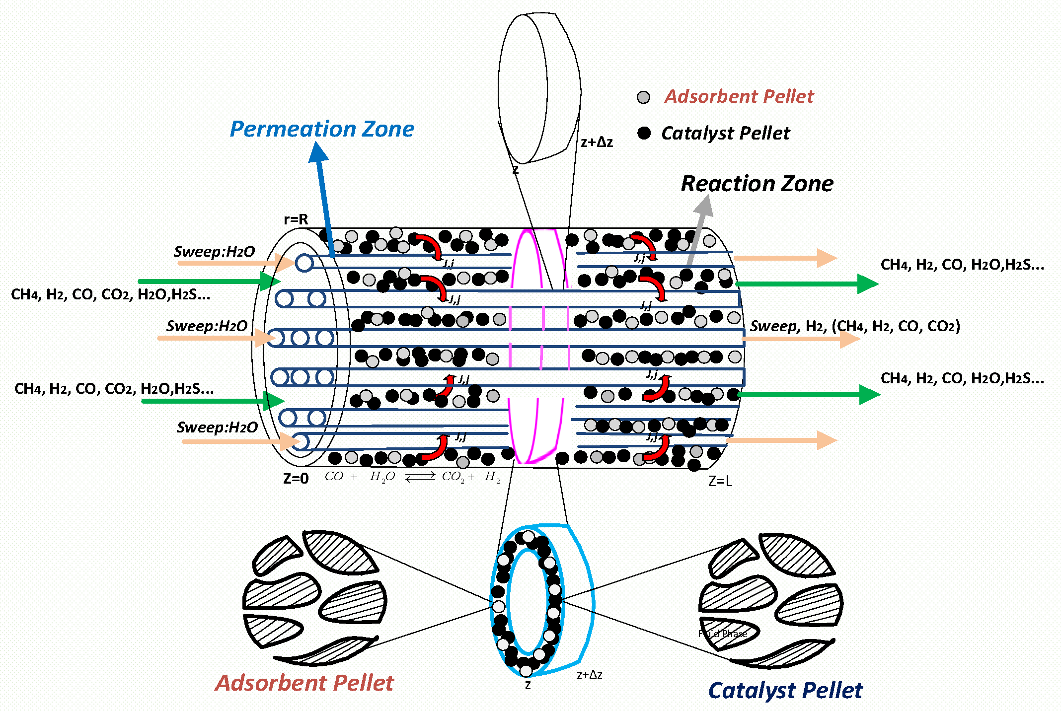
The reaction–adsorption and permeation zones constitute the HAMR. The reaction–adsorption zone consists of the catalyst-pellet, adsorbent-pellet, and bulk gas phase domains, situated between the internal wall of the HAMR module and the external surfaces of the membrane tubes. The HAMR module, illustrated in Figure 2, comprises 85 membrane tubes, each with an inner diameter of 3.5 mm, an outer diameter of 5.7 mm, and a length of 1 m. The combination of these HAMR modules in parallel and series configurations yields an industrial-scale HAMR unit. An industrial-scale HAMR unit typically comprises around 1000 HAMR modules. In the HAMR, concurrent reaction–separation processes occur. The process consistently eliminates reaction products from the bulk gas phase, utilizing a membrane tube for the selective removal of H2 and an adsorbent for the selective removal of CO2. A sweep gas, specifically steam in this study, flows either co-currently or counter-currently to the reacting mixture in the permeation zone, facilitating the removal of hydrogen.
The HAMR system could implement a versatile syngas clean-up and multi-product production system, reduce greenhouse gas (CHG) capture and disposal costs, minimize capital and operating costs, and maximize profitability by increasing power generation capacity. Compressing CO2 is a major energy consumer for carbon capture systems. Traditional methods create a pure CO2 stream at 1 pressure, which must be compressed to 150 bar for sequestration or use. This compression stage uses a large amount of power plant power. The HAMR operates at pressures above 20 bar, near to the power plant gasifier’s operational pressure. High pressures cause the HAMR to release pure CO2, conserving energy.
Other economic benefits of the suggested method are also considerable. Benefits include lower operating temperatures, steam needs, catalyst usage, and pure product streams. The HAMR system uses low-temperature water gas synthesis (WGS) catalyst to operate at lower reaction temperatures. This removes high-temperature operation and catalyst, reducing material waste and improving process safety. By breaking equilibrium conversions in traditional HTSR + LTSR sequences, the HAMR approach uses less catalyst and steam than the conventional procedure. The suggested HAMR method generates H2 and CO2 with purity above 95%. These points prove that the proposed approach outperforms the present CCS technology in costs, environment, and power generation.
2.2. Integration of the HAMR System in the Power Generation Process
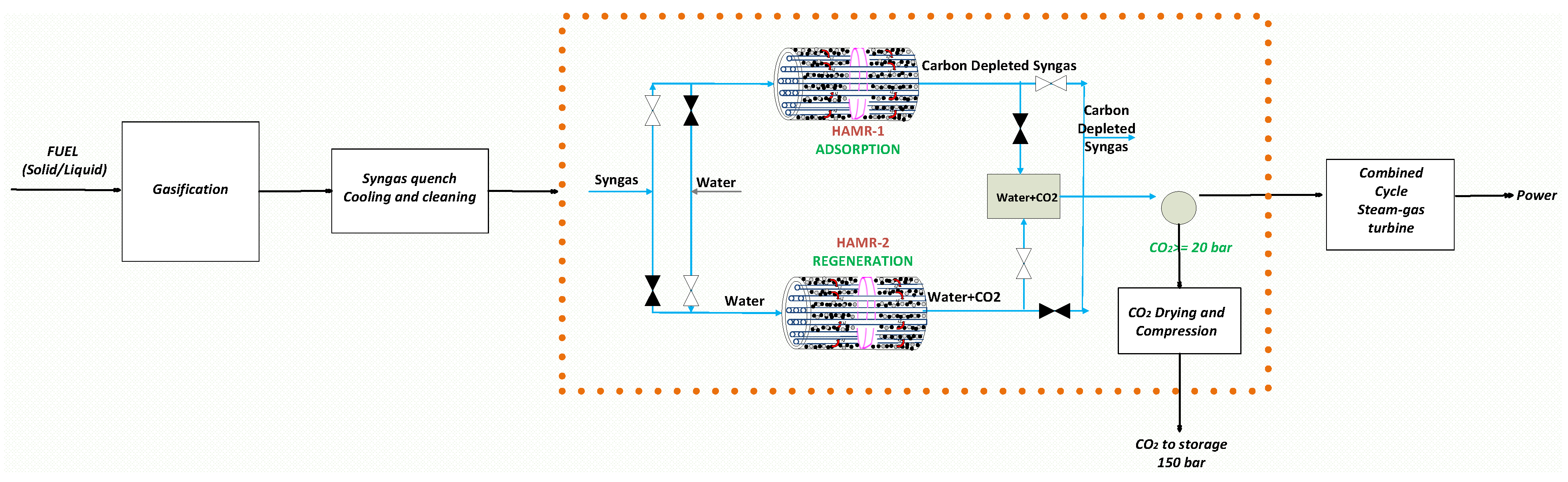
An integrated gasification combined cycle (IGCC) power plant converts fuel into syngas through a high-pressure gasifier, utilizing steam and oxygen in the process. The process gas stream transitions from the reformer system to the adiabatic two-stage water gas shift reactor system. In industrial applications, water gas shift reactors consist of two temperature stages: the high-temperature shift reactor (HTSR) and the low-temperature shift reactor (LTSR), with a cooling process recommended between them for hydrogen production. This system (HTSR + Cooling + LTSR) facilitates enhanced CO conversion rates and optimal hydrogen production levels. CO2 emissions from power generation in integrated gasification coal power plants (IGCC) are a major concern. Existing CCS (carbon capture and storage) technology necessitates more energy and results in a 15–20% reduction in efficiency in IGCC power plants that incorporate CO2 capture [20]. This work presents a new hybrid alternative process (HAMR), shown in Figure 3, as a very effective substitute for conventional pre-combustion CCS technology. The HAMR system generates a stream highly concentrated in hydrogen for power production and a stream of pure, high-pressure CO2 for sequestration. The stream with a high concentration of hydrogen is then utilized in a heat and power generation unit, therefore generating energy that suits the desired performance characteristics. This procedure exhibits promising prospects for achieving high efficiency and ultra-compact manufacturing.
2.3. Modeling of the HAMR
Physically, the HAMR is a complex system that includes many process functions in different areas of the device, operating at many scales and throughout many phases. The HAMR modeling incorporates two distinct scales: the microscale, which takes into account catalyst/adsorbent pellet-scale characteristics such as average pore size, reaction/adsorption rates, material properties, and shape; and the macroscale, which takes into account reactor scale features such as membrane module dimensions, membrane tube characteristics, and catalyst/adsorbent packing void fraction. As the HAMR configuration investigated here does not include catalyst or adsorbent pellets, the permeation zone is considered purely at the macroscale level. Within the multi-scale method, the HAMR system is represented as distinct domains and sub-domains, enabling a thorough evaluation of the individual contributions of their parameters to the full system. The catalyst-pellet, adsorbent-pellet, bulk gas phase in the reaction zone, and bulk gas phase in the permeation zone are regarded as distinct domains. However, the solid and fluid phases within the catalyst/adsorbent pellet are included as sub-domains. Separate applications of the Reynolds transport theorem (RTT) are used to derive conservation equations for each of these domains and sub-domains. Using the finite element technique (FEM), the time-dependent equations obtained are applied in the COMSOL 5.2 software package and solved simultaneously in all three domains along the length of the HAMR.
The catalyst and adsorbent pellet domains along the reactor axis provide source terms to reactor domain equations and receive reactor gas conditions at the pellet boundary. Indeed, pellet boundary information is needed to solve differential equations describing system behavior in the pellet interior. However, solving the differential equations representing reactor internal system behavior requires knowledge of the pellet boundary source term. The catalyst- and adsorbent-pellet domains receive gas pressure, temperature, velocity, species concentrations, and flux information from the reactor domain. The differential equation system is solved simultaneously. After this process, temperature, pressure, and species profiles are known at each reactor domain axial location and pellet domain radial, and the reactor domain axial local pair.
Instantaneous effectiveness factors measure the effects of transport and reaction (catalyst pellet) and sorption (adsorbent pellet). They are ratios of the catalyst/adsorbent pellet’s actual uptake rate (due to combined transport and reaction or adsorption) of a given species over the same uptake rate without transport limitations, i.e., when the particle’s gas phase concentration matches that at the pellet’s surface. The derivation of the model’s equations incorporates geometrical parameters such as volumetric porosity , area porosity , and the area-to-volume factor . In order to enhance spatial integration during the formulation of a comprehensive mathematical model, a differential volume associated with each phase is linked to a differential volume of the corresponding system. In the context of the catalyst pellet, this relationship establishes the concept of volumetric porosity, whereas the volumetric void fraction is applied in the context of the reactor. In a similar manner, for the surface integration within a multi-phase system, the same methodology can be employed to establish a correlation between the differential area occupied by each phase and the corresponding differential area of the system. This allows for the determination of area porosity and area void fraction for both the pellet and reactor systems, respectively. The catalyst pellet, adsorbent pellet, reactor domain, and permeation domain are denoted by the superscripts , , , and . The catalyst and adsorbent pellets and reactor domains composed by solid or fluid phases, are identified by the subscripts and , respectively. The symbols and represent phases and domains, respectively.
2.3.1. Model Assumptions and Justification
The model’s construction accounted for the following main assumptions. (1) One-dimensional axial model: Justified by the tubular geometry and dominant axial gradients, radial non-uniformities are assumed to be negligible due to small diameter and efficient mixing from high-pressure flow, consistent with standard design assumptions in multi-tubular reactors. (2) Isotropic, homogeneous catalyst and adsorbent pellets: These were chosen for computational feasibility and based on the use of commercially available structured packing materials with consistent pore size and particle shape distributions. (3) Constant physical properties such solid densities, void fractions, surface areas, diameters, etc., are used in the construction of the model. (4) Neglecting axial conduction and dispersion in pellets: This assumes dominant convective transport at the reactor scale and low Biot numbers in the pellet domains, which validate the use of intraparticle diffusion resistance as the primary transport limitation
In the pellet domain boundaries and at the pellet surface, concentration and temperature continuity is enforced by coupling pellet equations to reactor domain values at the interface. At the pellet center (symmetry), zero gradient (Neumann condition) is applied, reflecting spherical or cylindrical symmetry. In the reactor domain boundaries, Dirichlet conditions (at the inlet) with specified inlet velocity, temperature, and species concentrations based on the syngas feed composition were considered. Convective (Danckwerts-type) conditions, allowing species and thermal profiles to freely exit without artificial backflow effects, were considered in the outlet.
2.3.2. Dimensionless Variables
Dimensionless numbers are crucial in the design of engineering applications. These numbers possess a pragmatic physical significance derived from transport phenomena such as mass, heat, and momentum. Their magnitude quantifies the relative scale between these phenomena. There exist two methods for deriving dimensionless numbers from dimensional analysis: classical dimensional analysis and discriminating dimensional data. The latter distinguishes between the dimensions of space and the components of a variable, resulting in an increased number of variables. Consequently, according to the Pi theorem, a reduced number of dimensionless numbers is obtained. This method has been used to both free convection and mixed convection phenomena. Non-dimensionalization of the differential equations that drive the phenomena, employing reference quantities that enable the definition of dimensionless variables, is an alternate method for producing dimensionless coefficients [21,22]. First, we establish the dimensionless variables as follows. The equations of the model for the scales of pellets and reactors are expressed in use of dimensionless variables.
Catalyst/adsorbent pellet-scale:
Reactor scale (Reaction zone):
Reactor scale (Permeation zone):
2.3.3. Molar-Based Catalyst/Adsorbent Pellet-Scale Model Equations
The final component mass, energy, and momentum conservation equations of the catalyst and adsorbent pellets, established using the RTT method, may be stated as follows:
Component mass conservation:
Adsorbent Pellet Fluid:
Catalyst Pellet Fluid:
Energy conservation:
Adsorbent Pellet Fluid:
Catalyst Pellet Fluid:
The initial and boundary conditions for solving the conservation equations are expressed as follows:
Initial Conditions:
Boundary Conditions:
2.3.4. Molar-Based Reactor-Scale (Reaction Zone) Model Equations
The RTT-based final component mass, energy, and momentum conservation equations for the reactor domain can be written as follows:
Component mass conservation:
Reactor–Fluid:
Momentum conservation:
Energy conservation:
Reactor–Fluid:
Initial and boundary conditions for reactor-scale model equations
The initial and boundary conditions for the solution of the conservation equations are as follows:
Initial Conditions:
Boundary Conditions:
2.3.5. Molar-Based Reactor-Scale (Permeation Zone) Model Equations
The final mass, energy, and momentum conservation equations of the permeation zone in the reactor domain can be stated as follows:
Component mass conservation:
Momentum conservation:
Energy conservation:
Initial and boundary conditions for permeation zone model equations
The initial and boundary conditions for the solution of the conservation equations are shown as follows:
Initial Conditions:
Boundary Conditions:
3. Results and Discussion
A syngas with the composition H2:CO:CO2:N2:CH4:H2S:H2O = 0.51:1.00:0.36:2.28:0.1:0.0031:1.5 is used as the feed for the HAMR. In the simulations conducted under the adiabatic scenario, the HAMR was assumed to function at a temperature of 250 °C and a pressure of 25 bar. Within the simulations, the membrane permeances (m3/m2·h·bar) were assumed to be as follows: H2 = 1, CO = 0.0027, CO2 = 0.0018, CH4 = 0.0027, H2O = 0.333. These are representative of the values we typically observe with CMS (carbon molecular sieve) membranes of superior quality. The values shown in Table 1 pertain to a commercially available Co-Mo/Al2O3 shift catalyst and a hydrotalcite adsorbent. The rate constant is derived from reference [19], while the adsorption parameters were determined by fitting against experimental data. Further information concerning all facets of the modeling, including kinetic parameters for membrane permeation and carbon dioxide adsorption, can be located in the author’s previous publications and other publications concerning multi-scale membrane reactor modeling and multi-scale adsorptive reactor modeling [17,23,24]. Additionally, the validation of the developed multi-scale model using experimental data is documented in the author’s previous publications [23,24].
3.1. Effectiveness Factor Evaluation for Both Catalyst and Adsorbent Along the HAMR Reactor Length
This section illustrates the significance of local, pellet-scale behavior in influencing overall process behavior by quantifying the effectiveness factors of catalysts and adsorbents in the HAMR. The temporal effectiveness factor for the ith species is defined by Equation (20); the superscript refers either catalyst or adsorbent pellet.
Similarly, the length-averaged effectiveness factor is given by Equation (21):
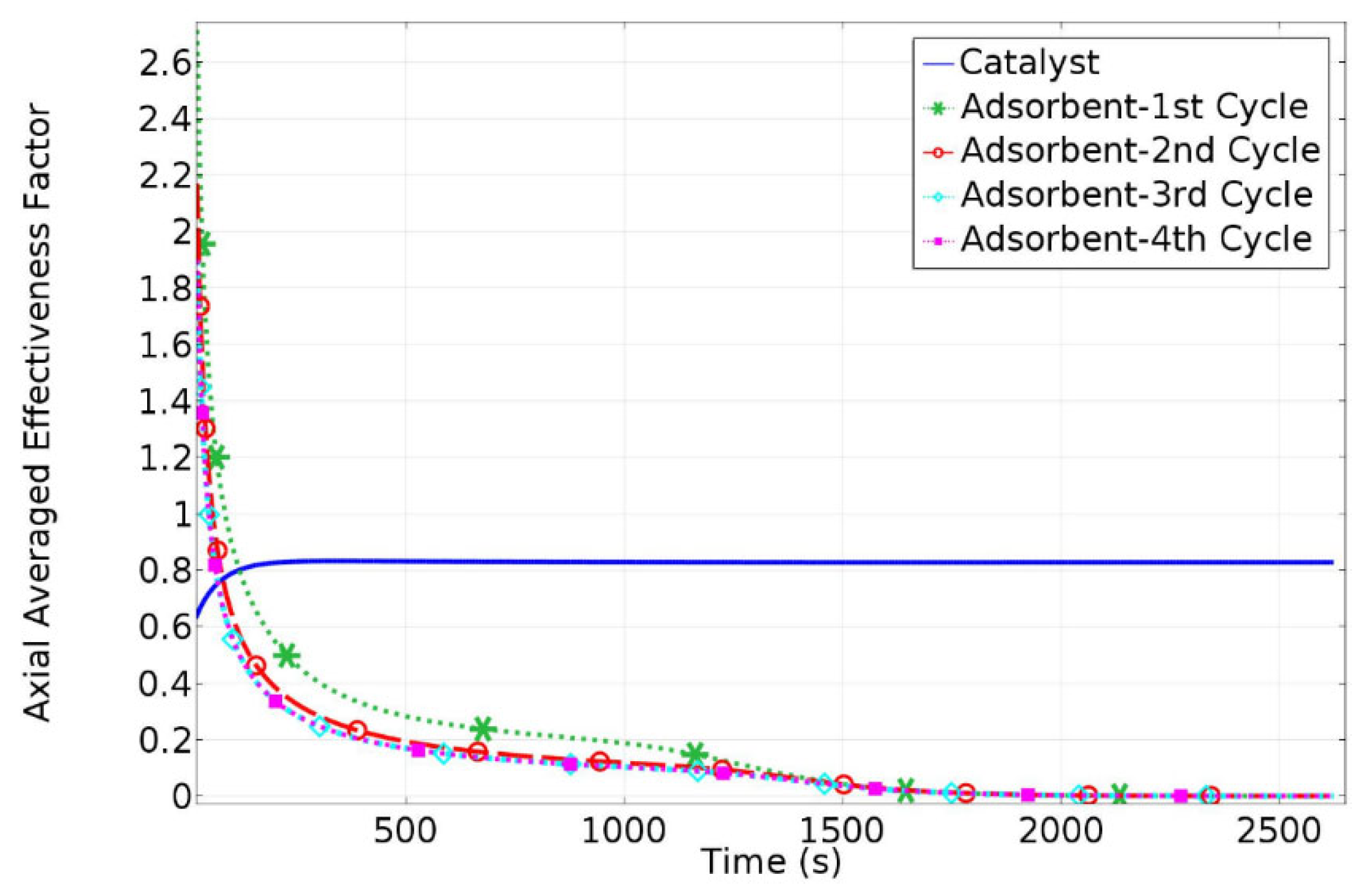
Figure 4 shows the HAMR axially averaged catalyst and adsorbent effectiveness factor profiles. The axially averaged effectiveness factor profiles of the adsorbent pellet for each of the four consecutive HAMR working cycles shown approach zero in around 1800 s, indicating adsorbent saturation. During the HAMR desorption step, the produced CO2/H2O gas mixture (at 723 K and the same pressure as the adsorption step) is separated at the same pressure as the reactor exit, and the separated high-pressure H2O is recycled in the desorption step rather than being compressed repeatedly. The HAMR catalyst effectiveness factor, on the other hand, increases over time and reaches an asymptotic value in around 200 s, when the HAMR begins to transition into a PBR mode of operation.
3.2. Compressor Power Requirement vs. HAMR Exit Pressure
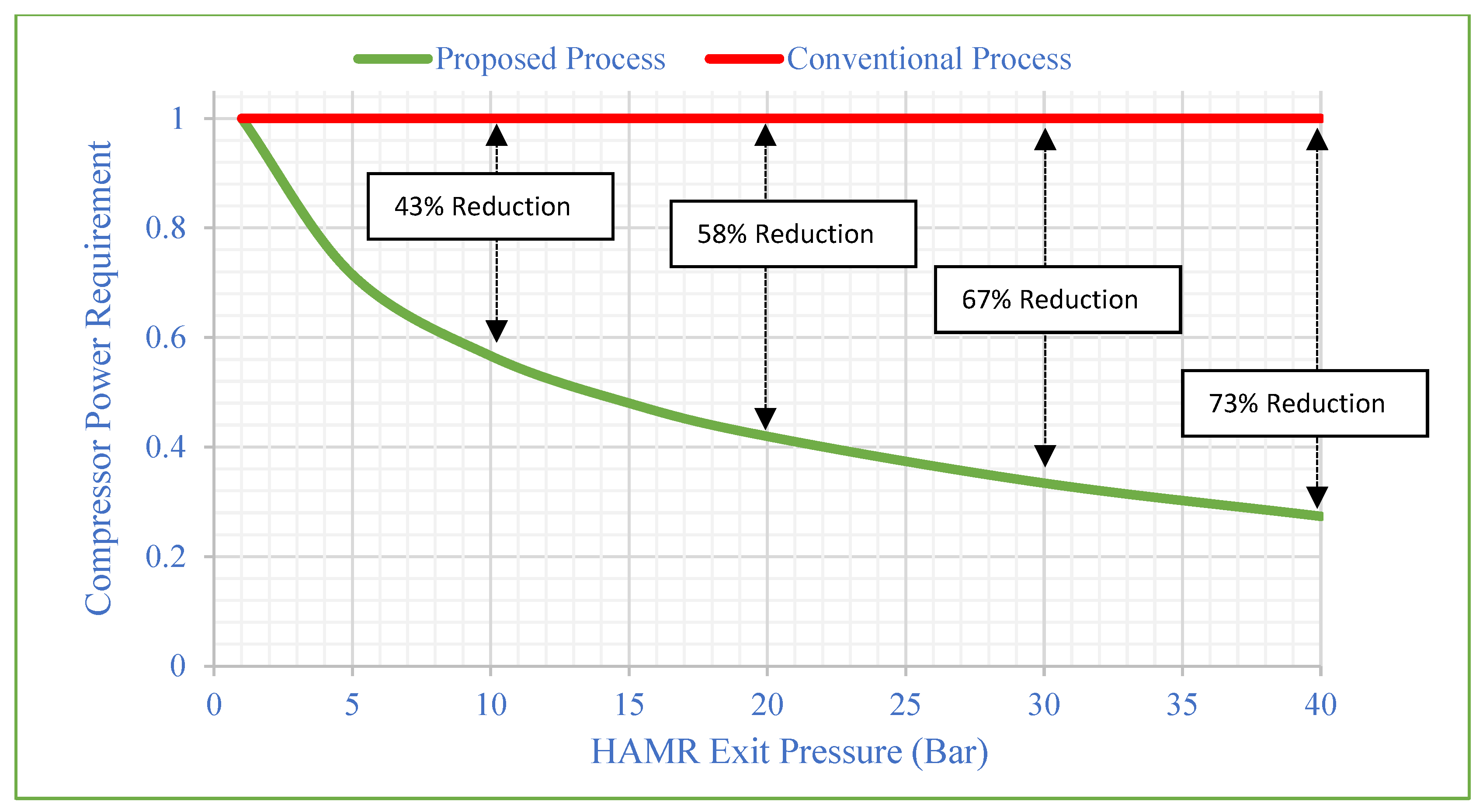
A significant benefit of the proposed process is its diminished energy usage relative to the traditional method that uses a dual-stage Selexol unit for the separation of carbon dioxide from the syngas produced by the WGSR. The traditional method produces a pure CO2 stream at around 1 bar, which subsequently requires compression to approximately 150 bar for sequestration or use. This compression phase utilizes a substantial amount of the energy generated by the power plant. Conversely, the AR functions at significantly elevated pressures (>20 bar), comparable to the operational pressures of the power plant’s gasifier, reformer, or pyrolyzer, and inherently provides a clean CO2 stream at these higher pressures, so achieving considerable energy savings.
The ideal CO2 capture and sequestration (CCS) system must operate safely, reliably, and cost-effectively. The most cost-effective conditions for transporting and storing significant amounts of CO2 across intermediate distances are achieved when the CO2 is in the liquid or supercritical regime. Thus, CO2 compression is a critical stage in the advancement of carbon capture and storage technologies. The cumulative efficiency of the selected compressor system is heavily influenced by the variables of individual compressor efficiency, pressure ratio, and inlet temperature/pressure. There are several compressor systems available to meet these compression service requirements, depending on inlet and exit pressures and volumetric flows. In this study, four compressor sections with three intercoolers are used (Figure 5), and the individual efficiency of the multi-stage compressor is set at 84%, 80%, 76%, and 72%, respectively. Figure 6 depicts the comparative compressor power requirements of two processes (conventional and suggested). Figure 6 depicts the compressor power demand as 1 for the conventional process, and power reductions are determined for the proposed system based on the HAMR outlet pressure. The CO2/water mixture is acquired during the HAMR desorption process, and the stream is dried at the same pressure. Finally, the compression procedure begins by using the HAMR’s exit pressure as the beginning pressure for the compressor system. Varying the intake compressor pressure (or HAMR exit pressure) from 10 to 40 bar reduces the power demand by approximately 43–72%.
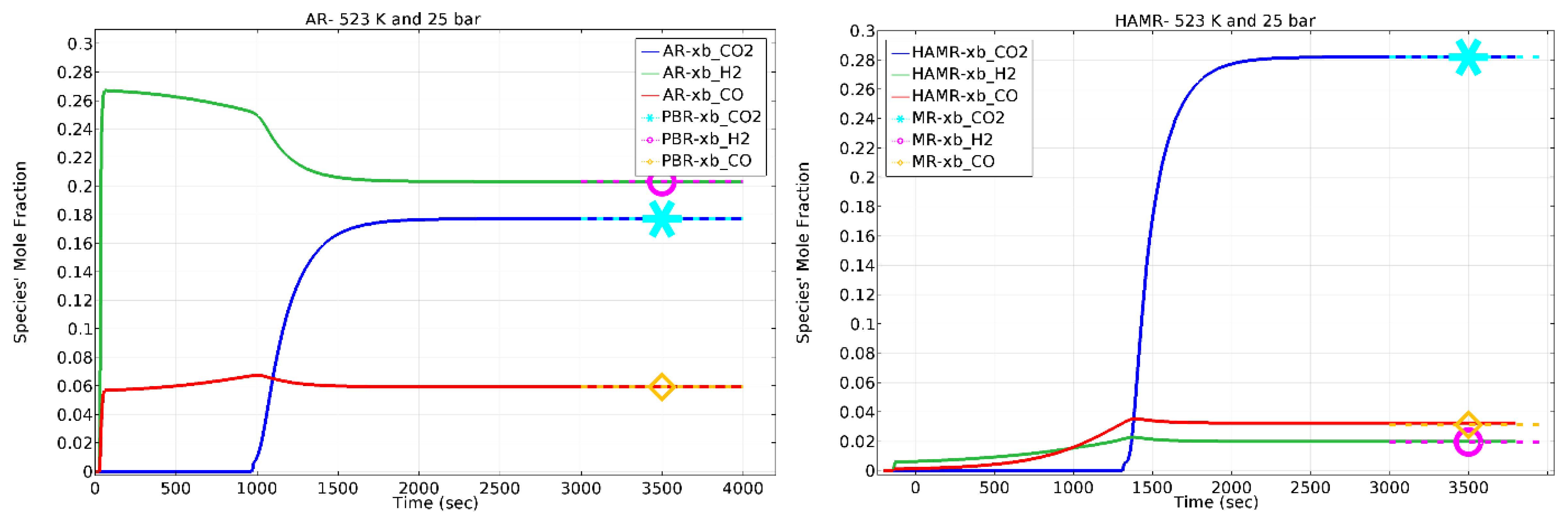
3.3. Comparison and Analysis of Species Mole Fractions in the HAMR, AR (Adsorptive Reactor), MR (Membrane Reactor), and PBR (Packed Bed Reactor) Configurations
Figure 7 displays the mole fractions of the AR (left) and HAMR (right) output species. As depicted in Figure 7 (left), the AR functions as a PBR once it reaches its maximum carbon loading capacity. Similar to an AR, the HAMR also manifests as an MR once it reaches its maximum carbon capture capacity.
3.4. CO Conversion, H2 Recovery, and CO2 Lost in the HAMR
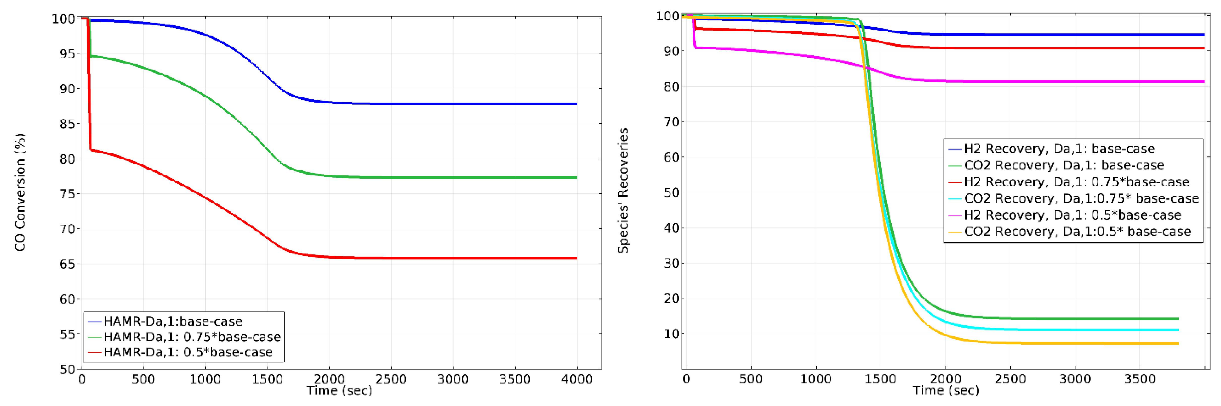
The HAMR achieves an average CO conversion of 93.66%, as shown in Figure 8 (left), and a steady-state conversion of 89% (which also includes the MR) for a period of 4000 s. Alternatively, Figure 8 (left) shows an average CO conversion of 69%, whereas steady-state conversion of 66% (also representing the PBR) is achieved in the AR system over a period of 4000 s. The results indicate that the HAMR has a remarkable superiority over ARs, MRs, and PBRs when subjected to identical conditions. The HAMR operates in two phases: reaction/adsorption and desorption. Thus, continuous functioning requires the use of at least two reactors. In step one, the syngas gas is fed into the first HAMR, which performs the WGS reaction and separates CO2-H2. While this is happening, the other HAMR is flushed with steam, and desorption occurs, resulting in a stream of CO2 and H2O. This characteristic provides excellent operational flexibility. For instance, this adaptability offers significant potential in terms of the duration of process operation. In contrast to operating the reactors’ system for 4000 s, operating for roughly 1000 s yields an approximate conversion of 93.66%. Therefore, this situation is more desirable than the first one.
Figure 8 (right) illustrates the H2 recovery (which is defined here as the molar flow rate of H2 exiting the MR permeate side divided by the total molar flow rate of H2 exiting the MR) and total CO2 lost (ending up) in the MR permeate side. As shown in Figure 8 (right), approximately 95% of H2 recovery is obtained in the HAMR by the effect of membrane separation. However, once the adsorbent reaches its full capacity, the membrane loses approximately 15% of the CO2. Again, using the cyclic HAMR system with a lower operational time will maximize CO2 recovery.
3.5. Effect of on CO Conversion, H2 Recovery, and CO2 Lost in the HAMR
The Damköhler numbers (Da) are dimensionless quantities employed in chemical engineering to establish a correlation between the timeframe of a chemical reaction (reaction rate) and the pace of transport phenomena unfolding in a given system. In fluid dynamics, Damköhler numbers are defined as the quotient of the reaction rate divided by the fluid’s global movement rate, or the ratio of reaction rate to diffusive transport across an interface in a multi-phase reaction. Different continuous reactive systems have shown that the conversion rate increases as Da increases. As a result, Da is a parameter that may be evaluated in various continuous reactive systems, geometries, sizes, and recirculation systems. Furthermore, a thorough examination of the Damköhler numbers and the conversion yields tools for reactor scaling-up [21,22,25].
The effect of on HAMR performance is shown in Figure 9. Decreasing the value of from the base-case to 0.5 × base-case reduces the conversion approximately 25%. Moreover, decreasing the value of from the base-case to 0.5 × base-case reduces the H2 recovery by approximately 15%, and the CO2 lost through membrane by approximately 45%. Optimal operating conditions for the HAMR depend on conversion and H2-CO2 recoveries. Simulation findings clearly indicate that operating the HAMR with the number having a specific magnitude guarantees these circumstances for 1000 s operating time.
3.6. Effect of on CO Conversion, H2 Recovery, and CO2 Lost in the HAMR
The effect of on HAMR performance is shown in Figure 10. Increasing the value of from the 0.5 × base-case to 2 × base-case increases the conversion approximately 23%. Increasing the value of from the 0.5 × base-case to 2 × base-case does not have significant effect on H2 recovery. However, it decreases CO2 loss by around 100%. Regarding conversion and H2-CO2 recoveries, simulation results unequivocally demonstrate that operating the HAMR with a number having a specific magnitude ensures the necessary operating conditions for a 1000 s operating time.
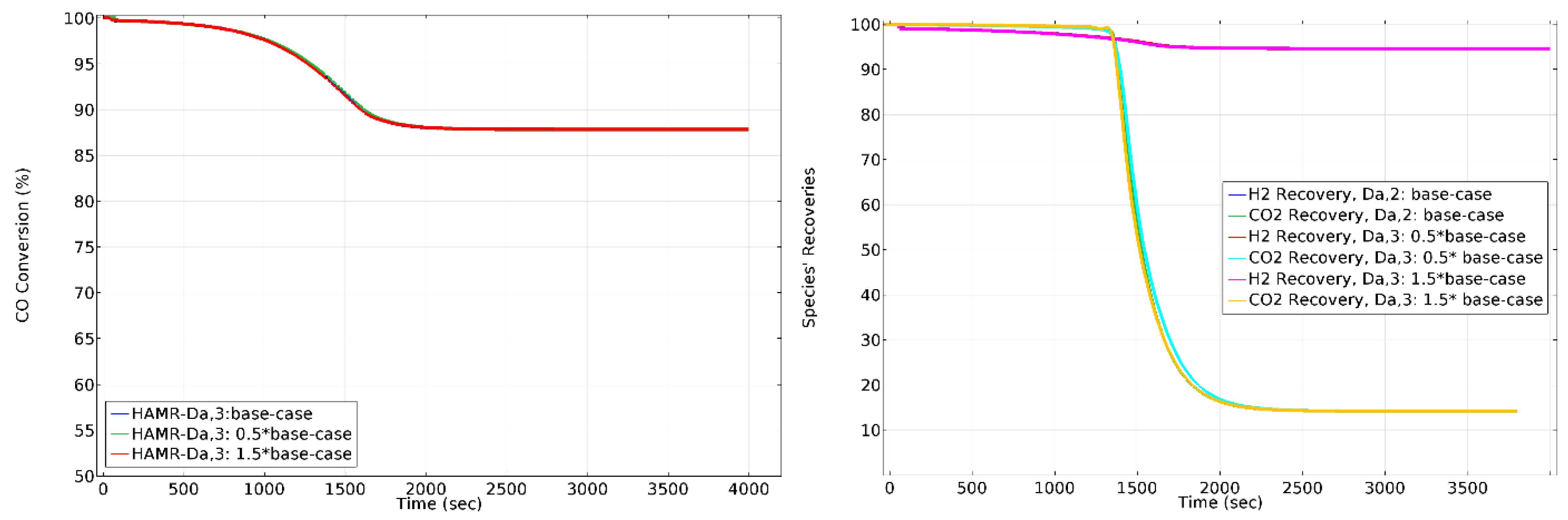
3.7. Effect of on CO Conversion, H2 Recovery, and CO2 Lost in HAMR
The effect of on HAMR performance is depicted in Figure 11. does not have a significant effect on HAMR performance.
3.8. Effect of on CO Conversion, H2 Recovery, and CO2 Lost in HAMR
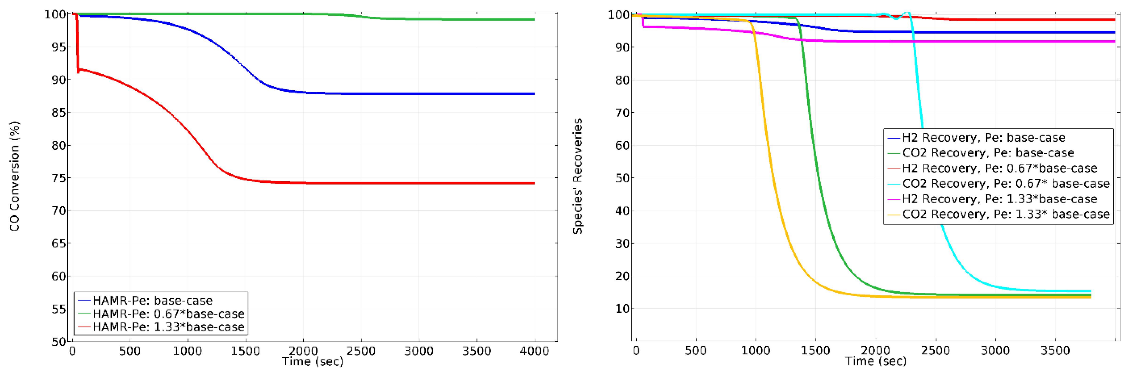
The Péclet number (Pe) correlates the overall velocity of the fluid to its rate of diffusive mass transport. Pe and Da represent reactors where diffusion, overall movement, and reaction rates of the species happen concurrently. The impact of on HAMR performance is illustrated in Figure 12. Raising the value of from 0.67 times to 1.33 times the base case results in approximately 25% conversion reduction. Raising the value of from 0.5 times to 2 times the base case does not significantly impact CO2 lost. Nevertheless, it reduces the H2 recovery by around 8%. Analogous to the and numbers, maintaining the Pe number at designated magnitudes guarantees the optimal operating conditions necessary to achieve process objectives of high conversions and product species recoveries.
3.9. Cyclic Behavior of the HAMR
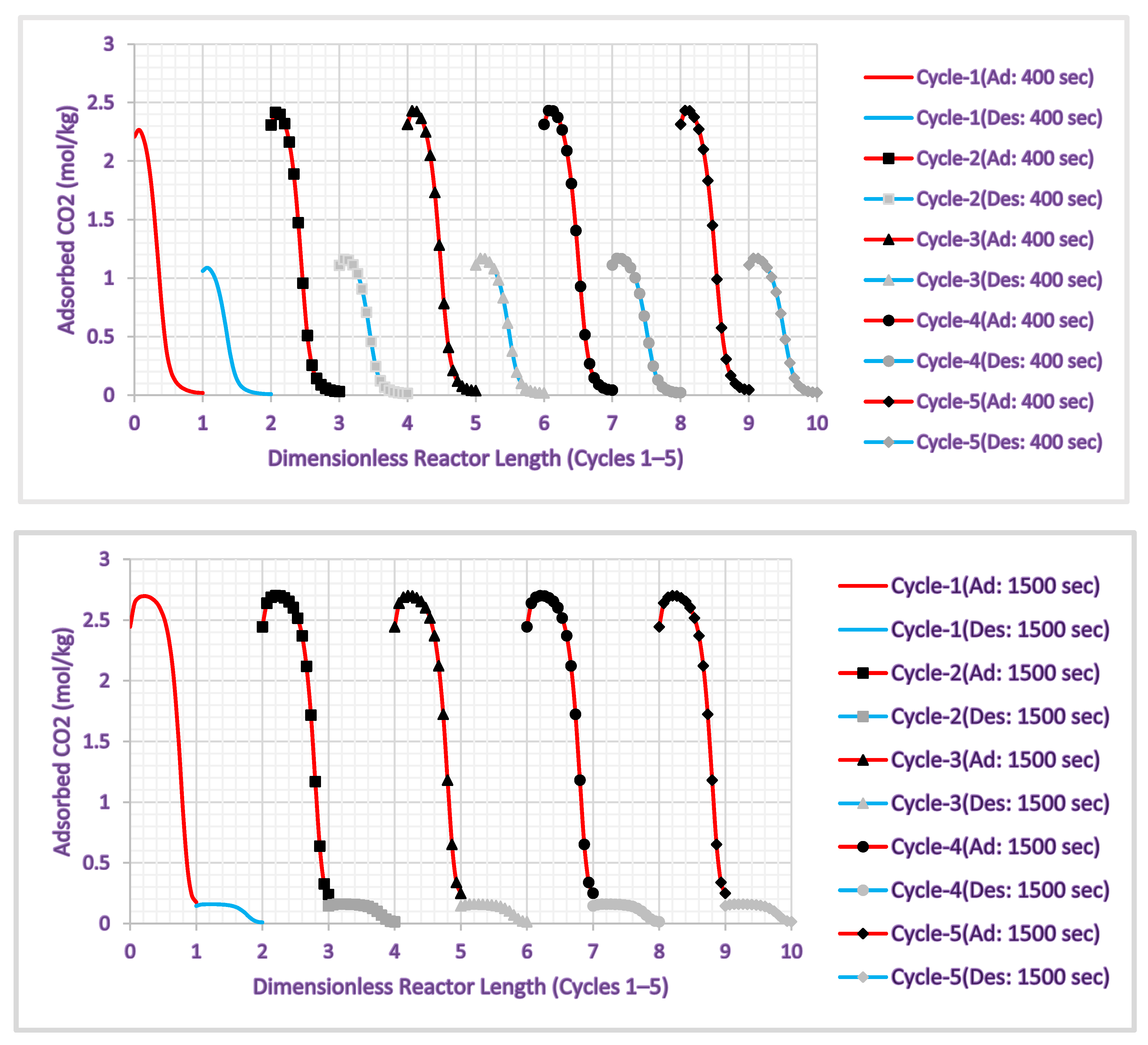
Figure 13 depicts the AR CO2 loading axial profiles throughout the [0, 1] and [1, 2] x-axis intervals during the adsorption and desorption phases of the HAMR’s first operational cycle at switch times of 400 s and 1500 s. Accordingly, [2, 3] and [3, 4] denote the second cycle; [4, 5] and [5, 6] signify the third cycle; [6, 7] and [7, 8] indicate the fourth cycle; and [8, 9] and [9, 10] reflect the fifth cycle. Figure 13 illustrates the HAMR reactor operating under steady-state conditions during the fourth cycle at time intervals of 400 and 1500. The quantity of adsorbed CO2 in each adsorption/desorption cycle stabilizes at a fixed value by the fourth cycle. Consequently, our findings indicate that the HAMR can be run cyclically at any appropriate operating duration.
3.10. Sustainability Assessment (HAMR vs. Conventional Process, HTSR + LTSR)
Table S1 (Supplementary Materials) delineates the sustainability indicators employed in this study for the HAMR and HTSR + LTSR. Table S1 includes measures pertaining to the economic, energy, environmental, and material efficiency aspects of sustainability to evaluate sustainable performance levels. The subsequent sustainability scale converts each indicator score into a dimensionless format for every indicator:
where i indicates the indicator ().
Figure 14 presents measurements of all indicators for HAMR/(HTSR + LTSR) and illustrates the percentage enhancement in sustainability of the HAMR compared to the conventional HTSR + LTSR design. The present state of these assumptions indicates no enhancements in sustainability for indicators 1, 2, 3, 12, and 14. In contrast, the HAMR provides significant sustainability improvements ranging from 35% to 138%. The average sustainability improvement for the HAMR compared to the conventional HTSR + LTSR design is approximately 57%, indicating that the sustainability assessment demonstrates substantial advantages of the HAMR over the HTSR + LTSR.
4. Conclusions
This paper presents an analysis of the process intensification potential, model, and simulation of HAMR (hybrid intensified adsorptive-membrane reactor) for the simultaneous capture of carbon and production of hydrogen. The analysis is applied to a power generation process, namely an integrated gasification combined cycle (IGCC) power plant. A very detailed, multi-scale, multi-phase, dynamic process model based on computational fluid dynamics (CFD) is developed. This model accurately measures the many intricate physicochemical processes that take place at both the pellet and reactor levels. The overall performance of the system is investigated, and a deeper understanding of the cyclic reaction/separation process is obtained by conducting model simulations to analyze the influence of dimensionless variables.
The proposed designs improve the sustainability of the base-case process substantially by having the simultaneous achievements of higher CO conversions (close to full conversion) and higher process product (hydrogen and carbon dioxide) recoveries and purities. The results indicate that the hybrid system shows a steady-state cyclic behavior to ensure flexible operating time. A sustainability evaluation was conducted to illustrate the sustainability improvement in the proposed process compared to the traditional design. The results indicate that the integrated–intensified adsorptive-membrane reactor technology enhances sustainability by 35% to 138% for the chosen 21 indicators. The average enhancement in sustainability is almost 57%, signifying that the sustainability evaluation reveals significant benefits of the integrated–intensified adsorptive-membrane reactor process compared to HTSR + LTSR.
In this work, the importance of dimensionless numbers, such as the Damköhler and Péclet numbers, in the design of engineering applications has been demonstrated. The numbers have a practical physical meaning deduced from transport phenomena including mass, heat, and momentum. Their numerical value measures the comparative scale of these phenomena. Hence, the Damköhler and Péclet numbers are valuable tools for assessing various continuous reactive systems, geometries, sizes, and recirculation systems, and for scaling-up reactors appropriately. The results of the simulations in this work make it abundantly evident that the ideal operating circumstances can be guaranteed by operating the HAMR with Damköhler and Péclet numbers that have a certain magnitude.
Supplementary Materials
The following supporting information can be downloaded at: https://www.mdpi.com/article/10.3390/gases5030017/s1, Table S1: The sustainability indicators, used in this study for assessment of HAMR and HTSR+LTSR.
Funding
The support of the U.S. Department of Energy (DE-FE-0013064, DEFOA-0001235) is gratefully acknowledged.
Data Availability Statement
The data presented in this study are available on request from the corresponding author.
Conflicts of Interest
The author declares no conflict of interest.
Notation
Area of the control surface of domain
Cross-section area of domain
Species i molar density of within domain
Species molar specific heat at constant pressure of within domain
Species molar specific heat at constant volume within domain
Control surface of domain
Control volume of domain
Damköhler number within domain
Diameter of the domain
Interfacial heat transfer coefficient
Mass specific enthalpy of phase within domain
Species I molar enthalpy within domain
Interfacial mass transfer coefficient
species diffusion molar flux within domain
species diffusion molar flux among the domains
species combined diffusion–convection molar flux within domain
Length of the tubular reactor
species molar mass
Nusselt number within domain
Pressure within domain
Peclet number within domain
species volumetric generation rate within domain
Reynolds number within domain r
Sherwood number within domain
Temperature of domain
Overall heat transfer coefficient within domain
Total volume of domain
Mass average velocity within domain
species velocity within domain
species molar fraction within domain
Greek symbols:
Volumetric fraction of phase within domain
Surface fraction of phase within domain
Mass density within domain
species mass concentration within domain
Viscosity within domain
Total number of species in the phase domain
Thermal conductivity within domain
Dimensionless groups
References
Pichardo, P.A.; Karagöz, S.; Manousiouthakis, V.I.; Tsotsis, T.T.; Ciora, R. Techno-economic analysis of an intensified integrated gasification combined cycle (IGCC) power plant featuring a combined membrane reactor-adsorptive reactor (MR-AR) system. Ind. Eng. Chem. Res.2019, 59, 2430–2440. [Google Scholar] [CrossRef]
Karagöz, S.; Tsotsis, T.T.; Manousiouthakis, V.I. Multi-scale modeling and simulation of a novel membrane reactor (MR)/adsorptive reactor (AR) process. Chem. Eng. Process.-Process Intensif.2019, 137, 148–158. [Google Scholar] [CrossRef]
Podder, J.; Patra, B.R.; Pattnaik, F.; Nanda, S.; Dalai, A.K. A review of carbon capture and valorization technologies. Energies2023, 16, 2589. [Google Scholar] [CrossRef]
Baena-Moreno, F.M.; Rodríguez-Galán, M.; Vega, F.; Alonso-Fariñas, B.; Vilches Arenas, L.F.; Navarrete, B. Carbon capture and utilization technologies: A literature review and recent advances. Energy Sources Part A Recovery Util. Environ. Eff.2019, 41, 1403–1433. [Google Scholar] [CrossRef]
Madejski, P.; Chmiel, K.; Subramanian, N.; Kuś, T. Methods and techniques for CO2 capture: Review of potential solutions and applications in modern energy technologies. Energies2022, 15, 887. [Google Scholar] [CrossRef]
Nemitallah, M.A.; Habib, M.A.; Badr, H.M.; Said, S.A.; Jamal, A.; Ben-Mansour, R.; Mokheimer, E.M.A.; Mezghani, K. Oxy-fuel combustion technology: Current status, applications, and trends. Int. J. Energy Res.2017, 41, 1670–1708. [Google Scholar] [CrossRef]
Li, J.; Zhang, H.; Gao, Z.; Fu, J.; Ao, W.; Dai, J. CO2 capture with chemical looping combustion of gaseous fuels: An overview. Energy Fuels2017, 31, 3475–3524. [Google Scholar] [CrossRef]
Font-Palma, C.; Cann, D.; Udemu, C. Review of cryogenic carbon capture innovations and their potential applications. C2021, 7, 58. [Google Scholar] [CrossRef]
Wang, X.; Zhang, F.; Lipiński, W. Research progress and challenges in hydrate-based carbon dioxide capture applications. Appl. Energy2020, 269, 114928. [Google Scholar] [CrossRef]
Adams, T.A., II; Barton, P.I. A dynamic two-dimensional heterogeneous model for water gas shift reactors. Int. J. Hydrogen Energy2009, 34, 8877–8891. [Google Scholar] [CrossRef]
Adrover, M.E.; López, E.; Borio, D.O.; Pedernera, M.N. Simulation of a membrane reactor for the WGS reaction: Pressure and thermal effects. Chem. Eng. J.2009, 154, 196–202. [Google Scholar] [CrossRef]
Karagöz, S.; da Cruz, F.E.; Tsotsis, T.T.; Manousiouthakis, V.I. Multi-scale membrane reactor (MR) modeling and simulation for the water gas shift reaction. Chem. Eng. Process.-Process Intensif.2018, 133, 245–262. [Google Scholar] [CrossRef]
Karagöz, S. A methodological sustainability assessment to process intensification (MSAtoPI) by reactive-separation systems. Fuel2023, 348, 128562. [Google Scholar] [CrossRef]
Karagoz, S. Multi-Scale Modeling and Simulation of Intensified Reactive-Separation Processes for Hydrogen Production and CO2 Capture via the Water-Gas Shift Reaction (WGSR). Ph.D. Thesis, University of California, Los Angeles, CA, USA, 2018. [Google Scholar]
Urech, J.; Tock, L.; Harkin, T.; Hoadley, A.; Maréchal, F. An assessment of different solvent-based capture technologies within an IGCC–CCS power plant. Energy2014, 64, 268–276. [Google Scholar] [CrossRef]
Otálvaro-Marín, H.L.; González-Caicedo, F.; Arce-Sarria, A.; Mueses, M.A.; Crittenden, J.C.; Machuca-Martinez, F. Scaling-up a heterogeneous H2O2/TiO2/solar-radiation system using the Damköhler number. Chem. Eng. J.2019, 364, 244–256. [Google Scholar] [CrossRef]
Cánovas, M.; Alhama, I.; Trigueros, E.; Alhama, F. A review of classical dimensionless numbers for the Yusa problem based on discriminated non-dimensionalization of the governing equations. Hydrol. Process.2016, 30, 4101–4112. [Google Scholar] [CrossRef]
Karagöz, S.; Chen, H.; Cao, M.; Tsotsis, T.T.; Manousiouthakis, V.I. Multiscale model based design of an energy-intensified novel adsorptive reactor process for the water gas shift reaction. AIChE J.2019, 65, e16608. [Google Scholar] [CrossRef]
Karagöz, S.; Tsotsis, T.T.; Manousiouthakis, V.I. Multi-scale model based design of membrane reactor/separator processes for intensified hydrogen production through the water gas shift reaction. Int. J. Hydrogen Energy2020, 45, 7339–7353. [Google Scholar] [CrossRef]
Wijaya, W.Y.; Kawasaki, S.; Watanabe, H.; Okazaki, K. Damköhler number as a descriptive parameter in methanol steam reforming and its integration with absorption heat pump system. Appl. Energy2012, 94, 141–147. [Google Scholar] [CrossRef]
Figure 1.
Common routes for CO2 separation, capture, and utilization. (Adapted from [3]).
Figure 1.
Common routes for CO2 separation, capture, and utilization. (Adapted from [3]).
Figure 2.
An illustration of an HAMR module.
Figure 2.
An illustration of an HAMR module.
Figure 3.
Integration of the HAMR into a IGCC power plant with CO2 capture.
Figure 3.
Integration of the HAMR into a IGCC power plant with CO2 capture.
Figure 4.
Catalyst/adsorbent pellet axially averaged effectiveness factors vs. time.
Figure 4.
Catalyst/adsorbent pellet axially averaged effectiveness factors vs. time.
Figure 5.
The configuration of the four-section CO2 compression system.
Figure 5.
The configuration of the four-section CO2 compression system.
Figure 6.
Compressor power requirement vs. HAMR exit pressure (initial compressor pressure).
Figure 6.
Compressor power requirement vs. HAMR exit pressure (initial compressor pressure).
Figure 7.
Species mole fractions. Sweep ratio: 0.1; permeate pressure: 1 bar.
Figure 7.
Species mole fractions. Sweep ratio: 0.1; permeate pressure: 1 bar.
Figure 8.
CO conversion, H2 recovery, and CO2 loss. Sweep ratio: 0.1; permeate pressure: 1 bar.
Figure 8.
CO conversion, H2 recovery, and CO2 loss. Sweep ratio: 0.1; permeate pressure: 1 bar.
Figure 9.
The effect of on CO conversion, H2 recovery, and CO2 loss in HAMR. Sweep ratio: 0.1; permeate pressure: 1 bar.
Figure 9.
The effect of on CO conversion, H2 recovery, and CO2 loss in HAMR. Sweep ratio: 0.1; permeate pressure: 1 bar.
Figure 10.
The effect of on CO conversion, H2 recovery, and CO2 loss in the HAMR. Sweep ratio: 0.1, permeate pressure: 1 bar.
Figure 10.
The effect of on CO conversion, H2 recovery, and CO2 loss in the HAMR. Sweep ratio: 0.1, permeate pressure: 1 bar.
Figure 11.
The effect of on CO conversion, H2 recovery, and CO2 loss in HAMR. Sweep ratio: 0.1, permeate pressure: 1 bar.
Figure 11.
The effect of on CO conversion, H2 recovery, and CO2 loss in HAMR. Sweep ratio: 0.1, permeate pressure: 1 bar.
Figure 12.
The effect of on CO conversion, H2 recovery, and CO2 loss in HAMR. Sweep ratio: 0.1, permeate pressure: 1 bar.
Figure 12.
The effect of on CO conversion, H2 recovery, and CO2 loss in HAMR. Sweep ratio: 0.1, permeate pressure: 1 bar.
Figure 13.
HAMR CO2 loading axial profiles for two switch times and five operating cycles.
Figure 13.
HAMR CO2 loading axial profiles for two switch times and five operating cycles.
Figure 14.
Indicator measurement vs. indicator for HAMR/(HTSR + LTSR).
Figure 14.
Indicator measurement vs. indicator for HAMR/(HTSR + LTSR).
Table 1.
Parameter values used in the simulation.
Table 1.
Parameter values used in the simulation.
Parameter
Value
Dimension
Density of catalyst
592.68
Density of adsorbent
1780
Catalyst pellet void fraction
0.35561
-
Adsorbent pellet void fraction
0.5
-
Catalyst/adsorbent pellet radii
0.00035–0.005
Surface area of pellets
160–220 × 103
m2/g
Pore volume of pellets
0.55–0.65 × 10⁻⁶
m3/g
Mean pore diameter of catalyst
6.3 × 10⁻⁹
Mean pore diameter of adsorbent
6.3 × 10⁻⁷
Reactor diameter
0.03175
Reactor length
0.1397
Heat transfer coefficient
227
W/m2 × k
Chemical kinetic rate parameters
1.683 × 10⁻⁶–1.722 × 10⁻⁵
mol/g × s × bar
ka
0.0058
1/s
mCO2
2.9526
kg/mol
bCO2
3.96
1/bar
Disclaimer/Publisher’s Note: The statements, opinions and data contained in all publications are solely those of the individual author(s) and contributor(s) and not of MDPI and/or the editor(s). MDPI and/or the editor(s) disclaim responsibility for any injury to people or property resulting from any ideas, methods, instructions or products referred to in the content.
Karagoz, S.
An Integrated–Intensified Adsorptive-Membrane Reactor Process for Simultaneous Carbon Capture and Hydrogen Production: Multi-Scale Modeling and Simulation. Gases2025, 5, 17.
https://doi.org/10.3390/gases5030017
AMA Style
Karagoz S.
An Integrated–Intensified Adsorptive-Membrane Reactor Process for Simultaneous Carbon Capture and Hydrogen Production: Multi-Scale Modeling and Simulation. Gases. 2025; 5(3):17.
https://doi.org/10.3390/gases5030017
Chicago/Turabian Style
Karagoz, Seckin.
2025. "An Integrated–Intensified Adsorptive-Membrane Reactor Process for Simultaneous Carbon Capture and Hydrogen Production: Multi-Scale Modeling and Simulation" Gases 5, no. 3: 17.
https://doi.org/10.3390/gases5030017
APA Style
Karagoz, S.
(2025). An Integrated–Intensified Adsorptive-Membrane Reactor Process for Simultaneous Carbon Capture and Hydrogen Production: Multi-Scale Modeling and Simulation. Gases, 5(3), 17.
https://doi.org/10.3390/gases5030017
Article Metrics
No
No
Article Access Statistics
For more information on the journal statistics, click here.
Multiple requests from the same IP address are counted as one view.
Karagoz, S.
An Integrated–Intensified Adsorptive-Membrane Reactor Process for Simultaneous Carbon Capture and Hydrogen Production: Multi-Scale Modeling and Simulation. Gases2025, 5, 17.
https://doi.org/10.3390/gases5030017
AMA Style
Karagoz S.
An Integrated–Intensified Adsorptive-Membrane Reactor Process for Simultaneous Carbon Capture and Hydrogen Production: Multi-Scale Modeling and Simulation. Gases. 2025; 5(3):17.
https://doi.org/10.3390/gases5030017
Chicago/Turabian Style
Karagoz, Seckin.
2025. "An Integrated–Intensified Adsorptive-Membrane Reactor Process for Simultaneous Carbon Capture and Hydrogen Production: Multi-Scale Modeling and Simulation" Gases 5, no. 3: 17.
https://doi.org/10.3390/gases5030017
APA Style
Karagoz, S.
(2025). An Integrated–Intensified Adsorptive-Membrane Reactor Process for Simultaneous Carbon Capture and Hydrogen Production: Multi-Scale Modeling and Simulation. Gases, 5(3), 17.
https://doi.org/10.3390/gases5030017


