Abstract
Groundwater can be considered a non-polluting, renewable energy source. It can be used as a fluid in industrial, commercial, and residential building heating and air-conditioning systems. Usually, the water table is deep enough, so atmospheric conditions have a negligible influence on water temperature. Consequently, annual temperature variations are minor, and groundwater can therefore also be considered a reliable energy source. This paper presents some aspects of groundwater heat pump (GWHP) well design and addresses problems that can occur during their exploitation. The heat pump system consists of two types of well: extraction wells and recharge wells. This paper shows that the distance between the two is a crucial parameter that affects the efficiency of the whole system. An example of well design for a production hall groundwater heat pump is given. The wells were constructed in the northern part of Croatia. Geological and the hydrogeological conditions at the site, regarding water temperature and soil hydraulic conductivity, are highly favorable. Due to insufficient distance between wells, thermal breakthrough occurred, i.e., water temperature in the extraction well rose, which resulted in the lower efficiency of the GWHP system.
1. Introduction
The direct use of groundwater for heating and cooling buildings has been gaining more attention recently. The reason for this is groundwater’s large potential, which is derived from multiple factors, the most prominent of which is being environmentally friendly. Geothermal energy is a renewable and sustainable energy source, 50,000 times greater than all oil and gas resources in the world [1]. As a clean, reliable, and abundant energy source, it seems to be an obvious solution to the problem of global warming, pollution, and the rising prices of fossil energy sources [2].
In nature, heat can be transferred from regions of higher to regions of lower temperature. A system that transfers energy in the opposite direction is called a heat pump [3]. The groundwater heat pump (GWHP), a type of ground heat pump (GHP), uses thermal energy stored in an aquifer for heating and air-conditioning buildings. In general, a GWHP comprises an aquifer thermal energy storage (ATES) system, a heat pump unit, and a terminal air conditioning system. The ATES usually includes one of more pairs of groundwater wells as energy sources [4]. When compared with closed-loop systems, a groundwater heat pump can achieve a higher heat exchange rate (HEX). The reason for this is the fact that the temperature of the groundwater circulating through the heat pump is closer to the median groundwater temperature than in closed-loop systems [5]. Using energy stored in the ground results in 80% savings in cooling and 30% savings in heating [6]. Despite the obvious advantages, the disadvantages need to be considered when designing GWHP systems, such as potential terrain settlement, clogging in the return well, and groundwater contamination. Long-term functionality of the system can also be affected by thermal breakthrough [7] and recharge resistance [8].
This paper presents an example of a GWHP system built for heating and air-conditioning a production hall with a surface area of 4700 m2. During exploitation, the significant influence of the recharge well on the temperature increase in the extraction well, i.e., thermal breakthrough, was detected. The temperature increase in the extraction well led to the decreased efficiency of the heat pump.
2. Geological and Hydrogeological Characteristics of the Location
Designing GWHP systems requires detailed knowledge of the local hydrogeology, i.e., aquifer parameters. The usual aquifer parameters used in well design are porosity, hydraulic conductivity, transmissivity, storage capacity, and aquifer thickness.
The presented hall was built in the Međimurje County in the northwest part of Croatia (Figure 1). The area is almost completely surrounded by rivers: Mura in the north and east, Drava in the south, and the Šantavec creek, which forms a part of the western border with Slovenia. One of the basic geological characteristics of Međimurje is a ground surface comprised almost exclusively of sedimentary rock of Pleistocene and Holocene origin. The majority of the sediment is actually poorly graduated sand-gravels, comprising mostly quartz conglomerates (over 90%) and sand, whose light fraction is dominated by quartz (around 50%), with muscovite (around 22%) and feldspar (around 22%) also being present.
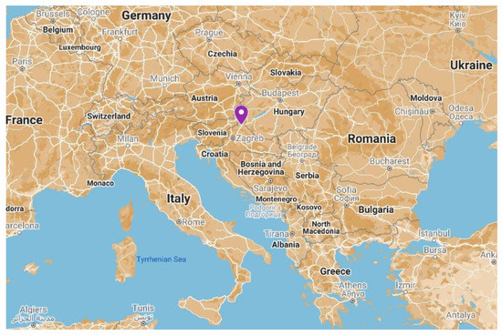
Figure 1.
Location of the production hall.
The described geological structure is very favorable for the construction of GWHP systems. In order to determine the exact geological conditions of the location, investigation work was performed, comprising test drilling and laboratory tests. The test drilling helped define the geological profile (Figure 2). The geological profile, combined with laboratory analyses, showed that the geological formations with higher water permeability reach a depth of 14 m and correspond to well-graded gravel (GW). This interval also includes thinner interlayers of silty gravel (GM). Since their influence on well efficiency is assumed to be negligible, they are not considered in further deliberation.
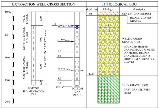
Figure 2.
Geological profile along with the extraction well’s cross-section.
Based on ground granulometry, hydraulic conductivity was estimated at k = 102 m/dan; its actual value is yet to be determined by means of a pump test. Depths exceeding 14 m included gravel with silt and clay (GM) in various ratios. Based on all the listed facts, it was concluded that ground conditions were favorable for well construction, while the geometry and other characteristics were to be adjusted to the required pump capacity, defined by the heat pump designer.
3. In-Situ Measurements of Aquifer Characteristics
The important aquifer parameters used in well design are the coefficient of hydraulic conductivity, the coefficient of transmissibility, and the storage coefficient.
Soil or rock permeability is defined by the coefficient of hydraulic conductivity, which depends on multiple factors such as: the soil’s granulometric composition, particle shape and texture, mineral composition, the coefficient of pores, level of saturation, the nature of fluids, temperature, etc. [9]. Its value is also a function of the size and shape of pores, pore connectivity efficacy, and the physical characteristics of fluids [10]. The hydrogeological parameter that also describes the aquifer is the coefficient of transmissivity (T), defined as the rate at which water can pass through the full aquifer thickness. Simply stated, it is the hydraulic conductivity multiplied by the saturated aquifer thickness [11]. Its value equals the mathematical product of hydraulic conductivity and aquifer thickness (Equation (1)).
where k is the hydraulic conductivity coefficient and m is the thickness of the aquifer.
The storage coefficient (S) or storativity is the volume of water released from storage with respect to the change in head (water level) and the surface area of the aquifer. Common values for unconfined aquifers are within the 0.05–0.3 interval [12]. It pertains to the total thickness of the saturated part of the aquifer, and its value is the mathematical product of the specific value (Ss) and aquifer thickness (m) [10].
By applying the abovementioned parameters, we defined the distance between the wells, as well as their capacities, with the final goal of ensuring the design efficiency of the heat pump. A reliable way of determining aquifer parameters is a pumping test [13], which had two specific goals in this case:
- Determining aquifer parameters;
- Measuring groundwater lowering as a consequence of pumping, in order to estimate the settlement of the surrounding terrain.
Water level lowering was monitored in both wells during the pumping test, as well as measurements of pumping capacity. The results of the pumping test helped define the aquifer parameters that are relevant for well design. The ground plan of the pumping test wells’ arrangement is shown in Figure 3, and a schematic showing the wells in relation to the heat pump is shown in Figure 4.
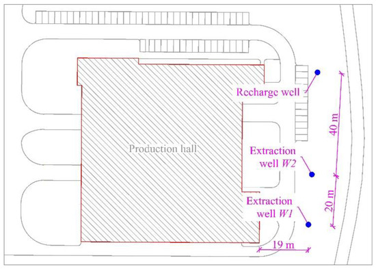
Figure 3.
Site layout.
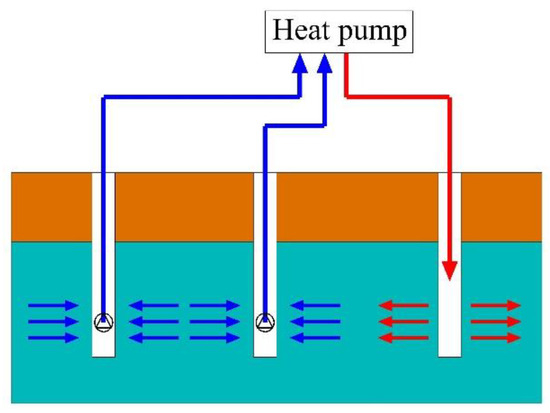
Figure 4.
Schematic view of the heat pump, two extraction wells, and the recharge well.
The total length between the extraction wells. W1 and W2. was 20.0 m. Before the pumping test, the groundwater level was measured at 3.4 m depth. This was carried out in stages with three different capacities, continually for 10 h. Figure 4 shows the pumping test results. The maximum water level lowering was measured in pumping well W1 at the capacity of q = 24 L/s, and it amounted to 40 cm. Well W2 showed a lowering of 30 cm at the same pumping capacity. The pumped quantities indicated the favorable aquifer hydrogeological characteristics and quality well construction. During the pumping test, the lowering in the exploitation well showed minimal fluctuation in dynamic water levels, which, in turn, helped in quickly reaching a balanced state between the pumped quantity and the inflow from the aquifer [14].
Based on the pumping test results (Figure 5), and using the Aquifer Test Waterloo Hydrogeologic software, the aquifer hydrogeological parameters were determined. The parameters were determined for two types of pumping test: the constant test and the step test; the results are shown in Table 1.
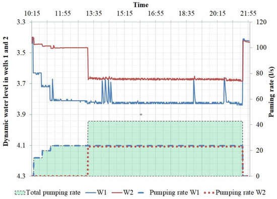
Figure 5.
Pump test results.

Table 1.
Hydrogeological parameters of the aquifer.
The resulting value of the hydraulic conductivity coefficient matches the values calculated from the granulometric curve (120 m/day), as well as the typical values for this sort of material. High values of hydraulic conductivity and transmissivity ensure highly favorable conditions for pumping groundwater in the construction of GWHP systems.
Figure 6 shows the influence of pumping in wells W1 and W2 on groundwater levels. The analyses were performed on using the pumping test results in “Drawdown” software. The software solves the Theis equation [15] and provides a graph of the lowering as a function of distance or pumping time. The presented data refer to groundwater lowering caused by the maximum pumped quantity in both pumps combined, which was q = 43 L/s in the period of 10 h. The largest groundwater lowering at the construction footing was . The groundwater lowering caused additional stress in the foundation soil as a consequence of the change in effective stress. The additional stress in this specific case was . Considering the fact that the additional stress caused by construction weight and other external factors was considerably greater, the abovementioned influence can be disregarded. Taking the geotechnical soil characteristics into account, we can conclude that water pumping in the described conditions caused negligible settlement of the production hall’s foundation.
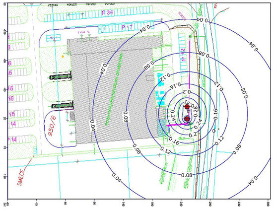
Figure 6.
The influence of pumping on settlement of the surrounding terrain.
4. Thermal Breakthrough
Water that returns into the ground through the recharge well disturbs the existing condition of the temperature field and establishes a new, unsteady temperature field; i.e., it causes the occurrence of temperature imbalance [16]. When the extraction well is influenced by the temperature imbalance, a change occurs in the temperature of the pumped water—this is called thermal breakthrough [17].
In the present case, a regular inspection of the heat pump system indicated flaws that significantly influenced its functionality. Besides technical flaws regarding system management, a problem was detected in extraction well W1. The temperature of the pumped water in wells W1 and W2 before heat pump operation was . The temperature of water returning into the ground from the heat pump was 15–16 °C, which led to a water temperature increase in well W1. In order to quantify the effect of the heat from the recharge well on water temperatures in W1 and W2, a pump test was conducted with continual water temperature monitoring. The results of the pump test are shown in Figure 7. The total duration of the pump test was around 12 h. The picture clearly indicates the effect of the recharge well water temperature on the water temperature in well W2. The water temperature in W2 showed a constant increase from the start of pumping, and after 10 h, the temperature became equal to the water temperature in the recharge well, which was . During the pump test, the water temperature in W1 remained constant; i.e., no thermal breakthrough was detected.
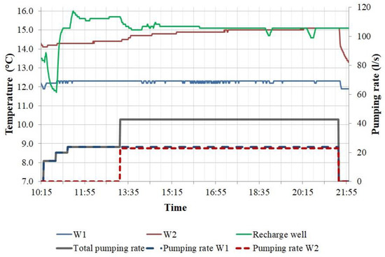
Figure 7.
Pump test results—the influence of the recharge well on the water temperature in extraction well W2.
All of the above facts led to a decrease in the efficiency of the heat pump, which caused an inability to cool the production hall to the temperature and humidity values intended by design. The cooling capacity of the system, i.e., the installed cooling power, was decreased to 40–50% of the original design values.
The thermal breakthrough was a consequence of insufficient distance between well W2 and the recharge well for the given pump quantities and the aquifer’s hydrogeological parameters. In the present case, the distance between wells was conditioned by the building’s size and the arrangement of other objects built for the hall’s function. Well W2 was constructed 40 m from the recharge well, and W1 at 60 m. The thermal breakthrough can be resolved by constructing additional recharge wells at adequate distances, in order to reduce the load on the existing recharge well.
5. Conclusions
A groundwater heat pump is an energy-efficient and environmentally friendly building-heating and air-conditioning system. Some of the major prerequisites affecting the functionality of such a system are the hydrogeological parameters of the aquifer. By analyzing their values, an estimate can be given on the feasibility and the efficiency of the GWHP system for a specific case.
The northwest part of Croatia is rich in groundwater; along with favorable hydrogeological conditions; these facts indicate the large potential for GWHP system construction on a larger scale. Design based on quality data can ensure the optimal exploitation of groundwater’s potential, as well as the prevention of possible unwanted side effects during exploitation. Investigative work, including pump tests and drilling, can determine the aquifer’s hydrogeological characteristics, as well as the parameters required for the analysis of the effects of groundwater pumping on terrain settlement. During investigation work, it is important to identify any changes in the geological structure of the soil, and special attention needs to be given to determining grain size and permeability. Design solutions—and, consequently, the final system’s efficiency—depend on the scope of investigation work. In order to prevent thermal breakthrough, recharge wells need to be planned at an adequate distance downstream from the extraction wells, taking into account the hydraulic gradient, hydraulic conductivity, and other relevant parameters.
Author Contributions
S.S. was in charge of geotechnical investigation work and the pump test. F.D. prepared the draft of the paper and contributed to the analyses and conclusion. K.G. and S.S. performed the aquifer parameter analyses. B.M.-K. commented on the results and provided the theoretical background of the problem. All authors have read and agreed to the published version of the manuscript.
Institutional Review Board Statement
Not applicable.
Informed Consent Statement
Not applicable.
Data Availability Statement
The data presented in this study are available on request from the corresponding author.
Conflicts of Interest
The authors declare no conflict of interest.
References
- Garman, D.K. Geothermal Technologies Program: Buried Treasure—The Environmental, Economic, and Employment Benefits of Geothermal Energy; U.S. Department of Energy: Washington, DC, USA, 2004.
- Younis, M.; Bolisetti, T.; Ting, D.S.K. Ground source heat pump systems: Current status. Int. J. Environ. Stud. 2010, 67, 405–415. [Google Scholar] [CrossRef]
- Bundschuh, J.; Chen, G. Sustainable Energy Solutions i in Agriculture; Taylor & Francis Group: London, UK, 2014. [Google Scholar]
- Sommer, W.; Valstar, J.; Leusbrock, I.; Grotenhuis, T.; Rijnaarts, H. Optimization and spatial pattern of large-scale aquifer thermal energy storage. Appl. Energy 2015, 137, 322–337. [Google Scholar] [CrossRef]
- Ooka, R.; Nam, Y.; Shiba, Y.; Tanifuji, K.; Okumura, T.; Miwa, Y. Development of groundwater circulation heat pump system. HVAC R Res. 2011, 17, 556–565. [Google Scholar]
- Schout, G.; Drijver, B.; Gutierrez-Neri, M.; Schotting, R. Analysis of recovery efficiency in high-temperature aquifer thermal energy storage: A Rayleigh-based method. Hydrogeol. J. 2014, 22, 281–291. [Google Scholar] [CrossRef]
- Ganguly, S.; Kumar, M.S.M.; Date, A.; Akbarzadeh, A. Numerical investigation of temperature distribution and thermal performance while charging-discharging thermal energy in aquifer. Appl. Therm. Eng. 2017, 115, 756–773. [Google Scholar] [CrossRef]
- Røksland, M.; Basmoen, T.A.; Sui, D. Geothermal Energy Extraction from Abandoned Wells. Energy Procedia 2017, 105, 244–249. [Google Scholar] [CrossRef]
- Bačani, A.; Vlahović, T. Hidrogeologija Primjena u graditeljstvu, 1st ed.; Sveučilište u Splitu, Fakultet Građevinarstva, Arhitekture i geodezije: Split, Croatia, 2012. [Google Scholar]
- Miletić, P.; Heinrich-Miletić, M. Uvod u Kvantitativnu Hidrogeologiju: Stijene Međuzrnske Poroznosti; Rudarsko-Geološko-Naftni fakultet: Zagreb, Croatia, 1981. [Google Scholar]
- Kelly, C.; Wiliams, H.; Misstear, B.M.; Motherway, K. Aquifer Properties—A reference manual and guide. Geol. Surv. Irel. Environ. Prot. Agency 2015, 14–17. [Google Scholar]
- Ferris, J.G.; Knowles, D.B.; Brown, R.H.; Stallman, R.W. Theory of Aquifer Tests; U.S. Government Publishing Office: Washington, DC, USA, 1962.
- Singh, S.K. Identification of aquifer parameters from residual drawdowns: An optimization approach. Hydrol. Sci. J. 2006, 51, 1139–1148. [Google Scholar] [CrossRef]
- Pollak, Z. Hidrogeologija za Građevinare, 1st ed.; Građevinski fakultet Sveučilišta u Zagrebu: Zagreb, Croatia, 1995. [Google Scholar]
- Theis, C.V. The relation between the lowering of the Piezometric surface and the rate and duration of discharge of a well using ground-water storage. Ind. Fabr. Prod. Rev. 1935, 16, 519–524. [Google Scholar] [CrossRef]
- Russo, L.S.; Gnavi, L.; Roccia, E.; Taddia, G.; Verda, V. Groundwater Heat Pump (GWHP) system modeling and Thermal Affected Zone (TAZ) prediction reliability: Influence of temporal variations in flow discharge and injection temperature. Geothermics 2014, 51, 103–112. [Google Scholar] [CrossRef]
- Jiang, Y.; Wang, X.; Li, M.; Gao, Q. Investigations on heat flow characteristics of the aquifer for groundwater heat pump (GWHP) composed of different well types. Int. J. Green Energy 2019, 16, 857–866. [Google Scholar] [CrossRef]
Publisher’s Note: MDPI stays neutral with regard to jurisdictional claims in published maps and institutional affiliations. |
© 2020 by the authors. Licensee MDPI, Basel, Switzerland. This article is an open access article distributed under the terms and conditions of the Creative Commons Attribution (CC BY) license (https://creativecommons.org/licenses/by/4.0/).