
Features of Degassing from Overburden Rock Massifs: A Case Study Using Radon

 ,
,  ,
,  ,
,
Abstract
:1. Introduction
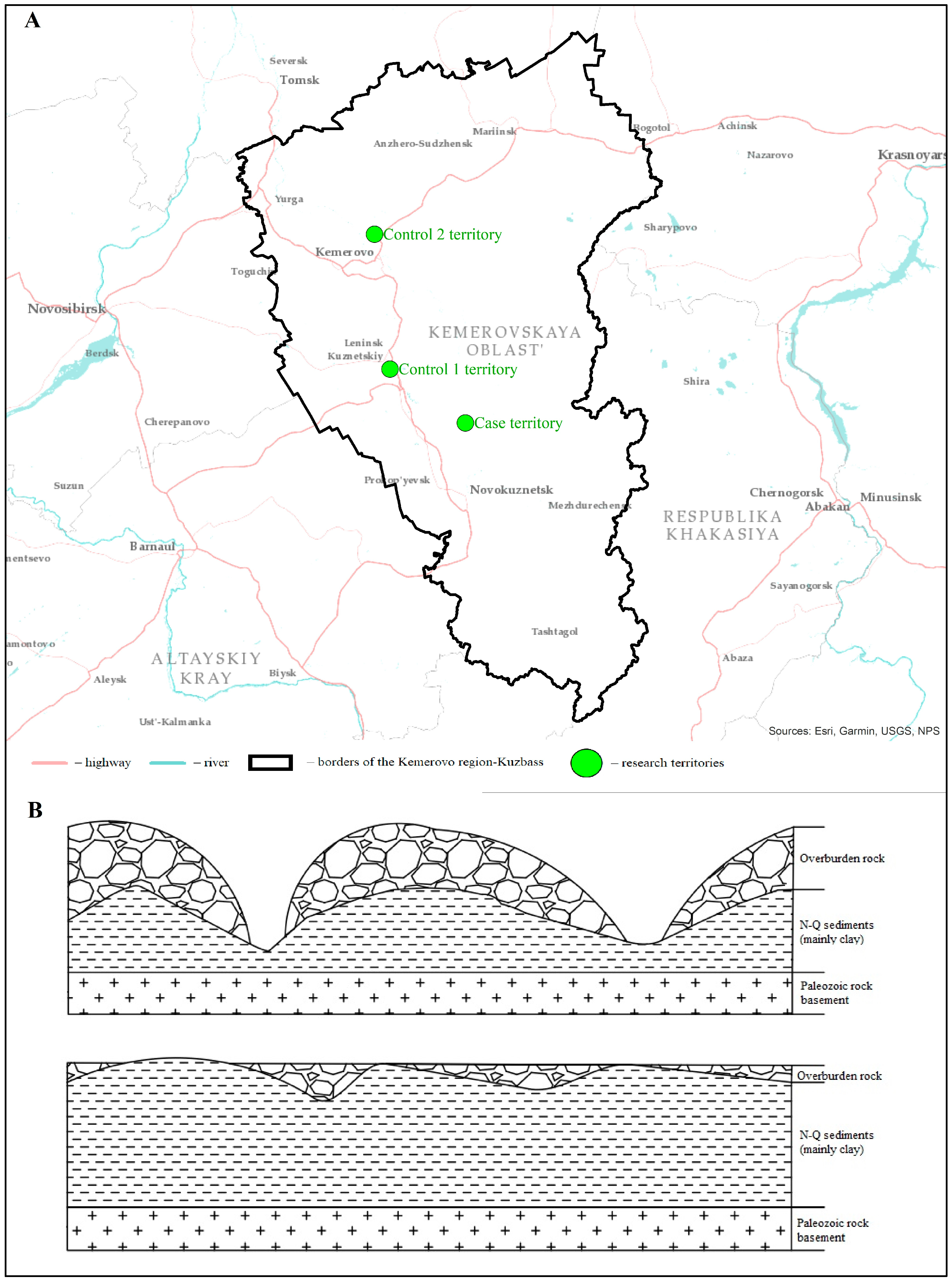
2. Materials and Methods
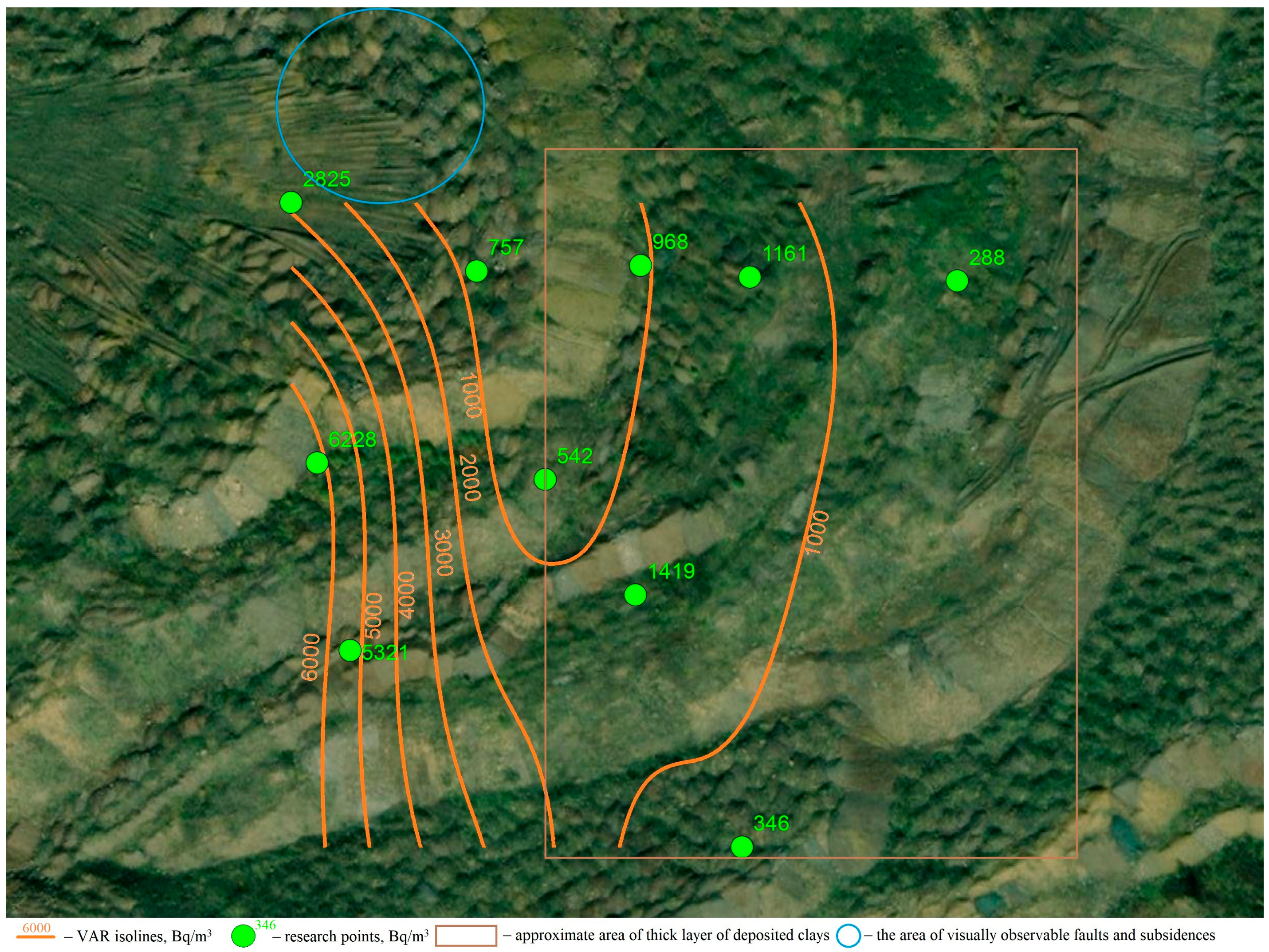
2.1. VAR and RFD Measurement
- V1 is the sample volume in sample chamber, l, V1 = 0.046 l;
- t is the time elapsed from the end of air sampling (t1) to the start of measurements (t2), min; t = t2 − t1;
- Q is the measured VAR by measurement unit, Bq/m3.
- λ is the radon decay constant, 1/s;
- texp is the duration of coal sampling in chamber NK-32, s;
- S is the working surface area NK-32, m2;
- f is the correction factor taking into account the influence of NK-32 on the test object, rel. units.
2.2. Statistical Analysis and Spatial Methods
3. Results
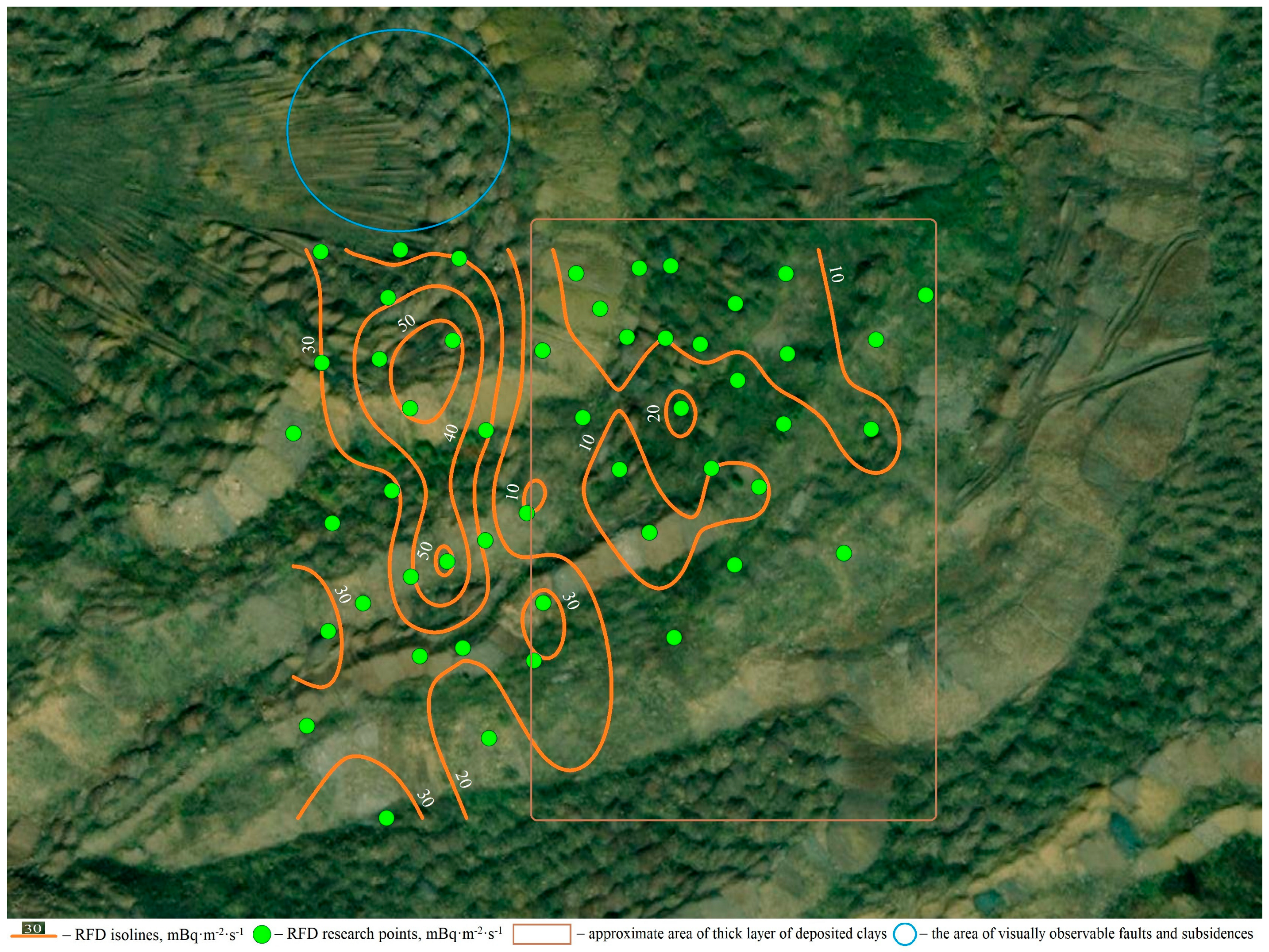
3.1. RFD
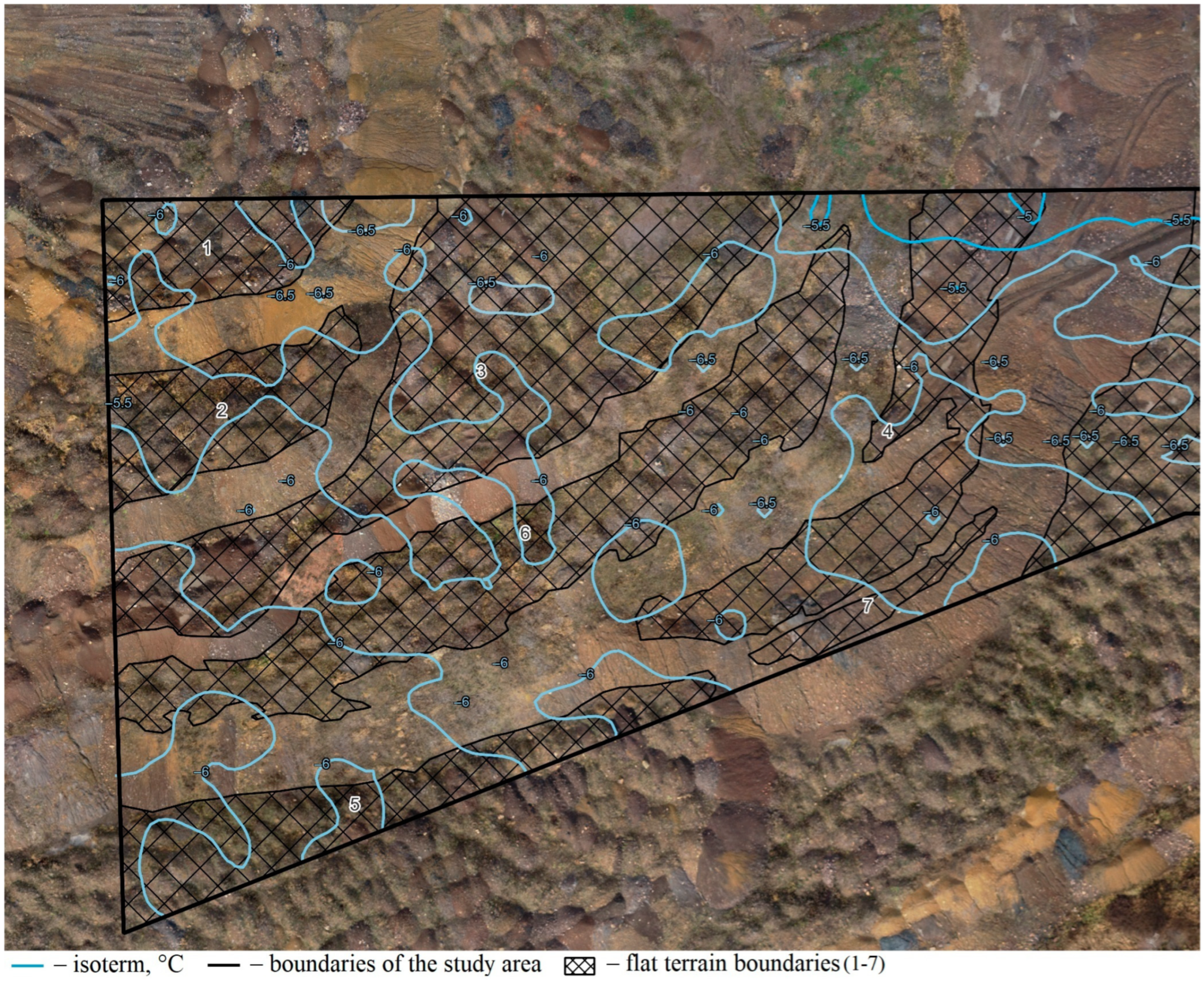
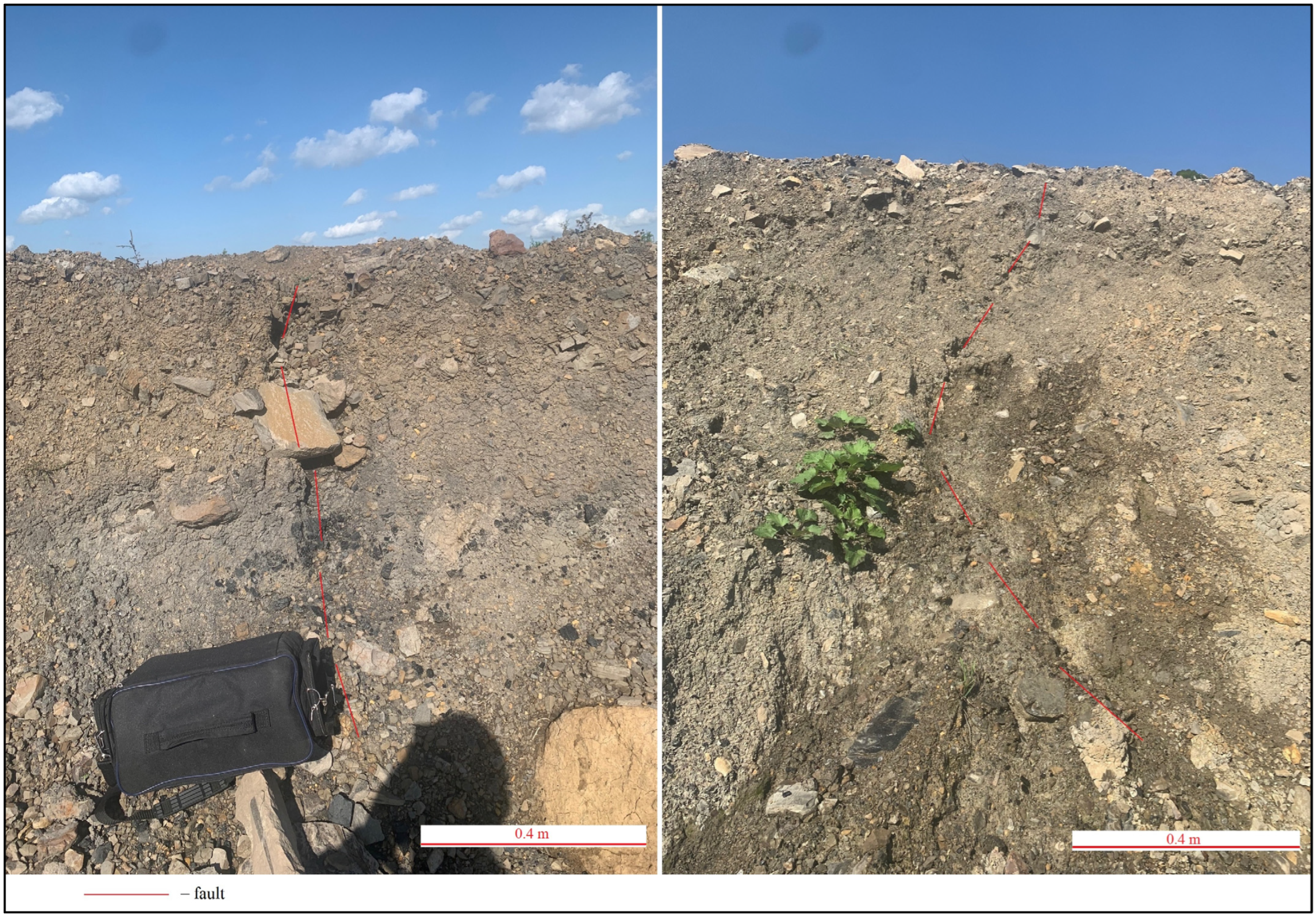
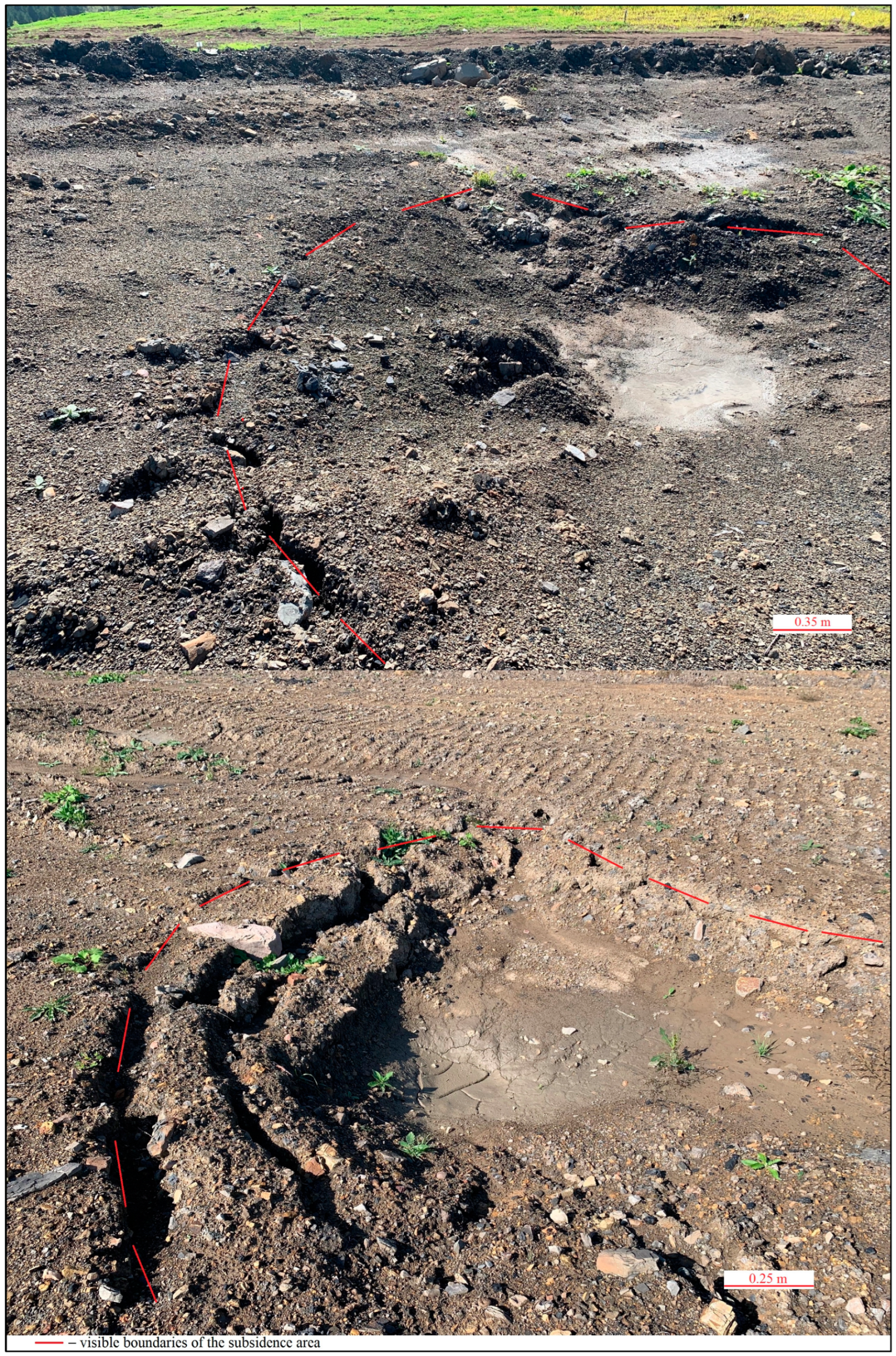
3.2. Visual Inspection of the Study Area for the Presence of Fractures
4. Discussion
5. Conclusions
Author Contributions
Funding
Data Availability Statement
Conflicts of Interest
References
- Bazaluk, O.; Anisimov, O.; Saik, P.; Lozynskyi, V.; Akimov, O.; Hrytsenko, L. Determining the Safe Distance for Mining Equipment Operation When Forming an Internal Dump in a Deep Open Pit. Sustainability 2023, 15, 5912. [Google Scholar] [CrossRef]
- Prokopenko, S.A.; Ludzish, V.S.; Lesin, Y.V.; Tyulenev, M.A.; Sushko, A.V. Structural Peculiarities of Coal Mine Waste Piles in Kuzbass. J. Min. Sci. 2017, 53, 92–98. [Google Scholar] [CrossRef]
- Makridin, E.V.; Tyulenev, M.A.; Markov, S.O.; Lesin, Y.V.; Murko, E.V. Overburden management towards higher safety in coal mining regions. Min. Informational Anal. Bull. 2020, 12, 89–102. [Google Scholar] [CrossRef]
- Cheskidov, V.I.; Bobylsky, A.S. Technology and Ecology of Dumping at Open Pit Mines in Kuzbass. J. Min. Sci. 2017, 53, 882–889. [Google Scholar] [CrossRef]
- Makridin, E.V.; Tyulenev, M.A.; Markov, S.O. Experimental study of the quarry wastewater filtering in coarse-grained massifs of rock debris at kamyshansky open pit mine. Teh. Tehnol. Gorn. Dela 2020, 2, 4–25. [Google Scholar] [CrossRef]
- Tyulenev, M.A.; Markov, S.O.; Gasanov, M.A.; Zhironkin, S.A. Numerical Modeling in the Structural Study of Technogenic Rock Array. Geotech. Geol. Eng. 2018, 36, 2789–2797. [Google Scholar] [CrossRef]
- Ivanova, S.; Vesnina, A.; Fotina, N.; Prosekov, A. An Overview of Carbon Footprint of Coal Mining to Curtail Greenhouse Gas Emissions. Sustainability 2022, 14, 15135. [Google Scholar] [CrossRef]
- Amrani, M.; Taha, Y.; El Haloui, Y.; Benzaazoua, M.; Hakkou, R. Sustainable Reuse of Coal Mine Waste: Experimental and Economic Assessments for Embankments and Pavement Layer Applications in Morocco. Minerals 2020, 10, 851. [Google Scholar] [CrossRef]
- Amrani, M.; Taha, Y.; Kchikach, A.; Benzaazoua, M.; Hakkou, R. Field and Economic Studies on Mine Waste: Sustainable Reuse as Aggregates for Low Traffic Pavement Structure. Sustainability 2022, 14, 12540. [Google Scholar] [CrossRef]
- do Amaral Filho, J.R.; Gcayiya, M.; Kotsiopoulos, A.; Broadhurst, J.L.; Power, D.; Harrison, S.T.L. Valorization of South African Coal Wastes through Dense Medium Separation. Minerals 2022, 12, 1519. [Google Scholar] [CrossRef]
- Khalil, A.; Taha, Y.; Benzaazoua, M.; Hakkou, R. Applied Methodological Approach for the Assessment of Soil Contamination by Trace Elements around Abandoned Coal Mines—A Case Study of the Jerada Coal Mine, Morocco. Minerals 2023, 13, 181. [Google Scholar] [CrossRef]
- Mishra, A.; Das, S.K.; Reddy, K.R. Processing Coalmine Overburden Waste Rock as Replacement to Natural Sand: Environmental Sustainability Assessment. Sustainability 2022, 14, 14853. [Google Scholar] [CrossRef]
- Luo, H.; Zhou, W.; Jiskani, I.M.; Wang, Z. Analyzing Characteristics of Particulate Matter Pollution in Open-Pit Coal Mines: Implications for Green Mining. Energies 2021, 14, 2680. [Google Scholar] [CrossRef]
- Wang, Z.; Zhou, W.; Jiskani, I.M.; Luo, H.; Ao, Z.; Mvula, E.M. Annual Dust Pollution Characteristics and Its Prevention and Control for Environmental Protection in Surface Mines. Sci. Total Environ. 2022, 825, 153949. [Google Scholar] [CrossRef]
- Leshukov, T.; Legoshchin, K.; Yakovenko, O.; Bach, S.; Russakov, D.; Dimakova, D.; Vdovina, E.; Baranova, E.; Avdeev, K.; Kolpina, E.; et al. Fractional Composition and Toxicity Coal–Rock of PM10-PM0.1 Dust near an Opencast Coal Mining Area and Coal-Fired Power Station. Sustainability 2022, 14, 16594. [Google Scholar] [CrossRef]
- Park, I.; Tabelin, C.B.; Jeon, S.; Li, X.; Seno, K.; Ito, M.; Hiroyoshi, N. A Review of Recent Strategies for Acid Mine Drainage Prevention and Mine Tailings Recycling. Chemosphere 2019, 219, 588–606. [Google Scholar] [CrossRef]
- Marove, C.A.; Sotozono, R.; Tangviroon, P.; Tabelin, C.B.; Igarashi, T. Assessment of Soil, Sediment and Water Contaminations around Open-Pit Coal Mines in Moatize, Tete Province, Mozambique. Environ. Adv. 2022, 8, 100215. [Google Scholar] [CrossRef]
- Pondja, E.A.; Persson, K.M.; Matsinhe, N.P. Assessment of Coal Mine Water in Moatize by Static and Leaching Tests. Sustain. Water Resour. Manag. 2017, 3, 403–412. [Google Scholar] [CrossRef]
- Marove, C.A.; Tangviroon, P.; Tabelin, C.B.; Igarashi, T. Leaching of Hazardous Elements from Mozambican Coal and Coal Ash. J. Afr. Earth Sci. 2020, 168, 103861. [Google Scholar] [CrossRef]
- Silva, N.C.; Chagas, E.G.L.; Abreu, C.B.; Dias, D.C.S.; Lopez, D.; Guerreiro, E.T.Z.; Alberti, H.L.C.; Braz, M.L.; Branco, O.; Fleming, P. Radon as a Natural Tracer for Gas Transport within Uranium Waste Rock Piles. Radiat. Prot. Dosim. 2014, 160, 74–77. [Google Scholar] [CrossRef]
- Fabiańska, M.J.; Ciesielczuk, J.; Kruszewski, Ł.; Misz-Kennan, M.; Blake, D.R.; Stracher, G.; Moszumańska, I. Gaseous Compounds and Efflorescences Generated in Self-Heating Coal-Waste Dumps—A Case Study from the Upper and Lower Silesian Coal Basins (Poland). Int. J. Coal Geol. 2013, 116–117, 247–261. [Google Scholar] [CrossRef]
- Hu, X.; Sun, Q.; Shi, Q.; Wang, N.; Geng, J.; Xue, S. Radon Exhalation Characteristics after Pyrolysis of Long Flame Coal. Sci. Total Environ. 2023, 904, 167228. [Google Scholar] [CrossRef]
- Ribeiro, J.; Suárez-Ruiz, I.; Flores, D. Coal Related Fires in Portugal: New Occurrences and New Insights on the Characterization of Thermally Affected and Non-Affected Coal Waste Piles. Int. J. Coal Geol. 2022, 252, 103941. [Google Scholar] [CrossRef]
- Carras, J.N.; Day, S.J.; Saghafi, A.; Williams, D.J. Greenhouse Gas Emissions from Low-Temperature Oxidation and Spontaneous Combustion at Open-Cut Coal Mines in Australia. Int. J. Coal Geol. 2009, 78, 161–168. [Google Scholar] [CrossRef]
- Nádudvari, Á.; Cabała, J.; Marynowski, L.; Jabłońska, M.; Dziurowicz, M.; Malczewski, D.; Kozielska, B.; Siupka, P.; Piotrowska-Seget, Z.; Simoneit, B.R.T.; et al. High Concentrations of HgS, MeHg and Toxic Gas Emissions in Thermally Affected Waste Dumps from Hard Coal Mining in Poland. J. Hazard. Mater. 2022, 431, 128542. [Google Scholar] [CrossRef]
- Liang, Y.; Liang, H.; Zhu, S. Mercury Emission from Spontaneously Ignited Coal Gangue Hill in Wuda Coalfield, Inner Mongolia, China. Fuel 2016, 182, 525–530. [Google Scholar] [CrossRef]
- Etiope, G.; Lombardi, S. Evidence for Radon Transport by Carrier Gas through Faulted Clays in Italy. J. Radioanal. Nucl. Chem. Artic. 1995, 193, 291–300. [Google Scholar] [CrossRef]
- Cvetković, M.; Kapuralić, J.; Pejić, M.; Kolenković Močilac, I.; Rukavina, D.; Smirčić, D.; Kamenski, A.; Matoš, B.; Špelić, M. Soil Gas Measurements of Radon, CO2 and Hydrocarbon Concentrations as Indicators of Subsurface Hydrocarbon Accumulation and Hydrocarbon Seepage. Sustainability 2021, 13, 3840. [Google Scholar] [CrossRef]
- Dyck, W.; Jonasson, I.R. Chapter 11 Radon. In Handbook of Exploration Geochemistry; Hale, M., Ed.; Geochemical Remote Sensing of the Sub-Surface; Elsevier Science B.V.: Amsterdam, The Netherlands, 2000; Volume 7, pp. 353–394. [Google Scholar]
- Wang, S.; Luo, K.; Wang, X.; Sun, Y. Estimate of Sulfur, Arsenic, Mercury, Fluorine Emissions Due to Spontaneous Combustion of Coal Gangue: An Important Part of Chinese Emission Inventories. Environ. Pollut. 2016, 209, 107–113. [Google Scholar] [CrossRef]
- Tan, B.; Zhang, F.; Zhang, Q.; Wei, H.; Shao, Z. Firefighting of Subsurface Coal Fires with Comprehensive Techniques for Detection and Control: A Case Study of the Fukang Coal Fire in the Xinjiang Region of China. Environ. Sci. Pollut. Res. 2019, 26, 29570–29584. [Google Scholar] [CrossRef]
- Liu, Y.G.; Yu, L.N.; Wang, H.C. Study on Countermeasures of Coal Gangue Pollution Prevention and Regional Sustainable Development in China. Appl. Mech. Mater. 2013, 307, 510–513. [Google Scholar] [CrossRef]
- Shao, Z.; Wang, D.; Cao, K.; Si, W.; Li, Y.; Liu, J. Treatment of Smouldering Coal Refuse Piles: An Application in China. Environ. Technol. 2020, 41, 3105–3118. [Google Scholar] [CrossRef]
- Zhao, P.; Zhuo, R.; Li, S.; Lin, H.; Shu, C.-M.; Shuang, H.; Wei, Z. Greenhouse Gas Protection and Control Based upon the Evolution of Overburden Fractures under Coal Mining: A Review of Methods, Influencing Factors, and Techniques. Energy 2023, 284, 129158. [Google Scholar] [CrossRef]
- World Health Organization. WHO Handbook on Indoor Radon: A Public Health Perspective; World Health Organization: Geneva, Switzerland, 2009; ISBN 978-92-4-154767-3. [Google Scholar]
- Hong, Y.; Du, H.; Chen, M. Bearing Capacity Analysis of the Weak Basement, Progressive Destruction Analysis, and Evaluation of the Dump on an Inclined Strip Section Using the Upper-Limit Method: A Case Study in an Anonymous Open-Cast Coal Mine. Sustainability 2023, 15, 10240. [Google Scholar] [CrossRef]
- Ren, H.; Zhao, Y.; Xiao, W.; Yang, X.; Ding, B.; Chen, C. Monitoring Potential Spontaneous Combustion in a Coal Waste Dump after Reclamation through Unmanned Aerial Vehicle RGB Imagery Based on Alfalfa Aboveground Biomass. Land Degrad. Dev. 2022, 33, 2728–2742. [Google Scholar] [CrossRef]
- Ren, H.; Xiao, W.; Zhao, Y. Examining the Effect of Spontaneous Combustion on Vegetation Restoration at Coal Waste Dumps after Reclamation: Taking Medicago sativa L. (Alfalfa) as an Indicator. Sci. Total Environ. 2023, 901, 165668. [Google Scholar] [CrossRef]
- Abramowicz, A.; Rahmonov, O.; Chybiorz, R.; Ciesielczuk, J. Vegetation as an Indicator of Underground Smoldering Fire on Coal-Waste Dumps. Fire Saf. J. 2021, 121, 103287. [Google Scholar] [CrossRef]
- Ren, H.; Zhao, Y.; Xiao, W.; Zhang, J.; Chen, C.; Ding, B.; Yang, X. Vegetation Growth Status as an Early Warning Indicator for the Spontaneous Combustion Disaster of Coal Waste Dump after Reclamation: An Unmanned Aerial Vehicle Remote Sensing Approach. J. Environ. Manag. 2022, 317, 115502. [Google Scholar] [CrossRef]
- Osintseva, M. Assessment of Soil Properties in Technogenically Disturbed Lands of Kemerovo Oblast—Kuzbass. Qubahan Acad. J. 2023, 3, 77–92. [Google Scholar] [CrossRef]
- Podurets, O.I. Spatial variability of the content of heavy metals in the soil cover under the influence of a coal mining enterprise. Ugol’ 2023, 10, 51–58. [Google Scholar] [CrossRef]
- Shao, Z.; Deng, R.; Zhang, G.; Li, Y.; Tang, X.; Zhang, W. 3D Thermal Mapping of Smoldering Coal Gangue Pile Fires Using Airborne Thermal Infrared Data. Case Stud. Therm. Eng. 2023, 48, 103146. [Google Scholar] [CrossRef]
- Zubíček, V.; Hudeček, V.; Orlíková, L.; Dandoš, R.; Jadviščok, P.; Adjiski, V.; Dlouhá, D. Thermal Signatures of Relict Coal Spoil, Waste and Tailing Dumps. Int. J. Min. Reclam. Environ. 2023, 1–13. [Google Scholar] [CrossRef]
- Portola, V.A.; Tailakov, O.V.; Lee, H.U.; Sobolev, V.V.; Bobrovnikova, A.A. Detection, location and assessment of underground fires using radon anomalies on the day surface. Ugol’ 2021, 47–52. [Google Scholar] [CrossRef]
- Tovele, G.S.V.; Han, L.; Shu, J.S. Variation of Open-Pit Waste Dump Specimens Under Effective Pressure Influence. Front. Earth Sci. 2021, 8, 582918. [Google Scholar] [CrossRef]
- Upadhyay, O.P.; Sharma, D.K.; Singh, D.P. Factors Affecting Stability of Waste Dumps in Mines. Int. J. Surf. Min. Reclam. Environ. 1990, 4, 95–99. [Google Scholar] [CrossRef]
- Deng, H.; Zhao, B.; Xiao, Y.; Tian, G. Experimental Study on Macroscopic Mechanical Characteristics and Microscopic Pore Structure Evolution of Soil–Rock Mixture under Repeated Freeze–Thaw Cycles. Appl. Sci. 2023, 13, 11504. [Google Scholar] [CrossRef]
- Zaalishvili, V.; Melkov, D.; Revazov, M. Relationship of radon emanation with the level of external impact according to large landslides monitoring in mountain areas. Sustain. Dev. Mt. Territ. 2021, 13, 564–575. [Google Scholar] [CrossRef]
- Li, Y.; Lv, G.; Wang, D.; Su, W.; Wei, Z. Erosion Failure of Slope in a Dump with Ground Fissure under Heavy Rain. Water 2022, 14, 3425. [Google Scholar] [CrossRef]
- Misz-Kennan, M.; Tabor, A. Chapter 15—The Thermal History of Select Coal-Waste Dumps in the Upper Silesian Coal Basin, Poland. In Coal and Peat Fires: A Global Perspective; Stracher, G.B., Prakash, A., Sokol, E.V., Eds.; Elsevier: Boston, MA, USA, 2015; pp. 431–462. ISBN 978-0-444-59509-6. [Google Scholar]
- Musina, V.R.; Golovko, I.V.; Shermatova, S. Type of Crossing of Coal Waste Dumps by Geodynamical Dangerous Zones. MIAB. Min. Inf. Anal. Bull. 2020, 233–241. [Google Scholar] [CrossRef]
- Kumar, A.; Das, S.K.; Nainegali, L.; Reddy, K.R. Phytostabilization of Coalmine Overburden Waste Rock Dump Slopes: Current Status, Challenges, and Perspectives. Bull. Eng. Geol. Environ. 2023, 82, 130. [Google Scholar] [CrossRef]
- Radosz, Ł.; Chmura, D.; Prostański, D.; Woźniak, G. The Soil Respiration of Coal Mine Heaps’ Novel Ecosystems in Relation to Biomass and Biotic Parameters. Energies 2023, 16, 7083. [Google Scholar] [CrossRef]


| No. | Control 1 Territory | Case Territory | ||
|---|---|---|---|---|
| Soil Radon VAR, Bq/m3 | SE, Bq/m3 | Soil Radon VAR, Bq/m3 | SE, Bq/m3 | |
| 1 | 5928.4 | 1777.7 | 288.0 | 86.4 |
| 2 | 7934.4 | 2379.6 | 1161.0 | 348.0 |
| 3 | 2898.1 | 869.4 | 968.0 | 290.3 |
| 4 | 4341.4 | 1301.8 | 757.0 | 227.0 |
| 5 | 5996.4 | 1798.1 | 542.0 | 162.5 |
| 6 | 9691.8 | 2907.1 | 1419.0 | 425.0 |
| 7 | 10,035.5 | 3010.0 | 346.0 | 103.8 |
| 8 | 9812.0 | 2942.9 | 2825.0 | 847.2 |
| 9 | 4879.7 | 1463.3 | 6228.4 | 1867.9 |
| 10 | - | - | 5321.0 | 1595.8 |
| Research Area | Radon Statistics, mBq·m−2·s−1 | |||||
|---|---|---|---|---|---|---|
| RFD | SE | Mediana | Max | Min | Interval | |
| Control 1 | 58.97 | 2.33 | 57 | 160 | 12 | 148 |
| Control 2 | 18.36 | 2.56 | 12 | 77 | 2 | 75 |
| Case | 21 | 1.93 | 18.5 | 53 | 3 | 50 |
| All | 42.78 | 1.98 | 38 | 160 | 2 | 158 |
| Global Moran’s I | Getis-Ord General G | |
|---|---|---|
| Observed | 0.738386 | 0.005647 |
| Expected | −0.020408 | 0.004653 |
| Standard Deviation | 0.006057 | 0.000000 |
| z-score | 9.750153 | 2.338623 |
| p-value | 0.000000 | 0.019355 |
Disclaimer/Publisher’s Note: The statements, opinions and data contained in all publications are solely those of the individual author(s) and contributor(s) and not of MDPI and/or the editor(s). MDPI and/or the editor(s) disclaim responsibility for any injury to people or property resulting from any ideas, methods, instructions or products referred to in the content. |
© 2023 by the authors. Licensee MDPI, Basel, Switzerland. This article is an open access article distributed under the terms and conditions of the Creative Commons Attribution (CC BY) license (https://creativecommons.org/licenses/by/4.0/).
Share and Cite
Leshukov, T.; Larionov, A.; Nastavko, E.; Kaizer, P.; Legoshchin, K. Features of Degassing from Overburden Rock Massifs: A Case Study Using Radon. Earth 2024, 5, 1-19. https://doi.org/10.3390/earth5010001
Leshukov T, Larionov A, Nastavko E, Kaizer P, Legoshchin K. Features of Degassing from Overburden Rock Massifs: A Case Study Using Radon. Earth. 2024; 5(1):1-19. https://doi.org/10.3390/earth5010001
Chicago/Turabian StyleLeshukov, Timofey, Aleksey Larionov, Ekaterina Nastavko, Philipp Kaizer, and Konstantin Legoshchin. 2024. "Features of Degassing from Overburden Rock Massifs: A Case Study Using Radon" Earth 5, no. 1: 1-19. https://doi.org/10.3390/earth5010001
APA StyleLeshukov, T., Larionov, A., Nastavko, E., Kaizer, P., & Legoshchin, K. (2024). Features of Degassing from Overburden Rock Massifs: A Case Study Using Radon. Earth, 5(1), 1-19. https://doi.org/10.3390/earth5010001